powerequipment - manuals.ggp-group.commanuals.ggp-group.com/71501046_0.pdf · powerequipment honda...
TRANSCRIPT

POWER EQUIPMENT
Honda Europe Power Equipment S.A.Pôle 45 - Rue des Châtaigniers45140 ORMES - FRANCE
BRUSH CUTTERSDEBROUSSAILLEUSES
MOTORSENSEN
OWNER’S MANUALMANUEL D’UTILISATEUR
BETRIEBSANLEITUNG
D GB F
UMK425EUMK435E
* 00X3C VJ 5 F13*
Livre_D-GB-F.book Page 1 Vendredi, 10. février 2006 2:15 14
71501046/0

2
DINHALTSVERZEICHNISZUR BEACHTUNG. . . . . . . . . . . . . . . . . . . . . . . . . . . . . . . . . . . . . . . . . . . . . . . . . . . . . . . . . . . . . . 5
SICHERHEITSHINWEISE . . . . . . . . . . . . . . . . . . . . . . . . . . . . . . . . . . . . . . . . . . . . . . . . . . . . . . . 6
EINFÜHRUNG . . . . . . . . . . . . . . . . . . . . . . . . . . . . . . . . . . . . . . . . . . . . . . . . . . . . . . . . . . . . . . . . 12Erklärung der in der Vorliegenden Anleitung verwendeten Codes . . . . . . . . . . . . . . . . . . . . . . . . . 12
ALLGEMEINE BESCHREIBUNG . . . . . . . . . . . . . . . . . . . . . . . . . . . . . . . . . . . . . . . . . . . . . . . . . 14Teile des Geräts . . . . . . . . . . . . . . . . . . . . . . . . . . . . . . . . . . . . . . . . . . . . . . . . . . . . . . . . . . . . . . . 14Geräte-Kennzeichnung . . . . . . . . . . . . . . . . . . . . . . . . . . . . . . . . . . . . . . . . . . . . . . . . . . . . . . . . . . 16Sicherheitsaufkleber . . . . . . . . . . . . . . . . . . . . . . . . . . . . . . . . . . . . . . . . . . . . . . . . . . . . . . . . . . . . 16
MONTAGE . . . . . . . . . . . . . . . . . . . . . . . . . . . . . . . . . . . . . . . . . . . . . . . . . . . . . . . . . . . . . . . . . . . 18Griffe . . . . . . . . . . . . . . . . . . . . . . . . . . . . . . . . . . . . . . . . . . . . . . . . . . . . . . . . . . . . . . . . . . . . . . . . 18Integralschutz . . . . . . . . . . . . . . . . . . . . . . . . . . . . . . . . . . . . . . . . . . . . . . . . . . . . . . . . . . . . . . . . . 20Montage des Mähwerks . . . . . . . . . . . . . . . . . . . . . . . . . . . . . . . . . . . . . . . . . . . . . . . . . . . . . . . . . 20Montage und Einstellung des Tragegeschirrs. . . . . . . . . . . . . . . . . . . . . . . . . . . . . . . . . . . . . . . . . 24
VORBEREITUNG UND ÜBERPRÜFUNG VOR DEM EINSATZ . . . . . . . . . . . . . . . . . . . . . . . . . . 26Ausgleich des Geräts . . . . . . . . . . . . . . . . . . . . . . . . . . . . . . . . . . . . . . . . . . . . . . . . . . . . . . . . . . . 26Füllen des Kraftstofftanks . . . . . . . . . . . . . . . . . . . . . . . . . . . . . . . . . . . . . . . . . . . . . . . . . . . . . . . . 28Füllen des Ölbehälters . . . . . . . . . . . . . . . . . . . . . . . . . . . . . . . . . . . . . . . . . . . . . . . . . . . . . . . . . . 30Kontrolle des Ölstands . . . . . . . . . . . . . . . . . . . . . . . . . . . . . . . . . . . . . . . . . . . . . . . . . . . . . . . . . . 30Vor der Inbetriebnahme . . . . . . . . . . . . . . . . . . . . . . . . . . . . . . . . . . . . . . . . . . . . . . . . . . . . . . . . . 30
STARTEN UND ABSTELLEN DES MOTORS. . . . . . . . . . . . . . . . . . . . . . . . . . . . . . . . . . . . . . . . 32Kaltstart . . . . . . . . . . . . . . . . . . . . . . . . . . . . . . . . . . . . . . . . . . . . . . . . . . . . . . . . . . . . . . . . . . . . . . 32Warmstart . . . . . . . . . . . . . . . . . . . . . . . . . . . . . . . . . . . . . . . . . . . . . . . . . . . . . . . . . . . . . . . . . . . . 34Abstellen des Motors. . . . . . . . . . . . . . . . . . . . . . . . . . . . . . . . . . . . . . . . . . . . . . . . . . . . . . . . . . . . 34
GEBRAUCH . . . . . . . . . . . . . . . . . . . . . . . . . . . . . . . . . . . . . . . . . . . . . . . . . . . . . . . . . . . . . . . . . . 36Arbeitsposition. . . . . . . . . . . . . . . . . . . . . . . . . . . . . . . . . . . . . . . . . . . . . . . . . . . . . . . . . . . . . . . . . 36
WARTUNG . . . . . . . . . . . . . . . . . . . . . . . . . . . . . . . . . . . . . . . . . . . . . . . . . . . . . . . . . . . . . . . . . . . 48Einstellung des Vergasers . . . . . . . . . . . . . . . . . . . . . . . . . . . . . . . . . . . . . . . . . . . . . . . . . . . . . . . 48Überprüfung der Zündkerze . . . . . . . . . . . . . . . . . . . . . . . . . . . . . . . . . . . . . . . . . . . . . . . . . . . . . . 48Motorölwechsel . . . . . . . . . . . . . . . . . . . . . . . . . . . . . . . . . . . . . . . . . . . . . . . . . . . . . . . . . . . . . . . . 50Wartung des Luftfilters . . . . . . . . . . . . . . . . . . . . . . . . . . . . . . . . . . . . . . . . . . . . . . . . . . . . . . . . . . 50Schmierung des Getriebes . . . . . . . . . . . . . . . . . . . . . . . . . . . . . . . . . . . . . . . . . . . . . . . . . . . . . . . 50Wartungszeitplan . . . . . . . . . . . . . . . . . . . . . . . . . . . . . . . . . . . . . . . . . . . . . . . . . . . . . . . . . . . . . . 52
FEHLERSUCHE . . . . . . . . . . . . . . . . . . . . . . . . . . . . . . . . . . . . . . . . . . . . . . . . . . . . . . . . . . . . . . 55
TRANSPORT UND LAGERUNG . . . . . . . . . . . . . . . . . . . . . . . . . . . . . . . . . . . . . . . . . . . . . . . . . . 58Transport. . . . . . . . . . . . . . . . . . . . . . . . . . . . . . . . . . . . . . . . . . . . . . . . . . . . . . . . . . . . . . . . . . . . . 58Lagerung. . . . . . . . . . . . . . . . . . . . . . . . . . . . . . . . . . . . . . . . . . . . . . . . . . . . . . . . . . . . . . . . . . . . . 58
ZUBEHÖR . . . . . . . . . . . . . . . . . . . . . . . . . . . . . . . . . . . . . . . . . . . . . . . . . . . . . . . . . . . . . . . . . . . 60
TECHNISCHE DATEN . . . . . . . . . . . . . . . . . . . . . . . . . . . . . . . . . . . . . . . . . . . . . . . . . . . . . . . . . 62
Livre_D-GB-F.book Page 2 Vendredi, 10. février 2006 2:15 14

3
GB CONTENTSNOTE. . . . . . . . . . . . . . . . . . . . . . . . . . . . . . . . . . . . . . . . . . . . . . . . . . . . . . . . . . . . . . . . . . . . . . . . .5
SAFETY INSTRUCTIONS . . . . . . . . . . . . . . . . . . . . . . . . . . . . . . . . . . . . . . . . . . . . . . . . . . . . . . . 8
FOREWORD . . . . . . . . . . . . . . . . . . . . . . . . . . . . . . . . . . . . . . . . . . . . . . . . . . . . . . . . . . . . . . . . . .13Explanation of codes used in this manual . . . . . . . . . . . . . . . . . . . . . . . . . . . . . . . . . . . . . . . . . . . .13
GENERAL DESCRIPTION . . . . . . . . . . . . . . . . . . . . . . . . . . . . . . . . . . . . . . . . . . . . . . . . . . . . . . .15Identification of components . . . . . . . . . . . . . . . . . . . . . . . . . . . . . . . . . . . . . . . . . . . . . . . . . . . . . .15Identification of machine . . . . . . . . . . . . . . . . . . . . . . . . . . . . . . . . . . . . . . . . . . . . . . . . . . . . . . . . .17Safety stickers . . . . . . . . . . . . . . . . . . . . . . . . . . . . . . . . . . . . . . . . . . . . . . . . . . . . . . . . . . . . . . . . .17
FITTING. . . . . . . . . . . . . . . . . . . . . . . . . . . . . . . . . . . . . . . . . . . . . . . . . . . . . . . . . . . . . . . . . . . . . .19Grips and handles . . . . . . . . . . . . . . . . . . . . . . . . . . . . . . . . . . . . . . . . . . . . . . . . . . . . . . . . . . . . . .19Complete guard . . . . . . . . . . . . . . . . . . . . . . . . . . . . . . . . . . . . . . . . . . . . . . . . . . . . . . . . . . . . . . . .21Assembling the cutting systems . . . . . . . . . . . . . . . . . . . . . . . . . . . . . . . . . . . . . . . . . . . . . . . . . . .21Fitting and adjusting the harness. . . . . . . . . . . . . . . . . . . . . . . . . . . . . . . . . . . . . . . . . . . . . . . . . . .25
PRELIMINARY PREPARATION AND CHECKS . . . . . . . . . . . . . . . . . . . . . . . . . . . . . . . . . . . . . .27Balancing the machine . . . . . . . . . . . . . . . . . . . . . . . . . . . . . . . . . . . . . . . . . . . . . . . . . . . . . . . . . .27Filling the fuel tank. . . . . . . . . . . . . . . . . . . . . . . . . . . . . . . . . . . . . . . . . . . . . . . . . . . . . . . . . . . . . .29Filling the oil tank. . . . . . . . . . . . . . . . . . . . . . . . . . . . . . . . . . . . . . . . . . . . . . . . . . . . . . . . . . . . . . .31Checking the oil level. . . . . . . . . . . . . . . . . . . . . . . . . . . . . . . . . . . . . . . . . . . . . . . . . . . . . . . . . . . .31Before starting up . . . . . . . . . . . . . . . . . . . . . . . . . . . . . . . . . . . . . . . . . . . . . . . . . . . . . . . . . . . . . .31
STARTING AND STOPPING THE ENGINE. . . . . . . . . . . . . . . . . . . . . . . . . . . . . . . . . . . . . . . . . .33Cold start . . . . . . . . . . . . . . . . . . . . . . . . . . . . . . . . . . . . . . . . . . . . . . . . . . . . . . . . . . . . . . . . . . . . .33Hot start . . . . . . . . . . . . . . . . . . . . . . . . . . . . . . . . . . . . . . . . . . . . . . . . . . . . . . . . . . . . . . . . . . . . . .35Stopping the engine. . . . . . . . . . . . . . . . . . . . . . . . . . . . . . . . . . . . . . . . . . . . . . . . . . . . . . . . . . . . .35
OPERATION . . . . . . . . . . . . . . . . . . . . . . . . . . . . . . . . . . . . . . . . . . . . . . . . . . . . . . . . . . . . . . . . . .37Operating position . . . . . . . . . . . . . . . . . . . . . . . . . . . . . . . . . . . . . . . . . . . . . . . . . . . . . . . . . . . . . .37
MAINTENANCE . . . . . . . . . . . . . . . . . . . . . . . . . . . . . . . . . . . . . . . . . . . . . . . . . . . . . . . . . . . . . . .49Adjusting the carburettor . . . . . . . . . . . . . . . . . . . . . . . . . . . . . . . . . . . . . . . . . . . . . . . . . . . . . . . . .49Checking the spark plug . . . . . . . . . . . . . . . . . . . . . . . . . . . . . . . . . . . . . . . . . . . . . . . . . . . . . . . . .49Engine oil change . . . . . . . . . . . . . . . . . . . . . . . . . . . . . . . . . . . . . . . . . . . . . . . . . . . . . . . . . . . . . .51Air cleaner maintenance . . . . . . . . . . . . . . . . . . . . . . . . . . . . . . . . . . . . . . . . . . . . . . . . . . . . . . . . .51Lubricating the transmission head. . . . . . . . . . . . . . . . . . . . . . . . . . . . . . . . . . . . . . . . . . . . . . . . . .51Maintenance schedule. . . . . . . . . . . . . . . . . . . . . . . . . . . . . . . . . . . . . . . . . . . . . . . . . . . . . . . . . . .53
TROUBLESHOOTING . . . . . . . . . . . . . . . . . . . . . . . . . . . . . . . . . . . . . . . . . . . . . . . . . . . . . . . . . .56
TRANSPORT AND STORAGE. . . . . . . . . . . . . . . . . . . . . . . . . . . . . . . . . . . . . . . . . . . . . . . . . . . .59Transport . . . . . . . . . . . . . . . . . . . . . . . . . . . . . . . . . . . . . . . . . . . . . . . . . . . . . . . . . . . . . . . . . . . . .59Storage . . . . . . . . . . . . . . . . . . . . . . . . . . . . . . . . . . . . . . . . . . . . . . . . . . . . . . . . . . . . . . . . . . . . . .59
ACCESSORIES . . . . . . . . . . . . . . . . . . . . . . . . . . . . . . . . . . . . . . . . . . . . . . . . . . . . . . . . . . . . . . .61
TECHNICAL SPECIFICATIONS. . . . . . . . . . . . . . . . . . . . . . . . . . . . . . . . . . . . . . . . . . . . . . . . . . .63
Livre_D-GB-F.book Page 3 Vendredi, 10. février 2006 2:15 14

4
FTABLE DES MATIÈRES NOTE . . . . . . . . . . . . . . . . . . . . . . . . . . . . . . . . . . . . . . . . . . . . . . . . . . . . . . . . . . . . . . . . . . . . . . . . 5
CONSIGNES DE SÉCURITÉ . . . . . . . . . . . . . . . . . . . . . . . . . . . . . . . . . . . . . . . . . . . . . . . . . . . . 10
INTRODUCTION. . . . . . . . . . . . . . . . . . . . . . . . . . . . . . . . . . . . . . . . . . . . . . . . . . . . . . . . . . . . . . . 13Explication des codes utilisés dans ce manuel . . . . . . . . . . . . . . . . . . . . . . . . . . . . . . . . . . . . . . . . 13
DESCRIPTION GÉNÉRALE. . . . . . . . . . . . . . . . . . . . . . . . . . . . . . . . . . . . . . . . . . . . . . . . . . . . . . 15Identification du matériel . . . . . . . . . . . . . . . . . . . . . . . . . . . . . . . . . . . . . . . . . . . . . . . . . . . . . . . . . 15Identification de la machine. . . . . . . . . . . . . . . . . . . . . . . . . . . . . . . . . . . . . . . . . . . . . . . . . . . . . . . 17Étiquettes de sécurité . . . . . . . . . . . . . . . . . . . . . . . . . . . . . . . . . . . . . . . . . . . . . . . . . . . . . . . . . . . 17
MONTAGE . . . . . . . . . . . . . . . . . . . . . . . . . . . . . . . . . . . . . . . . . . . . . . . . . . . . . . . . . . . . . . . . . . . 19Poignées et guidon . . . . . . . . . . . . . . . . . . . . . . . . . . . . . . . . . . . . . . . . . . . . . . . . . . . . . . . . . . . . . 19Protection complète . . . . . . . . . . . . . . . . . . . . . . . . . . . . . . . . . . . . . . . . . . . . . . . . . . . . . . . . . . . . 21Assemblage des systèmes de coupe . . . . . . . . . . . . . . . . . . . . . . . . . . . . . . . . . . . . . . . . . . . . . . . 21Montage et réglage du harnais . . . . . . . . . . . . . . . . . . . . . . . . . . . . . . . . . . . . . . . . . . . . . . . . . . . . 25
PRÉPARATION ET VÉRIFICATIONS AVANT UTILISATION . . . . . . . . . . . . . . . . . . . . . . . . . . . 27Équilibrage de la machine. . . . . . . . . . . . . . . . . . . . . . . . . . . . . . . . . . . . . . . . . . . . . . . . . . . . . . . . 27Remplissage du réservoir de carburant . . . . . . . . . . . . . . . . . . . . . . . . . . . . . . . . . . . . . . . . . . . . . 29Remplissage du réservoir d'huile . . . . . . . . . . . . . . . . . . . . . . . . . . . . . . . . . . . . . . . . . . . . . . . . . . 31Contrôle du niveau d'huile. . . . . . . . . . . . . . . . . . . . . . . . . . . . . . . . . . . . . . . . . . . . . . . . . . . . . . . . 31Avant la mise en marche. . . . . . . . . . . . . . . . . . . . . . . . . . . . . . . . . . . . . . . . . . . . . . . . . . . . . . . . . 31
MISE EN MARCHE ET ARRÊT DU MOTEUR. . . . . . . . . . . . . . . . . . . . . . . . . . . . . . . . . . . . . . . . 33Démarrage à froid . . . . . . . . . . . . . . . . . . . . . . . . . . . . . . . . . . . . . . . . . . . . . . . . . . . . . . . . . . . . . . 33Démarrage à chaud . . . . . . . . . . . . . . . . . . . . . . . . . . . . . . . . . . . . . . . . . . . . . . . . . . . . . . . . . . . . 35Arrêt du moteur . . . . . . . . . . . . . . . . . . . . . . . . . . . . . . . . . . . . . . . . . . . . . . . . . . . . . . . . . . . . . . . . 35
UTILISATION . . . . . . . . . . . . . . . . . . . . . . . . . . . . . . . . . . . . . . . . . . . . . . . . . . . . . . . . . . . . . . . . . 37Position de travail . . . . . . . . . . . . . . . . . . . . . . . . . . . . . . . . . . . . . . . . . . . . . . . . . . . . . . . . . . . . . . 37
ENTRETIEN . . . . . . . . . . . . . . . . . . . . . . . . . . . . . . . . . . . . . . . . . . . . . . . . . . . . . . . . . . . . . . . . . . 49Réglage du carburateur . . . . . . . . . . . . . . . . . . . . . . . . . . . . . . . . . . . . . . . . . . . . . . . . . . . . . . . . . 49Vérification de la bougie d'allumage . . . . . . . . . . . . . . . . . . . . . . . . . . . . . . . . . . . . . . . . . . . . . . . . 49Vidange de l'huile moteur . . . . . . . . . . . . . . . . . . . . . . . . . . . . . . . . . . . . . . . . . . . . . . . . . . . . . . . . 51Entretien du filtre à air . . . . . . . . . . . . . . . . . . . . . . . . . . . . . . . . . . . . . . . . . . . . . . . . . . . . . . . . . . . 51Graissage du boîtier de transmission . . . . . . . . . . . . . . . . . . . . . . . . . . . . . . . . . . . . . . . . . . . . . . . 51Calendrier d’entretien . . . . . . . . . . . . . . . . . . . . . . . . . . . . . . . . . . . . . . . . . . . . . . . . . . . . . . . . . . . 54
DÉPISTAGE DES PANNES. . . . . . . . . . . . . . . . . . . . . . . . . . . . . . . . . . . . . . . . . . . . . . . . . . . . . 57
TRANSPORT ET REMISAGE . . . . . . . . . . . . . . . . . . . . . . . . . . . . . . . . . . . . . . . . . . . . . . . . . . . . 59Transport. . . . . . . . . . . . . . . . . . . . . . . . . . . . . . . . . . . . . . . . . . . . . . . . . . . . . . . . . . . . . . . . . . . . . 59Remisage . . . . . . . . . . . . . . . . . . . . . . . . . . . . . . . . . . . . . . . . . . . . . . . . . . . . . . . . . . . . . . . . . . . . 59
ACCESSOIRES . . . . . . . . . . . . . . . . . . . . . . . . . . . . . . . . . . . . . . . . . . . . . . . . . . . . . . . . . . . . . . . 61
SPÉCIFICATIONS TECHNIQUES . . . . . . . . . . . . . . . . . . . . . . . . . . . . . . . . . . . . . . . . . . . . . . . . 64
Livre_D-GB-F.book Page 4 Vendredi, 10. février 2006 2:15 14

5
ZUR BEACHTUNG / NOTE / NOTE . . . . . . . . . . . . . . . . . . . . . . . . . . . . . . . . . . . . . . . . . . . . . . . . . . . . . . . . . . . . . . . . . . . . . . . . . . . . . . . . . . . . . . . . . . . . . . . . . . . . . . . . . . . . . . . . . . . . . . . . . . . . . . . . . . . . . . . . . . . . . . . . . . . . . . . . . . . . . . . . . . . . . . . . . . . . . . . . . . . . . . . . . . . . . . . . . . . . . . . . . . . . . . . . . . . . . . . . . . . . . . . . . . . . . . . . . . . . . . . . . . . . . . . . . . . . . . . . . . . . . . . . . . . . . . . . . . . . . . . . . . . . . . . . . . . . . . . . . . . . . . . . . . . . . . . . . . . . . . . . . . . . . . . . . . . . . . . . . . . . . . . . . . . . . . . . . . . . . . . . . . . . . . . . . . . . . . . . . . . . . . . . . . . . . . . . . . . . . . . . . . . . . . . . . . . . . . . . . . . . . . . . . . . . . . . . . . . . . . . . . . . . . . . . . . . . . . . . . . . . . . . . . . . . . . . . . . . . . . . . . . . . . . . . . . . . . . . . . . . . . . . . . . . . . . . . . . . . . . . . . . . . . . . . . . . . . . . . . . . . . . . . . . . . . . . . . . . . . . . . . . . . . . . . . . . . . . . . . . . . . . . . . . . . . . . . . . . . . . . . . . . . . . . . . . . . . . . . . . . . . . . . . . . . . . . . . . . . . . . . . . . . . . . . . . . . . . . . . . . . . . . . . . . . . . . . . . . . . . . . . . . . . . . . . . . . . . . . . . . . . . . . . . . . . . . . . . . . . . . . . . . . . . . . . . . . . . . . . . . . . . . . . . . . . . . . . . . . . . . . . . . . . . . . . . . . . . . . . . . . . . . . . . . . . . . . . . . . . . . . . . . . . . . . . . . . . . . . . . . . . . . . . . . . . . . . . . . . . . . . . . . . . . . . . . . . . . . . . . . . . . . . . . . . . . . . . . . . . . . . . . . . . . . . . . . . . . . . . . . . . . . . . . . . . . . . . . . . . . . . . . . . . . . . . . . . . . . . . . . . . . . . . . . . . . . . . . . . . . . . . . . . . . . . . . . . . . . . . . . . . . . . . . . . . . . . . . . . . . . . . . . . . . . . . . . . . . . . . . . . . . . . . . . . . . . . . . . . . . . . . . . . . . . . . . . . . . . . . . . . . . . . . . . . . . . . . . . . . . . . . . . . . . . . . . . . . . . . . . . . . . . . . . . . . . . . . . . . . . . . . . . . . . . . . . . . . . . . . . . . . . . . . . . . . . . . . . . . . . . . . . . . . . . . . . . . . . . . . . . . . . . . . . . . . . . . . . . . . . . . . . . . . . . . . . . . . . . . . . . . . . . . . . . . . . . . . . . . . . . . . . . . . . . . . . . . . . . . . . . . . . . . . . . . . . . . . . . . . . . . . . . . . . . . . . . . . . . . . . . . . . . . . . . . . . . . . . . . . . . . . . . . . . . . . . . . . . . . . . . . . . . . . . . . . . . . . . . . . . . . . . . . . . . . . . . . . . . . . . . . . . . . . . . . . . . . . . . . . . . . . . . . . . . . . . . . . . . . . . . . . . . . . . . . . . . . . . . . . . . . . . . . . . . . . . . . . . . . . . . . . . . . . . . . . . . . . . . . . . . . . . . . . . . . . . . . . . . . . . . . . . . . . . . . . . . . . . . . . . . . . . . . . . . . . . . . . . . . . . . . . . . . . . . . . . . . . . . . . . . . . . . . . . . . . . . . . . . . . . . . . . . . . . . . . . . . . . . . . . . . . . . . . . . . . . . . . . . . . . . . . . . . . . . . . . . . . . . . . . . . . . . . . . . . . . . . . . . . . . . . . . . . . . . . . . . . . . . . . . . . . . . . . . . . . . . . . . . . . . . . . . . . . . . . . . . . . . . . . . . . . . . . . . . . . . . . . . . . . . . . . . . . . . . . . . . . . . . . . . . . . . . . . . . . . . . . . . . . . . . . . . . . . . . . . . . . . . . . . . . . . . . . . . . . . . . . . . . . . . . . . . . . . . . . . . . . . . . . . . . . . . . . . . . . . . . . . . . . . . . . . . . . . . . . . . . . . . . . . . . . . . . . . . . . . . . . . . . . . . . . . . . . . . . . . . . . . . . . . . . . . . . . . . . . . . . . . . . . . . . . . . . . . . . . . . . . . . . . . . . . . . . . . . . . . . . . . . . . . . . . . . . . . . . . . . . . . . . . . .
D FGB F
Livre_D-GB-F.book Page 5 Vendredi, 10. février 2006 2:15 14

Livre_D-GB-F.book Page 6 Vendredi, 10. février 2006 2:15 14
SICHERHEITSHINWEISEBei falschem Einsatz oder mangelnder Wartung können zahlreiche Teile der Maschine gefährlichwerden. Alle Abschnitte der vorliegenden Anleitung, denen eines der folgenden Worte vorangestelltist, sind mit besonderer Aufmerksamkeit zu beachten.
Warnung vor Gefahr schwerer oder selbst tödlicher Verletzungen bei Nichtbeachtung derAnweisungen.VORSICHT:• Warnung vor Gefahr von Körperverletzungen oder Sachschäden bei Nichtbeachtung der
Anweisungen.
HINWEIS: Nützliche Informationen.
Dieses Zeichen weist bei gewissen Arbeiten darauf hin, dass besondere Vorsichterforderlich ist. Die in den Quadraten rechts neben dem Zeichen enthaltenenAngaben entsprechen den nachstehenden Sicherheitsanweisungen.
AUSBILDUNGA1. Die Anweisungen der vorliegenden Anleitung aufmerksam durchlesen. Vor jeglichem Einsatz der Motorsense sollte man
sich mit ihrer Verwendung und den verschiedenen Bedienungen vertraut machen und vor allem in der Lage sein, den Motorschnell abzustellen.
A2. Die Motorsense nur zum vorgesehenen Verwendungszweck einsetzen, das heißt:- Zum Mähen von grasbewachsenen Rändern von Blumenbeeten, Zäunen oder Wänden, sowie von kleinen Rasenflächen
mit dem Nylonfaden, das heißt zum Beenden aller mit einem Rasenmäher ausgeführten Arbeiten.- Jegliche Verwendung des Geräts für andere Einsatzarten kann sich als gefährlich erweisen oder eine Beschädigung des
Geräts bewirken.A3. Die Motorsense nie in den Händen von Kindern oder von Personen, die mit ihrer Arbeitsweise nicht vertraut sind, lassen. In
örtlichen gesetzlichen Bestimmungen kann eine Altersgrenze für die Benutzung dieses Geräts festgelegt sein.A4. Die Motorsense in folgenden Fällen nicht verwenden:
- Wenn sich Personen, insbesondere Kinder, oder Tiere in der Nähe befinden. Einen Sicherheitsabstand von mindestens15 Metern zwischen der Motorsense und eventuell anwesenden Personen einhalten. Die Motorsense darf nur von einereinzigen Person bedient werden.
- Wenn der Benutzer Medikamente oder andere Substanzen eingenommen hat, die seine Reaktionsfähigkeit undAufmerksamkeit beeinträchtigen.
- Bei Verwendung eines Nylonfaden-Mähkopfs sicherstellen, dass die Erweiterung des Schutzes montiert ist und dass zurSicherung der richtigen Fadenlänge das Faden-Schneidmesser richtig in Stellung ist.
- Auch jeglicher Einsatz mit abgebauten oder beschädigten Schutzvorrichtungen (Mähwerkschutz) ist untersagt.A5. Die Motorsense darf auf keine Weise abgeändert werden, da hierdurch die Sicherheit beeinträchtigt und schwere
Verletzungen verursacht werden können.A6. Es darf nicht vergessen werden, dass der Eigentümer oder Benutzer für alle durch das Gerät an Personen oder
Sachgegenständen verursachte Schäden verantwortlich ist.VORBEREITUNG
B1. Das Gerät nicht barfüßig oder mit Sandalen benutzen. Auch keine weite Kleidung tragen, welche hängen bleiben kann.Beim Arbeiten mit dem Gerät müssen lange Hosen, Stiefel oder Sicherheitsschuhe mit rutschfesten Sohlen, Schutzbrilleoder Sichtschutzschirm gegen ausgeschleuderte Gegenstände, Handschuhe (möglichst aus Leder) und ein Gehörschutzgetragen werden. In Bereichen, in denen herabfallende Gegenstände (Äste, Steine, usw.) zu fürchten sind, ist ein Schutzhelm zu tragen.
B2. Den zu mähenden Bereich sorgfältig beobachten und jegliche Fremdkörper, die vom Gerät weggeschleudert werdenkönnen (Steine, Holzstücke, Draht, Knochen, usw.) entfernen.
B3. ACHTUNG: GEFAHR ! Benzin ist sehr feuergefährlich.- Den Kraftstoff in speziell hierfür vorgesehenen Behältern aufbewahren.- Benzin nur im Freien vor jeglichem Starten des Motors nachfüllen. Beim Tanken und bei jeglichem Umgang mit dem
Kraftstoff nicht rauchen.- Den Verschluss des Kraftstofftanks nie bei arbeitendem oder noch warmem Motor öffnen.- Den Motor nie starten, wenn Benzin verschüttet worden ist. Das Gerät aus dem Bereich des verschütteten Benzins
entfernen und in diesem Bereich nichts entzünden, solange der Kraftstoff nicht vollständig verdampft ist und die Dämpfenicht vollständig verflüchtigt sind.
- Den Tank und den Benzinbehälter durch Festziehen der entsprechenden Verschlüsse wieder richtig verschließen.B4. Fehlerhafte Schalldämpfer ersetzen.
D
SICHERHEIT
6

Livre_D-GB-F.book Page 7 Vendredi, 10. février 2006 2:15 14
SICHERHEITSHINWEISEB5. Vor jeglicher Verwendung der Motorsense immer eine allgemeine Überprüfung des Geräts durchführen, insbesondere sind
Aussehen und Abnutzungszustand der Mähwerkzeuge, des Mähwerks, der Schutzabdeckungen und der feste Sitz allerBefestigungsschrauben zu beachten. Immer sicherstellen, dass der Gashebel und der Stop-Schalter richtig arbeiten.
B6. Darauf achten, dass die Griffe und der Aufhängpunkt des Tragegeschirrs richtig positioniert sind und das Gerät richtigausgeglichen ist. Die richtigen Positionen und Einstellungen sind im Kapitel "Vorbereitungen und Überprüfungen vor demEinsatz" der vorliegenden Anleitung beschrieben.
B7. Darauf achten, dass der Leerlauf richtig eingestellt ist, so dass das Werkzeug beim Loslassen des Gashebels aufhört zu drehen.B8. Beim Aus- und Einbau des Mähwerkzeugs den Messerschutz aufsetzen. Hierzu:
- Den Motorschalter auf "STOP" stellen und den Zündkerzenstecker abziehen.- Für diese Arbeit Handschuhe tragen.
EINSATZC1. Den Motor nicht in geschlossenen Räumen betreiben, in denen sich beim Betrieb des Motors entstehendes giftiges
Kohlenmonoxid ansammeln kann.C2. Nur bei Tageslicht arbeiten.C3. Den Einsatz des Geräts auf feuchtem Gelände so weit wie möglich vermeiden.C4. Während des Mähens den durch den Aufhängpunkt des Tragegeschirrs gegebenen Sicherheitsabstand zum Nylonfaden-
Mähkopf einhalten.C5. Zum Mähen gehend vorwärts schreiten, nie laufen oder in unstabiler Stellung arbeiten. Auf Hindernisse, wie Steine und
Baumstümpfe achten, über die man stolpern kann.C6. In Steigungen mit sicherem Schritt vorrücken. Quer zum Hang arbeiten, nie nach oben oder nach unten.C7. Das Gerät nie an Hängen verwenden, auf denen der Benutzer keinen richtigen Halt hat. Der Benutzer ist selbst dafür
verantwortlich alle Gefahren des zu bearbeitenden Geländes zu bewerten und alle für seine Sicherheit erforderlichenVorsichtsmaßnahmen zu ergreifen. Dies gilt besonders für steile, rutschige oder lose Böden.
C8. Den Motor niemals so einstellen, dass die Höchstdrehzahl überschritten werden kann.C9. Vor dem Starten des Motors sicherstellen, dass sich niemand in einem Abstand von weniger als 15 Metern vom Gerät
befindet, dass das Mähwerkzeug den Boden nicht berührt und dass das Gerät stabil ist.C10. Den Motor vorsichtig gemäß der Gebrauchsanleitung starten und dabei zum Mähwerkzeug Abstand halten.C11. In folgenden Fällen den Motor abstellen und den Zündkerzenstecker abziehen:
- Vor jeglichen Arbeiten am Mähwerk.- Vor jeglichen Reinigungs-, Überprüfungs-, Einstell- und Reparaturarbeiten an der Motorsense.- Nur die Einstellungen des Vergasers und des Leerlaufs erfolgen bei laufendem Motor.- Hierbei ist darauf zu achten, dass das Werkzeug mit keinen Gegenständen in Kontakt gerät und dass das Gerät auf stabile
Weise abgelegt ist.- Nach jedem Anstoß an einem Fremdkörper sind Mähwerk und Antriebswelle auf Beschädigungen zu untersuchen. Vor
jeglicher erneuten Verwendung des Geräts sind die erforderlichen Reparaturarbeiten durchzuführen.- Beginnt die Motorsense auf ungewöhnliche Weise zu schwingen, so sind sofort die Ursachen dieser Schwingungen
aufzusuchen und zu beheben.C12. In folgenden Fällen ist der Motor abzustellen:
- In jedem Falle, wenn das Gerät unbeaufsichtigt zurückgelassen wird.- Vor dem Füllen des Kraftstofftanks.- Beim Übergang von einem Arbeitsbereich zu einem anderen.
C13. Gefahr des Ausschlagens bei starren Schneidwerkzeugen.INSTANDHALTUNG UND LAGERUNG
D1. Darauf achten, dass alle Muttern und Schrauben festgezogen bleiben, um sichere Arbeitsbedingungen zu gewährleisten.Regelmäßige Wartung ist für sicheren Betrieb und bleibende Leistungsstärke des Geräts ausschlaggebend.
D2. Das Gerät nicht mit beschädigten oder abgenutzten Teilen verwenden. Teile müssen ersetzt, nicht repariert werden.Originalersatzteile verwenden. Auf den Mähwerkzeugen muss immer die Marke des Herstellers, ihre Artikel-Nr. und diemaximale Betriebsdrehzahl eingetragen sein. Teile nicht gleichwertiger Qualität können das Gerät beschädigen und dieSicherheit des Benutzers gefährden.
D3. Zum Ein- und Ausbau der Mähwerkzeuge dicke Handschuhe tragen.D4. Die Motorsense nie mit Kraftstoff im Tank in einem Raum aufbewahren, in dem die Benzindämpfe eine Flamme, einen
Funken oder eine starke Wärmequelle erreichen können.D5. In einem sauberen und trockenen Raum außerhalb der Reichweite von Kindern aufbewahren.D6. Vor dem Einräumen des Gerät in irgendeinem Raum ist das Abkühlen des Motors abzuwarten.D7. Zur Verminderung von Brandgefahr sind jegliche Blätter und Grashalme, sowie überschüssiges Öl vom Gerät und
insbesondere vom Motor, dessen Kühlrippen, dem Auspuff und dem Bereich des Kraftstofftanks zu entfernen.D8. Beim Lagern oder Transportieren des Geräts ist das Messer immer durch seinen Transportschutz zu schützen, um jegliche
Verletzungen durch zufällige Berührung zu vermeiden.D9. Muss der Kraftstoffbehälter geleert werden, so muss dies im Freien und bei kaltem Motor erfolgen.
D10. Zum Schutze der Umwelt darf Altöl oder Benzin nicht in Abgüsse oder Kanäle gegossen oder auf dem Boden verschüttetwerden. Örtliche Tankstellen haben meist Behälter für das sichere Recycling verbrauchter Öle.
D
7

Livre_D-GB-F.book Page 8 Vendredi, 10. février 2006 2:15 14
SAFETY INSTRUCTIONSAll the parts of your machine are potentially hazardous if it is used incorrectly or if it is not properlymaintained. Special attention should be paid to sections preceded by the following words.
Warns against a risk of serious bodily injury or fatal accident if instructions are not compliedwith.
CAUTION:• Warns against a risk of bodily injury or equipment damage if instructions are not complied with.
NOTE: Indicates a source of useful information.
This symbol warns you to be especially careful when performing specificoperations. See the safety instructions on the following pages with reference to thepoint or points indicated in the box.
TRAININGA1. Carefully read the instructions in this manual. Before using your brushcutter, familiarize yourself with how to use it correctly
and with its controls. Make sure you know how to stop the engine quickly.A2. Use the brushcutter for its intended purpose, i.e.:
- Cutting grass with the nylon line attachment along flower beds, shrubberies, walls, fences or lawns and to finish bordersafter mowing with a lawnmower.
- For cutting tall weeds and brush the 3-tooth blade.- Using it for any other purpose could be dangerous or result in damage to the machine.
A3. Do not allow children or anyone unfamiliar with the instructions to use the brushcutter. Local legislation may stipulateoperator age restrictions.
A4. Do not use the brushcutter in the following circumstances:- When there are people, especially children, or pets nearby. Comply with the safety perimeter of at least 15 metres between
the machine and anyone who may be in the vicinity. The brushcutter is to be operated by one person only.- If you have taken any medicine or substance which may affect your reactions and judgement.- If a nylon line cutting head is used, make sure that the guard extension and the line cutter blade are correctly in place in
order to ensure correct line length.- If safety devices such as the cutting attachment guard are missing or if the guard is damaged.
A5. Do not make alterations to your brushcutter. By doing so, you could compromise your safety and expose yourself to seriousaccident or injury.
A6. Remember that the owner or operator is responsible for any accidents or risks to third parties and their property.
PREPARATIONB1. Do not use this equipment when barefoot or wearing sandals or when wearing loose-fitting clothing that may become
snagged on plants.Long trousers, boots or protective footwear with anti-skid soles, goggles or a protective visor, gloves(preferably leather) and ear defenders must be worn when operating the machine.A hard hat should be worn in areas wherefalling objects may be encountered (such as branches or stones).
B2. Make a thorough inspection of the area to be cleared and remove any objects which could be thrown up by the machine(stones, pieces of wood, wire, bones, etc.).
B3. WARNING: DANGER!Petrol is extremely flammable.Store fuel in specially designed containers.- Refuel the machine outdoors only, with the engine switched off. Do not smoke during refuelling or while handling fuel.- Never remove the fuel filler cap or fill up the fuel tank when the engine is running or while it is still hot.- Do not start the engine in the presence of spilled fuel. Move the brushcutter away from the area and avoid creating any
source of ignition until the fuel has evaporated and vapours have dispersed. - Make sure that the caps are securely fitted on the fuel tank and on the fuel can.
B4. Replace faulty exhaust mufflers.
GB
SAFETY
8

Livre_D-GB-F.book Page 9 Vendredi, 10. février 2006 2:15 14
SAFETY INSTRUCTIONSB5. Each time the machine is used, before starting, perform a general inspection and check, in particular, all attachments, cutting
assemblies, deflectors and mounting bolts to make sure that they are not worn, damaged or loose. Always check that thegas throttle trigger and the Stop button operate correctly.
B6. Check that the handles and harness attachment point are correctly positioned and that the machine is properly balanced.The correct positions and adjustments are specified in the section on "Preliminary preparation and checks" in this manual.
B7. Adjust the idle speed so that the cutting attachment stops turning when the throttle control is released.B8. Install the blade cover on the blade type cutter during removal and installation operations.
- Turn the engine switch to the Stop position and remove the spark plug cap.- Wear gloves during this operation.
OPERATIONC1. Do not run the engine in a confined space where toxic carbon monoxide fumes may accumulate.C2. Work by daylight only.C3. As far as possible, avoid using the machine on wet ground.C4. When operating the machine, ensure compliance with the safety clearance of the nylon line cutting head with respect to the
harness attachment point.C5. Walk when you use the machine, never run, and stay in a stable position. Beware of obstacles such as stones and tree
stumps which could trip you.C6. Tread carefully on slopes. When working on slopes, always proceed crosswise: never straight up and down.C7. Do not use the machine on slopes that are too steep. It is the operator's responsibility to assess the potential hazards of the
terrain and to take every necessary precaution for his or her own safety. This is especially important when working on slopesor rough, slippery or loose ground.
C8. Never modify the engine settings in such a way that it runs at excessive speeds.C9. Before starting the engine, make sure there is no-one within 15 metres of the machine, that the cutting attachment is not
touching the ground and that the machine is in a stable position.C10. Take care when starting the engine. Comply with the safety instructions and stay clear of the cutting attachment.C11. The engine must be stopped and the spark plug cap removed in the following cases:
- Before performing any servicing action on the cutting system.- Before cleaning, checking, adjusting or repairing the brushcutter.- The only adjustments to be carried out with the engine running are carburettor and idle speed adjustments.- During this operation, make sure the cutting attachment does not strike any object and that the machine is in a stable
position.- If the cutting attachment strikes an object, inspect the cutting system and the transmission shaft to make sure they have
not been damaged. Make any necessary repairs before resuming work with the machine.- If the brushcutter starts vibrating abnormally, look for the cause of the vibrations immediately and take the necessary
corrective action.C12. Stop the engine in the following cases:
- Whenever the brushcutter is left unattended.- Before refilling the fuel tank.- When moving the machine from one area to another.
C13. Risk of "kickout" (blade thrust) with all rigid cutting blades.MAINTENANCE AND STORAGE
D1. Keep all nuts and bolts securely tightened to ensure safe operation. Regular maintenance is required to ensure safety andoptimal performance.
D2. Do not use the machine with damaged or worn parts. Parts must be replaced, not repaired. Use genuine Honda parts. Thecutting attachments must always be marked with the manufacturer's brand, the reference and the maximum operatingspeed. Parts of inferior quality may damage the machine and compromise operator safety.
D3. Wear heavy gloves when removing and installing the cutting device.D4. Never store the brushcutter with fuel in the fuel tank in a room where fuel vapour could be ignited by a flame, a spark or a
source of intense heat.D5. Store in a clean dry room, out of the reach of children.D6. Let the engine cool down before putting away the machine in any room.D7. To reduce fire hazards, remove leaves, grass cuttings and excess oil from the brushcutter, particularly from the cooling fins,
the exhaust system and the fuel storage area.D8. When the machine is stored or carried, the cutting blade must always be covered by its transport guard to avoid any
accidental injury.D9. If the fuel tank has to be drained, this operation must be performed outdoors when the engine is cold.
D10. To protect the environment, do not dispose of old engine oil or fuel by pouring it down the drain, in the gutter or on the ground.Your local service station can have oil and fuel safely recycled.
GB
9

Livre_D-GB-F.book Page 10 Vendredi, 10. février 2006 2:15 14
CONSIGNES DE SÉCURITÉToute pièce de la machine peut représenter une source potentielle de danger en cas d'utilisationincorrecte ou de mauvais entretien. Il convient de prêter une grande attention aux rubriques qui sontprécédées des mots suivants.
Mise en garde contre un risque de blessures corporelles graves ou même de mort, en cas denon-observation des instructions.PRÉCAUTION:• Mise en garde contre un éventuel risque de blessures corporelles ou d'endommagement du
matériel, en cas de non-observation des instructions.
NOTE : Source d'informations utiles.
Ce signe vous appelle à la prudence lors de certaines opérations. Se reporter auxconsignes de sécurité des pages suivantes, au(x) point(s) indiqué(s) dans lecarré.
FORMATIONA1. Lire attentivement les instructions du présent manuel. Se familiariser avec l'utilisation correcte et les commandes avant
d'utiliser la débroussailleuse. Savoir arrêter le moteur rapidement.A2. Utiliser la débroussailleuse pour l'usage auquel elle est destinée, à savoir :
- La coupe de l'herbe à l'aide d'un fil de nylon, en bordure de massifs, plantations, murs, clôtures ou d'espaces verts depetite surface, pour la finition d'une tonte effectuée avec une tondeuse à gazon.
- Pour la coupe d'herbes hautes et taillis, à l'aide de disques 3 dents.- Toute autre utilisation peut s'avérer dangereuse ou entraîner une détérioration de la machine.
A3. Ne jamais permettre d'utiliser la débroussailleuse à des enfants ou des personnes non familières avec les instructions,d'utilisation de la débroussailleuse. La réglementation locale peut fixer un âge limite pour l'utilisateur.
A4. Ne pas utiliser la débroussailleuse :- Lorsque des personnes, particulièrement des enfants, ou des animaux se trouvent à proximité. Respecter la distance de
sécurité de 15 mètres minimum entre la machine et les personnes éventuellement présentes, la débroussailleuse ne doitêtre manipulé que par une seule personne.
- Si l'utilisateur a absorbé des médicaments ou substances, réputés comme pouvant nuire à sa capacité de réflexe et devigilance.
- Dans le cas d'utilisation d'une tête de coupe à fil de nylon, s'assurer que l'extension et la lame coupe fil sur le protecteursoient bien en place, afin d'assurer la longueur de fil correcte.
- En l'absence des dispositifs de sécurité comme le protecteur d'outil ou si le protecteur est endommagé.A5. Ne pas modifier votre débroussailleuse. Vous risqueriez de compromettre sérieusement votre sécurité en vous exposant à
des accidents ou des blessures graves.A6. Garder à l'esprit que le propriétaire ou l'utilisateur est responsable des accidents ou des risques encourus par les tiers et
leurs biens.PREPARATION
B1. Ne pas utiliser le matériel lorsque l'on est pieds nus ou en sandales et vêtu de vêtements amples qui pourraient s'accrocherdans les broussailles.Pendant le travail, Il est obligatoire de porter des pantalons longs, des bottes ou chaussures desécurité à semelles antidérapantes, des lunettes ou une visière de protection contre les projections, des gants, depréférence en cuir ainsi qu'un casque antibruit.Dans les zones où des objets risquent de tomber (branches, pierres ...), seprotéger la tête avec un casque de sécurité.
B2. Inspecter minutieusement la zone à débroussailler et éliminer tout objet étranger qui pourrait être projeté par la machine(pierres, morceaux de bois, fil de fer, ossements, etc...).
B3. ATTENTION : DANGER ! L'essence est hautement inflammable.- Conserver le carburant dans des récipients spécialement prévus à cet effet.- Faire le plein à l'extérieur uniquement, avant de démarrer le moteur et ne pas fumer pendant cette opération ou toute
manipulation de carburant.- Ne jamais enlever le bouchon du réservoir de carburant ou faire le plein lorsque le moteur est en fonctionnement ou tant
qu'il est encore chaud.- Ne pas démarrer le moteur si de l'essence a été répandue : éloigner la débroussailleuse de la zone où le carburant a été
renversé et ne provoquer aucune inflammation tant que le carburant ne s'est pas évaporé et que les vapeurs ne se sontpas dissipées.
- Refermer correctement le réservoir et le récipient en serrant convenablement les bouchons.B4. Remplacer les silencieux d'échappement défectueux.
F
SECURITE
10
Livre_D-GB-F.book Page 11 Vendredi, 10. février 2006 2:15 14
CONSIGNES DE SÉCURITÉB5. Avant chaque utilisation, toujours procéder à une vérification générale et en particulier de l'aspect des outils, ensemble de
coupe, carters de protection et des boulons de fixation, pour s'assurer qu'ils ne sont ni usés ni endommagés ni desserrés.Toujours vérifier le bon fonctionnement de la gâchette de commande des gaz et du bouton d'arrêt "STOP''.
B6. Veiller au positionnement correct des poignées et du point d'accrochage du harnais, ainsi qu'au bon équilibrage de lamachine. Les positions et réglages corrects sont expliqués au chapitre de ce manuel "Préparation et vérification avantutilisation".
B7. Veiller au réglage correct du ralenti afin que l'outil s'arrête de tourner lorsque l'on relâche la manette des gaz.B8. Installer le cache-lame sur l'outil de coupe à lame pendant la dépose et la repose.
- Tourner le commutateur de moteur vers la position STOP, et déposer le chapeau de bougie d'allumage.- Porter des gants pendant l'opération.
UTILISATIONC1. Ne pas faire fonctionner le moteur dans un endroit confiné, où les vapeurs toxiques de monoxyde de carbone peuvent
s'accumuler.C2. Travailler uniquement à la lumière du jour.C3. Dans la mesure du possible, éviter l'emploi de la machine sur un terrain mouillé.C4. Pendant le travail, conserver la distance de sécurité par rapport à la tête de coupe à fil de nylon, donnée par la position du
point d'accrochage du harnais.C5. Marcher, ne jamais courir ni se mettre en situation d'équilibre instable. Se méfier des obstacles tels que pierres, souches
etc... qui risquent de vous faire trébucher.C6. Assurer ses pas dans les pentes. Travailler les pentes dans le sens transversal, jamais en montant ou en descendant.C7. Ne pas utiliser la machine dans des pentes dont l'inclinaison représente un danger pour l'utilisateur. Il est de la responsabilité
de l'utilisateur d'évaluer les risques potentiels du terrain à travailler et de prendre toutes les précautions nécessaires pourassurer sa sécurité. Ceci est particulièrement important pour les pentes, les sols accidentés, glissants ou meubles.
C8. Ne jamais modifier le réglage du moteur pour le mettre en surrégime.C9. Avant de démarrer le moteur, s'assurer que personne ne se trouve à moins de 15 mètres de la machine, que l'outil de coupe
ne touchera pas le sol et que la machine est stable.C10. Démarrer le moteur avec précaution, en respectant les consignes d'utilisation et en se tenant éloigné de l'outil.C11. Arrêter le moteur et débrancher le fil de bougie dans les cas suivants :
- Avant toute intervention sur le système de coupe.- Avant toute opération de nettoyage, de vérification, de réglage ou de réparation de la débroussailleuse.- Seuls les réglages du carburateur et du ralenti s'effectuent moteur en marche.- Durant cette opération, veiller à ce que l'outil ne vienne en contact avec aucun objet et que la machine soit posée de façon stable.- Après avoir heurté un objet étranger. Inspecter le système de coupe et l'arbre de transmission pour vérifier s'ils sont
endommagés. Effectuer les réparations nécessaires avant toute nouvelle utilisation de la machine.- Si la débroussailleuse commence à vibrer de manière anormale. Rechercher immédiatement la cause des vibrations et y
remédier.C12. Arrêter le moteur dans les cas suivants :
- Toutes les fois où la débroussailleuse doit être laissée sans surveillance.- Avant de faire le plein de carburant.- Lors des déplacements entre les zones de travail.
C13. Risque de rebond avec toutes les lames rigides.MAINTENANCE ET STOCKAGE
D1. Maintenir tous les écrous et vis serrés afin d'assurer des conditions d'utilisation sûres. Un entretien régulier est essentielpour la sécurité et le maintien du niveau de performances.
D2. Ne pas utiliser la machine avec des pièces endommagées ou usées. Les pièces doivent être remplacées et non pasréparées. Utiliser des pièces d'origine. Les outils de coupe doivent toujours porter la marque du fabricant ainsi que laréférence et la vitesse maximale d'utilisation. Des pièces de qualité non équivalente peuvent endommager la machine etnuire à votre sécurité.
D3. Porter des gants épais pour le démontage et le remontage du dispositif de coupe.D4. Ne jamais entreposer la débroussailleuse avec du carburant dans le réservoir dans un local où les vapeurs d'essence
pourraient atteindre une flamme, une étincelle ou une forte source de chaleur.D5. Remiser dans un local propre et sec, hors de portée des enfants.D6. Laisser le moteur refroidir avant de ranger la machine dans un local quelconque.D7. Pour réduire les risques d'incendie, débarrasser la débroussailleuse des feuilles, brins d'herbe et des excès d'huile, en
particulier le moteur, ses ailettes de refroidissement, le pot d'échappement, ainsi que la zone de stockage de carburant.D8. Lors du remisage ou du transport, toujours recouvrir la lame de coupe de son protecteur de transport afin d'éviter les
blessures par contact accidentel.D9. Si le réservoir de carburant doit être vidangé, effectuer cette opération à l'extérieur et lorsque le moteur est froid.
D10. Dans un souci de respect de l'environnement, il ne faut pas se débarrasser de la vieille huile ou essence en la jetant à l'égout,dans les caniveaux ou en la répandant sur le sol. Une station service locale pourra faire recycler l'huile et l'essence en toutesécurité.
F
11

Livre_D-GB-F.book Page 12 Vendredi, 10. février 2006 2:15 14
D
D
EINFÜHRUNG
Lieber Kunde !Wir danken Ihnen für das Vertrauen, das Sie uns durch den Kauf einer Honda-Motorsense erwiesenhaben.Diese Anleitung soll Ihnen helfen, sich mit Ihrem neuen Gerät vertraut zu machen, dieses optimaleinzusetzen und die erforderlichen Wartungsarbeiten durchzuführen.Da wir uns ständig darum bemühen, Sie von allen technischen Entwicklungen, neuen Ausstattungenund Materialien, sowie von unseren Erfahrungen profitieren zu lassen, können wir veranlasst sein,die Angaben der vorliegenden Anleitung ohne Voranmeldung abzuändern. Wir sind auch nichtverpflichtet diese Anleitung zu aktualisieren.In den Abbildungen der vorliegenden Anleitung ist jeweils das dem entsprechenden Thema ambesten angepasste Modell dargestellt.Bei Problemen oder irgendwelchen, dieses Gerät betreffenden Fragen wenden Sie sich bitte an Ihrezugelassene Honda-Verkaufsstelle.Bewahren Sie diese Anleitung an einem leicht zugänglichen Ort auf, um jederzeit in ihrnachschlagen zu können, und achten Sie darauf, sie beim Verkauf des Geräts an den Käuferweiterzureichen.Lesen Sie bitte den Garantievertrag durch, um alle Ihre Rechte und Pflichten in Kenntnis zu nehmen.Beim Garantievertrag handelt es sich um ein getrenntes, von Ihrem Vertragshändler geliefertesDokument.Jegliche, auch teilweise Wiedergabe der vorliegenden Unterlagen ist ohne vorangehendeschriftliche Genehmigung verboten.ERKLÄRUNG DER IN DER VORLIEGENDEN ANLEITUNG VERWENDETEN CODES (siehe Tabelle auf Seite 12)
1. Ausgabe 10/2002
Beispiel / Example / ExempleUMK435E UE ET
ModellModelModèle
UMK435E
TypenTypesTypes
U U =L =
Modell mit LenkergriffModell mit Bügelgriff
U =L =
Bike handle modelLoop handle model
U =L =
Modèle à guidon doubleModèle à guidon simple
EE = Mit 3 Zahn
Messerscheibe + Nylonfaden-Mähkopf
E = With 3 tooth blade+ Nylon head
E = Avec lame 3 dents + tête nylon
WahlOptionOption
ET ET = Europa-Modell ET = European model ET = Modèle européen
D GB F
12

Livre_D-GB-F.book Page 13 Vendredi, 10. février 2006 2:15 14
F INTRODUCTIONMadame, Monsieur,Vous venez de faire l'acquisition d'une débroussailleuse Honda et nous vous remercions de votreconfiance. Ce manuel a été rédigé pour vous familiariser avec votre nouvelle machine, vous permettre del'utiliser dans les meilleures conditions et d'effectuer son entretien. Soucieux de vous faire profiter au maximum des évolutions technologiques, des nouveauxéquipements ou matériaux et de notre expérience, les modèles sont régulièrement améliorés ; c'estpourquoi les caractéristiques et les renseignements contenus dans ce manuel peuvent être modifiéssans avis préalable et sans obligation de mise à jour. Les illustrations de ce manuel montrent le modèle le plus représentatif pour le sujet traité. En cas de problème ou encore pour toute question relative à la machine, adressez-vous à votreconcessionnaire ou à un revendeur agréé Honda. Conservez ce manuel à portée de main pour le consulter à tout moment et assurez-vous, qu'en casde revente, il accompagne bien la machine. Nous vous recommandons de lire la police de garantie pour bien comprendre vos droits et vosresponsabilités. La police de garantie est un document séparé fourni par votre concessionnaire.Aucune reproduction, même partielle, de la présente publication, ne peut se faire sans autorisationécrite préalable.EXPLICATION DES CODES UTILISÉS DANS CE MANUEL(voir tableau page 12)
1ère édition : 10/2002
1st edition: 10/2002
GB FOREWORDDear Honda user,You have bought a Honda brushcutter and we thank you for the confidence you have shown in us.The aim of this manual is to help you become familiar with your new machine so that you can use itsafely and keep it properly maintained.To bring our customers the latest technological advances, new equipment and materials and the fullbenefit of our experience, we regularly improve the models in our product line. As a result, theinformation and characteristics given in this manual are subject to modification without notice andwithout any obligation to update the manual.The illustrations in this manual show the most suitable model to represent the topic dealt with.If you encounter any problem or have any question regarding your machine, please contact yourdealer or an authorized Honda rLetailer. Keep this manual close at hand for ready reference and, if you sell your machine, please make sureyou supply this manual with it.We recommend that your read the terms of guarantee so that you fully understand your rights andresponsibilities.The guarantee is a separate document provided by your dealer.No part of this publication is to be reproduced without prior written consent.EXPLANATION OF CODES USED IN THIS MANUAL(see table on page 12).
13

Livre_D-GB-F.book Page 14 Vendredi, 10. février 2006 2:15 14
D
D
ALLGEMEINE BESCHREIBUNG
TEILE DES GERÄTS[1] Motor [A] Sicherheits-Warnung: Drehzahl des Mähwerkzeugs[2] Zündkerze [B] Sicherheits-Warnung: Allgemeine Anweisungen[3] Startergriff [C] Sicherheits-Warnung: Zulässige Mähwerkzeuge[4] Luftfilter [D] Typenschild[5] Kraftstofftank[6] Gaszug[7] Kupplungsgehäuse[8] Bediengriff[9] Gashebel
[10] Stop-Schalter[11] Antriebswelle[12] Werkzeugschutz[13] Transportschutz[14] Getriebe[15] Nylonfaden-Mähkopf[16] 3-Zahn-Messerscheibe[17] Tragegeschirr-Befestigungspunkt[18] Doppel-Tragegeschirr[19] Komfort-Tragegeschirr [20] Lenkergriff[21] Bügelgriff[22] Fadenschneidmesser
[18]
[19]
[4]
[20]
[8] [14]
[1]
[7]
[3]
[5]
[1][6]
[10]
[16]
[9]
[D]
[B][C]
[A] [13]
[22]
[11]
[A]
[D]
[15]
[12]
[21][17]
[10]
[9]
[8]
[2]
14

Livre_D-GB-F.book Page 15 Vendredi, 10. février 2006 2:15 14
F DESCRIPTION GÉNÉRALEIDENTIFICATION DU MATÉRIEL
[1] Moteur [A] Avertissement de sécurité : vitesse de rotation [2] Bougie de l'outil de coupe[3] Poignée de lanceur [B] Avertissement de sécurité : Consignes générales[4] Filtre à air [C] Avertissement de sécurité : Outils de coupe autorisés[5] Réservoir de carburant [D] Plaque d'identification[6] Câble d'accélérateur[7] Carter d'embrayage[8] Poignée de commande[9] Gâchette de commande des gaz
[10] Interrupteur Marche / Arrêt[11] Arbre de transmission[12] Protecteur d'outil[13] Protecteur de transport[14] Boîtier de transmission[15] Tête de coupe à fil nylon[16] Lame 3 dents[17] Point d'accrochage du harnais[18] Harnais double[19] Harnais confort[20] Guidon[21] Poignée simple[22] Lame coupe fil
GB GENERAL DESCRIPTIONIDENTIFICATION OF COMPONENTS
[1] Engine [A] Safety warning: Cutting attachment rotation speed[2] Spark plug [B] Safety warning: general instructions[3] Recoil starter [C] Safety warning: authorized cutting attachments[4] Air filter [D] Identification plate[5] Fuel tank[6] Throttle cable[7] Clutch housing[8] Control grip[9] Throttle control trigger
[10] Start / Stop switch[11] Transmission shaft[12] Cutting attachment guard[13] Transport guard[14] Transmission head[15] Nylon line cutting head[16] 3-tooth blade[17] Harness attachment point[18] Double harness[19] Comfort harness[20] Bike handle[21] Loop handle[22] Line cutter blade
15

Livre_D-GB-F.book Page 16 Vendredi, 10. février 2006 2:15 14
D
D
ALLGEMEINE BESCHREIBUNG
GERÄTE-KENNZEICHNUNG
SICHERHEITSAUFKLEBERDie Motorsense muss mit Vorsicht eingesetzt werden.Zu diesem Zweck wurden auf dem Gerät Aufkleber angebracht, auf denen die bestehendenGefahren in Form von Symbolbildern dargestellt sind, deren Bedeutung nachstehend gegeben ist.Diese Aufkleber werden als Bestandteile des Geräts betrachtet. Löst sich ein solches Etikett ab oderwird unleserlich, so ist mit der zuständigen Honda-Vertretung in Verbindung zu treten, um es zuersetzen. Wir empfehlen auch, die Sicherheitsanweisungen aufmerksam durchzulesen (sieheSeite 6).
[1] Gemäß der Richtlinie 2000/14/ECGeräuschpegel
[5] Konformitäts-Kennzeichen gemäßEG-Richtlinie 89/392
[2] Modell - Typ [6] Name und Adresse des Herstellers[3] Herstellungsjahr [7] Masse in kg[4] Seriennummer
[8] ACHTUNG: Vor jeglicher Verwendung des Geräts ist die Betriebsanleitung durchzulesen.[9] ACHTUNG: Gefahr ausgeschleuderter Partikel. Beim Gebrauch des Geräts zu jeglichen Personen oder
Haustieren einen Abstand von mindestens 15 m einhalten.[10] Immer Schutzbrille und Helm, sowie andere erforderliche Schutzausstattungen tragen, um Augen und Körper vor
jeglichen vom Mähwerkzeug weggeschleuderten Partikeln (Kies, Glas, Metallteile, usw.) zu schützen.[11] Die Motorsense nur mit einem Nylonfaden-Mähwerkzeug verwendenoder Metall- Trennscheiben. Keine
Kreissägenblätter montieren.[12] Drehzahl des Mähwerkzeugs.
[8][11][12]
[10]
[9]
B.A. C.
D.
-1
[1]
[5]
[7]
[6]
[2] [4]
[3]
Honda Europe Power Equipment S.A.RUE DES CHATAIGNIERS, POLE 4545140 ORMES FRANCE
Kg
WA
110 dB
L
15 m
16

Livre_D-GB-F.book Page 17 Vendredi, 10. février 2006 2:15 14
F DESCRIPTION GÉNÉRALEIDENTIFICATION DE LA MACHINE
ÉTIQUETTES DE SÉCURITÉVotre débroussailleuse doit être utilisée avec prudence.Dans ce but, des étiquettes destinées à vous rappeler les principales précautions d'utilisation ont étéplacées sur la machine sous forme de pictogrammes. Leur signification est donnée ci-dessous. Cesétiquettes sont considérées comme partie intégrante de la machine. Si l'une d'entre elles se détacheou devient difficile à lire, contactez votre concessionnaire pour la remplacer. Nous vousrecommandons également de lire attentivement les consignes de sécurité (voir page 10).
[1] Niveau de puissance acoustiqueDirective 2000/14/CE
[5] Marquage de conformité, selon la directive modifiée EEC/89/392
[2] Modèle - Type [6] Nom et adresse du constructeur[3] Année de fabrication [7] Masse en kilogrammes[4] Numéro de série
[8] ATTENTION : Lire le manuel de l'utilisateur avant toute utilisation de la machine.[9] ATTENTION : Risque de projections. Eloigner toute personne ou animaux domestiques de 15 m au minimum
durant l'utilisation de la machine.[10] Toujours porter des lunettes, un casque et tout autre accessoire de protection nécessaires pour se protéger les
yeux et le corps contre la projection d'objets (graviers, verre, pièces métalliques, etc..) par l'outil de coupe.[11] N'utiliser la débroussailleuse qu'avec un outil de coupe à fil de nylon ou des disques de métal. Ne pas employer de
lame de scie circulaire.[12] Vitesse de rotation de l'outil de coupe.
GB GENERAL DESCRIPTIONIDENTIFICATION OF MACHINE
SAFETY STICKERSYour brushcutter must be used with care.For this reason, adhesive labels in the form of pictograms have been placed on the machine toremind you of the main operating precautions. Their meanings are specified below. These labels areconsidered to be an integral part of the machine. If any of them comes off or becomes difficult to read,please contact your dealer to replace it. We also recommend that you should carefully read all thesafety instructions (see page 8).
[1] Guaranteed sound power levelDirective 2000/14/EC
[5] Conformance mark in accordancewith modified Directive EEC/89/392
[2] Model - Type [6] Name and address of manufacturer[3] Year of manufacture [7] Weight in kg[4] Serial number
[8] WARNING: Read the owner's manual before using the machine.[9] WARNING: Projection hazard. Ensure that all people and animals stay at a minimum distance of 15 m when you
operate the machine.[10] Always wear goggles, a hard hat and any other necessary protective accessories to protect your eyes and body
from objects (such as gravel, glass or pieces of metal) thrown up by the cutting attachment.[11] The brushcutter is to be used with a nylon or a metal disc line cutting attachment only. Do not use a circular saw
blade.[12] Cutting attachment rotation speed.
17

Livre_D-GB-F.book Page 18 Vendredi, 10. février 2006 2:15 14
D
D
MONTAGE
GRIFFEDer Lenkergriff [1] (Typ U) oder der Bügelgriff [2] (Typen L) müssen auf dem Antriebsrohr montiertwerden [3].Die Montage erfolgt mittels der Werkzeuge, die in der mit dem Gerät gelieferten Werkzeugtascheenthalten sind. Der Werkzeugsatz besteht aus:
[4] Zündkerzenschlüssel / Torx-Schlüssel[5] Sechskantschlüssel[6] Schutzbrille SICHERHEIT
A4 B8 C11 D3
[5]
[6]
[4]
[1][3]
[2]
[3]
18

Livre_D-GB-F.book Page 19 Vendredi, 10. février 2006 2:15 14
F MONTAGEPOIGNÉES ET GUIDONLe guidon [1] (type U) ou la poignée simple [2] (types L) doivent être installés sur le tube detransmission [3].Le montage est à réaliser à l'aide des outils contenus dans la trousse fournie avec l'appareil et dontle contenu est :
[4] Clé à bougie / Clé à embout torx[5] Clé hexagonale[6] Lunettes de protection
SECURITEA4 B8 C11 D3
GB FITTINGGRIPS AND HANDLESThe bike type handle [1] (U type) or the loop handle [2] (L types) must be installed on thetransmission tube [3]. Fitting is to be performed using the tools in the kit supplied with the appliance.This kit comprises:
[4] Spark plug wrench / Torx wrench[5] Hexagonal wrench[6] Goggles SAFETY
A4 B8 C11 D3
19

Livre_D-GB-F.book Page 20 Vendredi, 10. février 2006 2:15 14
D
D
MONTAGE
INTEGRALSCHUTZDie Motorsense wird mit einem Schutz geliefert. Zur Verwendung mit Nylonfaden-Mähkopf: Die beiden Teile [2] und [1] durch Aufklipsen, wie in derAbbildung gezeigt, verbinden.Zur Verwendung mit der Messerscheibe: Den unteren Teil [2] nicht montieren.Den Schutz auf dem Gerät mit den beiden gelieferten Schrauben [3] und Scheiben [4] und dem Torx-Schlüssel installieren.Die beiden am weitesten voneinander entfernten Löcher des Getriebegehäuses [5] verwenden.
(nur UMK435E UEET)Bei Verwendung eines Honda-Kreissägenblatts [10] (Option) muss immer derStandardschutz [2] und [1] durch eine als Zubehör erhältliche angepasste Honda-Schutzvorrichtung [9] ersetzt werden.Der Kreissägenblatt-Schutz wird auf gleiche Weise wie der Standardschutz montiert.MONTAGE DES MÄHWERKSVORSICHT:• Darauf achten, den Zwischenring [6] und [7] richtig einzusetzen. Dessen
hohle Seite muss zum Getriebe [5] zeigen.• Für Einbau des Zwischenrings [7] nur den mitgelieferten Fadenkopf
verwenden.NYLONFADEN-MÄHKOPFDie Zwischenscheibe [6] und [7] auf die Antriebswelle setzen und den Nylonfaden-Mähkopffestschrauben. Das Festziehen erfolgt im Gegenuhrzeigersinn.Den Sechskantschlüssel [8] verwenden, um das Getriebe zu blockieren und den Nylonfaden-Mähkopf endgültig festzuziehen.
SICHERHEITB8 C11 D3
[2]
[6]
[2]
[1][3] [4]
ROTA
TIO
N
[10]
[9]
[6]
[8]
[7]
[5]
[6][7]
[8]
[7]
20

Livre_D-GB-F.book Page 21 Vendredi, 10. février 2006 2:15 14
F MONTAGEPROTECTION COMPLÈTEVotre débroussailleuse est livrée avec un protecteur. Utilisation avec tête de coupe à fil nylon : Assembler les deux parties [2] et [1] en les clipsant commeindiqué sur le dessin.Utilisation avec lame : Ne pas monter la partie basse [2].Installer le protecteur sur la machine à l’aide des deux vis [3] et rondelles [4] fournies et de la cléTorx. Utiliser les 2 trous les plus éloignés du boîtier de transmission [5].
(UMK435E UEET)Dans le cadre de l’utilisation de la lame de scie circulaire Honda [10] (en option), toujoursremplacer le protecteur standard [2] et [1] par le protecteur Honda adapté [9], disponible enaccessoire.Le montage du protecteur de lame de scie circulaire est identique à celui du protecteurstandard.ASSEMBLAGE DU SYSTÈME DE COUPEPRÉCAUTION:• Prendre garde au sens de montage des entretoises [6] et [7]. Le côté
creux doit être tourné vers la transmission [5].• Ne pas monter l'entretoise [7] avec un autre outil que la tête à fil nylon
avec laquelle elle a été livrée.TÊTE À FIL NYLONAvec l’entretoise [6] et [7] déjà montée sur l’arbre de transmission, visser la tête nylon. Le serragese fait dans le sens anti-horaire.Utiliser la clé hexagonale [8] pour bloquer la transmission afin de serrer correctement la tête à fil denylon.
SECURITEB8 C11 D3
GB FITTINGCOMPLETE GUARDYour brush cutter is supplied with a guard.Utilization with nylon line cutting head: Fit the two sections [2] and [1] and clamp them into place asshown in the diagram.Utilization with blade: Do not fit the lower section [2].Install the guard on the machine with the two screws [3] and washers [4] supplied with the Torxwrench. Use the two holes that are furthest from the transmission head [5].
(UMK435E UEET)While using the Honda circular saw blade [10] (optional), always replace the standardprotector [2] and [1] by the special Honda protector [9], available as an accessory. Assembly is the same as for the standard protector.ASSEMBLING THE CUTTING SYSTEMCAUTION:• Pay special attention when fitting the spacers [6] and [7]. The concave
side must face the transmission [5].• Do not fit the spacer [7] with another tool than the nylon head together
delivered.NYLON LINE CUTTING HEADWith the spacer [6] and [7] already fitted on the transmission shaft, screw on the nylon line cuttinghead. It is tightened by turning counterclockwise.Use the hexagonal wrench [8] to immobilize the transmission so that the nylon line cutting head isproperly tightened.
SAFETYB8 C11 D3
21

Livre_D-GB-F.book Page 22 Vendredi, 10. février 2006 2:15 14
D
D
MONTAGE
3-ZAHN-SCHEIBEDie Mähscheibe so zwischen die Zwischenscheiben [1] und [2] setzen,dass die Keilnuten sich perfekt der Welle anpassen.Den Stabilisator [3] und die Scheibe [4] platzieren. Mit demSechskantschlüssel [5] die Welle am Drehen hindern und dieSicherungsmutter [6] mit dem geeigneten Schlüssel imGegenuhrzeigersinn festziehen.
KREISSÄGENBLATT (AUSSTATTUNGSOPTION)
Dieses Zubehör darf nur auf den Modellen UMK435E UEET, und auch dann nur nach Einbauder geeigneten Honda-Schutzvorrichtung [9] montiert werden.
Unabhängig von der Anzahl der Zähne einer Zahn-Scheibe (3 oder 4) erfolgt die Montage aufgleiche Weise.
Die Montagerichtung des Werkzeugs einhalten. Der auf dem Sägeblatt aufgedruckte Pfeil [8]muss in gleiche Richtung zeigen wie der Pfeil auf der Schutzvorrichtung [9].
SICHERHEITB8 C11 D3
[5]
[1]
[2]
[3]
[4][6]
[7][2]
[8]
[9]
[3]
[4][6]
[5]
[1]
RO
TATION
RO
TATI
ON
[8]
[9]
22

Livre_D-GB-F.book Page 23 Vendredi, 10. février 2006 2:15 14
F MONTAGEDISQUE À 3 DENTSPlacer le disque coupe-herbe entre les entretoises [1] et [2] de façon à ceque les cannelures des entretoises soient parfaitement emboîtées surl'axe.Placer le stabilisateur [3] et la rondelle [4]. Bloquer la rotation de l'arbreavec la clé héxagonale [5]. Serrer fermement l'écrou frein [6] dans le sensanti-horaire avec la clé adaptée.
LAME DE SCIE CIRCULAIRE (ACCESSOIRE OPTIONNEL)
Cet accessoire ne doit être monté que sur les modèles UMK435E UEET, et seulement aprèsavoir installé le protecteur Honda adapté [9].
Le montage est identique au disques 3 et 4 dents.
Respecter le sens de montage de la lame. La flèche imprimée sur la lame [8] doit être dans lemême sens que la flèche gravée sur le protecteur [9].
SECURITEB8 C11 D3
GB FITTING3 - TOOTH BLADEPlace the grass-cutting disc between the spacers [1] and [2] so that thegrooves on the spacers fit perfectly onto the shaft.Install the stabilizer [3] and the washer [4]. Block the rotation of the shaftwith the hexagonal wrench [5]. Securely tighten the locknut [6] in thecounterclockwise direction with the appropriate wrench.
CIRCULAR SAW BLADE (OPTIONAL ACCESSORY)
Use of this accessory is restricted to the UMK435E UEET models only, and it must be fittedtogether with the special Honda protector [9].
Assemble in the same way as the 3- and 4-tooth blades.
Install the blade in the appropriate way. The arrow on the blade [8] must point in the samedirection as the one on the protector [9].
SAFETYB8 C11 D3
23

Livre_D-GB-F.book Page 24 Vendredi, 10. février 2006 2:15 14
D
D
MONTAGE
MONTAGE UND EINSTELLUNG DES TRAGEGESCHIRRS
Für eine sichere und komfortable Verwendung des Geräts ist es wichtig, die Träger desTragegeschirrs so einzustellen, dass dieses angenehm sitzt und die Motorsense richtigausgeglichen in Arbeitsposition zu liegen kommt.
Die Geräte des Typs L werden mit einem doppelten Tragegeschirr [1] geliefert. Die Geräte des Typs U werden mit einem Komfort-Tragegeschirr [2] geliefert.Das Tragegeschirr anlegen und mittels des Schnellverschlusses [3] schließen.Die Schlaufen mit den Schnallen [4] so einstellen, dass das Gerät in Hüfthöhe aufgehängt ist.
[4]
[3]
[1]
[4]
[2]
24

Livre_D-GB-F.book Page 25 Vendredi, 10. février 2006 2:15 14
F MONTAGEMONTAGE ET RÉGLAGE DU HARNAIS
Il est important, pour la sécurité et le confort d'utilisation, de régler les bretelles du harnais defaçon à ne ressentir aucune gêne et que la machine soit correctement équilibrée en positionde travail.
Les machines de type L sont fournies avec un harnais double [1].Les machines de type U sont fournies avec un harnais confort [2].Passez le harnais et fermez-le à l'aide de l'attache rapide [3].Ajuster les sangles à l'aide des boucles [4] de manière à avoir la machine suspendue à hauteur dela hanche.
GB FITTINGFITTING AND ADJUSTING THE HARNESS
For operator safety and comfort, it is important to adjust the harness straps so they can beworn comfortably and so that the machine is properly balanced in the working position.
Machines of type L are supplied with a double harness [1].Machines of type U are supplied with a comfort type harness [2].Put on the harness and fasten it with the quick fastener [3].Adjust the straps with the buckles [4] so that the machine hangs at hip height.
25

Livre_D-GB-F.book Page 26 Vendredi, 10. février 2006 2:15 14
D
D
VORBEREITUNG UND ÜBERPRÜFUNG VOR DEM EINSATZ
AUSGLEICH DES GERÄTSDie Motorsense wie gezeigt einhängen [1].Nachdem sich das Gerät in Position befindet, muss unbedingt sein Ausgleich eingestellt werden. Beidieser Überprüfung muss das Gerät mit seinem Mähwerkzeug versehen und der Kraftstofftank halbgefüllt sein.Die Länge des Geschirrs so einstellen, dass das Mähwerkzeug parallel zum Boden liegt und diesenberührt.Ist das Gerät mit einer Mähscheibe ausgestattet, so muss diese mit dem Stabilisator montiertwerden.Der richtige Ausgleich wird erhalten, wenn der Stabilisator den Boden berührt, ohne auf diesemjedoch mit zu hohem Druck aufzuliegen [5].Ein leichter Druck auf die Griffe muss ausreichen, um das Werkzeug vom Boden abzuheben. Ist eineEinstellung erforderlich, so ist der Befestigungspunkt nach vorn zu schieben, wenn das Werkzeugzu "schwer" ist, oder im gegenteiligen Fall nach hinten. Hierzu die Schrauben mittels des geliefertenTorx-Schlüssels [3] lösen und den Befestigungspunkt in die gewünschte Position schieben.
VORSICHT (Typ UEET):• Darauf achten, dass beim Verschieben des Lenkergriffs [2] der Gaszug nicht zu stark gespannt
wird. Sicherstellen, dass der Gashebel ungestört betätigt werden kann.
Die Schrauben wieder leicht festziehen und dann die Position des Bügelgriffs oder des Lenkergriffsnach Lösen der 4 Schrauben auf eine komfortable Arbeitsposition einstellen.Nach Erhalt der Idealposition den Ausgleich erneut prüfen und gegebenenfalls nachstellen.Dann die Schrauben festziehen, um die Griffe in ihrer Position zu blockieren.
[1] [1]
[3]
[4]
[5] [5]
[2]
[3]
[3] [4]
26

Livre_D-GB-F.book Page 27 Vendredi, 10. février 2006 2:15 14
F PRÉPARATION ET VÉRIFICATIONS AVANT UTILISATIONÉQUILIBRAGE DE LA MACHINEAccrocher la débroussailleuse comme illustré [1].Une fois la machine en position, il est impératif de vérifier son équilibrage. Cette vérification doit sefaire avec l'appareil équipé de l'outil de coupe et réservoir de carburant à demi rempli.Régler la longueur du harnais de telle sorte que l'outil soit parallèle au sol, en contact avec le sol.Lorsque la machine est équipée d'un disque coupe herbe, ce dernier doit être monté avec lestabilisateur.L'équilibrage correct est obtenu lorsque le stabilisateur touche le sol, sans toutefois y reposer avecune pression trop importante [5]. Un léger effort sur les poignées doit être suffisant pour soulever l'outil du sol. Si un réglage s'avèrenécessaire, déplacer le point d'accrochage [4] vers l'avant si l'outil est trop ''lourd'', ou vers l'arrièredans le cas contraire : desserrer les vis à l'aide de la clé Torx fournie [3], de façon à déplacer le pointd'accroche à la position souhaitée.
PRÉCAUTION (Type UEET) :• Veiller à ne pas trop tendre le câble des gaz en déplaçant le guidon [2]. Vérifier le libre
fonctionnement de la gâchette d'accélérateur.
Ajuster la position de la poignée simple ou du guidon double en desserrant les 4 vis pour obtenirune position de travail confortable.Une fois la position idéale obtenue, vérifier à nouveau l'équilibrage et ajuster le cas échéant.Serrer ensuite fermement les vis et pour bloquer la poignée en position.
GB PRELIMINARY PREPARATION AND CHECKSBALANCING THE MACHINEAttach the brush cutter as illustrated [1].Once the machine is in place, it is essential to check that it is correctly balanced. This check mustbe performed with the cutting attachment fitted on the appliance and with the fuel tank half-full.Adjust the length of the harness so that the cutting attachment is parallel to, and in contact with, theground.When the machine is equipped with a grass-cutting disc, the disc must be fitted with the stabilizer.Correct balancing is obtained when the stabilizer just gently touches the ground [5].It must be possible to raise the cutting attachment off the ground with only a slight effort on thehandles. If adjustment is required, move the attachment point [4] forwards if the cutting attachmentfeels too heavy or rearwards if it feels too light. Loosen the bolts with the Torx wrench [3] supplied tomove the harness attachment point to the desired position.
CAUTION (UEET type):• Be careful not to pull the throttle cable too tight when moving the handle [2]. Check that the throttle
trigger operates smoothly.
Adjust the position of the loop handle or the bike handle by loosening the four bolts to obtain acomfortable operating position.When you have found the ideal position, check the balance again and adjust if necessary.Then securely tighten the bolts to lock the handle in position.
27

Livre_D-GB-F.book Page 28 Vendredi, 10. février 2006 2:15 14
D
D
VORBEREITUNG UND ÜBERPRÜFUNG VOR DEM EINSATZ
FÜLLEN DES KRAFTSTOFFTANKS
In Benzinbehältern kann sich je nach Außentemperatur ein Überdruck einstellen. Den Verschlussvorsichtig öffnen, um jegliches Ausspritzen von Benzin zu vermeiden. Benzinbehälter an einem kühlenOrt nicht zu lange aufbewahren und nie in der Sonne stehen lassen.
VORSICHT:• Den Tankverschluss und dessen Umgebung reinigen, um das Eindringen
von Fremdkörpern in den Tank zu vermeiden.• Zum Füllen des Kraftstofftanks einen geeigneten Trichter oder einen Behälter
mit Auslaufstutzen verwenden.• Das Einfüllen ist einfacher, wenn sich das Gerät in Betriebsposition befindet.• Darauf achten, dass sich das Gerät bei dieser Arbeit in stabiler Position befindet
und nicht umkippen und das Benzin verschütten kann.
Benzin ist äußerst feuergefährlich und kann unter gewissen Umständen Explosionen verursachen.Den Tank an einer gelüfteten Stelle bei abgestelltem Motor füllen. An Stellen, an denen Benzin getanktwird, und in der Nähe von Benzinaufbewahrungsstellen nicht rauchen, und keine Flammen oderFunken erzeugen. Den Benzintank nicht zu stark füllen (im Einfüllstutzen darf kein Benzin stehen).Nach dem Volltanken sicherstellen, dass der Tankverschluss richtig geschlossen ist. Darauf achten,dass beim Füllen des Tanks kein Benzin verschüttet wird. Benzinspritzer oder Benzindämpfe können inBrand geraten. Vor dem Starten des Motors sicherstellen, dass alles verschüttete Benzin getrocknet istund die Benzindämpfe sich verflüchtigt haben. Direkter Hautkontakt mit Benzin und das Einatmen vonBenzindämpfen sind zu vermeiden. BENZIN FÜR KINDER UNZUGÄNGLICH AUFBEWAHREN.
UMK425E UMK435ETank-Fassungsvermögen 0,55 l 0,65 lEmpfohlene Kraftstoffsorte unverbleites Superbenzin
SICHERHEITB3 C12
28

Livre_D-GB-F.book Page 29 Vendredi, 10. février 2006 2:15 14
F PRÉPARATION ET VÉRIFICATIONS AVANT UTILISATIONREMPLISSAGE DU RÉSERVOIR DE CARBURANT
La pression peut augmenter dans les récipients contenant de l'essence, du fait de la températureambiante. Ouvrir le bouchon avec précaution pour éviter toute projection. Entreposer le carburantdans un endroit frais, pour de courtes périodes et ne jamais le laisser au soleil.
PRÉCAUTION:• Nettoyer le bouchon du réservoir et ses abords pour éviter que des corps
étranger ne pénètrent dans le réservoir.• Remplir le réservoir de carburant en utilisant un entonnoir approprié ou un bidon
à bouchon verseur.• Pour plus de commodités, placer la machine en position d'utilisation.• Veiller à ce que l'appareil soit en position stable pendant cette opération, afin
qu'il ne se renverse pas.
L'essence est extrêmement inflammable, et dans certaines circonstances, explosive. Remplir leréservoir dans un endroit aéré, moteur à l'arrêt. Ne pas fumer, ne pas approcher de flammes oud'étincelles près du lieu où le plein est effectué et près du lieu de stockage du carburant. Veiller à ne pastrop remplir le réservoir d'essence (il ne doit pas y avoir d'essence dans le col de remplissage). Aprèsavoir fait le plein, s'assurer que le bouchon de réservoir soit correctement fermé. Faire attention de nepas renverser d'essence pendant le remplissage du réservoir. Les éclaboussures ou les vapeursd'essence risqueraient prendre feu. Avant la mise en marche du moteur, assurez-vous que l'essencerenversée a séché et que les vapeurs sont dissipées. Eviter le contact direct de l'essence sur la peau oude respirer les vapeurs. NE PAS LAISSER A LA PORTEE DES ENFANTS.
UMK425E UMK435ECapacité du réservoir 0,55 l 0,65 l
Carburant recommandé Super sans plomb
SECURITEB3 C12
GB PRELIMINARY PREPARATION AND CHECKSFILLING THE FUEL TANK
The pressure inside fuel tanks may increase when the ambient temperature rises. The capshould be removed with care to avoid any splashing of fuel. Fuel should be stored in a coolplace, for short periods of time, and must never be left in direct sunlight.
CAUTION:• Clean the fuel tank cap and its edges to prevent foreign bodies from entering
the tank.• Fill the fuel tank with a suitable funnel or a jerrycan with a suitable spout.• For easy filling, place the machine in the operating position.• Make sure that the machine remains in a stable position throughout this
operation so that it does not fall over.
Petrol is extremely flammable and, in some circumstances, it is explosive. Fill the fuel tank in a wellventilated area with the engine switched off. Do not smoke and avoid any flames or sparks in thearea where filling is performed and where the fuel is stored. Do not overfill the fuel tank. (The fuellevel must be below the filler neck). After filling the tank, make sure that the tank cap is correctlyfitted. Take care not to spill fuel during the tank filling operation. Petrol splashes or vapours couldcatch fire. Make sure that any spilled petrol has evaporated and that vapours have dispersed beforestarting the engine. Avoid direct contact of petrol with the skin and do not breathe the vapours.KEEP FUEL OUT OF REACH OF CHILDREN.
UMK425E UMK435ETank capacity 0.55 l 0.65 l
Recommended fuel Premium unleaded
SAFETYB3 C12
29

Livre_D-GB-F.book Page 30 Vendredi, 10. février 2006 2:15 14
D
D
VORBEREITUNG UND ÜBERPRÜFUNG VOR DEM EINSATZ
FÜLLEN DES ÖLBEHÄLTERS
Der Motor kann, wenn er mit unzureichendem Ölstand betrieben wird, ernsthaft beschädigt werden.Der Ölstand ist auf einer ebenen und horizontalen Fläche bei abgestelltem Motor zu prüfen. BeiVerwendung Öls minderer Qualität oder Öls für 2-Takt-Motoren kann die Lebensdauer des Motorsbeeinträchtigt werden.KONTROLLE DES ÖLSTANDS1. Den Motor auf einer horizontalen ebenen Fläche abstellen.2. Den Öleinfüllstopfen entfernen und den Ölstand prüfen. Das Öl muss den oberen Rand des
Öleinfüllhalses erreichen [1].3. Bei zu niedrigem Ölstand mit der empfohlenen Ölsorte bis zum oberen Rand der Einfüllhalses
nachfüllen. Honda-4-Takt-Öl oder ein gleichwertiges Motoröl erster Qualität verwenden, welchesden Normen der amerikanischen Automobilhersteller für die Einsatzklassen SG und SF entspricht.
Zum Starten muss das Gerät immer auf dem Boden abgestellt werden.Darauf achten, dass es stabil aufliegt und dass das Mähwerkzeug wedereinen Gegenstand, noch den Boden berührt.VOR DER INBETRIEBNAHMESicherstellen, dass die Schutzgehäuse richtig in Stellung und richtigfestgezogen sind und die richtige Sicherheitsausstattung anlegen (Schutzbrille, Handschuhe, Stiefel,Gehörschutz).Sicherstellen, dass das Mähwerkzeug und die Griffe richtig festgezogen sind.Das Gerät von der Stelle, an der der Kraftstoff nachgefüllt worden war, entfernen. Sich auf ebenesund stabiles Gelände begeben. Sicherstellen, dass sich der Zündkerzenstecker in Stellung befindet.
UMK425E UMK435EÖlbehälter-Fassungsvermögen (cm3) 80 100
Empfohlenes Öl SAE 10W30
[1]
SICHERHEITC1 C7 C9 C10
A4 B1 B2 B5
30

Livre_D-GB-F.book Page 31 Vendredi, 10. février 2006 2:15 14
31
F PRÉPARATION ET VÉRIFICATIONS AVANT UTILISATIONREMPLISSAGE DU RÉSERVOIR D'HUILE
Faire tourner le moteur avec un niveau d'huile insuffisant peut causer de sérieux dommages au moteur.Vérifier le niveau d'huile sur une surface plane et horizontale, moteur arrêté. L'utilisation d'une huilenon détergente, ou pour moteurs à 2 temps, pourrait réduire la longévité du moteur.CONTRÔLE DU NIVEAU D'HUILE1. Placer le moteur à l'horizontale sur une surface plane.2. Déposer le bouchon du dispositif de remplissage d'huile et vérifier le niveau ; il doit atteindre le
haut du goulot du réservoir [1].3. Si le niveau est trop bas, faire le plein jusqu'au haut de la tubulure de remplissage d'huile avec
l'huile préconisée. Utiliser de l'huile Honda 4 temps ou une huile moteur équivalente, hautementdétergente et de première qualité, certifiée pour satisfaire aux normes des constructeursautomobiles américains pour la classification des services SG, SF.
Il faut toujours poser la machine au sol pour le démarrage. Veiller à cequ'elle repose de manière stable et à ce que l'outil ne soit en contact niavec un objet ni avec le sol.AVANT LA MISE EN MARCHEVérifier que les carters de protection sont bien en place, correctement serrés, et que vous disposezdes équipements de protection tels que lunettes de sécurité, gants, bottes, casque antibruit.Contrôlerle serrage de l'outil de coupe et des poignées ou guidon.Déplacer la machine de l'endroit où le pleinde carburant a été faitSe placer sur une partie de terrain plane et stable. S'assurer que le capuchon de la bougie est enplace.
UMK425E UMK435ECapacité du réservoir d'huile (cm3) 80 100
Huile recommandée SAE 10W30
SECURITEC1 C7 C9 C10
A4 B1 B2 B5
GB PRELIMINARY PREPARATION AND CHECKSFILLING THE OIL TANK
The engine may be seriously damaged if it is run with insufficient oil. Check the oil level on aflat horizontal surface with the engine switched off. The engine's service life may beshortened if non-detergent oil or 2-stroke engine oil is used.CHECKING THE OIL LEVEL1. Place the engine in a horizontal position on a flat surface.2. Remove the oil filler cap and check the oil level: oil must be level with the top of the oil tank neck [1].3. If the level is too low, top up with the recommended oil to the top of the oil filler neck. Use Honda
4-stroke oil or an equivalent engine oil with high detergent properties, of prime quality andcertified as complying with American automobile manufacturer standards for SG and SFclassification.
The machine must always be resting on the ground when startingup. Make sure that it is stable and that the cutting attachment is nottouching other objects or the ground.BEFORE STARTING UPCheck that the guards are properly fitted and tightened and that you have the necessary protectiveequipment such as goggles, gloves, boots and ear-defenders. Chek that the cutting attachment andthe grips or handle are correctly tightened.Move the machine away from the location where the fueltank was filled.Stand on flat, stable ground. Check that the spark plug cap is in place.
UMK425E UMK435EOil tank capacity (cc) 80 100
Recommended oil SAE 10W30
SAFETY C1 C7 C9 C10
A4 B1 B2 B5

Livre_D-GB-F.book Page 32 Vendredi, 10. février 2006 2:15 14
D
D
STARTEN UND ABSTELLEN DES MOTORS
KALTSTARTDer Motor wird als "kalt" betrachtet, wenn er während der zehn, dem Starten vorangehendenMinuten nicht länger als 5 Minuten in Betrieb war.
Zum Starten folgendermaßen vorgehen1. Den Stop-Schalter [1] auf Position schieben "I".2. Den Starterhebel [2] in hohe Position (geschlossene Starterklappe) stellen.3. Mehrmals die unter dem Vergaser gelegene Anlass-Einspritzpumpe betätigen, um ein Ansaugen
des Benzins zu veranlassen.4. Den Startergriff [3] vorsichtig ziehen bis ein Widerstand fühlbar wird.5. Dann bis zum Starten des Motors heftig herausziehen.6. Nach dem Starten des Motors den Starterhebel [2] in niedrige Position zurückführen.
VORSICHT:• Den Startergriff nicht soweit ausziehen, dass das Seil vollständig abgewickelt wird.• Den Startergriff nicht plötzlich zum Motor zurückschnellen lassen. Ihn langsam zurückführen, um
jegliche Beschädigung des Starters zu vermeiden.
HINWEIS: Den Startergriff immer kräftig ausziehen. Wird nicht kräftig genug gezogen, so könnensich an der Zündkerze keine Funken ausbilden und der Motor startet nicht.Zum Starten nicht mit dem Fuß oder dem nie auf das Antriebsrohr drücken. Dieses könnte sichverbiegen und das Gerät unbrauchbar machen.
SICHERHEITC1 C7 C9 C10
START
STOP
STOP
START
STOP
STOP
[1]
START
STOP
STO
P
START
STOP
[1]
[2]
[3]
32

Livre_D-GB-F.book Page 33 Vendredi, 10. février 2006 2:15 14
F MISE EN MARCHE ET ARRÊT DU MOTEURDÉMARRAGE À FROIDLa machine est considérée comme "froide" si le moteur n'a pas tourné plus de cinq minutes dans lesdix minutes qui précèdent la mise en marche.
Procéder à la mise en marche comme suit1. Placer le bouton Marche / Arrêt [1] en position Marche "I".2. Mettre le levier de starter [2] en position haute (fermé).3. Appuyer plusieurs fois sur la pompe d'amorçage, situé sous le carburateur, pour provoquer
l'appel d'essence.4. Tirer doucement sur la poignée de lanceur [3] jusqu'à sentir une résistance.5. Tirer ensuite de manière vive jusqu'au démarrage du moteur.6. Lorsque le moteur amorce le démarrage, ramener le levier de starter [2] en position basse.
PRÉCAUTION:• Ne pas tirer sur la poignée de lanceur jusqu'au déroulement complet de la corde.• Ne pas laisser la poignée du lanceur revenir brutalement contre le moteur, la ramener doucement
afin d'éviter tout dommage au démarreur.
NOTE : Toujours tirer avec vigueur la poignée du lanceur. Si ce n'est pas le cas, les étincelles à labougie peuvent ne pas se produire, empêchant la mise en marche du moteur.Ne pas poser le pied oule genou sur le tube de transmission pour maintenir la machine. Celui-ci pourrait se tordre et rendrela machine inutilisable.
SECURITEC1 C7 C9 C10
GB STARTING AND STOPPING THE ENGINECOLD STARTThe machine is considered to be "cold" if the engine has not been running for more than 5 minutesin the 10 minutes before starting up.
Start the engine as follows :1. Place the Start/Stop button [1] in the Start position "I".2. Place the choke lever [2] in the high position (closed).3. Press the primer pump button located below the carburettor several times to prime the engine.4. Gently pull the recoil starter [3] until you feel resistance.5. Then pull vigorously until the engine starts.6. When the engine has started, return the choke lever [2] to the low position.
CAUTION:• Do not pull the recoil starter cord all the way out.• Do not release the recoil starter suddenly so that it strikes the engine. Return it gently to avoid
damaging the starter mechanism.
NOTE: Always pull the recoil starter vigorously. If you pull too gently, sparks may not be produced onthe spark plug and the engine will not start. Do not place your foot or knee on the transmission tubeto hold the machine, as this could bend the tube, rendering the machine inoperable.
SAFETY C1 C7 C9 C10
33

Livre_D-GB-F.book Page 34 Vendredi, 10. février 2006 2:15 14
D
D
STARTEN UND ABSTELLEN DES MOTOR
WARMSTARTDer Motor wird als "warm" betrachtet, wenn er während der zehn, dem Starten vorangehendenMinuten länger als 5 Minuten in Betrieb war.Der warme Motor wird auf gleiche Weise wie ein kalter Motor gestartet, nur ist hierbei dieVerwendung des Starters [1] nicht erforderlich (der Hebel muss in niedriger Position verbleiben).
HINWEIS: Bei Schwierigkeiten beim Starten eines warmen Motors folgendermaßen vorgehen:1. Den Motor abschalten (OFF).2. Sicherstellen, dass die Starterklappe geöffnet ist (Hebel auf OPEN).3. Den Gashebel voll durchgedrückt halten.4. Den Startergriff 3 bis 5 mal ziehen und den Gashebel loslassen.5. Den Motor nach den oben beschriebenen Verfahren starten.
VORSICHT:• Versichern Sie sich, dass der Motorschalter auf OFF steht.• Wird dieses Verfahren mit Motorschalter auf ON durchgeführt, so kann das Messer beim Starten
des Motors drehen, was zu Verletzungen führen kann.ABSTELLEN DES MOTORS1. Zum Abstellen des Motors den Stop-Schalter auf Position Stop (O) schieben [2].2. Diese Bedienung ermöglicht auch ein Abschalten des Geräts im Notfalle.
Nicht vergessen, dass das Schneidwerkzeug infolge seiner Trägheit nach dem Abschaltendes Motors noch weiterdreht.
START
STOP
START
STOP
STO
P
[2]
[1]
STOP
START STOP
STOP
START STO
P
[2]
34

Livre_D-GB-F.book Page 35 Vendredi, 10. février 2006 2:15 14
F MISE EN MARCHE ET ARRÊT DU MOTEURDÉMARRAGE À CHAUDLa machine est considérée comme "chaude" si le moteur a tourné plus de cinq minutes dans les dixminutes qui précèdent la mise en marche.La procédure de démarrage à chaud est identique à celle du démarrage à froid, sauf qu'il n'est pasnécessaire d'utiliser le starter [1] (il doit rester en position basse).
NOTE : En cas de difficultés pour redémarrer le moteur à chaud :1. Glisser le bouton Marche/Arrêt en position Arrêt (O).2. Assurez-vous que le starter est en position basse.3. Maintenir la gâchette des gaz enfoncée.4. Tirer le lanceur 3 à 5 fois et relâcher la gâchette des gaz.5. Démarrer le moteur selon la procédure décrite ci-dessus.
PRÉCAUTION:• Assurez-vous que le bouton marche arrêt est en position arrêt (O).• Dans le cas contraire, l'outil de coupe se mettrait en marche au démarrage du moteur et pourrait
entraîner des dommages corporels.
ARRÊT DU MOTEUR1. Pour arrêter le moteur, pousser le bouton Marche / Arrêt sur la position arrêt (O) [2].2. Cette commande permet également d'arrêter la machine en cas d'urgence.
Noter que l'outil de coupe continue à tourner par inertie même après l'arrêt du moteur.
GB STARTING AND STOPPING THE ENGINEHOT STARTThe machine is considered to be "hot" if the engine has been running for more than 5 minutes in the10 minutes before starting up.The hot start procedure is the same as the cold start procedure except that the choke [1] is notneeded. (The lever must be left in the low position).
NOTE: Should you have difficultie store-start a hot engine, follows this procedure:1. Turn the engine to the OFF position.2. Make sure that the choke lever is in OPEN position.3. Keep the throttle control lever (throttle trigger) fully squeezed.4. Pull the starter grip 3 to 5 times, and release the throttle control lever (throttle trigger).5. Start the engine referring to the procédures described above.
CAUTION:• Be sure to turn the engine switch to the OFF position.• If this operation is executed with the engine switch at the ON position, the blade may rotate when
the engine starts and a personal injury may result.
STOPPING THE ENGINE1. To stop the engine, press the Start/Stop button to engage the Stop position (O) [2].2. This step can also be taken to stop the machine in case of emergency.
Note that the cutting attachment continues turning by inertia after the engine has beenstopped.
35

Livre_D-GB-F.book Page 36 Vendredi, 10. février 2006 2:15 14
D
D
GEBRAUCH
ARBEITSPOSITIONNach dem Starten des Motors ist das Gerät wie zuvor im Kapitel"Vorbereitung" beschrieben am Tragegeschirr einzuhaken.
Bei der Handhabung des Geräts darauf achten, dass das Mähwerkzeug nirgends anstößt, unddas Gerät vom Körper fernhalten. Das Gerät nicht benutzen ohne es zuvor im Tragegeschirreinzuhaken.Die Motorsense, wie gezeigt, an den beiden Handgriffen festhalten.VORSICHT:• Beim Arbeiten den Motor zwischen den einzelnen Arbeitsabschnitten immer zu Leerlauf
zurückkehren lassen. Zu langer Betrieb des Motors bei höchster Drehzahl, jedoch ohne Belastung(kein Widerstand am Mähwerkzeug durch zu schneidende Vegetation) kann ernsthafteMotorschäden verursachen.
Mit nylonfaden-mähkopfDieses Werkzeug ist zum Abschluss der mit einem Rasenmäher durchgeführten Arbeiten zuverwenden. Es ist besonders praktisch und wirksam zum Schneiden von Gras vor Wänden oderZäunen, um Bäume oder Pfähle oder auf kleinen, unebenen, für einen Rasenmäher unzugänglichenStellen.
Sicherstellen, dass das Faden-Schneidmesser auf der Schutzvorrichtung des Mähwerksrichtig befestigt ist.Einstellung der FadenlängeBei maximaler Drehzahl den Nylonfaden-Mähkopf leicht gegen den Boden drücken, worauf derFaden automatisch austritt. Solange wiederholen, bis die optimale Fadenlänge erhalten wird.
SICHERHEIT
DieSicherheitsanweiungen durchlesen
36

Livre_D-GB-F.book Page 37 Vendredi, 10. février 2006 2:15 14
F UTILISATIONPOSITION DE TRAVAILLa machine étant démarrée, l'accrocher au harnais comme expliquéprécédemment au chapitre préparation.
Lors des manipulations de la machine, veiller à ne rien heurter avec l'outil de coupe etconserver l'outil à distance du corps. Ne pas utiliser la machine sans l'accrocher au harnais.Maintenir la débroussailleuse fermement par les deux poignées, comme indiqué.PRÉCAUTION:• Au cours du travail, toujours laisser le moteur revenir au ralenti entre les opérations. De trop
longues périodes d'utilisation à régime maximal sans charge (pas de résistance de la végétationsur l'outil), peuvent endommager sérieusement le moteur.
Avec la tête à fil de nylonCet outil est destiné à compléter le travail d'une tondeuse à gazon. Il est particulièrement pratiqueet efficace pour couper l'herbe le long des murs ou clôtures, autour des arbres ou piquets et lessurfaces réduites ou inégales qu'une tondeuse ne peut traiter.
Vérifier que la lame coupe fil soit bien fixée sur la protection du système de coupe.Mise à longueur du filAu régime maximum de rotation, presser légèrement la tête à fil nylon contre le terrain, le fil sortautomatiquement. Répéter l'opération jusqu'à obtention de la longueur optimale.
SECURITE
Lire lesconsignesde sécurité
GB OPERATIONOPERATING POSITIONOnce the machine has been started, attach it to the harness asalready described in the section on preparation.
When handling the machine, take care to avoid striking any objects with the cuttingattachment and keep the cutting attachment away from your body. Do not use the machineunless it is attached to the harness.Hold the brush cutter firmly by both grips as shown.CAUTION:• When using the machine, always allow the engine to idle between operations. If the machine is
allowed to run at maximum speed with no load (no resistance on the cutting attachment) for longperiods, the engine may be seriously damaged.
With nylon line type cutting headThis attachment is designed to complete the job done with a lawnmower. It is especially handy andefficient for cutting grass along walls or fences, around trees or posts and on narrow or unevensurfaces where a lawnmower cannot be used.
Make sure the line cutting blade is properly mounted on the cutting attachment guard.Line length adjustmentAt maximum rotating speed, gently press the nylon line cutting head on the ground. The line isautomatically extended. Repeat this operation until the optimal length is obtained.
SAFETY
Read thesafety
instructions
37

Livre_D-GB-F.book Page 38 Vendredi, 10. février 2006 2:15 14
D
D
GEBRAUCH
Austausch des Fadens1. Zum Öffnen des Kopfes auf die auf seinen Seiten befindlichen Zungen [1]
drücken.2. Die Spule herausnehmen und die Nylonfadenreste entfernen.3. 5,5 m Faden von Durchmesser 2,7 mm vorbereiten und in der Mitte in zwei
Fäden falten.4. Die Mitte des Fadens in die Auskerbung [2] der Spule setzen und den Faden durch Drehen in der
angezeigten Richtung aufwickeln.5. Die Fadenenden in zwei gegenüberliegenden Einkerbungen [3] einklemmen (10 cm Faden
austreten lassen).6. Die Spule wieder in ihre Aufnahme setzen und die Fäden durch die beiden seitlichen Öffnungen
führen [4].7. Den Deckel wieder montieren.
VORSICHT:• Immer einen Faden des in der Tabelle der technischen Daten genannten Durchmessers wählen.• Ein zu dicker Faden belastet den Motor und beeinträchtigt somit die Qualität der ausgeführten
Arbeit.
Auf keinen Fall den Nylonfaden durch einen Faden anderer Art oder einen Metalldrahtersetzen.Aus Sicherheitsgründen den Zündkerzenstecker abziehen, um versehentliches Starten zuvermeiden.Beim Auswechseln des Schneidkopfs Schutzhandschuhe tragen.
SICHERHEITB8 C11
[2]
[3]
[1]
[4]
38

Livre_D-GB-F.book Page 39 Vendredi, 10. février 2006 2:15 14
F UTILISATIONRemplacement du fil1. Appuyer sur les languettes [1] situées de chaque côté de la tête pour
l'ouvrir. 2. Extraire la bobine et retirer le reste de fil nylon.3. Préparer 5,5 mètres de fil de diamètre 2,7 mm et le plier en deux dans la
longueur.4. Placer le milieu du fil dans l'encoche [2] de la bobine et enrouler le fil en tournant dans le sens
indiqué. 5. Coincer les extrémités dans deux encoches opposées [3] (laisser dépasser 10 cm de fil).6. Replacer la bobine dans son logement, en faisant passer les fils dans les deux orifices
latéraux [4].7. Remonter le couvercle.
PRÉCAUTION:• Toujours utiliser un fil du diamètre recommandé au tableau de spécifications techniques.• Un fil de section trop élevée nuirait aux performances du moteur en générant une charge trop
importante, abaissant ainsi la qualité du travail.
Ne jamais remplacer le fil nylon par un fil d'une autre nature tel que fil de fer.Pour éviter tout risque de blessures sérieuses, déconnecter le capuchon de la bougie pouréviter tout démarrage accidentel du moteur.Toujours porter des gants épais pour se protéger les mains avant de remplacer la tête nylon.
SECURITEB8 C11
GB OPERATIONReplacing the line1. Press the lugs [1] located on either side of the head to open it.2. Extract the reel and remove the rest of the nylon line.3. Prepare 5.5 metres of 2.7 mm diameter line and fold it in half, lengthwise.4. Place the middle of the line in the notch [2] in the reel and coil the wire by
turning in the specified direction.5. Secure the ends in the two opposite notches [3] (leaving an excess of 10 cm of line).6. Reinstall the reel in its place and feed the lines through the two side holes [4].7. Reinstall the cover.
CAUTION:• Always use a line of the diameter recommended in the technical specifications.• Poor results would be obtained if the line diameter is too large as this will result in an excessive
load on the engine, so reducing its performance.
Never replace the nylon line with a line of a different material, such as steel wire.To avoid severe personal injury, disconnect the spark plug cap to prevent accidental starting.Wear heavy gloves to prtect yur hands when replacing the nylon head.
SAFETYB8 C11
39

Livre_D-GB-F.book Page 40 Vendredi, 10. février 2006 2:15 14
D
D
GEBRAUCH
Beim erneuten Starten des Motors und des Geräts wird jegliche Überlänge des Fadens automatischvon dem unter dem Schutz gelegenen Messer abgeschnitten.MähenDer Nylonfaden ermöglicht einen sauberen Schnitt des Grases und beschädigt nicht die Rindeangrenzender Bäume. Durch dieses nachgiebige Werkzeug werden heftige Stöße gegen harteFlächen vermieden.Jedoch ist das Anstoßen an Hindernisse möglichst zu vermeiden, insbesondere gegen jungeempfindliche Pflanzungen, auch wird beim Mähen gegen feste Hindernisse der Faden zu schnellabgenutzt.Beim Randmähen schrittweise vorgehen und den Mähkopf leicht neigen.Für größere Flächen das Werkzeug waagrecht halten und abwechselnd zur Seite ausschwenkenvon rechts nach links und dann von links nach rechts.
VORSICHT:• Den unteren Teil des Werkzeugs nicht auf dem Boden aufliegen lassen, da hierdurch sowohl das
Werkzeug-Unterteil als auch der Rasen geschädigt werden.
SICHERHEIT
DieSicherheitsanweiungen durchlesen
3
2
1
40

Livre_D-GB-F.book Page 41 Vendredi, 10. février 2006 2:15 14
F UTILISATION
Lors du redémarrage du moteur et de l'outil, la longueur de fil en excédent sera automatiquementcoupée par le couteau situé sur le protecteur.La CoupeLe fil nylon permet une coupe nette de l'herbe, sans endommager l'écorce des arbres ou sans chocviolent d'un outil rigide sur une surface dure.Il est cependant recommandé de ne pas trop insister sur ces parties, principalement pour les jeunesplants fragiles, et pour éviter une usure trop rapide du fil.Procéder par étapes pour le détourage, en inclinant légèrement la tête de coupe.Pour les surfaces plus importantes, maintenir l'outil à l'horizontale et effectuer un mouvement latéralalternativement de droite à gauche et de gauche à droite.
PRÉCAUTION:• Ne pas faire reposer la partie inférieure de l'outil sur le sol. Ceci l'endommagerait, ainsi que la
pelouse.
SECURITE
Lire lesconsignesde sécurité
GB OPERATION
When the engine is started and the cutting attachment starts rotating, the excess line willautomatically be cut by the line cutter located on the guard.CuttingThe nylon line cuts grass cleanly without damaging tree bark and avoiding the violent impacts thatwould occur between a rigid cutting attachment and hard surfaces.It is, however, recommended not to work too long in such areas in order to avoid damaging fragile,immature plant, in particular, and to avoid premature line wear.Proceed in stages, when trimming, tilting the cutting attachment slightly.For larger areas, hold the cutting attachment horizontal and sway it sideways from right to left andfrom left to right, alternately.
CAUTION:• Do not rest the bottom of the cutting attachment on the ground as this could damage it, as well as
your lawn.
SAFETY
Read thesafety
instructions
41

Livre_D-GB-F.book Page 42 Vendredi, 10. février 2006 2:15 14
D
D
GEBRAUCH
Mit 3-zahn-scheibeVORSICHT:• Keine Scheiben eines Durchmessers von über 250 mm verwenden.MähenDie 3-Zahn-Mähscheibe ist besonders zum Schneiden dichten und mit anderen Pflanzendurchmischten Grases, sowie von Ranken (Brombeeren) und kleineren Gebüschhölzern einesDurchmessers von unter 2 cm geeignet.Zum Schneiden von Büschen das Werkzeug in horizontaler Lage halten, um von den Zweigen nachund nach kleine Abschnitt abzuschneiden.
Die Verwendung der Mähscheiben mit sehr hartem und/oder zu dickem Holz ist gefährlich. Einschwer zu beherrschendes Rückschlagen der Motorsense ist gefährlich für die Sicherheit desBedieners und kann schwere Schäden am Gerät verursachen.Schärfen der MesserEin scharfes Messer ist für eine qualitätsgerechte Arbeit ausschlaggebend. Ein nur wenigabgestumpftes Werkzeug kann mit einer Feile geschärft werden.Bei stärkeren Abnutzungen ist die Verwendung einer Schleifscheibe erforderlich.VORSICHT:• In allen Fällen muss darauf geachtet werden, dass das Werkzeug richtig
ausgewuchtet bleibt. Sollten Sie nicht über die richtigen Werkzeugeverfügen oder über die Auswuchtung Ihres Mähwerkzeugs im Zweifelsein, so bitten wir Sie mit Ihrer zugelassenen Honda-Vertretung inVerbindung zu treten. SICHERHEIT
D2 D3 C13
3
21
42

Livre_D-GB-F.book Page 43 Vendredi, 10. février 2006 2:15 14
F UTILISATIONAvec un disque 3 dentsPRÉCAUTION:• Ne pas employer de disque d'un diamètre supérieur à 250 mm.CoupeLe disque coupe herbe à 3 dents est particulièrement adapté au débroussaillage d'herbes denseset mélées, et de buissons tels que ronciers ou arbustes sauvages dont la section est égalementinférieur à 2 cm.Pour tailler les buissons, engager l'outil par le dessus en le tenant à l'horizontale, afin de couper etréduire les branches en petits segments.
L'utilisation de disques coupe-herbe sur des bois très durs et/ou d'une section tropimportante est dangereux. Des rebonds de l'outil, difficilement contrôlables, compromettentsévèrement la sécurité de l'opérateur et causent de graves dommages à l'appareil.AffûtageL'affûtage est essentiel pour une bonne qualité de travail. Un outil peu émoussé peut être affûté àl'aide d'une lime.Si l'usure est plus importante, l'emploi d'un touret à meuler est nécessaire.PRÉCAUTION:• Dans tous les cas, il est impératif de conserver à l'outil un équilibrage
correct.Si vous ne disposez pas de l'outillage nécessaire ou avez undoute sur le bon équilibrage d'un outil, contactez votre concessionnaireHonda agréé.
SECURITED2 D3 C13
GB OPERATIONWith 3-tooth bladeCAUTION:• Do not use a blade larger than 250 mm in diameter.CuttingThe 3-tooth grass-cutting blade is especially suitable for clearing dense and tangled weeds, bushessuch as brambles or wild shrubs with a stem diameter of less than 2 cm.To trim bushes, lower the cutting attachment from above while holding it horizontal so as to cut thebranches in small pieces.
It is dangerous to use grass-cutting blades on very hard wood and/or plants with a large stemdiameter. Kicking of the cutting attachment is difficult to control, and can seriously endangerthe operator and cause serious damage to the equipment.SharpeningSharpening is essential to obtain good results. A slightly blunt cutting attachment can be sharpenedwith a file.A grinding wheel should be used if the wear is more severe.CAUTION:• In all cases, the cutting attachment must be kept correctly balanced. If
you do not have the required tools or if you think your cutting attachmentmay not be properly balanced, contact your authorized Honda dealer.
SAFETYD2 D3 C13
43

Livre_D-GB-F.book Page 44 Vendredi, 10. février 2006 2:15 14
D
D
GEBRAUCH
Das Werkzeug zum Schärfen abmontieren. Überprüfen, ob es gerissen, verzogen oder verbogen ist,in welchem Falle es durch ein neues Werkzeug zu ersetzen ist.Die Scheiben mit drei oder vier Zähnen können beidseitig verwendet werden.Ist eine Seite abgenutzt, so ist das Werkzeug umzudrehen, um die Schneiden auf der anderen Seitezu benutzen.Nur die abgeschrägten Teile der Zähne sind zu schleifen.Es ist wichtig, den Zähnen ein gleichmäßiges Profil ohne Anrisse zu verleihen.Alle Zähne müssen auf gleiche Art geschliffen werden.
HINWEIS: Wenn das Gerät nach dem Schärfen auf ungewöhnliche Weise schwingt, so ist dasMesser nicht richtig ausgewuchtet. Zur Überprüfung mit der nächsten zugelassenen Verkaufsstellein Verbindung treten.
VORSICHT:• Die Scheibe ersetzen, wenn sie die auf den nachstehenden Skizzen gezeigten Verschleißgrenzen
erreicht hat.
[A] Falsch[B] Richtig[1] Anrisse[2] Überschrittene Grenze und ungleiches Zahnprofil[3] Falsche und ungleiche Winkel[4] Schärfungsgrenze[5] Falsches Schneidenprofil
[2]
[1]
[3]
30 mm [4]
[5]
[A]
[B]
30° 30°
30° 30°
44

Livre_D-GB-F.book Page 45 Vendredi, 10. février 2006 2:15 14
F UTILISATIONDémonter l'outil pour l'affûtage et vérifier qu'il n'est ni fendu ni voilé ou tordu. Si tel était le cas, remplacer l'outil par un neuf.Les disques à trois ou quatre dents sont utilisables sur leurs deux faces. Lorsque l'une d'entre elles est usée, il faut retourner l'outil pour utiliser les tranchants de l'autre face.Seules les parties biseautées des dents sont à affûter. Il est important de leur conserver un profil régulier et sans amorce de rupture. Toutes les dents doivent être affûtées de la même manière.
NOTE : Si la machine vibre anormalement après un affûtage, la lame est déséquilibrée. Faire appelà votre revendeur agréé Honda pour la vérifier.
PRÉCAUTION:• Remplacer le disque lorsqu'il a atteint la limite d'usure indiquée sur les croquis ci-dessous.
[A] Incorrect[B] Correct[1] Amorces de rupture[2] Limite dépassée et profil de dent inégal[3] Angles incorrects et inégaux[4] Limite d'affûtage[5] Profil de coupe incorrect
GB OPERATIONRemove the cutting attachment for sharpening and check that it is not cracked, out of true or bent.If it is, replace it with a new one.Both sides of 3-tooth and 4-tooth blades can be used.When one side is worn, the cutting attachment should be turned over to use the cutting edges on theother side.Only the bevelled edges of the teeth are to be sharpened.It is important to keep their profile regular and to avoid incipient fractures.All the teeth must be sharpened in the same way.
NOTE: If the machine vibrates abnormally after sharpening, this indicates that the blade isunbalanced. In this case, contact your authorized dealer Honda to have it checked.
CAUTION:• Replace the blade when the wear limit shown in the illustrations below has been reached.
[A] Unsatisfactory[B] Satisfactory[1] Incipient fracture[2] Limit exceeded and tooth profile irregular[3] Angles incorrect and unequal[4] Sharpening limit[5] Unsatisfactory cutting profile
45

Livre_D-GB-F.book Page 46 Vendredi, 10. février 2006 2:15 14
46
D
D
GEBRAUCH
Mit einem kreissägenblatt
Ein Kreissägenblatt darf nur auf den UMK435E des Typen UEETeingesetzt werden.VORSICHT:• Nur Sägeblätter eines Durchmessers von 255 mm verwenden. Das Kreissägenblatt wird zum
Schneiden von Gestrüpp, Sträuchern und kleinen Bäumen mit Durchmessern von höchstens 6 cmempfohlen.
Schnitt:
Gewisse Bereiche [1] des Sägeblatts dürfen nicht verwendet werden, da sie entsprechend demDrehsinn des Werkzeugs ein Rückschlagen des Geräts verursachen können. Das Sägeblatt dreht imGegenuhrzeigersinn. Es wird deshalb empfohlen, NIEMALS die rechte Seite des Sägeblatts zuverwenden. Die zu verwendende Seite ist durch den graugetönten Bereich gekennzeichnet.Für wirksamen Einsatz sollte das Schneiden mittels einer schnellen Schwingbewegung gegen dasabzutrennende Aststück erfolgen. Nicht allmählich schrittweise vorrücken, da sonst dieMotordrehzahl sinken und der Motor abgewürgt werden kann.
Die Höhe der zu schneidenden Objekte und die Stelle, an welche sie fallen können, bewerten.Sicherstellen, das fallende Bäumchen keine Personen verletzen oder Sachschäden verursachenkönnen. Darauf achten, dass ein fallender Stamm das Sägeblatt nicht einklemmt. Immer auf der derFallrichtung gegenüberliegenden Seite schneiden.Schärfen: Ein Kreissägenblatt kann, solange es nicht zu stark abgenutzt ist, mit einer Feile [2]geschärft werden. Es ist sehr wichtig, immer das richtige Zahnprofil und die richtigen Winkel(Freiwinkel, Schnittwinkel und Schränkung) beizubehalten.Ist eine stärkere Nachbearbeitung erforderlich, so ist mit der nächsten Honda-Vertretung inVerbindung zu treten, welche über ein spezielles Elektrogerät zum regelmäßigen Schärfen solcherSchneidblätter verfügt.
SICHERHEITA4 B1 C13
[1]
1mm
1mm
[2] [3]

Livre_D-GB-F.book Page 47 Vendredi, 10. février 2006 2:15 14
F UTILISATIONAvec une lame de scie circulaire
L’utilisation de lame de scie circulaire n’est autorisé que sur les UMK435E de type UEET.PRÉCAUTION:• N’employer que des lames de scie d’un diamètre de 255 mm. La lame de scie circulaire est
recommandée pour la coupe de broussailles, arbustes et petits arbres dont le tronc ne dépassepas 6 cm de diamètre.
Coupe:
Certains secteurs [1] de la lame ne doivent pas être utilisés, car ils provoquent des rebonds de l’outil dufait de son sens de rotation. La lame tourne dans le sens anti-horaire. Ne JAMAIS utiliser le côté droit dela lame. Le côté à utilisé est matérialisé par le secteur grisé.Pour obtenir de bons résultats, il est nécessaire d’effectuer la coupe d’un mouvement rapide debalancier vers la branche ou le tronc à couper. Ne pas procéder de façon progressive, car le régimedu moteur chuterait et il pourrait caler.
Evaluer la hauteur des sujets à couper et l’endroit où ils risquent de tomber.S’assurer que la chute ne provoquera pas de dommages aux personnes et aux biens.Veiller à ce que la lame ne se trouve pas coincée dans le tronc lorsqu’il bascule. Toujours couper du côtéopposé à la chute.Affûtage : Une lame de scie circulaire peut être affûtée à la lime [2] si on usure est faible.Il est très important de conserver le bon profil à la denture, ainsi que les angles de coupe et la voie.Si un affûtage plus important est nécessaire, contactez votre concessionnaire Honda agréé quidispose d’une affûteuse électrique spécialement conçue pour un affûtage sectoriel régulier.Il pourra le cas échéant vérifier et corriger la voie [3] de l’outil.
SECURITEA4 B1 C13
GB OPERATIONWith circular saw blade
Use of the circular saw blade is only authorized on UMK435Eof types UEET.CAUTION:• Never use a saw blade with a diameter in excess of 255 mm. The circular saw blade is intended
to be used for cutting out shrubs, bushes and small trees whose trunk does not exceed 6 cm indiameter.
Cutting:
Some blade sectors must not be used as they will cause the tool to rebound owing to the direction ofrotation. Tools fitted on Honda brushcutters rotate counterclockwise. It NEVER cut with the right half ofthe blade. The part to be used is represented by the grey area.For the best results, you must swing your equipment quickly towards the branch or trunk to be cut. Donot proceed gradually as engine speed could drop and lead to stalling.
Estimate the height of the items to be cut and where they might fall. Ensure that falling pieces will notcause bodily injuries to persons or property damage.Make sure the blade is not stuck in the trunk when itfalls. Always cut on the side opposite the fall.Sharpening:A circular saw blade can be sharpened using a file [2] if it is only slightly worn. It is very important tokeep the correct tooth profile, as well as cutting angles and tooth pitch. If a more extensivesharpening is required, contact your authorised Honda dealer who has acccess to suitable specialistsharpening equipment. If necessary he will check and adjust the tool's pitch [3].
SAFETYA4 B1 C13
47

Livre_D-GB-F.book Page 48 Vendredi, 10. février 2006 2:15 14
48
D
D
WARTUNG
EINSTELLUNG DES VERGASERSMethodeDen Motor starten und bis zur Betriebstemperatur laufen lassen. Dann die Leerlauf-Einstellschraube [1] entsprechend der gewünschten Einstellung nach rechts odernach links drehen.
HINWEIS: Bei Leerlauf darf das Mähwerkzeug nicht drehen.ÜBERPRÜFUNG DER ZÜNDKERZE1. Um Zugang zur Zündkerze [2] zu erhalten, muss die obere
Motorabdeckung [3] abgebaut werden. Die Schraube [4] mit dem geliefertenSechskantschlüssel lösen.
HINWEIS: Unter der Motorhaube befinden sich heiße und bewegliche(Magnet-Schwungrad) Teile. Die Motorsense darf auf keinen Fall mit abgenommenerMotorabdeckung betrieben werden.2. Den Zündkerzenstecker abziehen und die Zündkerze mit dem gelieferten Schlüssel ausbauen.3. Die Elektroden mit einer Metallbürste [5] reinigen, um Ölkohleablagerungen zu entfernen.4. Wenn die Elektroden abgenutzt sind, so ist die Zündkerze durch eine neue gleicher
Eigenschaften zu ersetzen.5. Den Elektrodenabstand [6] mit einer Fühlerlehre messen. Ist eine Einstellung erforderlich, so ist
die seitliche Elektrode vorsichtig zu biegen.6. Die Zündkerze bis zum Aufsitzen auf ihrem Sitz per Hand festschrauben.7. Bei einer neuen Zündkerze mit dem Zündkerzenschlüssel um eine halbe Drehung weiterdrehen.
Bei Wiedereinbau der gleiche Zündkerze ist eine zusätzliche 1/8- oder 1/4-Drehung ausreichend.VORSICHT:• Bei einer schlecht festgezogenen Zündkerze besteht die Gefahr, dass diese sich erwärmt und den
Motor beschädigt. Wird die Zündkerze zu stark festgezogen oder in der Gewindebohrungverklemmt, so bewirkt dies eine nicht behebbare Schädigung des Motorblocks.
UMK425E UMK435ELeerlauf 3100 ± 200 U/min.
SICHERHEITB7 C1
[1]
0,6-0,7 mm
[5]
[6]
[3][4]
[2]

Livre_D-GB-F.book Page 49 Vendredi, 10. février 2006 2:15 14
F ENTRETIENRÉGLAGE DU CARBURATEURMéthodeDémarrer le moteur et le laisser tourner jusqu'à la température d'utilisation. Tourner ensuite la vis deralenti [1] à droite ou à gauche, en fonction du réglage à obtenir.
NOTE : Au ralenti l'outil de coupe ne doit pas tourner.VÉRIFICATION DE LA BOUGIE D'ALLUMAGE1. Pour accéder à la bougie [2], il est nécessaire de déposer le cache
supérieur du moteur [3]. Dévisser la vis[4] à l'aide de la clé six-pans fournie.NOTE : Sous le capot du moteur se trouvent des pièces chaudes et mobiles(volant magnétique). Ne jamais utiliser votre débroussailleuse sans son capotmoteur.2. Oter le capuchon et dévisser la bougie à l'aide de la clé fournie.3. Nettoyer les électrodes à l'aide d'une brosse métallique [5] pour éliminer les dépôts de calamine.4. Si celles-ci présentent des signes d'usure, remplacer la bougie par une neuve, de mêmes
caractéristiques.5. Vérifier l'écartement des électrodes [6] avec un jeu de cales d'épaisseur. Lorsqu'un réglage est
nécessaire, tordre soigneusement l'électrode latérale.6. Revisser la bougie à la main jusqu'à l'assise sur son siège.7. Pour une bougie neuve, donner 1/2 tour supplémentaire avec la clé à bougie.Si vous réinstallez
la même bougie, 1/8 à 1/4 de tour supplémentaire suffit.PRÉCAUTION:• Une bougie mal serrée risque de chauffer et d'endommager le moteur. En serrant la bougie de
façon excessive ou de travers, vous endommagerez le bloc moteur irrémédiablement.
UMK425E UMK435ERalenti 3100 ± 200 tr/min.
SECURITEB7 C1
GB MAINTENANCEADJUSTING THE CARBURETTORProcedureStart the engine and let it warm up to normal operating temperature. Then turn the idle screw [1] to theright or left to obtain the correct setting.
NOTE: When the engine is idling, the cutting attachment must not rotate.CHECKING THE SPARK PLUG1. To reach the spark plug [2], the top cover must be removed from the
engine [3]. Use the hexagonal wrench supplied to undo the bolt [4].NOTE: Hot parts and moving parts (flywheel) are exposed when the engine topcover is removed. Never use your brush cutter with the engine cover removed.2. Remove the cap and unscrew the spark plug using the wrench supplied.3. Clean the electrodes with a wire brush [5] to remove carbon deposits.4. If the electrodes show signs of wear, replace the spark plug with a new one with the same
characteristics.5. Check the spark plug gap with feeler gauges [6]. When adjustment is required, carefully bend the
side electrode.6. Reinstall the spark plug and screw it finger-tight onto its seat.7. For new spark plugs, tighten by an additional 1/2 turn with the spark plug wrench.When the same
spark plus is installed, 1/8 to 1/4 of a turn is enough.CAUTION:• If a spark plug is insufficiently tightened, it is liable to heat up and damage the engine. If the spark
plug is overtightened or cross-threaded, irreparable damage could be caused to the engine block.
UMK425E UMK435EIdle speed 3100 ± 200 rpm
SAFETYB7 C1
49
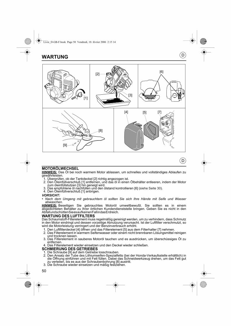
Livre_D-GB-F.book Page 50 Vendredi, 10. février 2006 2:15 14
D
D
WARTUNG
MOTORÖLWECHSELHINWEIS: Das Öl bei noch warmem Motor ablassen, um schnelles und vollständiges Ablaufen zugewâhrleisten.1. Überprüfen, ob der Tankdeckel [2] richtig angezogen ist.2. Den Öleinfüllverschluß [1] entfernen, und das öl in einen Ölbehälter entleeren, indem der Motor
zum öleinfüllstutzen [3] hin geneigt wird.3. Das empfohlene öl nachfüllen und den ölstand kontrollieren [6] (siehe Seite 30).4. Den Öleinfüllverschluß [1] anbrigen.
VORSICHT:• Nach dem Umgeng mit gebrauchtem öl sollten Sie sich Ihre Hände mit Seife und Wasser
abwaschen.HINWEIS: Beseitigen Sie gebrauchtes Motoröl umweltbewußt. Sie sollten es in einemabgedichteten Behälter zu Ihrer örtlichen Kundendienststelle bringen. Geben Sie es nicht in denAbfall und schütten Sie es auf keinen Fall in das Erdreich.WARTUNG DES LUFTFILTERSDas Schaumstoff-Filterelement muss regelmäßig gereinigt werden, um zu verhindern, dass Schmutzin den Motor eindringt und dessen vorzeitige Abnutzung verursacht. Ist der Luftfilter verschmutzt, sowird die Motorleistung verringert und der Benzinverbrauch erhöht.1. Den Luftfilterdeckel [4] öffnen und das Filterelement [5] aus dem Filterhalter [7] nehmen.2. Das Filterelement in warmem Seifenwasser oder einem nicht brennbaren Lösungsmittel reinigen
und trocknen lassen.3. Das Filterelement in sauberes Motoröl tauchen und es ausdrücken, um überschüssiges Öl zu
entfernen.4. Das Filterelement wieder einsetzen und den Deckel wieder schließen.
SCHMIERUNG DES GETRIEBES1. Die Schraube [9] auf dem Getriebe losschrauben.2. Den Ansatz der Tube des Lithiumseifen-Spezialfetts (bei der Honda-Verkaufsstelle erhältlich) in
die Öffnung einführen und mit Fett füllen. Dabei das Schneidwerkzeug drehen, um das Fett gutzu verteilen, bis es aus der Schraubenbohrung [8] austritt.
3. Die Schraube wieder einsetzen und mäßig festziehen.
[1][3]
[2][6]
[9]
[8]
[4] [5] [7]
50

Livre_D-GB-F.book Page 51 Vendredi, 10. février 2006 2:15 14
F ENTRETIENVIDANGE DE L'HUILE MOTEURNOTE : Vidanger l'huile lorsque le moteur est encore chaud afin d'assurer une vidange rapide etcomplète.1. Vérifier si le bouchon du réservoir d'essence [2] est bien fermé.2. Enlever le bouchon de remplissage d'huile [1] et vidanger l'huile dans un récipient approprié en
retournant le moteur du côté du goulot de remplissage d'huile [3].3. Remplir avec l'huile moteur recommandée et vérifier le niveau d'huile [6] (voir page 31).4. Remettre en place le bouchon de remplissage d'huile [1].
PRÉCAUTION:• Se laver les mains avec de l'eau et du savon après avoir manipulé de l'huile usée.NOTE : Prière de jeter l'huile moteur usée conformément aux règles de l'environnement. Nous vousconseillons de la garder dans un bidon fermé et de l'apporter au dépôt le plus proche. Ne pas la jeterà la décharge ou la vider sur le sol.ENTRETIEN DU FILTRE À AIRL'élément filtrant en mousse doit être nettoyé régulièrement pour éviter que les impuretés nepénètrent dans le moteur et ne provoquent une usure prématurée. Un filtre à air sale diminue lapuissance du moteur et augmente la consommation de carburant.1. Ouvrir le capot de filtre à air [4] et sortir l'élément filtrant [5] du porte-filtre [7].2. Le nettoyer à l'eau savonneuse chaude ou dans un solvant ininflammable, puis le laisser sécher.3. Plonger l'élément dans de l'huile moteur propre et le presser pour en extraire l'excédent.4. Replacer l'élément de mousse et le capot de filtre.
GRAISSAGE DU BOÎTIER DE TRANSMISSION1. Dévisser la vis [9] sur le boîtier de transmission.2. Introduire l'embout du tube de graisse spéciale au lithium (disponible auprès de votre revendeur
Honda) et remplir en faisant tourner l'outil de coupe pour bien répartir la graisse, jusqu'à ce qu'elleressorte par l'orifice de la vis [8].
3. Replacer la vis et serrer modérément.
GB MAINTENANCEENGINE OIL CHANGENOTE: Drain the oil while the engine is still warm to assure rapid and complete draining.1. Check the fuel tank cap [2] is tightened.2. Remove the oil filler cap [1] and drain the oil into the oil container by tipping the engine toward the
oil [3] filler neck.3. Refill with the recommended and check the oil level [6] (see page 31).4. Install the oil filler cap [1].
CAUTION:• Wash your hands with soap and water after handling used oil.NOTE: Please dispose of used motor oil in a manner that is compatible with the environnement. Wesuggest you take it in a sealed container to your local service station for reclamation. Do not throw itin the trash or pour it on the ground.AIR CLEANER MAINTENANCEThe foam air filter element must be cleaned regularly to prevent impurities from entering the engineand causing premature wear. A dirty air filter will reduce engine power and increase fuelconsumption.1. Open the air filter cover [4] and remove the filter [5] from the filter housing [7].2. Clean the filter with warm soapy water or in a nonflammable solvent and then leave to dry.3. Dip the element in clean engine oil and squeeze out the excess oil.4. Reinstall the foam filter element and the filter cover.
LUBRICATING THE TRANSMISSION HEAD1. Remove the bolt [9] from the transmission head.2. Insert the nozzle of the tube of special lithium grease (available from your Honda dealer) and fill
with grease while turning the cutting attachment so that the grease is properly distributed.Continue until grease comes out of the bolt hole [8].
3. Reinstall the bolt and tighten moderately.
51

Livre_D-GB-F.book Page 52 Vendredi, 10. février 2006 2:15 14
WARTUNGWARTUNGSZEITPLAN
* Häufigkeit: Die Arbeiten sind nach dem kürzeren der beiden durch Betriebsstunden oder Zeitgegebenen Intervalle durchzuführen.
(1) In staubiger Umgebung öfter reinigen.(2) Diese Arbeiten sollten bei der nächsten zugelassenen Honda-Verkaufsstelle durchgeführt
werden, außer für den Fall, dass der Besitzer über die geeigneten Werkzeuge und die zurDurchführung solcher Arbeiten erforderliche technische Ausbildung verfügt. Auf die Honda-Werkstattanleitung Bezug nehmen.
Baugruppe Arbeit
Häufigkeit*
Vor jedem
Einsatz
Nach 1 Monat oder
nach 10 Stunden
Nach 3 Monaten
oder nach 25 Stunden
Nach 6 Monaten
oder nach 50 Stunden
jährlich oder alle
100 Stunden
Kühlrippen des Motors Reinigen
Mähwerkzeug und dessen Schutzabdeckung Prüfen
Umgebung des Antriebskopfs Reinigen
Antriebskopf Prüfen
Gashebel, Arbeitsweise Schmieren
Stop-Schalter, Arbeitsweise Prüfen
Leerlauf / Kupplung Prüfen
Luftfilter-EinsatzPrüfen
Reinigen (1)
Luftfilter-Gehäuse Reinigen (1)
Umgebung der Zündkerze Reinigen
ZündkerzePrüfen
Reinigen
Umgebung des Vergasers Reinigen
Kabel und Anschlüsse Prüfen
Benzinleitungen Prüfen alle 2 Jahre (wenn nötig, ersetzen) (2)
Benzinfilter Prüfen (2)
Feder und Schuhe der Kupplung Prüfen (2)
LeerlaufPrüfen (2)
Einstellen (2)
MotorölPrüfen
Wechseln nach 10 Betriebsstunden und dann alle6 Monate oder 50 Betriebsstunden
Kraftstofftank Reinigen
Ventilspiel Einstellen (2)
Schrauben und Muttern Prüfen / nachziehen
D
52

Livre_D-GB-F.book Page 53 Vendredi, 10. février 2006 2:15 14
MAINTENANCEMAINTENANCE SCHEDULE
* Frequency: Maintenance to be performed at the intervals specified in service hours or periods oftime, whichever is shorter.
(1) Clean more often in dusty environments.(2) These operations should be performed by an authorized Honda dealer, unless the owner has the
appropriate tools and technical know-how required. Refer to the Honda workshop manual.
Item Servicing action
Frequency*
Each time used
Every month or 10 hours
Every 3 months
or 25 hours
Every 6 months
or 50 hours
Every year or
100 hours
Engine cooling fins Clean
Condition of cutting attachment and guard Check
Zone around transmission head Clean
Transmission head Grease
Operation of throttle trigger Check
Operation of Stop button Check
Idle / Clutch Check
Air filter elementCheck
Clean (1)
Air filter housing Clean (1)
Zone around spark plug Clean
Spark plugCheck
Clean
Zone around carburettor Clean
Cables and connections Check
Fuel system Check Every 2 years (replace if necessary) (2)
Fuel filter Check (2)
Spring and clutch pads Check (2)
Idle speedCheck (2)
Adjust (2)
Engine oilCheck
Replace Replace after 10 service hours and then every6 months or 50 service hours
Fuel tank Clean
Valve clearance Adjust (2)
Nuts and bolts Check / Tighten
GB
53

Livre_D-GB-F.book Page 54 Vendredi, 10. février 2006 2:15 14
ENTRETIENCALENDRIER D’ENTRETIEN
* Périodicité : Entretien à effectuer aux intervalles indiqués en heures de fonctionnement oupériodes, en retenant l'intervalle le plus court.
(1) Nettoyer plus fréquemment en milieu poussiéreux.(2) Ces travaux devraient être effectués par votre revendeur agréé Honda, à moins que le
propriétaire ait des outils appropriés et l'instruction technique requise pour ce travail. Se référerau manuel d'atelier Honda.
Elément Intervention
Périodicité*A
chaque utili-
sation
Tous les mois ou
10 heures
Tous les 3 mois ou 25
heures
Tous les 6 mois ou 50
heures
Tous les ans ou
100 heures
Ailettes de refroidissement moteur Nettoyer
Etat de l'outil et duprotecteur Vérifier
Abords de la tête de transmission Nettoyer
Tête de transmission Graisser
Fonctionnement de lagâchette des gaz Vérifier
Fonctionnement dubouton d'arrêt Vérifier
Ralenti / Embrayage Vérifier
Elément de Filtre à airVérifier
Nettoyer (1)
Boîtier de Filtre à air Nettoyer (1)
Abords de la bougie Nettoyer
BougieVérifier
Nettoyer
Abords du carburateur Nettoyer
Câbles et connexions Vérifier
Circuit d'essence Vérifier Tous les 2 ans (remplacer si nécessaire) (2)
Filtre à essence Vérifier (2)
Ressort et patins d'embrayage Vérifier (2)
RalentiVérifier (2)
Régler (2)
Huile moteurVérifier
Remplacer Remplacer après 10 heures et ensuite tous les6 mois ou 50 heures
Réservoir de carburant Nettoyer
Jeu aux soupapes Régler (2)
Vis et écrous Vérifier / resserrer
F
54

Livre_D-GB-F.book Page 55 Vendredi, 10. février 2006 2:15 14
FEHLERSUCHEVorfall Mögliche Ursache Seite
Der Motor startet nicht. 1. Der Tank ist leer. 282. Der Stop-Schalter befindet sich auf Position Stop. 323. Das Zündkerzenstecker ist schlecht oder nicht
angeschlossen.48
4. Die Zündkerze ist durchgebrannt oder ihrElektrodenabstand ist falsch
48
5. Der Motor ist "abgesoffen". Die Zündkerze entfernen,mit einem Lappen trocknen und wieder einbauen.
48
6. Der Benzinfilter ist verschmutzt. Ihn reinigen. -
Der Motor startet schwer. 1. Der Luftfilter ist verschmutzt. 502. Es befindet sich Schmutz im Benzintank oder die
Motorleistung ist abgefallen.-
3. Es befindet sich Wasser im Kraftstofftank und imBenzin.
-
4. Die Druckausgleichöffnung des Kraftstofftanks und/oder der Vergaser sind verschmutzt.
-
5. Der Motor ist warm und der Starter ist geschlossen. DenStarter öffnen.
34
Der Betrieb istunregelmäßig.
1. Die Zündkerze ist fehlerhaft oder ihr Elektrodenabstandist falsch.
48
2. Der Luftfilter ist verschmutzt. 50
Der Motor erwärmtsich übermäßig.
1. Der Elektrodenabstand der Zündkerze ist falsch.
48
2. Der Luftfilter ist verschmutzt. 503. Die Kühlrippen des Motors sind verschmutzt. -4. Der Ölstand ist unzureichend. 305. Die Starterscheibe ist durch Grashalme oder ähnliches
verschmutzt.
Die Motorsense schwingt auf übermäßige Weise.
1. Das Mähwerkzeug ist schlecht ausgewuchtet oderfalsch montiert.
18
2. Die Schrauben des Motors haben sich gelöst. -
D
55

Livre_D-GB-F.book Page 56 Vendredi, 10. février 2006 2:15 14
TROUBLESHOOTINGProblem Probable cause Page
Engine does not start. 1. No fuel. 29
2. Start/Stop button is in Stop position. 33
3. Spark plug cap incorrectly attached or disconnected. 49
4. Faulty spark plug or incorrect gap. 49
5. Engine flooded. Remove spark plug, dry it with a clothand reinstall it.
49
6. Fuel filter is dirty. Clean it. -
Starting difficult or lossof power.
1. Dirty air filter. 51
2. Impurities in fuel tank. -
3. Water in fuel tank and in fuel -
4. Fuel tank cap vent and /or carburettor clogged. -
5. Engine is hot; choke is closed. Open choke. 35
Uneven running. 1. Faulty spark plug or incorrect gap. 49
2. Dirty air filter. 51
Engine overheats. 1. Spark plug gap incorrect. 49
2. Dirty air filter. 51
3. Engine cooling fins clogged. -
4. Oil level too low. 31
5. Starter pulley fouled by grass cuttings, etc. -
Brush cutter vibrates excessively.
1. Blade incorrectly balanced or cutting attachmentincorrectly fitted.
19
2. Engine bolts loose. -
GB
56

Livre_D-GB-F.book Page 57 Vendredi, 10. février 2006 2:15 14
DÉPISTAGE DES PANNESIncident Cause probable Page
Le moteur ne démarre pas. 1. Il n'y a pas d'essence. 292. Le bouton marche/arrêt est en position arrêt . 333. Le capuchon de la bougie d'allumage est mal fixé ou
débranché.49
4. La bougie d'allumage est défectueuse ou l'écartementdes électrodes est incorrect.
49
5. Le moteur est noyé. Retirer la bougie, la sécher avec unchiffon. Remonter la bougie.
49
6. Le filtre à essence est sale, le nettoyer. -
Le démarrage est difficile. 1. Le filtre à air est sale. 512. Il y a des impuretés dans le réservoir d'essence ou il y
a perte de puissance.-
3. Il y a de l'eau dans le réservoir d'essence ainsi que dansle carburant.
-
4. L'évent dans le bouchon du réservoir d'essence et/ou lecarburateur est encrassé.
-
5. Le moteur est chaud, le starter est fermé. Ouvrir lestarter.
35
Le fonctionnement est irrégulier.
1. La bougie d'allumage est défectueuse ou l'écartementdes électrodes est incorrect.
49
2. Le filtre à air est sale. 51
Le moteur chauffe anormalement.
1. L'écartement des électrodes de la bougie d'allumageest incorrect.
49
2. Le filtre à air est sale. 513. Les ailettes de refroidissement du moteur sont
encrassées.-
4. Le niveau d'huile est insuffisant. 315. La poulie du lanceur est encrassée par des brins
d'herbe, etc.-
Le coupe-bordure vibrede manière excessive.
1. Lame déséquilibrée ou outil mal monté. 192. Les vis du moteur sont dessérrées. -
F
57

Livre_D-GB-F.book Page 58 Vendredi, 10. février 2006 2:15 14
D
D
TRANSPORT UND LAGERUNG
TRANSPORT
Zum Transport der Motorsense muss unbedingt der Motor abgestellt und derTransportschutz über dem Mähwerkzeug angebracht werden.Das Gerät zum Transport in ausgeglichener Weise am Antriebsrohr halten. Soll die Motorsense ineinem Fahrzeug transportiert werden, so ist sicherzustellen, dass sie richtig gehalten wird und sichnicht bewegen kann. Sie muss so abgelegt werden, dass kein Kraftstoff auslaufen kann.LAGERUNGSoll das Gerät während eines Zeitraums von über zwei Monatennichtbenutzt werden, so ist es angebracht, zur Lagerung die folgendenVorsichtsmaßnahmen zu ergreifen:- Den Kraftstofftank leeren und den Motor drehen lassen, so dass auch
der Vergaser geleert wird.- Die Zündkerze abmontieren und einige Tropfen Öl (gleicher Sorte wie das im motor verwendete)
gießen.- Vorsichtig den Starter ziehen, um das Öl auf den Wänden des Zylinders und des Kolbens zu
verteilen, und die Zündkerze wieder montieren.- Das ganze Gerät reinigen. Insbesondere sind Grasablagerungen um das Mähwerkzeug, in den
Kühlrippen des Motors und unter den Verkleidungen zu entfernen.- Mit einem Pinsel eine dünne Schicht Standardöl auf den Metallwerkzeugen auftragen, um deren
Korrosion vorzubeugen.- Das Gerät in seiner Verpackung an einem kühlen und trockenen Ort aufbewahren.- Wenn das Gerät stehend eingeräumt werden muss, ist es mit dem Motor nach unten so
abzustellen, dass es nicht umkippen kann.
SICHERHEITD8 D10
C12 D1 D4
58

GB TRANSPORT AND STORAGETRANSPORT
When transporting or carrying your brush cutter, the engine must always be stopped and thetransport guard must be installed on the cutting attachment.When carrying your brush cutter, hold it by the transmission tube in a balanced position.If it is to betransported in a vehicle, make sure that it is properly secured so it cannot move. It must be positionedso that there is no risk of fuel leakage.
STORAGEIf the machine is not to be used for more than two months, the followingstorage precautions should be taken:- Drain the fuel tank and run the engine to empty the carburettor.- Remove the spark plug and pour a few drops of oil (same quality as that
used in the engine) into the cylinder.- Gently pull the recoil starter to distribute the oil in the cylinder and on the piston. Then reinstall the
spark plug.- Clean the whole machine, paying special attention to plant residues accumulated around the
cutting attachment, in the engine cooling fins and under the cowlings.- Using a paint brush, apply a thin film of standard oil over the metal cutting attachments to prevent
corrosion.- Store the machine in its packaging, in a cool dry place.- If the machine is to be stored in a vertical position, place it with the engine at the bottom so that it
will not topple over.
SAFETYD8 D10
C12 D1 D4
Livre_D-GB-F.book Page 59 Vendredi, 10. février 2006 2:15 14
F TRANSPORT ET REMISAGETRANSPORT
Pour transporter la débroussailleuse, il faut systématiquement arrêter le moteur et placer leprotecteur de transport sur l'outil.Pour transporter l'outil, le tenir par le tube de transmission de façon à ce qu'il soit équilibré. Si lamachine doit être transportée à bord d'un véhicule, il faut s'assurer qu'elle est correctementmaintenue, afin d'empêcher tout mouvement. Elle doit être posée de manière à ne pas provoquerde fuite de carburant.REMISAGELorsque la machine doit rester inutilisée pour une période supérieure àdeux mois, il convient de prendre les précautions suivantes pour lestockage :- Vidanger le réservoir de carburant et faire tourner le moteur pour vider
le carburateur.- Démonter la bougie et verser quelques gouttes d'huile (même qualité que celle utilisée dans le
moteur).- Tirer doucement sur le lanceur pour répartir l'huile sur les parois du cylindre et du piston, puis
replacer la bougie.- Nettoyer l'ensemble de la machine, particulièrement les accumulations de débris végétaux autour
de l'outil, dans les ailettes de refroidissement du moteur et sous les capotages.- Déposer une fine pellicule d'huile standard, à l'aide d'un pinceau, sur les outils métalliques pour
prévenir la corrosion.- Ranger la machine dans son emballage, dans un endroit sec et frais.- Si la machine doit être rangée debout, la placer avec le moteur en bas et veiller à ce qu'elle ne
puisse pas basculer.
SECURITE D8 D10
C12 D1 D4
59

Livre_D-GB-F.book Page 60 Vendredi, 10. février 2006 2:15 14
D
D
ZUBEHÖR
Mit dem Gerät wird verschiedenes Zubehör geliefert oder ist, je nach Modell, als Option verfügbar.In Tabelle sind die an den einzelnen Modelle montierbaren Ausstattungen zusammengestellt:
[1] Mähen und Reinigen[2] Dornige Hecken und Gestrüpp[3] Große Grasflächen[4] Hohes und trockenes Gras[5] Holziges Gestrüpp und Sträucher (als Option für die Typen UMK435E UEET)[6] Zur Montage der Messer [2], [3] und [4] erforderliche Ausstattungen[7] Lichten von Hecken und Bäumen
OptionStandardVerboten
UM
K42
5E /
UM
K43
5E
[1] [2] [3] [4] [5] [6] [7]
LEET
UEET
SICHERHEITA2 D3
UMK425E
UMK435E
UMK425E
UMK435E
60

GB ACCESSORIESVarious accessories are supplied with the machine or are available as options, depending on themodel.The accessories that can be fitted on the various models are indicated in the table:
[1] Mowing and clearing[2] Thorny hedges and brush[3] Large areas of grass[4] Tall dry grass[5] Knotty brush and bushes (optional for types UMK435E UEET)[6] Device required to fit cutters [2], [3] and [4][7] Pruning of trees and bushes
OptionalStandardProhibited SAFETY
A2 D3
Livre_D-GB-F.book Page 61 Vendredi, 10. février 2006 2:15 14
F ACCESSOIRESDivers accessoires sont livrés avec la machine ou sont disponibles en option, selon les modèles.Le tableau résume les possibilités de montage en fonction des modèles :
[1] Fauchage et nettoyage[2] Haie épineuses et broussailles[3] Grandes surfaces d'herbes[4] Herbes hautes et sèches[5] Broussailles noueuses et arbustes (en option pour les UMK435E UEET)[6] Dispositif nécessaire au montage des couteaux [2], [3] et [4][7] Elagage d'arbres et d'arbustes
OptionStandardInterdit SAFETY
A2 D3
61

Livre_D-GB-F.book Page 62 Vendredi, 10. février 2006 2:15 14
TECHNISCHE DATEN
MODELLENUMK425E UMK435E
LEET UEET LEET UEETTypenbezeichung HADF HAFF
Abmessungen L x B x H mm 1 770 x368 x 305
1 770 x670 x 488
1 790 x368 x 305
1 790 x670 x 488
Motor GX25 GX35Hubraum cm3 25 35,8Bohrung/Hub mm 35 x 26 39 x 30Leistung (gemäßEN11806) kW 0,81 1,20
Maximale DrehzahlU/min. 10 000 10 000Leerlaufdrehzahl U/min. 3 100 ± 200Motoröl SAE 10W30Fassungsvermögendes Ölbehälters cm3 80 100
Benzin BleifreiFassungsvermögen desKraftstofftanks l
0,55 0,65
Zündung Transistor-MagnetzündungMarke und Art der Zündkerze NGK CM5H NGK CMRSHVergaser MembraneAntriebsrohr Ø mm 26Antriebswelle mm 7Anzahl der Wälzlager 7Kupplungsglocke Ø mm 54 78Getriebe Spiralkegelrad-WinkelgetriebeÜbersetzungsverhältnis 15 / 20 17 / 22Drehzahl des Mähwerkzeugs(motor) U/min. 5 250 / (7 000) 5 409 / (7 000)
Länge des Nylonfadens mitØ 2,7 (standard) m 5,5
Länge des Nylonfadens mitØ 2,4 (option) m 7
Leergewicht kg 5,20 5,43 6,38 6,62
LEET UEET LEET UEET
Schalldruck in Bedienposition (gemäß EN ISO11806)dB(A) 97,4 94,3 93,4 91,2 95,9 93,2 93,7 93,7
Schwingungsniveau (gemäß der Norm ISO7916)
Leerlaufdrehzahl m/s22,3 3,1 1,3 2,8 2,7 2,3 4,4 3,8
Max. m/s2 11,6 11,7 7,3 8,1 9,8 9,8 7,0 7,3Garantierter Geräuschpegel (gemäß EG-Richtlinie2000/14/EC) dB(A)
111 112
D
GEBRUCKT IN ITALY
62

Livre_D-GB-F.book Page 63 Vendredi, 10. février 2006 2:15 14
TECHNICAL SPECIFICATIONS
MODELSUMK425E UMK435E
LEET UEET LEET UEETDescription code HADF HAFF
Dimensions L x W x h mm 1 770 x368 x 305
1 770 x670 x 488
1 790 x368 x 305
1 790 x670 x 488
Engine GX25 GX35Displacement cm3 25 35,8Bore / Stroke mm 35 x 26 39 x 30Power (as per EN11806) kW 0.81 1.20Maximum speed rpm 10 000 10 000Idle speed rpm 3 100 ± 200Engine oil SAE 10W30Oil tank capacity cm3 80 100Fuel UnleadedFuel tank capacity l 0.55 0.65Ignition Transistorized magneto ignitionSpark plug brand and type NGK CM5H NGK CMRSHCarburettor MembraneTransmission tube Ø mm 26Drive shaft mm 7Number of bearings 7Clutch housing Ø mm 54 78Transmission Helical-toothed bevel gearGear ratio 15 / 20 17 / 22Cutting attachmentrotation speed / motor rpm 5 250 / (7 000) 5 409 / (7 000)
Length of nylon lineØ 2.7 (standard) m 5.5
Length of nylon lin Ø 2.4 (optional) m 7
Empty weight kg 5.20 5.43 6.38 6.62
LEET UEET LEET UEET
Sound pressure level in operator's ears (as per standard EN ISO11806)dB(A)
97,4 94,3 93,4 91,2 95,9 93,2 93,7 93,7
Vibration level (as perstandard ISO7916)
idle m/s22,3 3,1 1,3 2,8 2,7 2,3 4,4 3,8
Max. m/s2 11,6 11,7 7,3 8,1 9,8 9,8 7,0 7,3Guaranteed sound powerlevel (as per directive2000/14/EC) dB(A)
111 112
GB
PRINTED IN ITALY
63
Livre_D-GB-F.book Page 64 Vendredi, 10. février 2006 2:15 14
SPÉCIFICATIONS TECHNIQUES
MODÈLESUMK425E UMK435E
LEET UEET LEET UEETCode de description HADF HAFF
Dimensions L x l x h mm 1 770 x368 x 305
1 770 x670 x 488
1 790 x368 x 305
1 790 x670 x 488
Moteur GX25 GX35Cylindrée cm3 25 35,8Alésage / Course mm 35 x 26 39 x 30Puissance (selon EN11806)
kW 0,81 1,20
Régime maximum tr/min. 10 000 10 000Ralenti tr/min. 3 100 ± 200Huile moteur SAE 10W30Capacité du réservoird'huile cm3 80 100
Essence Sans plombCapacité du réservoir d'essence l
0,55 0,65
Allumage Magneto-transistoriséMarque et type de bougie NGK CM5H NGK CMRSHCarburateur MembraneTube de transmission Ø mm 26Arbre d'entraînement mm 7Nombre de roulement 7Cloche d'embrayage Ø mm 54 78Transmission Renvoi d'angle conique à dents hélicoïdalesRapport de transmission 15 / 20 17 / 22Vitesse de rotation de l'outilde coupe / moteur tr/min. 5 250 / (7 000) 5 409 / (7 000)
Longueur de fil de nylonavec Ø 2,7 (standard) m 5,5
Longueur de fil de nylonavec Ø 2,4 (option) m 7
Poids à vide kg 5,20 5,43 6,38 6,62
LEET UEET LEET UEET
Niveau de pression acoustique au poste de conduite (Selonnorme EN ISO11806) dB(A)
97,4 94,3 93,4 91,2 95,9 93,2 93,7 93,7
Niveau de vibration (Selon la norme ISO7916)
ralenti m/s22,3 3,1 1,3 2,8 2,7 2,3 4,4 3,8
Max. m/s2 11,6 11,7 7,3 8,1 9,8 9,8 7,0 7,3Niveau de puissance acoustique garanti (Selon directive 2000/14/CE) dB(A)
111 112
F
IMPRIMÉ EN ITALY3C VJ5 F13 0206 - 1
RC
S O
RLÉ
AN
S B
332
855
402
64

64
ESPECIFICACIONES TÉCNICAS
MODELOSUMK425EUMK435ELEETUEETLEETUEET
Código de descripciónHADFHAFF
Dimensiones L x A x Amm1 770 x368 x 305
1 770 x670 x 488
1 790 x368 x 305
1 790 x670 x 488
MotorGX25GX35Cilindradacm32535,8Ø int./Carreramm35 x 2639 x 30Potencia (segúnEN11806)kW0,811,20
Régimen máximoRev./min.10 00010 000RalentíRev./min.3 100 ± 200Aceite motorSAE 10W30Capacidad del depósitode aceitecm380100
Gasolinasin plomoCapacidad del depósitode gasolinal0,550,65
EncendidoMagneto-transistorizadoMarca y tipo de bujíaNGK CM5HNGK CMRSHCarburadorMembranaTubo de transmisiónØ mm26Árbol de accionamientomm7Número de rodamientos7Campana de embrague
Ø mm5478
TransmisiónTransmisión en ángulo cónico con dientes helicoidalesRelación de transmisión15 / 2017 / 22Velocidad de rotación dela herramienta de corte
Rev./min.5 250 / (7 000)5 409 / (7 000)
Longitud del hilo de nylon con Ø 2,7 (standard)m5,5
Longitud del hilo de nylon conØ 2,4 (option)m7
Peso en vacíokg5,205,436,386,62
LEETUEETLEETUEET
Nivel de pressión acústica al puesto de conducto (según norma EN ISO11806)dB(A
97,494,393,491,295,993,293,793,7
Nivel de vibración (según la norma ISO7916)
mínimom/s22,33,11,32,82,72,34,43,8
Max.m/s211,611,77,38,19,89,87,07,3Nivel de potencia acústica garantizado (según directiva 2000/14/EC)dB(A)
111112
E
3C VJ5 F13IMPRESO EN ITALIA0206 - 1
RC
S OR
LÉAN
S B 332 855 402
Livre_I-NL-E.book Page 64 Vendredi, 10. février 2006 2:30 14

63
TECHNISCHE GEGEVENS
MODELSUMK425EUMK435E
LEETUEETLEETUEETType codeHADFHAFF
Afmetingen L x H x Bmm1 770 x368 x 305
1 770 x670 x 488
1 790 x368 x 305
1 790 x670 x 488
MotorGX25GX35Cilinderinhoud,cm32535,8Boring/slagmm35 x 2639 x 30Vermogen (vlgsEN11806)kW0,811,20
MaximumtoerentalOmw./min.10 00010 000
Stationair toerentalOmw./min.3 100 ± 200
MotorolieSAE 10W30Inhoud oliecartercm380100BenzineZonder loodInhoud benzinetankl0,550,65OntstekingTransistor-magnetMerk en type bougieNGK CM5HNGK CMRSHCarburateurMembraanDiameter transmissiebuis
Ø mm26
Aandrijfasmm7Aantal lagers7Diameter koppelingsdeksel
Ø mm5478
TransmissieHaakse overbrengingTransmissieverhouding15 / 2017 / 22Toerental snijgereedschap
Omw./min.5 250 / (7 000)5 409 / (7 000)
Lengte nylonsnoer SnoerØ 2,7 (standaard)m5,5
Lengte nylonsnoer SnoerØ 2,4 (optie)m7
Ledig gewichtkg5,205,436,386,62
LEETUEETLEETUEET
Geluidsdrukniveau op de bedieningsplaats (Richtlijn EN ISO11806)dB(A
97,494,393,491,295,993,293,793,7
Trillingsviveau (vlgs ISO7916) Stationairtoerentalm/s22,33,11,32,82,72,34,43,8
Max.m/s211,611,77,38,19,89,87,07,3Gewaarborgd geluidsemissieniveau (Richtlijn 2000/14/EC)dB(A)
111112
NL
GEDRUCKT IN ITALY
Livre_I-NL-E.book Page 63 Vendredi, 10. février 2006 2:30 14

62
SPECIFICHE TECNICHE
MODELLIUMK425EUMK435E
LEETUEETLEETUEETCodice descrittivoHADFHAFF
Dimensioni L x l x hmm1 770 x368 x 305
1 770 x670 x 488
1 790 x368 x 305
1 790 x670 x 488
MotoreGX25GX35Cilindratacm32535,8Alesaggio/Corsa mm35 x 2639 x 30Potenza (secondoEN11806)kW0,811,20
Velocità massimagiri/min.10 00010 000Minimogiri/min.3 100 ± 200Olio motoreSAE 10W30Capacità del serbatoiooliocm380100
BenzinaPreferibilmente senza piomboCapacità del serbatoio benzina
l0,550,65
AccensioneMagnetica transistorizzataMarca e tipo di candelaNGK CM5HNGK CMRSHCarburatoreMembranaTubo di trasmissioneØ mm26Albero motore mm7Numero di rotazioni7Campana Ø mm5478TrasmissioneRinvio d'angolo conico a denti elicoidaliRapporto di trasmissione15 / 2017 / 22Velocità di rotazione dell’attrezzo di taglio
giri/min.5 250 / (7 000)5 409 / (7 000)
Lunghezza filo di nylonØ 2,7 (standard)m5,5
Lunghezza filo di nylonØ 2,4 (optional)m7
Peso a vuotokg5,205,436,386,62
LEETUEETLEETUEET
Livello di pressione acustica al posto di guida (secondo norma EN ISO11806)dB(A)
97,494,393,491,295,993,293,793,7
Livello di vibrazione (secondo norma ISO7916)
minimom/s22,33,11,32,82,72,34,43,8
Max.m/s211,611,77,38,19,89,87,07,3Livello di potenza acustica garantito (secondo direttiva 2000/14/EC)dB(A)
111112
I
STAMPATO IN ITALIA
Livre_I-NL-E.book Page 62 Vendredi, 10. février 2006 2:30 14

61
Con la máquina se suministran varios accesorios, habiendo otros que están disponiblesopcionalmente, según los modelos.En la siguiente tabla se resumen las posibilidades de montaje según el modelo:
[1]Desbroce y limpieza[2]Seto de espinas y maleza[3]Grandes áreas de hierbas[4]Hierbas altas y secas[5]Maleza zarzal y arbustos (opcional, para los modelos UMK435E UEET)[6]Dispositivo necesario para montar las cuchillas [2] [3] y [4] [7]Poda de árboles y arbustos
OpcionalEstándarProhibidoSEGURIDADA2D3
GB
FACCESORIOS
ACCESSOIRESAfhankelijk van model worden bepaalde accessoires standaard meegeleverd. Alle accessoireskunnen worden nabesteld. Zie onderstaande tabel:
[1]Gras en onkruid, kaalslag[2]Doornheggen en struikgewas[3]Grote grasoppervlakken[4]Hard gras, droog gras, riet[5]Hout, onderhout, kreupelhout (optie voor de UMK435E UEET)[6]Montagehulpstuk voor messen [2] [3] [4][7]Snoeien van bomen en struiken
OptieStandaardVerbodenSICHERHEITA2D3
Livre_I-NL-E.book Page 61 Vendredi, 10. février 2006 2:30 14

60
D
D
ACCESSORI
Diversi accessori sono in dotazione con la macchina oppure disponibili come optional, secondo imodelli.La tabella riporta un sommario delle possibilità di montaggio in funzione dei modelli:
[1]Falciatura e pulizia[2]Siepi con spine e cespugli[3]Ampie superfici erbose[4]Erba alta e secca[5]Cespugli nodosi e arbusti (optional per UMK435E UEET)[6]Dispositivo necessario per il montaggio dei coltelli [2], [3] e [4][7]Potatura di alberi e arbusti
OptionalStandardVietato
UM
K425E / U
MK
435E
[1][2][3][4][5][6][7]
LEET
UEET
SICUREZZAA2D3
UMK425E
UMK435EUMK425E
UMK435E
Livre_I-NL-E.book Page 60 Vendredi, 10. février 2006 2:30 14

59
TRANSPORTAR
Para transportar la desbrozadora, hay que apagar sistemáticamente su motor y colocar elprotector de transporte en la herramienta de corte.Para trasportar la máquina, manténgala por el tubo de transmisión para que esté equilibrada. Si lamáquina debe transportarse a bordo de un vehículo, hay que estar seguros que está sujetacorrectamente, con el fin de impedir cualquier movimiento. Debe colocarse de manera que noprovoque fuga de carburante.
GUARDARCuando la máquina tenga que quedar sin trabajar durante un periodosuperior a dos meses, es conveniente tomar las precauciones siguientespara guardarla:-Vacíe el depósito de gasolina y encienda el motor hasta que se apague por sí solo.-Desmonte la bujía y vierta algunas gotas de aceite (misma calidad que el utilizado en el motor).-Tire suavemente del lanzador para repartir el aceite por las paredes del cilindro y del pistón, y
vuelva a montar la bujía.-Limpie toda la máquina, sacando especialmente los restos de vegetales que adhieran alrededor
de la herramienta, en las aletas de refrigeración del motor y bajo las tapas.-Ponga una pequeña capa de aceite normal, mediante un pincel, en las herramientas metálicas
para prevenir la corrosión.-Guarde la máquina en su embalaje, en un lugar seco y fresco.-Si la máquina debe quedar guardada de pie, colóquela con el motor abajo y trate de que no caiga.
SEGURIDADD8D10
C12D1D4
GB
FTRANSPORTAR Y GUARDAR
VERVOER EN OPSLAGVERVOER
Vervoer of draag alleen een uitgeschakelde machine met de beschermkap op het mes of detrimmerkop.Dragen: In het midden van het aandrijfashuis vastnemen, en in evenwicht houden. Vervoeren: Goedvastbinden en voorkomen dat er benzine uitlekt.
OPSLAGWanneer de machine langer dan 2 maanden opgeborgen wordt, moet hetonderstaande onderhoud worden uitgevoerd:-Benzinetank ledigen en motor laten draaien tot de carburateur droogvalt.-Bougie verwijderen en een paar druppels olie op de zuiger gieten (dezelfde olie als die in het
oliecarter).-Langzaam aan het starterkoord trekken op de olie over de cilinder- en zuigerwanden te verdelen
en bougie in de cilinderkop schroeven.-Plantaardig en ander vuil verwijderen (koelribben, transmissiekop, onder de beplating).-Blanke delen inoliën.-Machine in fabrieksverpakking en droog en koel opbergen.-Bij staand opgeborgen machine: Motor onderaan en machine voor omvallen behoeden.
SICHERHEITD8D10
C12D1D4
Livre_I-NL-E.book Page 59 Vendredi, 10. février 2006 2:30 14

58
D
D
TRASPORTO E DEPOSIT
TRASPORTO
Per trasportare il decespugliatore, è necessario arrestare sistematicamente il motore eposizionare la protezione da trasporto sull'attrezzo.Durante il trasporto, reggere l'attrezzo dal tubo di trasmissione in modo che resti bilanciato. Se iltrasporto della macchina avviene a bordo di un veicolo, accertare che sia bloccata correttamente, inmodo da evitare qualsiasi movimento, e posizionata in modo da prevenire eventuali fuoriuscite dicarburante.DEPOSITOSe la macchina resta inutilizzata per un periodo superiore a due mesi, èconsigliabile adottare le seguenti precauzioni per il suo stoccaggio:-Svuotare il serbatoio del carburante e far girare il motore per svuotare il
carburatore.-Smontare la candela e versare qualche goccia di olio (della stessa
qualità di quello utilizzato per il motore).-Tirare delicatamente l'avviamento a corda per distribuire l'olio sulle pareti del cilindro e del pistone,
quindi riposizionare la candela.-Pulire interamente la macchina, in particolare gli accumuli di scorie vegetali attorno all'attrezzo,
nelle alette di raffreddamento del motore e sotto le carenature.-Con una pennello, spargere uno strato sottile di olio standard sugli attrezzi metallici per prevenire
la corrosione.-Riporre la macchina nell'imballaggio in un luogo fresco e asciutto.-Se la macchina deve essere riposta in posizione verticale, sistemarla con il motore in basso e
verificare che non oscilli.
SICUREZZAD8D10
C12D1D4
Livre_I-NL-E.book Page 58 Vendredi, 10. février 2006 2:30 14

57
DETECCIÓN DE AVERÍASProblemaCausa probablePágina
El motor no enciende1.No hay gasolina.292.El botón marcha / parada está en parada333.El hilo de la bujía está mal fijado o desconectado494.La bujía está defectuosa o los electrodos no están bien
separados.49
5.El motor está ahogado. Saque la bujía, séquela con untrapo. Móntela.49
6.El filtro de gasolina está sucio, límpielo.-
El encendido es difícil1.El filtro de aire está sucio.512.Hay impurezas en el depósito de gasolina o pérdida de
gasolina.-
3.Hay agua en el depósito de gasolina y en el carburante.-4.El respiradero en el tapón del depósito de gasolina está
atascado.-
5.El motor está caliente, el estárter está cerrado. Abra elestárter.35
El funcionamiento es irregular
1.La bujía está defectuosa o los electrodos están malseparados.49
2.El filtro de aire está sucio.51
El motor se recalienta anormalmente
1.La separación de los electrodos de la bujía esincorrecta.49
2.El filtro de aire está sucio.513.Las aletas de refrigeración del motor están sucias.-4.El nivel de aceite es insuficiente.315.La polea del lanzador tiene trozos de hierba, etc.-
La desbrozadora vibra de manera excesiva
1.La cuchilla está desequilibrada o el cabezal malmontado.19
2.Los tornillos del motor están mal apretados.-
E
Livre_I-NL-E.book Page 57 Vendredi, 10. février 2006 2:30 14

56
STORINGZOEKENSymptoomWaarschijnlijke oorzaakBladzijde
Motor start niet1.Geen benzine.29
2.Stopknop op STOP.33
3.Bougiekabel kapot of los.49
4.Bougie defect of elektrodenafstand te groot.49
5.Motor verzopen. Bougie demonteren en drogen.49
6.Benzinefilter vervuild - reinigen.-
Machine start moeilijk1.Luchtfilter vervuild.51
2.Vuil in de benzine of gebrek aan vermogen.-
3.Water in de benzine.-
4.Ontluchtopening in benzinetank of carburateurverstopt.-
5.Motor warm en choke dicht. Choke openen.35
Motor loopt onregelmatig1.Bougie defect of elektrodenafstand te groot.49
2.Luchtfilter vervuild.51
Motor loopt warm1.Elektrodenafstand te groot.49
2.Luchtfilter vervuild.51
3.Koelribben motorblok vervuild.-
4.Gebrek aan olie.31
5.Pulley starterkoord vervuild.-
Machine trilt hevig1.Mes uit balans of verkeerd gemonteerd.19
2.Losse motorbevestigingsbouten.-
NL
Livre_I-NL-E.book Page 56 Vendredi, 10. février 2006 2:30 14

55
RICERCA GUASTIProblemaCausa probabilePagina
Il motore non si avvia1.Manca la benzina.282.Il pulsante Avvio/Arresto è in posizione Arresto.323.Il filo della candela di accensione è fissato
scorrettamente o scollegato.48
4.La candela di accensione è difettosa o la distanza fra glielettrodi è errata.48
5.Il motore è ingolfato. Rimuovere la candela, asciugarlacon uno straccio e rimontarla.48
6.Il filtro della benzina è sporco, pulirlo.-
Avvio difficoltoso1.Il filtro dell'aria è sporco.502.Vi sono delle impurità nel serbatoio della benzina o una
perdita di potenza.-
3.Vi è dell'acqua nel serbatoio benzina e nel carburante.-4.Lo sfiato nel tappo del serbatoio benzina e/o il
carburatore sono incrostati.-
5.Il motore è caldo, lo starter si è fermato. Aprire lo starter.34
Funzionamentoirregolare
1.La candela di accensione è difettosa o la distanza fra glielettrodi è errata.48
2.Il filtro dell'aria è sporco.50
Riscaldamento anomalodel motore
1.La distanza fra gli elettrodi della candela di accensioneè errata.48
2.Il filtro dell'aria è sporco.503.Le alette di raffreddamento del motore sono incrostate.-4.Il livello dell'olio è insufficiente.305.La puleggia dell'avviamento a corda è incrostata da fili
d'erba, ecc.
Il decespugliatore vibrain modo eccessivo
1.Lama sbilanciata o attrezzo montato scorrettamente.182.Le viti del motore non sono serrate.-
I
Livre_I-NL-E.book Page 55 Vendredi, 10. février 2006 2:30 14

54
MANTENIMIENTOCALENDARIO DE MANTENIMIENTO
*Periodicidad: Mantenimiento a efectuar en los intervalos indicados en horas de funcionamientoo periodos, reteniendo el intervalo más corto.
(1)Limpie con más frecuencia en medio polvoriento.(2)Estas tareas debería efectuarlas el revendedor autorizado Honda, salvo si el propietario tiene
herramientas apropiadas y la formación técnica necesaria para este trabajo. Vea le manual detaller Honda.
ElementoIntervención
Periodicidad*
A cada uso
Cada mes o 10
horas
Cada 3 meses o 25 horas
Cada 6 meses o 50 horas
Cada año o 100
horasAletas de refrigeración motorLimpiar
Estado de la herramienta y del protectorVerificar
Alrededores de la cabeza de transmisiónLimpiar
Cabeza de transmisiónEngrasarFuncionamiento del gatillo de gasVerificar
Funcionamiento del botón de paradaVerificar
Ralentí / embragueVerificar
Elemento de filtro de aireVerificarLimpiar(1)
Caja de filtro de aireLimpiar(1)
Alrededores de la bujíaLimpiar
BujíaVerificarLimpiar
Alrededores del carburadorLimpiarCables y conexionesVerificarCircuito de gasolinaVerificarCada 2 años (cambiar si es preciso) (2)Filtro de gasolinaVerificar(2)
Resorte y patines de embragueVerificar(2)
RalentíVerificar(2)
Ajustar(2)
Aceite motorVerificar
CambiarCambiar el aceite al cabo de 10 horas yluego cada 6 meses o 50 horas
Depósito de carburanteLimpiarHolgura en las válvulasAjustar(2)
Tornillos y tuercasVerificar / Apretar
E
Livre_I-NL-E.book Page 54 Vendredi, 10. février 2006 2:30 14

53
ONDERHOUDONDERHOUDSSCHEMA
*Bij keuze (tijdsverloop of aantal bedrijfsuren) altijd het laagste cijfer nemen.(1)Vaker bij gebruik in stoffige omgeving(2)Door uw Honda-dealer laten doen tenzij u zelf het benodigde gereedschap en kennis bezit. Zie
het Honda werkplaatshandboek.
OnderdeelOnderhoud
Tijdstip*
Voor het gebruik
Maan-delijks of om de 10 bedrijf-suren
Om 3 maanden of om de
25 bedrijf- suren
Om de 6 maanden
of 50 bedrijf- suren
Jaarlijks of om de
100 bedrijf- suren
Koelribben motorblokReinigen
Snijgereedschap en kapControleren
Buitenkant transmissiekopReinigen
TransmissieNasmeren
Werking gashandleControleren
Verking stoknopControleren
Stationair toerental /koppelingControleren
LuchtfilterelementControleren
Reinigen(1)
LuchtfilterhuisReinigen(1)
Bougie (uitwendig)Reinigen
Bougie-elektrodenControleren
Reinigen
Carburateur (uitwendig)Reinigen
Kabels en verbindingenControleren
BenzineleidingControlerenOm de 2 jaar (zonodig vervangen) (2)
BenzinefilterControleren(2)
Koppelingsveer en voeringControleren(2)
Carburateur (inwendig)Controleren(2)
Nastellen(2)
MotorolieControleren
VerversenNa de eerste 10 bedrijfsuren en vervolgensom de 6 maanden of 50 bedrijfsuren
Benzinetank (uitwendig)Reinigen
KlepspelingNastellen(2)
Bouten en moerenControleren / natrekken
NL
Livre_I-NL-E.book Page 53 Vendredi, 10. février 2006 2:30 14

52
MANUTENZIONEMANUTENZIONE PROGRAMMATA
*Periodicità:Effettuare la manutenzione agli intervalli espressi in ore di funzionamento operiodi,considerando l'intervallo più breve.
(1)Pulire con maggiore frequenza in ambienti polverosi.(2)Questi interventi dovrebbero essere effettuati dal rivenditore autorizzato Honda, a meno che il
proprietario non disponga degli attrezzi appropriati e delle informazioni tecniche previste a talescopo. Fare riferimento al manuale di manutenzione Honda.
ElementoIntervento
Periodicità*
A ogni utilizzo
Ogni mese o 10 ore
Ogni 3 mesi o 25 ore
Ogni 6 mesi o 50 ore
Ogni anno o 100 ore
Alette di raffreddamento motorePulizia
Stato dell'attrezzo e della protezioneControllo
Accessori della testa di trasmissioneClean
Testa di trasmissioneLubrificazione
Funzionamento della leva acceleratoreControllo
Funzionamento del pulsante di arrestoControllo
Minimo/FrizioneControllo
Elemento del filtro dell'ariaControllo
Pulizia(1)
Scatola del filtro dell'ariaPulizia(1)
Accessori della candelaPulizia
CandelaControllo
Pulizia
Accessori del carburatorePulizia
Cavi e collegamentiControllo
Circuito della benzinaControlloOgni 2 anni (se necessario sostituire) (2)
Filtro della benzinaControllo(2)
Molla e pattini frizioneControllo(2)
MinimoControllo(2)
Regolazione(2)
Olio motoreControllo
SostituzioneSostituire dopo 10 ore, successivamenteogni 6 mesi o 50 ore
Serbatoio del carburantePulizia
Gioco valvoleRegolazione(2)
Viti e bulloniControllo / Serraggio
I
Livre_I-NL-E.book Page 52 Vendredi, 10. février 2006 2:30 14

NL
EMANTENIMIENTO
ONDERHOUDMOTOROLIE VERVERSENNB:Olie wordt het snelst en best afgetapt bij warme motor.1.Controleer of de benzinevuldop [2] stevig is vastgedraaid.2.Schroef de olievuldop [1] los, houd de machine boven een geligend blik en ledig het carter [3].3.Vul het carter met een voorgeschreven olie en controleer het oliepeil [6] (zie blz.31).4.Breng de olievuldop [1] aan.
VORSICHT:•Was de handen met water en zeep.NB:Afgewerkte motorolie moet op voorgeschreven wijze worden afgevoerd. De beste manier is,afgewerkte olie in een olieblik te gieten, het blik te sluiten en bij de gemeentereiniging in te leveren.Afgewerkte olie mag onder geen beding bij het huisvuil worden gedaan of buiten op de grind wordengestort.ONDERHOUD LUCHTFILTERHet filterelement is kunststofschuim en dient tot het vangen van vuil dat anders in de motor terechtzou komen en daar schade aan zou richten. Een vervuild luchtfilter vermindert het motorvermogen envergroot het brandstofverbruik.1.Neem de filterkap [4] van het filterhuis [7] en verwijder vervolgens het filterelement [5]. 2.Reinig het element in warm zeepsop of met een onbrandbaar oplosmiddel en laat het drogen. 3.Dompel het element in schone motorolie en knijp er de overtollige olie uit.4.Breng het element in het filterhuis aan en monteer de kap.
TRANSMISSIE NASMEREN1.Neem de bout [9] van het transmissiebuis los. 2.Gebruik speciaal lithiumvet (verkrijgbaar bij uw dealer). Steek de tuit van de tube in het boutgat.
Knijp in de tube tot het vet uit het boutgat [8] treedt en draai tezelfdertijd het snijgereedschap metde hand om het vet gelijkelijk over de transmissie te verdelen.
3.Breng de bout in het boutgat aan en trek de bout matig vast.
51
CAMBIO DE ACEITE DEL MOTORENOTA:Drene le aceite estando le motore caliente para asegurar un drenaje rápido y completo.1.Compruebe que la tapa del depósito de combustible [2] esté apretada.2.Retire la tapa del orificio de llenado de aceite [1] y drene le aceite en le recipiente del aceite
inclinando le motor hacia le cuello del orificio de llenado de eceite [3].3.Añada le aceite recomandado y compruebe le nivel de aceite [6] (véase página31).4.Ponga la tapa del orificio de llenado de aceite [1].
PRECAUCIÓN:•Lávese las manos con agua y jabón después de haber manipulado aceitado usado.NOTA: Descarte le aceite de motor usado de una manera que sea compatible con le madioambiente. Sugerimos que lo lleve en un recipiente cerrado a su sitio de eliminación de residuos. Nolo tire en le recipiente de basura ni lo vierta en la tierra.MANTENIMIENTO DEL FILTRO DE AIREEl elemento filtrante de espuma debe limpiarse regularmente para evitar que las impurezas entrenen el motor y provoquen un desgaste prematuro. Un filtro de aire sucio disminuye la potencia delmotor y aumenta el consumo de carburante.1.Abra el capó del filtro de aire [4] y saque el elemento filtrante [5] del portafiltro [7].2.Límpielo con agua jabonosa caliente o disolvente ininflamable y deje secar.3.Sumerja el elemento en aceite motor limpio y presione para extraer lo que sobre.4.Coloque el elemento de espuma y el capó del filtro.
ENGRASE DE LA CAJA DE TRANSMISIÓN1.Afloje el tornillo [9] de la caja de transmisión.2.Introduzca el extremo del tubo de grasa especial litio (la vende el revendedor Honda) y llene
girando la herramienta de corte para que la grasa quede bien distribuida, hasta que ésta salgapor el orificio del tornillo [8].
3.Coloque el tornillo y apriete moderadamente.
Livre_I-NL-E.book Page 51 Vendredi, 10. février 2006 2:30 14

50
I
I
MANUTENZIONE
CAMBIO OLIO MOTORENOTA:Svuotare il serbatoio dell'olio a motore ancora tiepido per assicurare uno svuotamento rapidee completo.1.Controllate che il tappo del serbatoio del carburante [2] sia ben serrato.2.Rimuovere il tappo del serbatoio dell'olio [1] e svuotare l'olio in un contenitore inclinando il motore
dalla parte del bocchettone di riempimento del serbatoio [3].3.Riempire con l'olio consigliato e controllare il livello dell'olio [6] (vedi pagina30)4.Rimettere il tappo del serbatoio [1].
PRECAUZIONI:•Lavarsi le mani con acqua e sapone dopo avere maneggiato l'olio usato.NOTA:Provvedere ad eleiminare l'olio motore usato nel pieno rispetto dell'ambiente. Si consiglia diportalo in un contenitore sigillato presso il proprio distributore locale di carburante. Non gettarlonell'immondizia e non versalo a terra.MANUTENZIONE DEL FILTRO DELL'ARIAPulire regolarmente l'elemento filtrante di schiuma onde evitare la penetrazione delle impurità nelmotore, che provocherebbero un'usura prematura. Un filtro dell'aria sporco riduce la potenza delmotore e aumenta il consumo di carburante.1.Aprire il coperchio del filtro dell'aria [4] ed estrarre l'elemento filtrante [5] dal portafiltro [7].2.Pulirlo con acqua calda e sapone o immergendolo in un solvente non infiammabile, quindi
lasciarlo asciugare.3.Immergere l'elemento in olio motore pulito e premere su di esso per estrarre l'olio in eccesso.4.Riposizionare l'elemento di schiuma e il coperchio del filtro.
LUBRIFICAZIONE DELLA SCATOLA DI TRASMISSIONE1.Allentare la vite [9] sulla scatola di trasmissione.2.Inserire l'attacco del tubo del lubrificante speciale al litio (disponibile presso il rivenditore Honda)
ed effettuare il riempimento, ruotando l'attrezzo di taglio in modo da distribuire il lubrificanteuniformemente, fino alla fuoriuscita dall'apertura della vite [8].
3.Riposizionare la vite e serrare con moderazione.
[1][3]
[2][6]
[9]
[8]
[4][5][7]
Livre_I-NL-E.book Page 50 Vendredi, 10. février 2006 2:30 14

NL
EMANTENIMIENTO
ONDERHOUDCARBURATEUR NASTELLENWerkwijzeStart de motor en laat hem op temperatuur komen. Draai de sproeiernaald [1], afhankelijk van het gewenste toerental, linksom of rechtsom.
NB:Bij stationair toerental mag het snijgereedschap niet draaien.
BOUGIE CONTROLEREN1.Demonteer om te beginnen [3] de kap [2]. Los de bout [4] met de
meegeleverde zeskantsleutelNB:Onder de motorkap bevinden zich hete en draaiende onderdelen(vliegwielmagneet). De bosmaaier mag in geen geval worden gebruikt zonder de motorkap.2.Neem de bougiekap van de bougie en draai de bougie met de meegeleverde bougiesleutel uit de
cilinderkop. 3.Borstel de elektroden schoon met een staalborsteltje [5]. 4.Zijn de elektroden versleten, dan moet de bougie vervangen worden met een bougie met
dezelfde eigenschappen.5.Meet de afstand tussen de elektroden [6] met een voelermaatje. Moet de afstand nagesteld
worden, tik dan voorzichtig met een sleutel of hamer op de bovenste elektrode.6.Schroef de bougie om te beginnen handvast in de cilinderkop 7.Haal de bougie verder een halve slag aan met de bougiesleutel. Gaat het om de oude bougie,
dan een achtste of een kwartslag voldoende.VORSICHT:•Een slecht aangehaalde bougie wordt heet en kan de cilinderkop beschadigen. Een te vast
aangehaalde bougie eveneens.
UMK425EUMK435EStationair toerental3100 ± 200 omw/min.
VEILIGHEIDB7C1
49
REGLAJE DEL CARBURADORMétodoArranque el motor y deje que funcione hasta la temperatura de utilización. Gire acto seguido el tornillo de ralentí [1] a derecha o izquierda según el reglaje a obtener.
NOTA:En ralentí, el cabezal no debe girar.
VERIFICACIÓN DE LA BUJÍA DE ENCENDIDO1.Para acceder a la bujía [2], hay que sacar la tapa superior del motor [3].
Destornille el tornillo [4] con la llave hexagonal suministrada.NOTA: Bajo el capó del motor se encuentran piezas calientes y móviles(volante magnético). No use nunca la desbrozadora sin capó.2.Saque el capuchón y destornille la bujía con la llave suministrada.3.Limpie los electrodos con un cepillo metálico [5] para eliminar los depósitos de calamina.4.Si los electrodos presentan signos de desgaste, cambie la bujía por otra nueva, que tenga las
mismas características.5.Verifique la separación de los electrodos [6] con un juego de láminas de espesor. Cuando se
necesite algún reglaje, tuerza con mucho cuidado el electrodo lateral.6.Enrosque la bujía a mano hasta que se pegue a su asiento.7.Para una bujía nueva, dar 1/2 vuelta suplementaria con la llave para bujías.Si reinstala la misma
bujía, 1/8 a 1/4 de vuelta es suficiente.PRECAUCIÓN:•Una bujía mal apretada puede recalentarse y deteriorar el motor. Apretando la bujía de manera
excesiva o de través, se deteriora el bloque motor irremediablemente.
UMK425EUMK435ERalentí3100 ± 200 Rev./min.
SEGURIDADB7C1
Livre_I-NL-E.book Page 49 Vendredi, 10. février 2006 2:30 14

48
I
I
MANUTENZIONE
REGOLAZIONE DEL CARBURATOREProceduraAvviare il motore e lasciarlo girare fino alla temperatura di utilizzo. Ruotare quindi la vite del minimo [1] a destra o a sinistra, a seconda della regolazione necessaria.
NOTA:Al minimo, l'attrezzo di taglio non deve ruotare.
VERIFICA DELLA CANDELA DI ACCENSIONE1.Rimuovere la mascherina superiore del motore [2] per accedere alla
candela[3]. Allentare la vite [4] con la chiave esagonale in dotazione.NOTA:Sotto la copertura del motore sono presenti pezzi caldi e mobili (volanomagnetico). Non utilizzare il decespugliatore senza la relativa coperturamotore.2.Togliere il cappuccio e svitare la candela con la chiave in dotazione.3.Pulire gli elettrodi con una spazzola in metallo [5] per eliminare i depositi incrostati.4.In presenza di segni di usura, sostituire la candela con una nuova avente le stesse
caratteristiche.5.Verificare la distanza fra gli elettrodi [6] con una serie di spessori. Qualora sia necessaria la
regolazione, torcere accuratamente l'elettrodo laterale.6.Riavvitare manualmente la candela fino alla base della relativa sede.7.Con una candela nuova, dare 1/2 giro supplementare con l'apposita chiave. Se si reinstalla la
stessa candela, è sufficiente da 1/8 a 1/4 di giro supplementare.PRECAUZIONI:•L'errato serraggio della candela può riscaldare e danneggiare il motore. Serrando la candela in
modo eccessivo o scorretto, il blocco motore viene danneggiato irreparabilmente.
UMK425EUMK435EMinimo3100 ± 200 giri/min.
SICUREZZAB7C1
[1]
0,6-0,7mm
[5]
[6]
[3][4]
[2]
Livre_I-NL-E.book Page 48 Vendredi, 10. février 2006 2:30 14

NL
EUSO
GEBRUIKHet gebruik van een cirkelzaagblad
Een cirkelzaagblad mag uitsluitend worden gebruikt met UMK435Evan het type UEET.VORSICHT:•Gebruik uitsluitend zaagbladen met een diameter van 255 mm. Cirkelzaagbladen zijn geschikt
voor het maaien van struikgewas en dunne stammen tot 6 cm dikte.Gebruik:
Bepaalde delen [1] van de zaag mogen niet worden gebruikt aangezien de draairichting hetterugspringen van de machine kan veroorzaken. Het zaagblad draait tegen de wijzers van deklok in. Gebruik dus NOOIT de rechterkant van het zaagblad. Deze kant wordt aangegeven methet grijze deel.De beste resultaten worden behaald door de machine met een snelle zwaai naar de tak of stam tebewegen. (Bij geleidelijk inzetten wordt de motor te zwaar belast waardoor het toerental daalt en hetblad in de stam beklemd kan raken).
Kijk bij hoge struiken waar ze neer zullen komen en of dit gevaar kan opleveren.Een vallende boom of struik kan gevaarlijk zijn.Pas op dat het blad niet in de stam beklemd raakt wanneer de boom of struik begint te vallen.Zaag altijd aan de kant waar de boom of struik niet op u valt.Slijpen:Een niet al te bot cirkelzaagblad kan met een ijzervijl [2] worden nageslepen. Het is hierbij van grootbelang, het tandprofiel, de slijphoek en de zetting te behouden c.q. te herstellen.Moet het blad volledig gescherpt en gezet worden, dan is het beter, dit aan uw HONDA-dealer overte laten, die over speciaal gereedschap beschikt.
VEILIGHEIDA4B1C13
47
Con una hoja de sierra circular
La utilización de la hoja de sierra circular está únicamente autorizadasobre los UMK435E de tipo UEET.PRECAUCIÓN:•Utilice únicamente hojas de sierra de 255 mm de diámetro. Se recomienda la hoja de sierra
circular para el corte de malezas, arbustos y árboles pequeños, cuyo tronco no exceda los 6 cmde diámetro.
Corte:
No debe utilizarse algunos sectores [1] de la hoja, puesto que provocan rebotes de laherramienta, debido a su sentido de rotación. La hoja gira en sentido antihorario. NUNCA noutilizar el lado derecho de la hoja. El lado utilizado está representado por el sector en color gris.Para obtener buenos resultados, se debe efectuar el corte con un movimiento rápido y balanceadohacia la rama o el tronco a cortar. No proceda de manera progresiva. El régimen del motor seresentiría y podría calarse.
Evalúe la altura de los elementos a cortar y el lugar donde podrían caer. Asegúrese de que la caídano provoque daños a las personas y bienes. Vigile que la hoja no se atasque en el tronco durantesu caída. Corte siempre del lado opuesto a la caída.Afilado:Una hoja de sierra circular puede afilarse con una lima [2], si su desgaste no es muy grande. Es muyimportante conservar el perfil adecuado de la dentadura, así como los ángulos de corte y la vía.Si es necesario un afilado más importante, contacte su concesionario autorizado Honda, que cuentacon una afiladora eléctrica especialmente diseñada para un afilado sectorial regular.
SEGURIDADA4B1C13
Livre_I-NL-E.book Page 47 Vendredi, 10. février 2006 2:30 14

46
I
I
UTILIZZO
Con lama da sega circolare
L'utilizzo della lama da sega circolare è autorizzato unicamente suUMK435E di tipo UEET.VORSICHT:•Usare soltanto lame da sega di diametro pari a 255 mm. Si consiglia la lama da sega circolare per
tagliare cespugli, arbusti e alberelli il cui tronco non superi i 6 cm di diametro.Taglio:
Non utilizzare alcuni settori [1] della lama, in quanto provocano contraccolpi dell'attrezzo data lasua direzione di rotazione. La lama ruota in senso antiorario; per questo è consigliabile nonutilizzarne MAI il lato destro. Il lato utilizzato è evidenziato dal settore ombreggiato.Per ottimizzare il risultato, è necessario tagliare con movimenti rapidi dal bilanciere al ramo o altronco da tagliare. Non procedere in progressione, in quanto il regime del motore potrebbe diminuireprovocandone il blocco.
Valutare l'altezza degli oggetti da tagliare e il luogo in cui potrebbero cadere.Verificare che la caduta non provochi danni a persone o cose.Controllare che la lama non si incastri nel tronco mentre oscilla. Tagliare sempre dal latoopposto a quello di caduta.AffilaturaUna lama da sega circolare può essere affilata con una lima [2] se appare scarsamente usurata. Èfondamentale mantenere il corretto profilo dei denti, nonché gli angoli di taglio e il passo.Qualora si renda necessaria un'affilatura più decisa, contattare il concessionario autorizzato Hondache dispone di un'affilatrice elettrica appositamente concepita per un'affilatura settoriale regolare.
SICUREZZAA4B1C13
[1]
1mm
1mm
[2][3]
Livre_I-NL-E.book Page 46 Vendredi, 10. février 2006 2:30 14

NL
EUSO
GEBRUIKDemonteer het mes. Een gebarsten, verbogen of beschadigd mes moet onmiddellijk worden vervangen. Drie- en viertandsmessen kunnen aan beide zijden gebruikt worden (mes omkeren wanneer de enekant bot is). Tanden worden nageslepen op de afgeschuinde kant (de snede). Alle tanden moeten op dezelfde manier nageslepen worden.
NB:Wanneer de bosmaaier met het nageslepen mes abnormaal trilt dan is het mes uit balans.Raadpleeg in dat geval uw dealer Honda.
VORSICHT:•Bij slijtage als op de tekening aangegeven moet het mes worden vervangen.
[A]Fout[B]Goed[1]Haarscheurtjes[2]Ongelijk profiel en te ver ingesleten[3]Verkeerde en ongelijke hoeken[4]Niet verder naslijpen[5]Verkeerd profiel
45
Desmonte la herramienta para afilarla y verifique que no está hendida ni alabeada ni torcida.Si tuviera alguno de estos defectos, cambie el disco por otro nuevo.Los discos de tres o cuatro dientes son utilizables por las dos caras.Cuando una de ellas está desgastada, hay que darle la vuelta para usar los filos de corte de la otracara.Solo se debe afilar las partes biseladas de los dientes.Es importante que conserven un perfil regular y sin inicio de ruptura.Todos los dientes deben afilarse del mismo modo.
NOTA:Si la máquina vibra anormalmente después de afilar el disco, es que está desequilibrado.Consulte con el vendedor autorizado Honda para verificarlo.
PRECAUCIÓN:•Cambie el disco cuando haya llegado al límite de desgaste indicado en el siguiente croquis.
[A]Incorrecto[B]Correcto[1]Inicio de ruptura[2]Límite rebasado y perfil de diente desigual[3]Ángulos incorrectos y desiguales[4]Límite de afilado[5]Perfil de corte incorrecto
Livre_I-NL-E.book Page 45 Vendredi, 10. février 2006 2:30 14

44
I
I
UTILIZZO
Smontare l'attrezzo per affilarlo e verificare che non sia tagliato, deformato o storto. In tal caso, sostituirlo con un attrezzo nuovo.I dischi a tre o quattro denti sono utilizzabili su ambo i lati.Dopo avere usato uno dei due, invertire l'attrezzo per utilizzare il filo sull'altro lato.Affilare soltanto le parti dei denti che appaiono smussate.È importante mantenere un profilo regolare e senza inizio di rottura.Affilare i denti allo stesso modo.
NOTA:Se, dopo l'affilatura, la macchina vibra in modo anomalo, la lama è sbilanciata. Rivolgersi alproprio rivenditore autorizzato Honda per controllarla.
PRECAUZIONI:•Sostituire il disco quando raggiunge l'usura limite indicata nel disegno seguente.
[A]Errato[B]Corretto[1]Inizio di rottura[2]Limite superato e profilo disuguale del dente[3]Angoli errati e diseguali[4]Limite di affilatura[5]Profilo di taglio errato
[2]
[1]
[3]
30mm[4]
[5]
[A]
[B]
30°30°
30°30°
Livre_I-NL-E.book Page 44 Vendredi, 10. février 2006 2:30 14

NL
EUSO
GEBRUIKDrietandsmes gebruikenVORSICHT:•Gebruik geen messen met een diameter groter dan 250 mm.SnijdenHet drietandmes is uitnemend geschikt voor het maaien van dicht gras, braamstruiken enstruikgewas tot een tak- of stamdikte van 2 cm. Struikgewas maait u van boven naar beneden met de machine horizontaal.
Het gebruik van een grasmes op hard of te dik hout is gevaarlijk. De machine kan u hierbij uitde handen worden gerukt. Schade of letsel is in dit geval niet uitgesloten.NaslijpenEen scherp mes geeft natuurlijk het beste resultaat. Gebruik voor naslijpen een ijzervijl. Is het meserg bot, gebruik dan een slijpmachine.
VORSICHT:•Naslijpen kan het mes uit balans brengen. Als u niet over het benodigde
gereedschap beschikt, laat naslijpen dan over aan de dealer.
VEILIGHEIDD2D3C13
43
Con disco de 3 dientesPRECAUCIÓN:•No use disco de diámetro superior a 250 mm.CorteEl disco cortahierba de 3 dientes se adecua particularmente para el desbroce de hierbas densas yde maleza como zarzales o arbustos silvestres cuya sección es inferior a 2 cm.Para podar los arbustos, ponga el cabezal sobre la planta horizontalmente para cortar y disminuir lasramas en pequeños segmentos.
El uso de disco cortahierba para arbustos muy duros y/o de diámetro muy grande es peligroso,pues los rebotes de la cuchilla que no se pueden dominar muy bien pueden tener gravesconsecuencias para la seguridad del operador y para la máquina.AfiladoEs primordial afilar la herramienta para conseguir una buena calidad del trabajo. Una herramientapoco desgastada puede afilarse con lima.Si el desgaste es más importante, se necesita el uso de un disco de afilar.
PRECAUCIÓN:•En cualquier caso, es imperativo conservar un equilibrio correcto en la
herramienta. Si no tiene el utillaje necesario o si tiene dudas en cuantoal buen equilibrio de una herramienta de corte, contacte con suconcesionario Honda autorizado.
SEGURIDADD2D3C13
Livre_I-NL-E.book Page 43 Vendredi, 10. février 2006 2:30 14

42
I
I
UTILIZZO
Disco a 3 dentiPRECAUZIONI:•Non utilizzare dischi di diametro superiore a 250 mm.TaglioIl disco tagliaerba a 3 denti si adatta particolarmente al decespugliamento di erba fitta e mista e dicespugli, come rovi o arbusti selvatici, la cui sezione è anch'essa inferiore a 2 cm.Per tagliare i rovi, impugnare l'attrezzo dall'alto tenendolo in posizione orizzontale in modo datagliare e ridurre i rami in piccoli segmenti.
È pericoloso utilizzare i dischi tagliaerba su legno molto duro e/o con sezione eccessiva, inquanto il rinculo dell'attrezzo, difficilmente controllabile, comprometterebbe seriamente lasicurezza dell'operatore e provocherebbe danni gravi all'apparecchio stesso.AffilaturaL'affilatura è essenziale per la buona qualità del lavoro. Un attrezzo leggermente smussato puòessere affilato con una lima, mentre, in caso di usura maggiore, è necessaria una molatrice.
PRECAUZIONI:•In ogni caso, è fondamentale mantenere il corretto bilanciamento
dell'attrezzo. Se non si dispone dell'attrezzo necessario o in caso didubbio sul corretto bilanciamento, contattare il concessionarioautorizzato Honda.
SICUREZZAD2D3C13
3
21
Livre_I-NL-E.book Page 42 Vendredi, 10. février 2006 2:30 14

NL
EUSO
GEBRUIK
Wanneer thans de motor gestart wordt zal een te lang snoer automatisch door het mes op de juistelengte worden afgekort.SnijdenNylon snoer snijdt gras netjes af en spaart de schors van boomstammen. Pas evenwel op met jonge planten. Gebruik op harde voorwerpen heeft voortijdige slijtage ten gevolge.Bij het snijden van grasranden kunt u de trimmerkop het beste schuin houden. Voor het maaien van grote gedeelten waar u met de grasmaaimachine niet bij kunt, moet u detrimmer horizontaal heen en weer bewegen.
VORSICHT:•Voorkom dat de onderkant van de trimmerkop de grond raakt en schade oploopt (dit beschadigt
trouwens ook het gazon).
VEILIGHEID
Lees deveiligheidsvoor
41
Al arrancar el motor y la herramienta de corte, el largo del hilosobrante será cortado automáticamente por la cuchilla situada en el protector.CorteEl hilo de nylon permite el corte nítido de la hierba, sin deteriorar la corteza de los árboles y sinimpacto violento de una herramienta rígida contra una superficie dura.Sin embargo, se recomienda no insistir en estas partes, principalmente para las plantas jóvenesfrágiles y para evitar un desgaste demasiado rápido del hilo.Proceda por etapas para los recortes, inclinando ligeramente el cabezal.Para las superficies mayores, mantenga el cabezal horizontal y efectúe un movimiento lateralalternativamente de derecha a izquierda y de izquierda a derecha.
PRECAUCIÓN:•No apoye la parte inferior del cabezal en el suelo, pues se estropearía él y también la hierba.
SEGURIDAD
Leer lasnorme desicurezza
Livre_I-NL-E.book Page 41 Vendredi, 10. février 2006 2:30 14

40
I
I
UTILIZZO
Al riavvio del motore e dell'attrezzo, il filo in eccesso sarà tagliato automaticamente dal coltello postosulla protezione.TaglioIl filo di nylon consente il taglio netto dell'erba, senza danneggiare la corteccia degli alberi néprovocare gli urti violenti tipici di uno strumento rigido contro una superficie dura.Si consiglia comunque di non soffermarsi eccessivamente in questi punti, soprattutto con piantegiovani e fragili, anche al fine di evitare un'usura troppo rapida del filo.Procedere al taglio a tappe, inclinando leggermente la testa di taglio. Sulle superfici più ampie, tenere l'attrezzo in posizione orizzontale ed eseguire un movimentolaterale alternato da destra a sinistra e viceversa.
PRECAUZIONI:•Non posare la parte inferiore dell'attrezzo a terra, onde evitare danni alla macchina e al prato.
SICUREZZA
Leggere lenorme disicurezza
3
2
1
Livre_I-NL-E.book Page 40 Vendredi, 10. février 2006 2:30 14

NL
EUSO
GEBRUIKNieuw snoer monteren1.Druk op de twee lipjes [1] aan weerszijden van de kop om deze te openen.2.Neem de spoel uit de trimmerkop en verwijder het resterende snoer.3.Neem 5,5 meter snoer met een diameter van 2,7 mm en vouw het dubbel.4.Schuif het midden van de snoer in de klem [2] van de spoel en spoel het
snoer op in de aangegeven richting.5.Klem de twee einden in de tegenover elkaar aangebrachte klemmen [3] (laat aan elke kant 10 cm
snoer uitsteken).6.Druk de spoel in de trimmerkop en steek de uitstekende stukken snoer door de openingen in de
zijkant [4].7.Breng de kap aan.
VORSICHT:•Gebruik alleen de voorgeschreven snoerdiameters (zie Technische gegevens). •Te dik snoer heeft overbelasting van de motor en slecht afsnijden van het gras ten gevolge.
Gebruik altijd Nylon, nooit ander materiaal (ijzerdraad o.i.d.).Om ernstig persoonlijk letsel te voorkomen maakt u de bougiekap los zodat per ongelukstarten is uitgesloten.Draag dikke handschoenen om uw handen te beschermen tijdens het vervangen van de nylonsnijkop.
VEILIGHEIDB8C11
39
Cambio del hilo1.Pulse las lengüetas [1] situadas a ambos lados del cabezal para abrirlo.2.Saque la bobina y retire el resto de hilo.3.Prepare 5,5 metros de hilo de 2,7 mm de Ø, dóblelo en dos partes iguales.4.Coloque la doblez del hilo en la muesca [2] de la bobina y envuelva el hilo
girando en el sentido indicado.5.Engrane los extremos en dos muescas opuestas [3] (deje que sobrepase 10 cm de hilo).6.Vuelva a colocar la bobina en su alojamiento pasando los hilos por los dos orificios laterales [4].7.Monte la tapa.
PRECAUCIÓN:•Utilice siempre el hilo de diámetro recomendado en la tabla de especificaciones técnicas.•Un hilo de sección muy fuerte perjudicaría el rendimiento del motor generando una carga
demasiado importante y rebajando así la calidad del trabajo.
No cambie nunca el hilo de nylon por hilo de otro tipo como alambre.Para evitar lesiones personales graves, desconecte el capuchón de la bujía para que nopueda producirse un arranque accidental.Utilice guantes de seguridad para proteger sus manos cuando sustituya el cabezal de nylon.
SEGURIDADB8C11
Livre_I-NL-E.book Page 39 Vendredi, 10. février 2006 2:30 14

38
I
I
UTILIZZO
Sostituzione del filo1.Premere le linguette [1] poste su ogni lato della testa per aprirla.2.Estrarre la bobina e ritirare la testa con filo di nylon.3.Preparare 5,5 metri di filo di diametro 2,7 mm e piegarlo in due nel senso
della lunghezza.4.Posizionare il punto centrale del filo nella tacca [2] della bobina e arrotolare
il filo avvolgendolo nel senso indicato.5.Bloccare le estremità nelle due tacche opposte [3] (lasciare passare 10 cm di filo).6.Sostituire la bobina nell'alloggiamento, facendo passare i fili nelle due aperture laterali [4].7.Rimontare il coperchio
PRECAUZIONI:•Utilizzare sempre filo di diametro consigliato nella tabella delle specifiche tecniche.•Un filo avente sezione troppo elevata potrebbe compromettere le prestazioni del motore,
generando un carico eccessivo e riducendo la qualità del lavoro.
Non sostituire il filo di nylon con altri tipi, come il filo di ferro.Per non causare infortuni gravi, scollegare il cappuccio delle candele per evitare l'avviamentoaccidentale.Quando si sostituisce la testina di nylon, indossare guanti pesanti per proteggere le mani.
SICUREZZAB8C11
[3]
[1]
[4]
[2]
Livre_I-NL-E.book Page 38 Vendredi, 10. février 2006 2:30 14

NL
EUSO
GEBRUIKBOSMAAIER AANHAKEN Start de machine en haak deze aan het draagstel (zie hoofdstukVoorbereidingen en voorzorgsmaatregelen).
Bij gebruik van de machine moet voorkomen worden dat het draaiende snijgereedschapharde voorwerpen raakt. Houdt het snijgereedschap zover mogelijk van de voeten. Gebruik demachine uitsluitend aangehaakt.Houdt de machine stevig en met beide handen vast (zie illustraties).VORSICHT:•Laat de machine niet onbelast of langdurig op hoge toeren draaien aangezien dit de motor kan
beschadigen, maar laat de gashandle los wanneer u de machine verplaatst. Nylontrimmerkop gebruikenGebruik de Nylontrimmerkop om na het grasmaaien de randen van het gazon af te werken. Detrimmerkop is uitermate praktisch voor het maaien van gras aan de voet van een muur, rondombomen, heggen en plekken waar u met de grasmaaimachine niet bij kunt.
Controleer altijd of het snoermes gemonteerd is.Snoer afwikkelenIs het snoer beschadigd, dan kan een nieuw stuk afgewikkeld worden door bij maximumtoerental dekop licht aan de grond te tikken. Herhaal dit tot de lengte van het snoer voldoende is.
VEILIGHEID
Lees deveiligheidsvoor
37
POSICIÓN DE TRABAJODespués de haber arrancado la máquina, enganche el arnéscomose explicó anteriormente en el capítulo Preparación.
Cuando haga manipulaciones con la máquina, tenga cuidadocon no impactar la herramienta de corte y mantenga el cabezal alejado del cuerpo. No use lamáquina sin engancharla previamente al arnés.Mantenga la desbrozadora bien agarrada por los dos puños, como indicado.PRECAUCIÓN:•Durante el trabajo, deje siempre que el motor vuelva al ralentí entre las operaciones. Largos
periodos de uso a régimen máximo sin carga (sin la herramienta contra la vegetación), puedendeteriorar el motor de manera irremediable.
Con el cabezal de hilo de nylonEsta herramienta está destinada a completar el trabajo de un cortacésped. Es muy práctico y eficazpara cortar la hierba a lo largo de los muros o cercados, alrededor de los árboles y postes o lassuperficies pequeñas o no planas por donde no puede pasar el cortacésped.
Verifique que la cuchilla cortahilo está bien fijada en la protección del sistema de corte.Longitud del hiloCuando el cabezal está girando al máximo, golpee éste ligeramente contra el terreno y el hilo saldráautomáticamente. Repita la operación hasta obtener la buena longitud.
SEGURIDAD
Leer lasnorme desicurezza
Livre_I-NL-E.book Page 37 Vendredi, 10. février 2006 2:30 14

36
I
I
UTILIZZO
POSIZIONE OPERATIVADopo avere avviato la macchina, agganciarla all'imbracaturacomedescritto precedentemente nel capito relativo allapreparazione.
Quando si maneggia la macchina, prestare attenzione a non urtare nulla con l'attrezzo ditaglio, mantenendolo a una certa distanza dal corpo. Non utilizzare la macchina senzaagganciarla all'imbracatura.Tenere saldamente il decespugliatore tramite le due manopole, come indicato.PRECAUZIONI:•Durante il lavoro, lasciare sempre il motore al minimo tre le diverse operazioni. Periodi prolungati
di utilizzo a velocità massimo senza carico (nessuna resistenza della vegetazione sull'attrezzo)possono provocare gravi danni al motore.
Testa con filo di nylonL'attrezzo è destinato a completare il lavoro di un tosaerba. È particolarmente pratico ed efficace pertagliare l'erba lungo muri o recinzioni, intorno ad alberi o pali oppure su superfici strette o nonuniformi che il tosaerba non riesce a trattare.
Verificare che la lama tagliafilo sia fissata correttamene alla protezione del sistema di taglio.Regolazione della lunghezza del filo A velocità di rotazione massima, premere leggermente la testa con filo di nylon contro il terrenoaffinché il filo fuoriesca automaticamente. Ripetere l'operazione fino a ottenere la lunghezzaottimale.
SICUREZZA
Leggere lenorme disicurezza
Livre_I-NL-E.book Page 36 Vendredi, 10. février 2006 2:30 14

NL
EPUESTA EN MARCHA Y PARADA DEL MOTOR
MOTOR STARTEN EN UITSCHAKELEWARME MOTOR STARTENDe motor moet als warm worden beschouwd wanneer hij in de afgelopen 10 minuten langer dan 5minuten heeft gedraaid.Ga bij het starten van een warme motor te werk als bij een koude motor, alleen hoeft de choke [1]niet gesloten te worden.
NB:Ga bij een moeilijk startende warme motor als volgt te werk:1.Zet de motorschakelaar in de stand OFF.2.Zet de CHOKE-handle in de stand OPEN.3.Houd de gasknop ingedrukt.4.Trek 3 à 5 maal aan het starterkoord en laat de gasknop los.5.Start de motor als bovenbeschreven.
VORSICHT:•De motorschakelaar moet in de stand OFF staan.•Is dit niet het geval (dus motorschakelaar in de stand ON) dan kan het snijgereedschap bij starten
meewentelen en letsel veroorzaken.
MOTOR UITSCHAKELEN1.Zet de Aan/Uitschakelaar in de stand (O) [2]. 2.Gebruik deze schakelaar eveneens voor het uitschakelen van de machine bij noodgevallen.
Wanneer de motor wordt uitgeschakeld moet u het snijgereedschap rustig laten uitlopen.
35
ARRANQUE EN CALIENTELa máquina se considera "caliente" si el motor ha funcionado más de cinco minutos en los últimosdiez minutos que preceden la puesta en marcha.El método de arranque en caliente es idéntico al arranque en frío, excepto que no es precso utilizarel estárter [1] (tiene que quedar en posición inferior).
NOTA:Si tiene dificultades para volver a arrancar un motor caliente, proceda de la siguiente manera:1.Ponga el motor en posición OFF (apagado).2.Asegúrese que la palanca del estrangulador esté en posición ON (encendido).3.Mantenga la palanca del acelerador (disparador de potencia) enteramente presionado.4.Tire 3 a 5 veces la manija del arrancador y suelte la palanca del acelerador (disparador de
potencia).5.Arranque el motor remitiéndose a los procedimientos descritos más arriba.
PRECAUCIÓN:•Asegúrese que el interruptor del motor esté en posición OFF (O).•Si se ejecuta esta operación con el interruptor del motor en posición ON (encendido), la cuchilla
puede girar cuando arranca el motor y herir a alguien.
PARADA DEL MOTOR1.Para detener el motor, pasar el botón Marcha / Parada a la posición parada (O) [2].2.Este mando también permite apagar la máquina en caso de emergencia.
No olvide que la herramienta de corte sigue girando por inercia incluso con el motor apagado.
Livre_I-NL-E.book Page 35 Vendredi, 10. février 2006 2:30 14

34
I
I
MESSA IN MARCIA E ARRESTO DEL MOTORE
AVVIAMENTO A CALDOLa macchina è considerata "calda" se il motore resta in moto per almeno cinque minuti nei dieci cheprecedono la messa in marcia.La procedura di avviamento a caldo è identica a quella di avviamento a freddo, a eccezione del fattoche non è necessario utilizzare lo starter [1] (che resta abbassato).
NOTA:Qualora si incontrassero difficoltà nel riavviare un motore caldo, effettuare la proceduraillustrata di seguito:1.Portare il motore in posizione OFF (spento).2.Assicurarsi che la leva dello starter sia in posizione OPEN (aperto).3.Mantenere completamente premuta la leva di comando della valvola a farfalla (leva di
azionamento).4.Tirare 3-5 volte il comando dello starter e rilasciare la leva di comando della valvola a farfalla (leva
di azionamento).5.Avviare il motore facendo riferimento alle procedure sopra illustrate.
PRECAUZIONI:•Assicurarsi di regolare l'interruttore del motore in posizione OFF (spento).•Se questa operazione viene eseguita con l'interruttore del motore in posizione ON (acceso),
quando il motore si avvia la lama potrebbe ruotare e dare luogo a lesioni personali.ARRESTO DEL MOTORE1.Per arrestare il motore, spingere il pulsante Avvio/Arresto in posizione Arresto (O) [2].2.Questo comando consente anche di effettuare l'arresto in emergenza della macchina.
Si osservi che l'attrezzo di taglio continua a ruotare per inerzia anche dopo l'arresto delmotore.
[1]
STOP
STARTSTOP
STOP
STARTSTOP
[2]
START
STOP
START
STOP
STO
P
[2]
Livre_I-NL-E.book Page 34 Vendredi, 10. février 2006 2:30 14

NL
EPUESTA EN MARCHA Y PARADA DEL MOTOR
MOTOR STARTEN EN UITSCHAKELENKOUDE MOTOR STARTENDe motor moet als koud worden beschouwd wanneer hij in de afgelopen 10 minuten niet langer dan5 minuten heeft gedraaid.Start de motor als volgt:1.Zet de Aan/Uitschakelaar [1] in de stand START "I".2.Zet de choke [2] in de stand CLOSE (hefboom omhoog).3.Druk een paar maal op de plastic benzinepompknop onder de carburateur.4.Trek langzaam aan de startkoordhandgreep [3] tot u weerstand voelt.5.Trek thans krachtig aan de handgreep tot de motor start.6.Zet de choke [2] in de stand OPEN (hefboom omlaag ) wanneer de motor op toeren is.
VORSICHT:•Trek het starterkoord niet volledig uit. •Laat na starten de handgreep niet los waardoor hij onder de veerkracht terugschiet en de starter
beschadigen kan, maar geleid hem met de hand terug.
NB:Trek altijd met een forse ruk aan de handle van het starterkoord, anders vonkt de bougie nietvoldoende. Plaats de voet of de knie niet op het huis van de aandrijfas om de machine op zijn plaatste houden - dit kan verbuigen van het huis en ten gevolge hebben en de machine onbruikbaar maken.
VEILIGHEIDC1C7C9C10
33
ARRANQUE EN FRIOLa máquina se considerada fría si el motor no ha funcionado más de cinco minutos en los últimos10 minutos anteriores a la puesta en marcha.Para poner en marcha, proceda como sigue:1.Coloque el botón Marcha/Parada [1] en posición Marcha "I".2.Ponga la palanca de estárter [2] en posición superior (cerrado).3.Pulse varias veces la bomba de cebado situada debajo del carburador, para provocar la llamada
de gasolina.4.Tire ligeramente del asa del lanzador [3] hasta que sienta una resistencia.5.Tire luego enérgicamente hasta que arranque el motor. 6.Cuando el motor empieza a arrancar, retroceda la palanca del estárter [2] a la posición inferior.
PRECAUCIÓN:•No tire del asa del lanzador mientras la cuerda no se haya desenrollado completamente.•No deje que el asa del lanzador vuelva brutalmente contra el motor, hacer que vuelva ligeramente
para evitar cualquier daño en el arrancador.
NOTA:Tire siempre de manera fuerte del asa del lanzador, pues en caso contrario no habrásuficientes chispas en la bujía y el motor no se encenderá.No coloque el pie ni la rodilla en el tubo detransmisión para sujetar la máquina, puesto que hay riesgo de que se tuerza y por consiguiente quese estropee la máquina.
SEGURIDADC1C7C9C10
Livre_I-NL-E.book Page 33 Vendredi, 10. février 2006 2:30 14

32
I
I
MESSA IN MARCIA E ARRESTO DEL MOTORE
AVVIAMENTO A FREDDOLa macchina è considerata "fredda" se il motore non resta in moto per almeno cinque minuti nei dieciche precedono la messa in marcia.Procedere alla messa in marcia come di seguito riportato1.Posizionare il pulsante Avvio/Arresto [1] su Avvio "I".2.Sollevare la leva dello starter [2] (chiuso).3.Premere ripetutamente la pompa d'innesco posta sotto il carburatore per indurre la richiesta di
benzina.4.Tirare leggermente la manopola dell'avviamento a corda [3] finché non si incontra resistenza.5.Tirare quindi energicamente fino all'avviamento del motore.6.Quando l'avviamento del motore è innescato, riabbassare la leva dello starter [2].
PRECAUZIONI:•Non tirare la manopola dell'avviamento a corda fino allo srotolamento completo della corda.•Non lasciare che la manopola dell'avviamento a corda torni indietro con forza contro il motore,
condurla delicatamente onde evitare danni al motorino di avviamento.
NOTA:Tirare sempre energicamente la manopola dell'avviamento a corda per produrre le scintillealla candela ed evitare che la messa in marcia del motore venga compromessa.Non posare il piede oil ginocchio sul tubo di trasmissione per tenere la macchina in quanto potrebbe torcersi e rendere lamacchina inutilizzabile.
SICUREZZAC1C7C9C10
START
STOP
STOP
START
STOP
STOP
[1]
START
STOP
STO
P
START
STOP
[1]
[2]
[3]
Livre_I-NL-E.book Page 32 Vendredi, 10. février 2006 2:30 14

NL
EPREPARACION Y VERIFICACIONES ANTES DEL USO
VOORBEREIDINGEN EN VOORZORGSMAATREGELENOLIECARTER VULLEN
Laat de motor nooit werken met een te kleine olievulling aangezien dit vrijwel onherstelbareschade kan veroorzaken. Schakel de motor uit, leg de machine op een vlakke, horizontalebodem en controleer het oliepeil. Het gebruik van niet-detergente olie of tweetaktolie kan delevensduur van de motor bekorten.OLIEPEIL CONTROLEREN1.Leg de machine plat op een horizontale bodem.2.Neem de dop van de oliecarter en controleer het oliepeil. De tank moet tot onderaan de
schenktuit gevuld zijn [1].3.Vul de tank zonodig tot onderaan de schenktuit na met de voorgeschreven oliesoort. Gebruik
Honda 4-taktolie of een overeenkomstige detergentolie van goede kwaliteit (SG, SF).
Leg de machine bij starten op de grond en houd hem goed vast.Pas op dat het snijgereedschap de grond noch andere voorwerpenraken kan.VOOR U DE MACHINE STARTKijk, voor u de machine start, of alle beplating vast en op zijn plaats zit.Zet vervolgens een veiligheidsbril of gelaatsscherm en oorbeschermers op en draag laarzen enwerkhandschoenen. Controleer of het snijgereedschap en de handgrepen vast zijn aangehaald.Breng de machine naar een andere plaats (indien u de brandstoftank heeft gevuld) en leg hem opvlakke bodem. Kijk of de bougiekabel op de bougie is aangesloten.
UMK425EUMK435EInhoud oliecarter (cm3)80100
Aanbevolen olieSAE 10W30
VEILIGHEIDC1C7C9C10
A4B1B2B5
31
LLENADO DEL DEPOSITO DE ACEITE
Dejar que funcione el motor con un nivel de aceite insuficiente puede causar daños graves en elmotor. Verifique el nivel del aceite en una superficie plana y horizontal, con el motor parado.Utilizar aceite no detergente o para motores de dos tiempos podría reducir la vida útil del motor.CONTROL DEL NIVEL DE ACEITE1.Coloque el motor horizontal en una superficie plana.2.Quite el tapón del dispositivo de llenado de aceite y verifique el nivel; debe llegar hasta arriba del
orificio del depósito [1].3.Si el nivel está demasiado bajo, llene hasta arriba de la tubería de llenado de aceite con el aceite
recomendado. Utilice aceite Honda 4 tiempos o un aceite motor equivalente, altamentedetergente y de primera calidad, certificada que está conforme con la normativa de losconstructores automovilísticos americanos para la clasificación de los servicios SG, SF.
Siempre hay que poner la máquina en el suelo para arrancar. Procureque esté estable y que la herramienta no esté en contacto con ningúnobjeto o con el suelo.ANTES DE PONER EN MARCHAVerifique que las tapas de protección están instaladas, correctamenteapretadas, y que dispone de los equipos de protección como gafas de seguridad, guantes, botas,casco antirruido.Controle el aprete de la herramienta de corte y de las manijas o del manillar.Desplace la máquina delsitio en que se ha realizado el llenado de gasolina. Póngase en una parte del terreno estable yplana.Asegúrese de que el capuchón de la bujía está colocado.
UMK425EUMK435ECapacidad del depósito de aceite (cm3)80100
Aceite recomendadoSAE 10W30
SEGURIDADC1C7C9C10
A4B1B2B5
Livre_I-NL-E.book Page 31 Vendredi, 10. février 2006 2:30 14

30
I
I
PREPARAZIONE E VERIFICHE PRELIMINARI
RIEMPIMENTO DEL SERBATOIO DELL'OLIO
Far girare il motore con un livello d'olio non sufficiente può provocare danni gravi al motorestesso. Verificare il livello dell'olio su una superficie piana e orizzontale, a motore spento.L'utilizzo di olio non detergente e per motori a 2 tempi può compromettere la durata del motore.CONTROLLO DEL LIVELLO DELL'OLIO1.Sistemare il motore in posizione orizzontale, su una superficie piana.2.Rimuovere il cappuccio del dispositivo di riempimento dell'olio e controllarne il livello, che deve
essere pari all'altezza del bocchettone del serbatoio [1].3.Se il livello risulta troppo basso, riempire fino all'altezza della tubatura di riempimento con l'olio
previsto. Utilizzare olio Honda 4 tempi oppure olio motore equivalente, altamente detergente e diprima qualità, di comprovata conformità alle norme delle case automobilistiche americane per laclassificazione dei servizi SG, SF.
Posare sempre la macchina a terra per avviarla. Sistemarlastabilmente, in modo che l'attrezzo non sia a contatto con oggetti ocon il terreno.PRIMA DELLA MESSA IN MARCIAVerificare che i rivestimenti protettivi siano adeguatamente posizionati e serrati correttamente;accertare di avere a disposizione attrezzature antinfortunistiche come occhiali di protezione, guanti,stivali, cuffie antirumore.Controllare il serraggio dell'attrezzo di taglio e delle manopole o del manubrio. Spostare la macchinadal punto in cui è stato effettuato il rifornimento di carburante. Posizionarsi su un terreno piano estabile. Accertare che il cappuccio della candela sia in posizione.
UMK425EUMK435ECapacita coppa dell'olio (cm3)80100
Lubrificante consigliatoSAE 10W30
[1]
SICUREZZAC1C7C9C10
A4B1B2B5
Livre_I-NL-E.book Page 30 Vendredi, 10. février 2006 2:30 14

NL
EPREPARACION Y VERIFICACIONES ANTES DEL USO
VOORBEREIDINGEN EN VOORZORGSMAATREGELENBENZINETANK VULLEN
Bij hoge buitentemperatuur of werken in de volle zon kan de druk in de benzinetank sterktoenemen. Neem de dop van de benzinetank dus omzichtig los om te voorkomen dat debenzine onder druk uit de tank wordt geperst. Zet benzineblikken of Jerrycans op een koeleplaats of in de schaduw.
VORSICHT:•Veeg om te beginnen de benzinedop en de tank rondom de dop schoon om
te voorkomen dat er vuil in de benzine terechtkomt.•Gebruik bij het vullen een trechter of een blik of Jerrycan met schenktuit.•Navullen verloot gemakkelijker als u de machine in de maaistand zet•Zet de machinev stevig neer zodat hij niet kan omvallen.
Benzine is uiterst brandbaar en onder bepaalde omstandigheden zelfs ontplofbaar. Vul detank hetzij buiten, hetzij in een geventileerde ruime en altijd met uitgeschakelde motor.Tijdens het navullen mag niet gerookt worden, ook niet door omstanders. Laat niemand metopen vuur of met vonkgevaarlijk gereedschap in de buurt komen, ook niet in de buurt van deplaats waar de benzineblikken of de Jerrycans zijn geplaatst. De benzinetank mag slechts totonder de schenkbuis worden gevuld. Draai na het vullen de dop stevig op de tank. Voorkommorsen. Gemorste benzine of benzinedamp vat gemakkelijk vlam. Start de motor pas wanneereventueel gemorste benzine volledig verdampt is en eventuele dampen verdreven zijn.Veegop de huid gemorste benzine onmiddellijk af en voorkom het inademen van benzinedamp.HOUD BENZINE BUITEN HET BEREIK VAN KINDEREN.
UMK425EUMK435ETankinhoud0,55 l0,65 l
Aanbevolen brandstofLoodvrije superbenzine
VEILIGHEIDB3C12
29
LLENADO DEL DEPOSITO DE CARBURANTE
La presión puede aumentar en los recipientes que contienen gasolina, debido a latemperatura ambiente. Abra el tapón con precaución para evitar las proyecciones. Conserveel carburante en un lugar fresco, para periodos cortos y no lo deje nunca al sol.
PRECAUCIÓN:•Limpie el tapón del depósito y sus bordes para evitar que cuerpos extraños
entren en el depósito.•Llene el depósito de carburante utilizando un embudo apropiado o una lata
con tapón de tubo.•Para más comodidad, coloque la máquina en posición de utilización.•Procure que el aparato esté en posición estable durante la operación, para
que no se vuelque.
La gasolina es muy inflamable, y en ciertos casos, explosiva. Llene el depósito en un lugarventilado, motor parado. No fume, no acerque llamas o chispas del lugar en que se efectúa elllenado o del lugar en que se conserva la gasolina. Procure no llenar demasiado el depósitode gasolina (no debe haber gasolina en el orificio de llenado). Al acabar el llenado, verifiqueque el tapón del depósito está correctamente cerrado. Cuidado con no derramar gasolinamientras se llena el depósito. Las salpicaduras o vapores de gasolina podrían prender fuego.Antes de encender el motor, asegúrese de que la gasolina derramada ha secado y que losvapores se han disipado. Evite el contacto directo de la gasolina con la piel o respirarvapores. MANTENGA FUERA DEL ALCANCE DE LOS NINOS.
UMK425EUMK435ECapacidad del depósito de gasolina0,55 l0,65 l
Gasolina recomendadaSuper sin plomo
SEGURIDADB3C12
Livre_I-NL-E.book Page 29 Vendredi, 10. février 2006 2:30 14

28
I
I
PREPARAZIONE E VERIFICHE PRELIMINARI
RIEMPIMENTO DEL SERBATOIO DEL CARBURANTE
La benzina contenuta nei recipienti a temperatura ambiente è soggetta ad aumenti dipressione. Togliere il tappo con cautela onde evitare spruzzi. Conservare il carburante inambiente fresco per periodi brevi e non esporre al sole.
PRECAUZIONI:•Pulire il tappo del serbatoio e gli accessori onde evitare la penetrazione di
corpi estranei nel serbatoio.•Riempire il serbatoio del carburante con un imbuto adeguato o con un bidone
dotato di tappo versatore.•Per maggiore comodità, sistemare la macchina in posizione d'uso.•Durante tale operazione, verificare che l'apparecchio sia in posizione stabile e
non possa rovesciarsi.
La benzina è altamente infiammabile e, in alcuni casi, esplosiva. Riempire il serbatoio inambiente aerato, a motore spento. Non fumare e non avvicinare fiamme o scintille al punto incui si sta effettuando il rifornimento e in prossimità del luogo di stoccaggio del carburante.Non riempire eccessivamente il serbatoio di benzina (non deve esserci benzina nel collo delbocchettone). Terminato il rifornimento, accertare che il tappo del serbatoio sia ben chiuso.Prestare attenzione a non versare benzina durante il riempimento del serbatoio. Gli schizzi oi vapori di benzina potrebbero infiammarsi. Prima di accendere il motore, accertare che labenzina versata sia asciutta e i vapori dissolti. Evitare il contatto diretto della benzina con lapelle e non inalare i vapori. TENERE LONTANO DALLA PORTATA DEI BAMBINI.
UMK425EUMK435ECapacita del serbatoio carburante0,55 l0,65 l
Carburante consigliatoSuper senza piombo
SICUREZZAB3C12
Livre_I-NL-E.book Page 28 Vendredi, 10. février 2006 2:30 14

NL
EPREPARACIÓN Y VERIFICACIONES ANTES DEL USO
VOORBEREIDINGEN EN VOORZORGSMAATREGELENMACHINE IN EVENWICHT BRENGENHaak de machine aan het draagstel (zie afbeelding). Kijk of de machine in evenwicht is. Dit kanalleen bij halfvolle benzinetank en gemonteerd snijgereedschap [1]. Pas de lengte van het draagstel zover aan dat het snijgereedschap de grond raakt maar niet op degrond rust.Wanneer het grasmes gemonteerd wordt moet tevens de stabilisator worden aangebracht. Demachine is in evenwicht wanneer de stabilisator net de grond raakt maar niet op de grond rust [5].Een weinig druk op de handgrepen moet het snijgereedschap al van de grond lichten.Nastellen: Schuif het aanslagoog op de aandrijfas naar voren wanneer de machine te zwaar is ennaar achter wanneer de machine te licht is. Neem hiertoe de bouten los met de meegeleverdehaakse Torx-schroevedraaier [3] en schuif het aanslagoog in de gewenste stand.
VORSICHT (type UEET):•Pas op dat de gaskabel niet te strak komt te staan wanneer de handgrepen [2] worden verschoven
en kijk of de gashandle normaal werkt.
Haal de bouten provisorisch aan, los de 4 handgreepbouten en schuif de dubbele of de enkelehandgreep in de gewenste stand. Wanneer de beste positie gevonden is moet het evenwicht opnieuw worden gecontroleerd enzonodig nagesteld. Haal vervolgens de 4 handgreepbouten stevig aan.
27
EQUILIBRADO DE LA MÁQUINAEnganche la máquina como en el dibujo [1].Cuando la máquina esté en posición, es imperativo que verifique su equilibrado. Esta verificacióndebe realizarse con el aparato equipado con la herramienta de corte y con depósito de gasolinamedio lleno.Ajuste la longitud del arnés de modo que la herramienta quede paralela al suelo, en contacto con elsuelo.Si la máquina está equipada con un disco cortahierba, éste se debe montar con el estabilizador.El equilibrado correcto se obtiene cuando el estabilizador toca el suelo, sin que se apoye en él condemasiada presión [5].Hacer un pequeño esfuerzo en las manijas debe ser suficiente para levantar la herramienta delsuelo. Si un reglaje resulta necesario, desplace el punto de enganche [4] hacia delante si laherramienta es demasiado "pesada", o hacia atrás en caso contrario: afloje los tronillos con una llaveTorx [3] suministrada, para desplazar el punto de enganche hacia la posición deseada.
PRECAUCIÓN (tipo UEET):•Procure no extender demasiado el cable de gases al desplazar el manillar [2]. Verifique que el
gatillo del acelerador funciona libremente.
Ajuste luego la posición de la manija simple o del manillar doble aflojando los 4 tornillos paraalcanzar una posición de trabajo cómodo.Al haber conseguido la posición ideal, verifique de nuevo el equilibrado y en su caso ajuste. Apriete luego con fuerza los tornillos y bloquee las manijas en posición.
Livre_I-NL-E.book Page 27 Vendredi, 10. février 2006 2:30 14

26
I
I
PREPARAZIONE E VERIFICHE PRELIMINARI
BILANCIAMENTO DELLA MACCHINAAgganciare il decespugliatore come mostrato [1].Dopo avere posizionato la macchina, è fondamentale verificarne il bilanciamento con l'apparecchiodotato di attrezzo di taglio e il serbatoio del carburante riempito a metà.Regolare la lunghezza dell'imbracatura in modo che l'attrezzo sia parallelo e in contatto con il suolo.Se la macchina è dotata di disco tagliaerba, montarlo con lo stabilizzatore.Il bilanciamento corretto si ottiene quando lo stabilizzatore tocca terra, senza peraltro posarvisi conpressione eccessiva [5].Deve essere sufficiente una lieve azione sulle manopole per sollevare l'attrezzo da terra. Qualora sirenda necessaria una regolazione, spostare il punto di agganciamento [4] in avanti, se l'attrezzo ètroppo ''pesante'', o indietro in caso contrario. Allentare le viti con la chiave Torx [3] in dotazione perspostare il punto di agganciamento in posizione idonea.
PRECAUZIONI (tipo UEET):•Non lasciare che il cavetto dell'acceleratore si tenda eccessivamente durante lo spostamento del
manubrio [2]. Verificare il libero funzionamento della leva dell'acceleratore.
Regolare la posizione della manopola semplice o del manubrio doppio svitando le 4 viti per ottenereuna posizione operativa confortevole.Trovata la posizione ottimale, verificare nuovamente il bilanciamento e regolare se necessario.In seguito, serrare saldamente le viti per bloccare le manopole in posizione.
[1][1]
[3]
[4]
[5]
[2]
[3]
[3][4][5]
Livre_I-NL-E.book Page 26 Vendredi, 10. février 2006 2:30 14

NL
EMONTAJE
MONTAGEDRAAGSTEL MONTEREN EN PASMAKEN
Het is voor uw eigen veiligheid en comfort van belang, de schouderband(en) van het draagstelzodanig na te stellen dat de machine zich tijdens het gebruik in evenwicht bevindt.
Het model L wordt geleverd met een draagstel met 2 schouderbanden [1].Het model U wordt geleverd met een draagstel type "Comfort" [2].Doe het draagstel om en bevestig de schouderband(en) met de snelsluiting [3]. Stel de draag- of schouderbanden vervolgens na met de lusklemmen [4] en wel zodanig, dat desnelloshaak zich op heuphoogte bevindt.
25
MONTAJE Y REGLAJE DEL ARNES
Es importante, para la seguridad y el confort de uso que ajuste las correas del arnés de modoque no le moleste y que la máquina esté correctamente equilibrada en posición de trabajo.
Las máquinas de tipo L se suministran con un arnés doble [1].Las máquinas de tipo U se suministran con un arnés doble [2].Pase el arnés y ciérrelo con el enganche rápido [3].Ajuste las correas con las hebillas [4] de modo que la máquina quede suspendida a altura de lascaderas.
Livre_I-NL-E.book Page 25 Vendredi, 10. février 2006 2:30 14

24
I
I
MONTAGGIO
MONTAGGIO E REGOLAZIONE DELL'IMBRACATURA
Per la sicurezza e il comfort di utilizzo, è importante regolare le bretelle dell'imbracatura inmodo da non sentirsi impacciati e consentire il corretto bilanciamento della macchina inposizione operativa.
Le macchine di tipo L sono dotate di imbracatura doppia [1].Le macchine di tipo U sono dotate di imbracatura comfort [2].Passare l'imbracatura e fermarla con l'aggancio rapido [3].Regolare le cinghie con le fibbie [4] affinché la macchina resti sospesa all'altezza dell'anca.
[4]
[3]
[1]
[4]
[2]
Livre_I-NL-E.book Page 24 Vendredi, 10. février 2006 2:30 14

NL
EMONTAJE
MONTAGEDRIETANDSMESMonteer het mes met de onder- en bovenpasringen [1] en [2] passend opde as.Monteer de ring [4] en de stabilisator [3]. Blokkeer de as met deZeskantsleutel [5] en haal borgmoer [6] met de meegeleverde sleuteltegen de wijzers van de klok in vast aan.
CIRKELZAAGBLAD (OPTIEACCESSOIRE)
Dit accessoire mag uitsluitend gemonteerd worden op de modellen UMK435E UEET en moetgebruikt worden met de speciale cirkelzaagbeschermkap [9].
Montage is gelijk aan die van 3- en 4-tandsmessen.
Denk aan de draairichting van het blad. De pijl op het blad [8] moet in dezelfde richting wijzenals de pijl op de beschermkap [9].
VEILIGHEIDB8C11D3
23
DISCO DE 3 DIENTESColoque el disco cortahierba entre los distanciadores [1] y [2] de modo aque las estrías de los distanciadores queden perfectamente encajadas enel eje.Coloque el estabilizador [3] y la arandela [4]. Bloquee la rotación del árbolcon la llave hexagonal [5]. Apriete fuerte la tuerca freno [6] en el sentidoantihorario con la llave adecuada.
HOJA DE SIERRA CIRCULAR (ACCESORIO OPCIONAL)
Este accesorio debe montarse únicamente sobre los modelos UMK435E UEET, y solamentetras haber instalado el protector Honda adaptado [9].
El montaje es idéntico al de los discos de 3 y 4 dientes.
Respete el sentido de montaje de la hoja. La flecha impreso sobre la hoja [8] debe encontrarseen el mismo sentido que la flecha grabada sobre el protector [9].
SEGURIDADB8C11D3
Livre_I-NL-E.book Page 23 Vendredi, 10. février 2006 2:30 14

22
I
I
MONTAGGIO
DISCO A 3 DENTIPosizionare il disco tagliaerba tra le traverse [1] e [2], in modo che le loroscanalature si incastrino perfettamente sull'asse.Posizionare lo stabilizzatore [3] e la rondella [4]. Bloccare la rotazionedell'albero tramite chiave esagonale [5]. Serrare saldamente il dado delfreno [6] in senso antiorario con l'apposita chiave.
LAMA DI SEGA CIRCOLARE (ACCESSORIO OPTIONAL)
Quest'accessorio può essere montato soltanto sui modelli UMK435E UEET, unicamenteprevia installazione della protezione Honda idonea [9].
Il montaggio è identico a quello dei dischi a 3 e 4 denti.
Rispettare la direzione di montaggio della lama. La direzione della freccia stampata su diessa[8] deve corrispondere a quella della freccia incisa sulla protezione [9].
SICUREZZAB8C11D3
[5]
[1]
[2]
[3]
[4][6]
[7][2]
[8]
[9]
[3]
[4][6]
[5]
[1]
RO
TATION
RO
TATION[8]
[9]
Livre_I-NL-E.book Page 22 Vendredi, 10. février 2006 2:30 14

NL
EMONTAJE
MONTAGEBODEMKAP/AFSTANDSTUKDe bosmaaier wordt geleverd met een bodemkap.Bij gebruik van een nylontrimmerkop: Clip de delen [2] en [1] aan elkaar zoals op de foto te zien is.Bij gebruik van een mes: Afstandstuk [2] niet monteren.Bevestig de kap aan de transmissiekop met de twee meegeleverde bouten en ringen en de Torx-schroevedraaier Gebruik hierbij de draadgaten van de transmissiekop die het verst uiteenliggen[5].
(Uitsluitend UMK435E UEET)Bij gebruik van het Honda cirkelzaagblad [10] (optie) moet de standaardbeschermkap [2] en[1] altijd worden vervangen met de cirkelzaagkap [9], leverbaar als accessoire.De cirkelzaagkap wordt op dezelfde manier gemonteerd als de standaardbeschermkap.
HET SNIJSYSTEEM MONTERENVORSICHT:•Let goed op bij het monteren van de afstandshouders [6] en [7]. De holle
zijde moet naar de transmissie [5] gericht zijn.•Monteer de afstandshouder [7] niet met een ander gereedschap dan de
bijgeleverde nylon snijkop.NYLONTRIMMERKOPNadat de afstandshouders [6] en [7] op de transmissieas zijn gemonteerd, schroeft u de nylondraad-snijkop erop. Draai deze linksom om hem vast te zetten.Gebruik de meegeleverde Zeskantsleutel [8] om de as te blokkeren en draai de trimmerkop tegen dewijzers van de klok in vast.
VEILIGHEIDB8C11D3
21
PROTECCION COMPLETASu desbrozadora se suministra con un protector.Utilización con cabezal de corte de hilo de nylon: Junte las dos partes [2] y [1] clipsándolas como seindica en el dibujo.Utilización con un disco: no monte la parte inferior [2].Instale el protector en la máquina con los 2 tornillos [3] y arandelas [4]suministrados y la llave Torx.Utilice los 2 orificios más alejados de la caja de transmisión [5].
(UMK435E UEET)En el marco de la utilización de la hoja de sierra circular Honda [10] (opción), reemplacesiempre el protector estándar [2] y [1] con el protector Honda adaptado [9], disponible enaccesorio.El montaje del protector de la hoja de sierra circular es idéntico al del protector estándar.
MONTAJE DEL SISTEMA DE CORTEPRECAUCIÓN:•Preste especial atención cuando monte los separadores [6] y [7]. El lado
cóncavo debe estar orientado hacia la transmisión [5].•No monte el separador [7] con otra herramienta que no sea el cabezal
de nylon que se distribuye.CABEZAL DE HILO NILON Con el separador [6] y [7] montado en el eje de la transmisión, atorníllelo en el cabezal de corte delhilo de nylon. Se aprieta girándolo en el sentido contrario al de las agujas del reloj.Utilice una llave hexagonal [8] para bloquear la transmisión con el fin de apretar correctamente elcabezal de hilo de nylon.
SEGURIDADB8C11D3
Livre_I-NL-E.book Page 21 Vendredi, 10. février 2006 2:30 14

20
I
I
MONTAGGIO
PROTEZIONE COMPLETAIl decespugliatore è dotato, alla consegna, di una protezione.Utilizzo con testa di taglio con filo di nylon: Assemblare le due parti [2] e [1] fermarle come indicatosul disegno.Utilizzo con lama: non montare la parte inferiore [2].Installare la protezione sulla macchina con le due viti [3] e rondelle [4] in dotazione con la chiaveTorx.Utilizzare i 2 fori più lontani dalla scatola di trasmissione [5].
(solo UMK435E UEET) Per quanto riguarda l'uso della lama della sega circolare Honda [10] (optional), sostituiresempre le protezioni standard [2] e [1] con la protezione Honda idonea [9], disponibile tra gliaccessori. Il montaggio della protezione per la lama della sega circolare è identico a quellodella protezione standard.MONTAGGIO DEL SISTEMA DI TAGLIOPRECAUZIONI:•Prestare particolare attenzione durante l'installazione dei distanziali [6]
e [7]. Il lato concavo deve essere rivolto verso la trasmissione [5].•Non installare il distanziale [7] con un attrezzo diverso dalla testina di
nylon con la quale è stato consegnato.TESTA CON FILO DI NYLON Con i distanziali [6] e [7] già montati sull'albero della trasmissione, avvitare la testina di taglio dinylon. Si avvita ruotando in senso antiorario.Utilizzare la chiave esagonale [8] per bloccare la trasmissione e serrare correttamente la testa confilo di nylon.
SICUREZZAB8C11D3
[6]
[2]
[1][3][4]
[2]
[6]
[8]
[7]
[5]
[6][7]
[8]
[7]
ROTA
TIO
N
[10]
[9]
Livre_I-NL-E.book Page 20 Vendredi, 10. février 2006 2:30 14

NL
EMONTAJE
MONTAGEHANDGREPENDe dubbele handgreep [1] (type U) en de enkele handgreep [2] (typen L) worden op de behuizingvan de aandrijfas gemonteerd [3].Gebruik hiertoe de onderstaande meegeleverd onderdelen:
[4]Bougiesleutel / Haakse Torx-schroevedraaier[5]Zeskantsleutel[6]GelaatsschermVEILIGHEIDA4B8C11D3
19
MANIJAS Y MANILLAREl manillar [1] (tipo U) o la manija simple [2] (tipos L) se debe instalar en el tubo de transmisión [3].El montaje se debe realizar con herramientas incluidas en el estuche suministrado con el aparato ycuyo contenido es:
[4]Llave de bujía / Llave de terminal torx[5]Llave hexagonal[6]Gafas de protecciónSEGURIDADA4B8C11D3
Livre_I-NL-E.book Page 19 Vendredi, 10. février 2006 2:30 14

18
I
I
MONTAGGIO
MANOPOLE E MANUBRIOIl manubrio [1] (tipo U) o la manopola semplice [2] (tipi L) deve essere installato/a sul tubo ditrasmissione [3], realizzando il montaggio con gli attrezzi contenuti nell'astuccio in dotazione conl'apparecchio, che contiene quanto segue:
[4]Chiave per candela / chiave Torx[5]Chiave esagonale[6]Occhiali di protezioneSICUREZZAA4B8C11D3
[2]
[3]
[1] [3]
[5]
[6]
[4]
Livre_I-NL-E.book Page 18 Vendredi, 10. février 2006 2:30 14

NL
EDESCRIPCION GENERAL
BESCHRIJVINGTYPEPLAAT
WAARSCHUWINGSSTICKERSBij het gebruik van uw bosmaaier moet u de nodige voorzichtigheid betrachten. Waar nodig zijn op de machine stickers met gevarensymbolen aangebracht. Ze zijn hieronderafgebeeld, tezamen met een korte verklaring.Stickers als deze zijn een wezenlijk onderdeel van uw machine. Bij loslaten of slijten dient u bij uwHondadealer nieuwe aan te schaffen en deze op de machine te bevestigen. Wij raden u voorts aan,de veiligheidsvoorschriften in deze handleiding aandachtig door te nemen (zie blz.8).
[1]Gegarandeerd geluidsniveauvolgens richtlijn 2000/14/EC
[5]EC-markering volgens gewijzigde richtlijn 89/392/EG
[2]Model en type[6]Naam en adres fabrikant[3]Bouwjaar[7]Gewicht, kg[4]Serienummer
[8]WAARSCHUWING:Eerst de handleiding lezen, pas daarna de bosmaaier gebruiken.[9]WAARSCHUWING:Gevaar van weggeslingerde voorwerpen. Houd mensen en dieren op een veilige afstand van
tenminste 15 meter.[10]Draag bij gebruik van de machine te allen tijde een veiligheidsbril, een veiligheidshelm en wat verder nodig is om
de ogen en het lichaam te beschermen tegen door het snijgereedschap weggeslingerde voorwerpen (grind, glas, stukken metaal e.d.).
[11]Gebruik deze machine uitsluitend met de nylon trimmerkop of andere bladen en niet met cirkelzaag.[12]Toerental snijgereedschap.
17
IDENTIFICACION DE LA MAQUINA
ETIQUETAS DE SEGURIDADSu desbrozadora se debe utilizar con prudencia.Para ello se han colocado en la máquina etiquetas destinadas a recordarle las principalesprecauciones de utilización, en forma de pictogramas. Su significado se describe más adelante.Se considera que estas etiquetas forman parte de la máquina. Si una de ellas se despega o es difícilde leer, contacte con su concesionario para que la reemplace. También le recomendamos leaatentamente las instrucciones de seguridad. (véase página10).
[1]Nivel de potencia acústica garantizado según la directiva 2000/14/CE
[5]Marca de conformidad según la directiva modificada EEC/89/392
[2]Modelo - tipo[6]Nombre y dirección del constructor[3]Año de fabricación[7]Peso en kilogramos[4]Número de serie
[8]ATENCION: Lea este manual de usuario antes de utilizar la máquina de cualquier manera.[9]ATENCION: Riesgo de proyecciones. Procure alejar a las personas o animales domésticos hasta 15 m como
mínimo mientras se utiliza la máquina.[10]Lleve siempre gafas, un casco y cualquier otro accesorio de protección necesario para protegerse los ojos y el
cuerpo contra la proyección de objetos (grava, cristal, piezas metálicas etc.) por la herramienta de corte.[11]Utilice la desbrozadora solo con una herramienta de corte de hilo de nylon o discos de metal. No utilice una
cuchilla de sierra circular[12]Información sobre la velocidad de rotación de la herramienta de corte.
Livre_I-NL-E.book Page 17 Vendredi, 10. février 2006 2:30 14
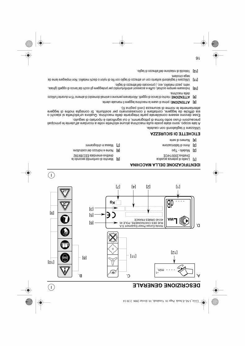
16
I
I
DESCRIZIONE GENERALE
IDENTIFICAZIONE DELLA MACCHINA
ETICHETTE DI SICUREZZAUtilizzare il tagliabordi con cautela.A tale scopo, sono state poste sulla macchina alcune etichette volte a ricordare all'utente le principaliprecauzioni d'uso sotto forma di pittogrammi, il cui significato è riportato di seguito.Esse devono essere considerate parte integrante della macchina. Qualora un'etichetta si stacchi osia difficile da leggere, contattare il concessionario per sostituirla. Si consiglia inoltre di leggereattentamente le norme di sicurezza (vedi pagina6).
[1]Livello di potenza acusticaDirettiva 2000/14/CE
[5]Marchio di conformità secondo ladirettiva emendata EEC/89/392
[2]Modello - Tipo[6]Nome e indirizzo del costruttore[3]Anno di fabbricazione[7]Massa in chilogrammi[4]Numero di serie
[8]ATTENZIONE: prima di usare la macchina leggere il manuale utente.[9]ATTENZIONE: rischio di lancio di oggetti. Allontanare persone o animali domestici di almeno 15 m durante l'utilizzo
della macchina.[10]Indossare sempre occhiali, cuffie e accessori antinfortunistici per proteggere gli occhi dal lancio di oggetti (ghiaia,
vetro, pezzi metallici, ecc..) provocato dall'attrezzo di taglio.[11]Utilizzare il tagliabordi soltanto con un attrezzo di taglio con filo di nylon o dischi metallici. Non impiegare lame da
sega circolare.[12]Velocità di rotazione dell'attrezzo di taglio.
[8] [11][12]
[10]
[9]
B. A.C.
D.
-1
[1]
[5]
[7]
[6]
[2][4]
[3]
HondaEuropePowerEquipmentS.A.RUEDESCHATAIGNIERS,POLE4545140ORMESFRANCE
Kg
WA
110dB
L
15m
Livre_I-NL-E.book Page 16 Vendredi, 10. février 2006 2:30 14

NL
EDESCRIPCIÓN GENERAL
BESCHRIJVINGKORTE KENNISMAKING
[1]Motor[A]Waarschuwing: Toerental snijgereedschap[2]Bougie[B]Waarschuwing: Algemene voorschriften[3]Trekstarter[C]Waarschuwing: Toegestane snijgereedschappen[4]Luchtfilter[D]Typeplaat[5]Benzinetank[6]Gaskabel[7]Koppeling[8]Handgreep[9]Gashandle
[10]Ontstekingsschakelaar (Aan/Uit)[11]Aandrijfas[12]Stenenschild[13]Transportkap[14]Transmissie[15]Nylontrimmerkop[16]Drietandsmes[17]Haakoog[18]Enkelbandsdraagstel[19]Dubbelbandsdraagstel[20]Dubbele handgreep[21]Enkele handgreep[22]Snoermes
15
IDENTIFICACIÓN DEL MATERIAL[1]Motor[A]Advertencia de seguridad: Velocidad de rotación[2]Bujíade la herramienta de corte[3]Asa de lanzador[B]Advertencia de seguridad: Instrucciones generales[4]Filtro de aire[C]Advertencia de seguridad: Herramientas de corte[5]Depósito de gasolinaautorizados[6]Cable de acelerador[D]Placa de datos[7]Cárter de embrague[8]Manija de mando[9]Gatillo de control de gases
[10]Interruptor Marcha/Parada[11]Arbol de transmisión[12]Protector de herramienta[13]Protector de transporte[14]Caja de transmisión[15]Cabezal de corte de hilo nylon[16]Disco 3 dientes[17]Punto de enganche del arnés[18]Arnés doble[19]Arnés confort[20]Manillar[21]Manija simple[22]Cuchilla corte hilo
Livre_I-NL-E.book Page 15 Vendredi, 10. février 2006 2:30 14

14
I
I
DESCRIZIONE GENERALE
IDENTIFICAZIONE DELL'ATTREZZATURA[1]Motore[A]Avvertenze relative alla sicurezza: velocità di[2]Candelarotazione dell'attrezzo di taglio[3]Manopola di avviamento a corda[B]Avvertenze relative alla sicurezza: norme generali[4]Filtro dell'aria[C]Avvertenze relative alla sicurezza: attrezzi da tagli[5]Serbatoio del carburanteautorizzati[6]Cavetto dell'acceleratore[D]Piastrina d'identificazione[7]Scatola della frizione[8]Manopola di comando[9]Leva di comando acceleratore
[10]Interruttore Avvio/Arresto[11]Albero di trasmissione[12]Protezione utensile[13]Protezione da trasporto[14]Scatola di trasmissione[15]Testa di taglio con filo di nylon[16]Lama a 3 denti[17]Punto di ancoraggio imbracatura[18]Imbracatura doppia[19]Imbracatura comfort[20]Manubrio[21]Manopola semplice[22]Lama tagliafilo
[18]
[19]
[4]
[20]
[8][14]
[1]
[7]
[3]
[5]
[1][6]
[10]
[16]
[9]
[D]
[B][C]
[A][13]
[22]
[11]
[A]
[D]
[15]
[12]
[21][17]
[10]
[9]
[8]
[2]
Livre_I-NL-E.book Page 14 Vendredi, 10. février 2006 2:30 14

NL
EINTRODUCCIÓN
INLEIDINGGeachte lezer,Wij danken u hartelijk voor de aankoop van deze Honda-bosmaaier. Deze handleiding is een volledige beschrijving van uw nieuwe machine met instructies voor gebruiken onderhoud.De techniek staat niet stil en Honda verbetert haar machines dan ook voortdurend. Honda kan zichhelaas niet verplichten, haar klanten van eventuele wijzigingen van te voren op de hoogte te stellenof aanvullende gegevens te publiceren.De illustraties in deze handleiding tonen het model dat het meest representatief is voor hetbehandelde onderwerp.In geval van moeilijkheden of vragen betreffende een machine dient u zich tot uw dealer te wenden.Deze handleiding dient beschouwd te worden als een integrerend deel van de bosmaaier. Wanneeru de machine inruilt of verkoopt, vergeet dan niet, de handleiding er bij te doen. De nieuwe eigenaarzal u dankbaar zijn.Wij verzoeken u, de garantievoorwaarden zorgvuldig te lezen opdat u volledig op de hoogte bent vanuw rechten en verantwoordelijkheden.Het garantiebewijs is een afzonderlijk document dat verstrekt is door uw dealer. Het is niettoegestaan, deze handleiding of delen daarvan zonder voorafgaande schriftelijke toestemming tekopiëren.
TOELICHTING BIJ DE IN DEZE HANDLEIDING GEBRUIKTE CODES(zie tabel blz12)
1ste uitgave: 10/2002
13
Señora, señor,Acaba de comprar una desbrozadora Honda y le agradecemos su confianza. Este manual se ha redactado para familiarizarlo con esta nueva máquina, permitiéndole utilizarla enlas mejores condiciones y mantenerla en buen estado.Deseosos de hacer que pueda aprovecharse de la mejor manera de las evoluciones tecnológicas,nuevos equipos o materiales y de nuestra experiencia, los modelos se han ido mejorandoregularmente. De ahí que las características y informaciones contenidos en este manual se puedanmodificar sin aviso previo y sin obligación a actualizarlo.Las ilustraciones de este manual muestran el modelo más representativo para el tema tratado.Si tiene un problema o cualquier pregunta en relación con la máquina, diríjase a su concesionario oa un revendedor homologado por Honda.Conserve este manual al alcance de la mano para consultarlo en cualquier momento y asegúresede que acompaña la máquina si se trata de una reventa. Le recomendamos lea el seguro de garantía para conocer todos sus derechos y responsabilidades.El seguro de garantía es un documento separado suministrado por su concesionario. Está prohibidohacer cualquier reproducción, incluso parcial, de la presente publicación, sin autorización escritaprevia.
EXPLICACIÓN DE LOS CÓDIGOS UTILIZADOS EN ESTE MANUAL(véase cuadro página12)
1a edición: 10/2002
Livre_I-NL-E.book Page 13 Vendredi, 10. février 2006 2:30 14

12
I
I
INTRODUZIONE
Gentile Cliente,La ringraziamo per la fiducia dimostrata acquistando un tagliabordi Honda.Il presente manuale è stato redatto affinché possa acquisire familiarità con la nuova macchina,utilizzarla al meglio ed effettuarne la manutenzione.Per consentirLe di apprezzare al massimo i progressi tecnologici, le nuove attrezzature e la nostraesperienza, i modelli sono stati sottoposti a miglioramenti costanti; ecco perché le caratteristiche ele informazioni contenute nel presente manuale sono soggetti a modifiche senza preavviso néobbligo di aggiornamento. Le illustrazioni qui contenute si riferiscono al modello più rappresentativo per l'argomento trattato.In caso di problemi o ulteriori chiarimenti relativi alla macchina, può rivolgersi al concessionario o aun rivenditore autorizzato Honda.Tenga il presente manuale a portata di mano per poterlo consultare in qualsiasi momento e si accertiche accompagni la macchina, qualora fosse rivenduta.Le raccomandiamo di leggere il certificato di garanzia per comprendere al meglio doveri eresponsabilità.Tale certificato è un documento separato fornito dal concessionario. Non sono ammesseriproduzioni, anche parziali, della presente pubblicazione, senza previa autorizzazione scritta.DESCRIZIONE DEI CODICI UTILIZZATI NEL MANUALE(vedi tabella pagina12)
1° edizione: 10/2002
Esempio / Voorbeeld / Ejemplo :UMK435E UE ET
ModelloModelModelo
UMK435E
TipiTypenTipos
UU =
L =
Modello a manubriodoppioModello a manubriosemplice
U =
L =
Model metdubbele handgreep Model metenkele handgreep
U =
L =
Modelo con manillardobleModelo conmanillar simple
EE =Con lama a 3 denti + Testa con filo di nylon
E =Met drietandsmes + Nylontrimmerkop
E =Con disco 3 dientes + Cabezal de hilo nilon
OpzionelOptie
Opciones
ETET =Modello europeoET =Europees modelET =Modelo europeo
INLE
Livre_I-NL-E.book Page 12 Vendredi, 10. février 2006 2:30 14

11
INSTRUCCIONES DE SEGURIDADB7.Cuide de que el ralentí esté correctamente ajustado para que la herramienta se detenga al soltar el gatillo de mando de los
gases.B8.Instale la pantalla de protección de la cuchilla en la herramienta de corte de cuchilla mientras se desmonta y se monta.
-Gire el conmutador de motor hacia la posición "STOP", y desmonte el capuchón de bujía de encendido.-Durante la operación, lleve guantes.
USOC1.No deje funcionar el motor en un lugar cerrado, en que los vapores tóxicos de monóxido de carbono puedan acumularse.C2.Trabaje únicamente con la luz del día.C3.Siempre que sea posible, evite utilizar la máquina en un terreno mojado.C4.Durante el trabajo, mantenga la distancia de seguridad respecto al cabezas de corte de hilo de nylon, proporcionada por la
posición del punto de enganche del arnés.C5.Ande, no corra ni se ponga en situación inestable. Tenga cuidado con los obstáculos como piedras, troncos etc. que podrían
hacerle tropezar.C6.Asegure sus pasos en las pendientes. Trabaje las pendientes en sentido transversal, nunca bajando o subiendo.C7.No utilice nunca la máquina en pendientes cuya inclinación presente un peligro para el usuario. Es responsabilidad del
usuario evaluar los riesgos potenciales del terreno a trabajar y tomar todas las decisiones necesarias para garantizar suseguridad. Esto es particularmente importante para las pendientes, los suelos accidentados, resbaladizos o tierrasmovedizas.
C8.No modifique nunca el reglaje del motor para ponerlo en sobretensión.C9.Antes de arrancar el motor, asegúrese de que ninguna persona se encuentra a menos de 15 metros de la maquina, que la
herramienta de corte no tocará el suelo y que la máquina está estable.C10.Arranque el motor con precaución, respetando las instrucciones de uso y quedándose alejado de la herramienta.C11.Pare el motor y desconecte el hilo de bujías en los siguientes casos:
-Antes de cualquier intervención en el sistema de corte-Antes de cualquier operación de limpieza, verificación, reglaje o reparación de la desbrozadora.-Los únicos reglajes que se realizan con el motor encendido son los del carburador y del ralentí.-Durante esta operación, procure evitar que la herramienta entre en contacto con cualquier objeto y que la máquina esté
en posición estable.-Al chocar con un objeto extraño, controle el sistema de corte y el árbol de transmisión verificando si están estropeados.
Efectúe las reparaciones necesarias antes de volver a utilizar la máquina.-Si la desbrozadora empieza a vibrar de manera anormal, busque inmediatamente las causa de estas vibraciones y
repárelas.C12.Pare el motor en los siguientes casos:
-Siempre que se deje sin vigilancia la desbrozadora-Antes de llenar con gasolina-Durante los desplazamientos entre zonas de trabajo.
C13.Riesgo de retroceso con todas las cuchillas rigidas.
MANTENIMIENTO Y ALMACENAMIENTOD1.Mantener todas las tuercas y tornillos apretados para garantizar condiciones seguras de uso. Un mantenimiento regular es
esencial para asegurar y conservar la calidad de rendimiento.D2.No utilice la máquina con piezas deterioradas o usadas. Las piezas se deben reemplazar y no reparar. Utilice piezas de
origen. Las herramientas de corte siempre deben llevar las marcas del fabricante y la referencia y la velocidad máxima deutilización. Piezas de calidad no equivalente pueden deteriorar la máquina y comprometer su seguridad.
D3.Lleve guantes gruesos para el desmontaje y el montaje del dispositivo de corte.D4.No guarde la desbrozadora con gasolina en el depósito en un local en que los vapores de gasolina podrían alcanzar una
llama, una chispa o una fuente importante de calor.D5.Guárdela en un local seco y limpio, fuera del alcance de los niños.D6.Deje que le motor se enfríe antes de guardar la máquina en un local cualquiera.D7.Para reducir los riesgos de incendio, saque todas las hojas, hierbas y aceite sobrante de la desbrozadora, en particular deje
limpio el motor, sus aletas de refrigeración, el tubo de escape y la zona de almacenamiento de la gasolina.D8.Al guardarla o al desplazarla, tape la cuchilla de corte con su funda protectora de transporte para evitar heridas por contacto
accidental.D9.Si debe vaciar el depósito de gasolina, efectúe esta operación fuera y con el motor frío.
D10.A efectos de respetar el medio ambiente, no se debe desechar el aceite gastado o la gasolina vertiéndolos a la alcantarilla,o a la calle o en el suelo. Una gasolinera local se encargará de que se recicle el aceite y la gasolina con toad seguridad.
E
Livre_I-NL-E.book Page 11 Vendredi, 10. février 2006 2:30 14

10
INSTRUCCIONES DE SEGURIDADCualquier pieza de la máquina puede representar una fuente potencial de peligro en caso de uso omantenimiento incorrecto. Conviene prestar mucha atención a las secciones precedidas de laspalabras siguientes.
Le advertimos que si no se cumplen las instrucciones, existe un riesgo de heridas corporalesgraves o de deterioro del material.
PRECAUCIÓN:•Le advertimos que si no se cumplen las instrucciones, existe un riesgo de heridas corporales
graves o de deterioro del material.
NOTA: Fuente de informaciones útiles.
Este signo le incita a ser prudente al realizar ciertas operaciones. Consulte lasinstrucciones de seguridad de las páginas siguientes, puntos indicados en lacasilla.
FORMACIÓN:A1.Lea atentamente las instrucciones de este manual. Familiarícese con el uso correcto y los mandos antes de utilizar el
desbrozadora. Sepa parar el motor rápidamente.A2.Utilice el desbrozadora para el uso a que está destinado, o sea:
-Cortar la hierba con un hilo de nylon, en los bordes de los macizos, plantaciones, muros, cercados o zonas verdes desuperficie reducida, para rematar el corte realizado con un cortacéspedes.
-Cualquier otra utilización puede resultar peligrosa o generar un deterioro de la máquina.A3.No permita nunca el uso de la máquina a niños o personas no familiarizadas con las instrucciones, el uso de la
desbrozadora. La regulación local puede exigir una edad límite para el usuario.A4.No se utilice la desbrozadora:
-Cuando estén personas y particularmente niños o animales a proximidad. Respete la distancia de seguridad de 15 metrosmínimo entre la máquina y las personas eventualmente presentes. Solo una persona debe manejar la desbrozadora.
-Si el usuario ha tomado medicamentos o sustancias conocidas por reducir su capacidad de reflejos y vigilancia.-En caso de utilizar un cabezal con hilo de nylon, asegúrese de que la extensión del protector y la cuchilla cortahilo están
bien colocadas, a efectos de que el hilo quede cortado en el largo correcto.-Si no hay dispositivos de seguridad como el protector de herramienta o si el protector está deteriorado.
A5.No modifique su desbrozadora. Esto podría poner en peligro su seguridad exponiéndole a accidentes o heridas graves.A6.Recuerde que los accidentes o los riesgos a que se exponen terceros y sus pertenencias son responsabilidad del usuario
o propietario.PREPARACION
B1.No utilice el material si está descalzo o si lleva sandalias y prendas amplias que se podrían enganchar en la maleza.Duranteel trabajo, es obligatorio llevar pantalones largos, botas o zapatos de seguridad con suelas antideslizantes, gafas o visor deprotección contra las proyecciones, guantes, preferentemente de cuero y un casco antirruido.En zonas en que pueden caerobjetos (ramas, piedras...), protéjase la cabeza con un casco de seguridad.
B2.Observe en detalle la zona a desbrozar y elimine todos los objetos extraños que la máquina podría proyectar ( piedras,trozos de madera, alambres, huesos, etc.).
B3.¡ATENCION: PELIGRO! La gasolina es muy inflamable.Conserve la gasolina en recipientes especialmente previstos para eso.-Efectúe el llenado únicamente fuera, antes de arrancar el motor y no fume durante esta operación o cualquier
manipulación de gasolina.-No saque el tapón del depósito de gasolina ni efectúe el llenado mientras esté funcionando el motor o está todavía
caliente.-No arranque el motor si se ha derramado gasolina: aleje la desbrozadora de la zona en que se ha vertido la gasolina y
no provoque ninguna inflamación mientras la gasolina no se haya evaporado y que los vapores no se hayan disipado.-Cierre correctamente el depósito y el recipiente, apretando correctamente los tapones.
B4.Reemplace los silenciadores de escape defectuosos.B5.Antes de cada utilización, proceda siempre a una verificación general y en particular el aspecto de las herramientas,
conjunto de corte, tapas de protección y tapones de fijación, para asegurarse de que no están desgastados ni deterioradoso aflojados. Verifique siempre que los gatillos de control de gases y el botón de parada "STOP" funcionan correctamente.
B6.Cuide de que las manijas y el punto de enganche del arnés estén correctamente posicionados, y que la máquina esté bienequilibrada. Las posiciones y reglajes correctos se explican en el capítulo "Preparación y verificación antes del uso" de estemanual.
E
SEGURIDAD
Livre_I-NL-E.book Page 10 Vendredi, 10. février 2006 2:30 14

9
VEILIGHEIDSVOORSCHRIFTENB7.Kijk of de toerenknop goed is ingesteld: het loslaten van de gastrekker moet de machine tot stilstand brengen.B8.Breng de transportkap aan op het snijgereedschap wanneer u dit demonteert of monteert.
-Druk de STOP-schakelaar in de stand STOP en neem de kap van de bougie.-Draag bij deze werkzaamheden stevige handschoenen.
GEBRUIKC1.Uitlaatgas bevat koolmonoxide, een giftig gas. Start de machine dus alleen binnen wanneer het lokaal goed geventileerd is. C2.Werk uitsluitend bij daglicht.C3.Werk zo min mogelijk op nat terrein.C4.Blijf tijdens het werk op veilige afstand van de nylontrimmerkop. Deze is aangegeven door het oog van het draagstel.C5.Loop altijd rustig en langzaam. Blijf te allen tijde in evenwicht. Houd u voor obstakels als stenen, stronken e.d. waar u over
zou kunnen struikelen.C6.Kijk bij het werken op een helling waar u loopt. Maai altijd dwars op de helling, nooit van boven naar beneden of van beneden
naar boven.C7.Gebruik de bosmaaier nooit op gevaarlijke hellingen. De gebruiker is zelf aansprakelijk voor het beoordelen van de risico's
van het terrein alsook voor het nemen van de geëigende voorzorgsmaatregelen. Dit geldt met name voor steile hellingen,geaccidenteerd terrein en glibberige of losse grond.
C8.De machine mag in geen geval worden opgevoerd of met te hoog toerental worden gebruikt.C9.Overtuig u ervan dat eventuele omstanders zich op een veilige afstand van tenminste 15 meter bevinden, dat het
snijgereedschap de grond of obstakels niet kan raken en dat de bosmaaier stevig op de grond is geplaatst wanneer u hemstart.
C10.Start de motor met inachtneming van de veilige afstand tussen u en het snijgereedschap.C11.In de onderstaande gevallen moet de motor worden uitgeschakeld en de kap van de bougie worden genomen:
-Voor u enigerlei werkzaamheden aan het snijgereedschap uitvoert.-Voor u de machine reinigt, inspecteert, nastelt of repareert.-Alleen voor nastellen van de carburateur en het stationair toerental mag de motor draaien.-Vergewis u er bij het nastellen van dat de bosmaaier stevig op de grond is geplaatst en dat het draaiende snijgereedschap
niets kan raken.-Nadat het snijgereedschap een hard voorwerp heeft geraakt. Inspecteer het snijgereedschap en de transmissie-as
terstond op schade en voer de nodige reparaties uit voor u de machine opnieuw start en gebruikt.-Bij abnormaal trillen van de machine: spoor de oorzaak onmiddellijk op en elimineer deze.
C12.Schakel in de onderstaande gevallen de motor uit:-Wanneer u de machine zonder toezicht achter moet laten,-Voor u de machine met benzine navult,-Wanneer u de bosmaaier van het ene terrein naar het andere draagt.
C13."Kickout" risico bij het gebruik van een zaagblad op uw bosmaaier.
ONDERHOUD EN WINTERBERGINGD1.Voor een veilig gebruik van de machine moeten bouten moeren te allen tijd stevig vastzitten. Regelmatig onderhoud is van
wezenlijk belang voor uw veiligheid en het handhaven van de prestaties van de machine.D2.Gebruik de bosmaaier niet met beschadigde of versleten onderdelen. Onderdelen moeten worden vervangen en kunnen
niet worden gerepareerd. Gebruik uitsluitend originele onderdelen. Snijgereedschap moet het merk van de fabrikant dragenalsook het onderdeelnummer en het maximale toerental. Merkvreemde onderdelen kunnen de machine beschadigen en uwpersoonlijke veiligheid in gevaar brengen.
D3.Draag stevige werkhandschoenen bij het monteren en demonteren van het snijgereedschap.D4.Berg de bosmaaier nooit op met benzine in de tank om te voorkomen dat benzinedampen tot ontbranding kunnen komen
(vonken, open vuur of hete voorwerpen).D5.Berg de machine op in een schone, droge ruimte waar kinderen er niet bijkunnen.D6.Laat de motor afkoelen voor u de machine in een afgesloten ruimte opbergt.D7.U kunt het risico van brand verregaand beperken door de machine te reinigen van bladeren, gras en olie. Besteed hierbij
vooral aandacht aan de koelribben en de uitlaat. Controleer tevens de plaats waar u benzineblikken of Jerrycans opslaat opbrandgevaar.Voorkom brand; houd de machine en de plaats waar u volle jerrycans opbergt schoon (verwijder gras, bladerenen overtollig vet).
D8.Monteer de plastic kap op het snijgereedschap wanneer de bosmaaier wordt weggeborgen of vervoerd.D9.Ledig de benzinetank altijd buiten, en met koude motor.
D10.Benzine en afgewerkte olie mogen in geen geval in het riool, de goot of op de grond worden gestort. Lever de benzine ende olie in bij een benzinestation, waar het volgens de voorschriften wordt afgevoerd.
NL
Livre_I-NL-E.book Page 9 Vendredi, 10. février 2006 2:30 14

8
VEILIGHEIDSVOORSCHRIFTENElk onderdeel van de machine kan bij verkeerd gebruik of gebrekkig onderhoud en potentieel gevaarzijn. Lees daarom rubrieken voorafgegaan door.
Veronachtzamen van deze instructie kan tot ernstig en zelfs dodelijk letsel aanleiding geven.
VORSICHT:•Veronachtzamen van deze instructie kan letsel en schade aan de bosmaaier veroorzaken.
NB: Aanvullende inlichtingen.
Dit symbool maant u tot voorzichtigheid bij het uitvoeren van bepaaldewerkzaamheden. Zie de veiligheidsvoorschriften in de volgende bladzijden op dein het vierkant aangeduide punten.
VORMINGA1.Lees deze handleiding aandachtig. Maak u vertrouwd met bediening en gebruik van de bosmaaier. U moet te allen tijde de
motor onmiddellijk kunnen uitschakelen.A2.Gebruik de bosmaaier alleen voor het doel waarvoor hij ontworpen is, d.w.z.:
-Het met de nylondraad verwijderen van gras aan de rand van borders, beplantingen, aan de voet van muren, afrasteringenof kleine gazons na het gebruik van een gazonmaaier.
-Alle andere toepassingen vallen onder het begrip oneigenlijk gebruik.A3.Indien kinderen de bosmaaier willen gebruiken, moeten ook zij deze handleiding hebben gelezen en met het gebruik van de
machine vertrouwd zijn. In bepaalde landen is het werken met tuinmachines onder een bepaalde leeftijd verboden.A4.Gebruik de bosmaaier niet:
-Wanneer personen en in het bijzonder kinderen of dieren zich in de buurt bevinden. Houd iedereen op een veilige afstandvan tenminste 15 m. De bosmaaier mag door slechts één persoon tegelijk gebruikt worden.
-Wanneer u medicijnen of andere middelen gebruikt waarvan bekend is dat deze de reflexen en de waakzaamheid nadeligbeïnvloeden.
-Controleer bij gebruik van een nylontrimmerkop of het stenenschild en het snoermes gemonteerd zijn, anders kan hetsnoer niet automatisch op de juiste lengte worden afgekort.
-Wanneer de beveiligingen als de gereedschapsbeschermer niet gemonteerd of beschadigd is.A5.Breng aan uw bosmaaier geen wijzigingen aan. Dit kan uw persoonlijke veiligheid in ernstig gevaar brengen en uw
blootstellen aan ongevallen en ernstig lichamelijk letsel.A6.Bedenk dat de eigenaar of gebruiker aansprakelijk is voor letsel en schade aan derden.
VOORBEREIDINGENB1.Gebruik de bosmaaier niet blootsvoets of wanneer u sandalen en losse kleding draagt dat in het struikgewas vast kan
raken.Tijdens het gebruik van de bosmaaier moeten een lange broek, laarzen of werkschoenen met antislipzolen, eenveiligheidsbril of een gelaatscherm als bescherming tegen weggeslingerde voorwerpen, werkhandschoenen (bij voorkeurvan leer) en een gehoorbeschermer worden gedragen.Draag een veiligheidshelm als het werk gevaar van hoofdverwondingdoor takken of vallende voorwerpen met zich brengt.
B2.Inspecteer het terrein zorgvuldig en verwijder alle voorwerpen die door de machine weggeslingerd kunnen worden (stenen,stukken hout, stukken ijzerdraad, botten e.d.).
B3.OPGEPAST: GEVAAR! Benzine is uiterst brandgevaarlijk.Bewaar benzine in de geëigende Jerrycans.-Vul de machine uitsluitend na in de buitenlucht en bij uitgeschakelde motor. Niet roken tijdens het navullen.-Neem nooit de dop van de benzinetank bij draaiende of hete motor.-Bij gemorste benzine: Machine niet starten en zolang elders neerleggen. Niet roken, geen vuur maken. Wacht tot alle
benzine verdampt is.-Draai de dop na vullen stevig op de benzinetank én de Jerrycan.
B4.Vervang de uitlaatgeluiddemper wanneer deze defect is.B5.Controleer de bosmaaier altijd voorafgaande aan het gebruik; controleer met name het snijgereedschap, de beplating en
bevestigingsbouten en -moeren om u er van te vergewissen dat deze noch versleten, noch beschadigd, noch losgetrild zijn.Controleer altijd de goede werking van de gashandle en de STOP-knop.
B6.Controleer of de handgrepen en de draagstel-oog zich in de juiste stand bevinden en of de machine goed uitgebalanceerdis. De stand van de handgrepen en de draagstel-oog zijn toegelicht in het hoofdstuk "Voorbereidingen en controlesvoorafgaande aan het gebruik".
NL
VEILIGHEID
Livre_I-NL-E.book Page 8 Vendredi, 10. février 2006 2:30 14

7
NORME DI SICUREZZAB7.Controllare la corretta regolazione del minimo in modo che la rotazione dell'attrezza sia interrotta appena si rilascia la leva
dell'acceleratore.B8.Posizionare il coprilama sull'attrezzo di taglio a lama durante la rimozione e l'immagazzinaggio.
-Ruotare il commutatore di motore in posizione STOP e rimuovere il cappuccio della candela di accensione.-Durante l'operazione, indossare i guanti.
UTILIZZOC1.Non avviare il motore in un ambiente ristretto dove potrebbero accumularsi i vapori tossici di monossido di carbonio.C2.Operare esclusivamente alla luce del giorno.C3.Per quanto possibile, evitare l'impiego della macchina su terreno umido.C4.Durante il lavoro, mantenere la distanza di sicurezza dalla testa di taglio con filo di nylon, indicata dalla posizione del punto
di ancoraggio dell'imbracatura.C5.Camminare, non correre né porsi in situazioni di equilibrio instabile. Diffidare degli ostacoli, come pietre, cappi, ecc., che
potrebbero fare inciampare. C6.Sui pendii, assestare bene i passi e operare in senso trasversale, non in salita o in discesa.C7.Non utilizzare la macchina su pendii la cui inclinazione risulti pericolosa per l'utente, che è responsabile della valutazione
dei potenziali rischi presentati dal terreno su cui opera e dell'adozione delle precauzioni necessarie ad agire in sicurezza.Ciò è particolarmente importante su pendii, terreni accidentati, scivolosi o friabili.
C8.Non modificare la regolazione del motore per raggiungere una velocità eccessiva.C9.Prima di avviare il motore, verificare che nessuno si trovi a meno di 15 metri dalla macchina, che l'attrezzo di taglio non
tocchi il suolo e che la macchina sia stabile.C10.Avviare il motore con cautela, rispettando le istruzioni per l'uso e stando lontani dall'attrezzo.C11.Arrestare il motore e staccare il filo della candela nei seguenti casi:
-Prima di intervenire sul sistema di taglio.-Prima di effettuare operazioni di pulizia, verifica, regolazione o riparazione del tagliabordi.-Soltanto le regolazioni del carburatore e del minimo sono eseguibili a motore acceso.-Durante tale operazione, accertare che l'attrezzo non sia a contatto con alcun oggetto e che la macchina sia in posizione
stabile.-In caso di urto con un corpo estraneo, controllare il sistema di taglio e l'albero di trasmissione per accertare eventuali
danni. Prima di utilizzare nuovamente la macchina, eseguire le riparazioni necessarie.-Se il tagliabordi inizia a vibrare in modo anomalo, accertare immediatamente la causa delle vibrazioni e risolvere il
problema.C12.Arrestare il motore nei seguenti casi:
-Ogni volta che il tagliabordi è lasciato incustodito.-Prima di procedere al rifornimento di carburante.-In caso di spostamento tra zone di lavoro.
C13.Rischio di disinnesto (contraccolpo della lama) con tutte le lame rigide.
MANUTENZIONE E STOCCAGGIOD1.Mantenere il serraggio di viti e bulloni per garantire condizioni di utilizzo in sicurezza. È essenziale eseguire una
manutenzione regolare per la sicurezza e il mantenimento del livello delle prestazioni.D2.Non utilizzare la macchina con pezzi danneggiati o usurati, che devono essere sostituiti, non riparati. Utilizzare pezzi
originali. Gli attrezzi di taglio devono sempre recare il marchio del produttore, nonché il riferimento e la velocità massimad'uso. L'impiego di pezzi di qualità non equivalente può provocare danni alla macchina e compromettere la sicurezza.
D3.Indossare guanti spessi per smontare e rimontare il dispositivo di taglio.D4.Non depositare il tagliabordi con il carburante nel serbatoio in un locale in cui i vapori di benzina potrebbero raggiungere
fiamme, scintille o fonti di calore elevato.D5.Riporre in un locale pulito e asciutto, lontano dalla portata dei bambini.D6.Lasciare raffreddare il motore prima di riporre la macchina in un qualsiasi locale.D7.Per ridurre il rischio di incendio, rimuovere dal tagliabordi foglie, fili d'erba e olio in eccesso, in particolare da motore, alette
di raffreddamento, marmitta di scappamento, nonché dalla zona di stoccaggio carburante.D8.Per il deposito o il trasporto, coprire sempre la lama da taglio con la relativa protezione da trasporto onde evitare lesioni
dovute a contatto accidentale.D9.Eseguire l'operazione di svuotamento del serbatoio del carburante all'esterno e a motore freddo.
D10.Nell'interesse del rispetto dell'ambiente, non eliminare olio usato o benzina tramite smaltimento in scarichi o conduttureoppure versamento sul terreno. Rivolgersi a una stazione di servizio in loco per provvedere al riciclo dell'olio e della benzinain tutta sicurezza.
I
Livre_I-NL-E.book Page 7 Vendredi, 10. février 2006 2:30 14

6
NORME DI SICUREZZAQualsiasi pezzo della machina può costituire una potenziale fonte di pericolo in caso di uso improprioo manutenzione scorretta. Si consiglia di prestare molta attenzione alle voci precedute dai termini diseguito riportati.
Rischi di lesioni fisiche gravi o morte, in caso di inadempienza alle istruzioni.PRECAUZIONI:•Possibili rischi di lesioni fisiche o danni materiali in caso di inadempienza alle istruzioni.
NOTA: Fonte di informazioni utili.
Questo segnale costituisce un richiamo alla prudenza durante lo svolgimento dideterminate operazioni. Fare riferimento alle norme di sicurezza nelle pagineseguenti, al(i) punto(i) indicato(i) nel riquadro.
FORMAZIONEA1.Leggere attentamente le istruzioni contenute nel presente manuale e acquisire familiarità con l'utilizzo corretto e i comandi
prima di utilizzare il tagliabordi. Apprendere ad arrestare rapidamente il motore.A2.Utilizzare il tagliabordi per lo scopo a cui è destinato, cioè:
-Taglio d'erba con filo di nylon sul bordo di cespugli, piantagioni, muri, recinzioni o spazi verdi di piccole dimensioni, rifinitotramite tosatura effettuata con tosaerba.
-Qualsiasi altro impiego può rivelarsi pericoloso o provocare un deterioramento della macchina.A3.Impedire l'utilizzo del tagliabordi a bambini o persone non aventi familiarità con le istruzioni per l'uso dello stesso. È possibile
che la normativa locale fissi un limite di età per l'utente.A4.Non utilizzare il tagliabordi :
-Con persone, soprattutto bambini, o animali nelle vicinanze. Rispettare la distanza di sicurezza minima pari a 15 metri trala macchina e le persone eventualmente presenti. Il tagliabordi deve essere manipolato da una persona sola.
-Se l'utente ha assunto farmaci o sostanze che si ritiene possano nuocere alla capacità di reazione e attenzione.-In caso di utilizzo di testa di taglio con filo di nylon, accertare che la prolunga di protezione e la lama tagliafilo siano
posizionate correttamente affinché la lunghezza del filo sia adeguata.-In assenza di dispositivi di sicurezza, come la protezione dell'utensile o in caso di danni alla protezione.
A5.Non modificare il tagliabordi, in quanto si rischia di compromettere seriamente la sicurezza esponendosi a incidenti o lesionigravi.
A6.Non dimenticare che il proprietario o l'utente è responsabile di incidenti o rischi in cui possano incorrere terzi e i beni di loroproprietà.
PREPARAZIONEB1.Non utilizzare l'attrezzatura a piedi nudi o indossando sandali e abiti ampi che potrebbero restare impigliati nei
cespugli.Durante il lavoro, è obbligatorio indossare pantaloni lunghi, stivali o calzature antinfortunistiche con suoleantisdrucciolo, occhiali o visiera di protezione dal lancio di oggetti, guanti preferibilmente in pelle, nonché cuffieantirumore.Nelle aree a rischio di caduta di oggetti (rami, pietre, ecc.) riparare la testa con un caschetto di sicurezza.
B2.Ispezionare accuratamente la zona da decespugliare ed eliminare eventuali oggetti estranei che potrebbero essere scagliatidalla macchina. (pietre, pezzi di legno, filo di ferro, ossa, ecc....).
B3.ATTENZIONE: PERICOLO! La benzina è altamente infiammabile.Conservare il carburante in appositi recipienti.-Fare il pieno all'esterno, soltanto prima di avviare il motore, evitando di fumare durante tale operazione o manipolando il
carburante.-Non rimuovere il tappo del serbatoio del carburante né fare il pieno quando il motore è in funzione o ancora caldo.-Non avviare il motore se è stata versata della benzina: allontanare il tagliabordi dalla zona in cui si è rovesciato il
carburante ed evitare fiamme fino all'evaporazione del carburante e la dissoluzione dei vapori.-Richiudere correttamente il serbatoio e il recipiente serrando adeguatamente i tappi.
B4.Sostituire i silenziatori di scarico difettosi.B5.Prima dell'uso, effettuare sempre una verifica generale, soprattutto dell'aspetto degli attrezzi, del gruppo di taglio, dei
rivestimenti protettivi e dei bulloni di fissaggio per accertare che non siano usurati, danneggiato o allentati. Verificare sempreil corretto funzionamento della leva di comando acceleratore e del pulsante di arresto "STOP''.
B6.Controllare il corretto posizionamento delle manopole e del punto di ancoraggio imbracatura, nonché il correttobilanciamento della macchina. Le posizioni e le regolazioni corrette sono descritte al capitolo "Preparazione e verifichepreliminari" nel presente manuale.
I
SICUREZZA
Livre_I-NL-E.book Page 6 Vendredi, 10. février 2006 2:30 14

5
NOTA / NB / NOTA . . . . . . . . . . . . . . . . . . . . . . . . . . . . . . . . . . . . . . . . . . . . . . . . . . . . . . . . . . . . . . . . . . . . . . . . . . . . . . . . . . . . . . . . . . . . . . . . . . . . . . . . . . . . . . . . . . . . . . . . . . . . . . . . . . . . . . . . . . . . . . . . . . . . . . . . . . . . . . . . . . . . . . . . . . . . . . . . . . . . . . . . . . . . . . . . . . . . . . . . . . . . . . . . . . . . . . . . . . . . . . . . . . . . . . . . . . . . . . . . . . . . . . . . . . . . . . . . . . . . . . . . . . . . . . . . . . . . . . . . . . . . . . . . . . . . . . . . . . . . . . . . . . . . . . . . . . . . . . . . . . . . . . . . . . . . . . . . . . . . . . . . . . . . . . . . . . . . . . . . . . . . . . . . . . . . . . . . . . . . . . . . . . . . . . . . . . . . . . . . . . . . . . . . . . . . . . . . . . . . . . . . . . . . . . . . . . . . . . . . . . . . . . . . . . . . . . . . . . . . . . . . . . . . . . . . . . . . . . . . . . . . . . . . . . . . . . . . . . . . . . . . . . . . . . . . . . . . . . . . . . . . . . . . . . . . . . . . . . . . . . . . . . . . . . . . . . . . . . . . . . . . . . . . . . . . . . . . . . . . . . . . . . . . . . . . . . . . . . . . . . . . . . . . . . . . . . . . . . . . . . . . . . . . . . . . . . . . . . . . . . . . . . . . . . . . . . . . . . . . . . . . . . . . . . . . . . . . . . . . . . . . . . . . . . . . . . . . . . . . . . . . . . . . . . . . . . . . . . . . . . . . . . . . . . . . . . . . . . . . . . . . . . . . . . . . . . . . . . . . . . . . . . . . . . . . . . . . . . . . . . . . . . . . . . . . . . . . . . . . . . . . . . . . . . . . . . . . . . . . . . . . . . . . . . . . . . . . . . . . . . . . . . . . . . . . . . . . . . . . . . . . . . . . . . . . . . . . . . . . . . . . . . . . . . . . . . . . . . . . . . . . . . . . . . . . . . . . . . . . . . . . . . . . . . . . . . . . . . . . . . . . . . . . . . . . . . . . . . . . . . . . . . . . . . . . . . . . . . . . . . . . . . . . . . . . . . . . . . . . . . . . . . . . . . . . . . . . . . . . . . . . . . . . . . . . . . . . . . . . . . . . . . . . . . . . . . . . . . . . . . . . . . . . . . . . . . . . . . . . . . . . . . . . . . . . . . . . . . . . . . . . . . . . . . . . . . . . . . . . . . . . . . . . . . . . . . . . . . . . . . . . . . . . . . . . . . . . . . . . . . . . . . . . . . . . . . . . . . . . . . . . . . . . . . . . . . . . . . . . . . . . . . . . . . . . . . . . . . . . . . . . . . . . . . . . . . . . . . . . . . . . . . . . . . . . . . . . . . . . . . . . . . . . . . . . . . . . . . . . . . . . . . . . . . . . . . . . . . . . . . . . . . . . . . . . . . . . . . . . . . . . . . . . . . . . . . . . . . . . . . . . . . . . . . . . . . . . . . . . . . . . . . . . . . . . . . . . . . . . . . . . . . . . . . . . . . . . . . . . . . . . . . . . . . . . . . . . . . . . . . . . . . . . . . . . . . . . . . . . . . . . . . . . . . . . . . . . . . . . . . . . . . . . . . . . . . . . . . . . . . . . . . . . . . . . . . . . . . . . . . . . . . . . . . . . . . . . . . . . . . . . . . . . . . . . . . . . . . . . . . . . . . . . . . . . . . . . . . . . . . . . . . . . . . . . . . . . . . . . . . . . . . . . . . . . . . . . . . . . . . . . . . . . . . . . . . . . . . . . . . . . . . . . . . . . . . . . . . . . . . . . . . . . . . . . . . . . . . . . . . . . . . . . . . . . . . . . . . . . . . . . . . . . . . . . . . . . . . . . . . . . . . . . . . . . . . . . . . . . . . . . . . . . . . . . . . . . . . . . . . . . . . . . . . . . . . . . . . . . . . . . . . . . . . . . . . . . . . . . . . . . . . . . . . . . . . . . . . . . . . . . . . . . . . . . . . . . . . . . . . . . . . . . . . . . . . . . . . . . . . . . . . . . . . . . . . . . . . . . . . . . . . . . . . . . . . . . . . . . . . . . . . . . . . . . . . . . . . . . . . . . . . . . . . . . . . . . . . . . . . . . . . . . . . . . . . . . . . . . . . . . . . . . . . . . . . . . . . . . . . . . . . . . . . . . . . . . . . . . . . . . . . . . . . . . . . . . . .
INLE
Livre_I-NL-E.book Page 5 Vendredi, 10. février 2006 2:30 14

4
E INDICENOTA . . . . . . . . . . . . . . . . . . . . . . . . . . . . . . . . . . . . . . . . . . . . . . . . . . . . . . . . . . . . . . . . . . . . . . . .5
INSTRUCCIONES DE SEGURIDAD . . . . . . . . . . . . . . . . . . . . . . . . . . . . . . . . . . . . . . . . . . . . . . 10
INTRODUCCIÓN . . . . . . . . . . . . . . . . . . . . . . . . . . . . . . . . . . . . . . . . . . . . . . . . . . . . . . . . . . . . . .13Explicación de los códigos utilizados en este manual . . . . . . . . . . . . . . . . . . . . . . . . . . . . . . . . . .13
DESCRIPCIÓN GENERAL. . . . . . . . . . . . . . . . . . . . . . . . . . . . . . . . . . . . . . . . . . . . . . . . . . . . . . .15Identificación del material . . . . . . . . . . . . . . . . . . . . . . . . . . . . . . . . . . . . . . . . . . . . . . . . . . . . . . . .15IDentificacion de la maquina. . . . . . . . . . . . . . . . . . . . . . . . . . . . . . . . . . . . . . . . . . . . . . . . . . . . . .17Etiquetas de seguridad. . . . . . . . . . . . . . . . . . . . . . . . . . . . . . . . . . . . . . . . . . . . . . . . . . . . . . . . . .17
MONTAJE. . . . . . . . . . . . . . . . . . . . . . . . . . . . . . . . . . . . . . . . . . . . . . . . . . . . . . . . . . . . . . . . . . . .19Manijas y manillar. . . . . . . . . . . . . . . . . . . . . . . . . . . . . . . . . . . . . . . . . . . . . . . . . . . . . . . . . . . . . .19Proteccion completa . . . . . . . . . . . . . . . . . . . . . . . . . . . . . . . . . . . . . . . . . . . . . . . . . . . . . . . . . . . .21Ensamble de los sistemas de corte . . . . . . . . . . . . . . . . . . . . . . . . . . . . . . . . . . . . . . . . . . . . . . . .21Montaje y reglaje del arnes. . . . . . . . . . . . . . . . . . . . . . . . . . . . . . . . . . . . . . . . . . . . . . . . . . . . . . .25
PREPARACIÓN Y VERIFICACIONES ANTES DEL USO . . . . . . . . . . . . . . . . . . . . . . . . . . . . . .27Equilibrado de la máquina. . . . . . . . . . . . . . . . . . . . . . . . . . . . . . . . . . . . . . . . . . . . . . . . . . . . . . . .27Llenado del deposito de carburante . . . . . . . . . . . . . . . . . . . . . . . . . . . . . . . . . . . . . . . . . . . . . . . .29Llenado del deposito de aceite. . . . . . . . . . . . . . . . . . . . . . . . . . . . . . . . . . . . . . . . . . . . . . . . . . . .31Control del nivel de aceite. . . . . . . . . . . . . . . . . . . . . . . . . . . . . . . . . . . . . . . . . . . . . . . . . . . . . . . .31Antes de poner en marcha . . . . . . . . . . . . . . . . . . . . . . . . . . . . . . . . . . . . . . . . . . . . . . . . . . . . . . .31
PUESTA EN MARCHA Y PARADA DEL MOTOR . . . . . . . . . . . . . . . . . . . . . . . . . . . . . . . . . . . .33Arranque en frio . . . . . . . . . . . . . . . . . . . . . . . . . . . . . . . . . . . . . . . . . . . . . . . . . . . . . . . . . . . . . . .33ARranque en caliente . . . . . . . . . . . . . . . . . . . . . . . . . . . . . . . . . . . . . . . . . . . . . . . . . . . . . . . . . . .35Parada del motor. . . . . . . . . . . . . . . . . . . . . . . . . . . . . . . . . . . . . . . . . . . . . . . . . . . . . . . . . . . . . . .35
USO . . . . . . . . . . . . . . . . . . . . . . . . . . . . . . . . . . . . . . . . . . . . . . . . . . . . . . . . . . . . . . . . . . . . . . . .37
MANTENIMIENTO . . . . . . . . . . . . . . . . . . . . . . . . . . . . . . . . . . . . . . . . . . . . . . . . . . . . . . . . . . . . .49Reglaje del carburador . . . . . . . . . . . . . . . . . . . . . . . . . . . . . . . . . . . . . . . . . . . . . . . . . . . . . . . . . .49Verificación de la bujía de encendido. . . . . . . . . . . . . . . . . . . . . . . . . . . . . . . . . . . . . . . . . . . . . . .49Cambio de aceite del motore . . . . . . . . . . . . . . . . . . . . . . . . . . . . . . . . . . . . . . . . . . . . . . . . . . . . .51Mantenimiento del filtro de aire. . . . . . . . . . . . . . . . . . . . . . . . . . . . . . . . . . . . . . . . . . . . . . . . . . . .51Engrase de la caja de transmisión . . . . . . . . . . . . . . . . . . . . . . . . . . . . . . . . . . . . . . . . . . . . . . . . .51Calendario de mantenimiento. . . . . . . . . . . . . . . . . . . . . . . . . . . . . . . . . . . . . . . . . . . . . . . . . . . . .54
DETECCIÓN DE AVERÍAS . . . . . . . . . . . . . . . . . . . . . . . . . . . . . . . . . . . . . . . . . . . . . . . . . . . . . 57
TRANSPORTAR Y GUARDAR . . . . . . . . . . . . . . . . . . . . . . . . . . . . . . . . . . . . . . . . . . . . . . . . . . .59Transportar . . . . . . . . . . . . . . . . . . . . . . . . . . . . . . . . . . . . . . . . . . . . . . . . . . . . . . . . . . . . . . . . . . .59Guardar. . . . . . . . . . . . . . . . . . . . . . . . . . . . . . . . . . . . . . . . . . . . . . . . . . . . . . . . . . . . . . . . . . . . . .59
ACCESORIOS . . . . . . . . . . . . . . . . . . . . . . . . . . . . . . . . . . . . . . . . . . . . . . . . . . . . . . . . . . . . . . . .61
ESPECIFICACIONES TÉCNICAS. . . . . . . . . . . . . . . . . . . . . . . . . . . . . . . . . . . . . . . . . . . . . . . . 64
Livre_I-NL-E.book Page 4 Vendredi, 10. février 2006 2:30 14

3
NLINHOUDNB. . . . . . . . . . . . . . . . . . . . . . . . . . . . . . . . . . . . . . . . . . . . . . . . . . . . . . . . . . . . . . . . . . . . . . . . . . .5
VEILIGHEIDSVOORSCHRIFTEN. . . . . . . . . . . . . . . . . . . . . . . . . . . . . . . . . . . . . . . . . . . . . . . . . . .8
INLEIDING . . . . . . . . . . . . . . . . . . . . . . . . . . . . . . . . . . . . . . . . . . . . . . . . . . . . . . . . . . . . . . . . . . .13Toelichting bij de in deze handleiding gebruikte codes. . . . . . . . . . . . . . . . . . . . . . . . . . . . . . . . . .13
BESCHRIJVING . . . . . . . . . . . . . . . . . . . . . . . . . . . . . . . . . . . . . . . . . . . . . . . . . . . . . . . . . . . . . . .15Korte kennismaking. . . . . . . . . . . . . . . . . . . . . . . . . . . . . . . . . . . . . . . . . . . . . . . . . . . . . . . . . . . . .15Typeplaat. . . . . . . . . . . . . . . . . . . . . . . . . . . . . . . . . . . . . . . . . . . . . . . . . . . . . . . . . . . . . . . . . . . . .17Waarschuwingsstickers. . . . . . . . . . . . . . . . . . . . . . . . . . . . . . . . . . . . . . . . . . . . . . . . . . . . . . . . . .17
MONTAGE . . . . . . . . . . . . . . . . . . . . . . . . . . . . . . . . . . . . . . . . . . . . . . . . . . . . . . . . . . . . . . . . . . .19Handgrepen. . . . . . . . . . . . . . . . . . . . . . . . . . . . . . . . . . . . . . . . . . . . . . . . . . . . . . . . . . . . . . . . . . .19Bodemkap/afstandstuk . . . . . . . . . . . . . . . . . . . . . . . . . . . . . . . . . . . . . . . . . . . . . . . . . . . . . . . . . .21Snijgereedschap monteren . . . . . . . . . . . . . . . . . . . . . . . . . . . . . . . . . . . . . . . . . . . . . . . . . . . . . . .21Draagstel monteren en pasmaken . . . . . . . . . . . . . . . . . . . . . . . . . . . . . . . . . . . . . . . . . . . . . . . . .25
VOORBEREIDINGEN EN VOORZORGSMAATREGELEN. . . . . . . . . . . . . . . . . . . . . . . . . . . . . .27Machine in evenwicht brengen . . . . . . . . . . . . . . . . . . . . . . . . . . . . . . . . . . . . . . . . . . . . . . . . . . . .27Benzinetank vullen . . . . . . . . . . . . . . . . . . . . . . . . . . . . . . . . . . . . . . . . . . . . . . . . . . . . . . . . . . . . .29Oliecarter vullen. . . . . . . . . . . . . . . . . . . . . . . . . . . . . . . . . . . . . . . . . . . . . . . . . . . . . . . . . . . . . . . .31Oliepeil controleren . . . . . . . . . . . . . . . . . . . . . . . . . . . . . . . . . . . . . . . . . . . . . . . . . . . . . . . . . . . . .31Voor u de machine start . . . . . . . . . . . . . . . . . . . . . . . . . . . . . . . . . . . . . . . . . . . . . . . . . . . . . . . . .31
MOTOR STARTEN EN UITSCHAKELEN . . . . . . . . . . . . . . . . . . . . . . . . . . . . . . . . . . . . . . . . . . .33Koude motor starten . . . . . . . . . . . . . . . . . . . . . . . . . . . . . . . . . . . . . . . . . . . . . . . . . . . . . . . . . . . .33Warme motor starten. . . . . . . . . . . . . . . . . . . . . . . . . . . . . . . . . . . . . . . . . . . . . . . . . . . . . . . . . . . .35Motor uitschakelen . . . . . . . . . . . . . . . . . . . . . . . . . . . . . . . . . . . . . . . . . . . . . . . . . . . . . . . . . . . . .35
GEBRUIK . . . . . . . . . . . . . . . . . . . . . . . . . . . . . . . . . . . . . . . . . . . . . . . . . . . . . . . . . . . . . . . . . . . .37Bosmaaier aanhaken. . . . . . . . . . . . . . . . . . . . . . . . . . . . . . . . . . . . . . . . . . . . . . . . . . . . . . . . . . . .37
ONDERHOUD. . . . . . . . . . . . . . . . . . . . . . . . . . . . . . . . . . . . . . . . . . . . . . . . . . . . . . . . . . . . . . . . .49Carburateur nastellen . . . . . . . . . . . . . . . . . . . . . . . . . . . . . . . . . . . . . . . . . . . . . . . . . . . . . . . . . . .49Bougie controleren . . . . . . . . . . . . . . . . . . . . . . . . . . . . . . . . . . . . . . . . . . . . . . . . . . . . . . . . . . . . .49Motorolie verversen. . . . . . . . . . . . . . . . . . . . . . . . . . . . . . . . . . . . . . . . . . . . . . . . . . . . . . . . . . . . .51Onderhoud luchtfilter. . . . . . . . . . . . . . . . . . . . . . . . . . . . . . . . . . . . . . . . . . . . . . . . . . . . . . . . . . . .51Transmissie nasmeren . . . . . . . . . . . . . . . . . . . . . . . . . . . . . . . . . . . . . . . . . . . . . . . . . . . . . . . . . .51Onderhoudsschema . . . . . . . . . . . . . . . . . . . . . . . . . . . . . . . . . . . . . . . . . . . . . . . . . . . . . . . . . . . .53
STORINGZOEKEN. . . . . . . . . . . . . . . . . . . . . . . . . . . . . . . . . . . . . . . . . . . . . . . . . . . . . . . . . . . . 56
VERVOER EN OPSLAG. . . . . . . . . . . . . . . . . . . . . . . . . . . . . . . . . . . . . . . . . . . . . . . . . . . . . . . . .59Vervoer . . . . . . . . . . . . . . . . . . . . . . . . . . . . . . . . . . . . . . . . . . . . . . . . . . . . . . . . . . . . . . . . . . . . . .59Opslag. . . . . . . . . . . . . . . . . . . . . . . . . . . . . . . . . . . . . . . . . . . . . . . . . . . . . . . . . . . . . . . . . . . . . . .59
ACCESSOIRES . . . . . . . . . . . . . . . . . . . . . . . . . . . . . . . . . . . . . . . . . . . . . . . . . . . . . . . . . . . . . . .61
TECHNISCHE GEGEVENS . . . . . . . . . . . . . . . . . . . . . . . . . . . . . . . . . . . . . . . . . . . . . . . . . . . . . .63
Livre_I-NL-E.book Page 3 Vendredi, 10. février 2006 2:30 14

2
I INDICENOTA . . . . . . . . . . . . . . . . . . . . . . . . . . . . . . . . . . . . . . . . . . . . . . . . . . . . . . . . . . . . . . . . . . . . . . . .5
NORME DI SICUREZZA. . . . . . . . . . . . . . . . . . . . . . . . . . . . . . . . . . . . . . . . . . . . . . . . . . . . . . . . . 6
INTRODUZIONE. . . . . . . . . . . . . . . . . . . . . . . . . . . . . . . . . . . . . . . . . . . . . . . . . . . . . . . . . . . . . . .12Descrizione dei codici utilizzati nel manuale . . . . . . . . . . . . . . . . . . . . . . . . . . . . . . . . . . . . . . . . . . . . . 12
DESCRIZIONE GENERALE. . . . . . . . . . . . . . . . . . . . . . . . . . . . . . . . . . . . . . . . . . . . . . . . . . . . . .14Identificazione dell'attrezzatura . . . . . . . . . . . . . . . . . . . . . . . . . . . . . . . . . . . . . . . . . . . . . . . . . . . . . . . 14Identificazione della macchina . . . . . . . . . . . . . . . . . . . . . . . . . . . . . . . . . . . . . . . . . . . . . . . . . . . . . . . . 16Etichette di sicurezza . . . . . . . . . . . . . . . . . . . . . . . . . . . . . . . . . . . . . . . . . . . . . . . . . . . . . . . . . . . . . . . 16
MONTAGGIO . . . . . . . . . . . . . . . . . . . . . . . . . . . . . . . . . . . . . . . . . . . . . . . . . . . . . . . . . . . . . . . . .18Manopole e manubrio. . . . . . . . . . . . . . . . . . . . . . . . . . . . . . . . . . . . . . . . . . . . . . . . . . . . . . . . . . . . . . . 18Protezione completa. . . . . . . . . . . . . . . . . . . . . . . . . . . . . . . . . . . . . . . . . . . . . . . . . . . . . . . . . . . . . . . . 20Assemblaggio dei sistemi di taglio . . . . . . . . . . . . . . . . . . . . . . . . . . . . . . . . . . . . . . . . . . . . . . . . . . . . . 20Montaggio e regolazione dell'imbracatura . . . . . . . . . . . . . . . . . . . . . . . . . . . . . . . . . . . . . . . . . . . . . . . 24
PREPARAZIONE E VERIFICHE PRELIMINARI . . . . . . . . . . . . . . . . . . . . . . . . . . . . . . . . . . . . . .26Bilanciamento della macchina . . . . . . . . . . . . . . . . . . . . . . . . . . . . . . . . . . . . . . . . . . . . . . . . . . . . . . . . 26Riempimento del serbatoio del carburante. . . . . . . . . . . . . . . . . . . . . . . . . . . . . . . . . . . . . . . . . . . . . . . 28Riempimento del serbatoio dell'olio . . . . . . . . . . . . . . . . . . . . . . . . . . . . . . . . . . . . . . . . . . . . . . . . . . . . 30Controllo del livello dell'olio. . . . . . . . . . . . . . . . . . . . . . . . . . . . . . . . . . . . . . . . . . . . . . . . . . . . . . . . . . . 30Prima della messa in marcia . . . . . . . . . . . . . . . . . . . . . . . . . . . . . . . . . . . . . . . . . . . . . . . . . . . . . . . . . 30
MESSA IN MARCIA E ARRESTO DEL MOTORE . . . . . . . . . . . . . . . . . . . . . . . . . . . . . . . . . . . .32Avviamento a freddo. . . . . . . . . . . . . . . . . . . . . . . . . . . . . . . . . . . . . . . . . . . . . . . . . . . . . . . . . . . . . . . . 32Avviamento a caldo . . . . . . . . . . . . . . . . . . . . . . . . . . . . . . . . . . . . . . . . . . . . . . . . . . . . . . . . . . . . . . . . 34Arresto del motore . . . . . . . . . . . . . . . . . . . . . . . . . . . . . . . . . . . . . . . . . . . . . . . . . . . . . . . . . . . . . . . . . 34
UTILIZZO . . . . . . . . . . . . . . . . . . . . . . . . . . . . . . . . . . . . . . . . . . . . . . . . . . . . . . . . . . . . . . . . . . . .36Posizione operativa . . . . . . . . . . . . . . . . . . . . . . . . . . . . . . . . . . . . . . . . . . . . . . . . . . . . . . . . . . . . . . . . 36
MANUTENZIONE. . . . . . . . . . . . . . . . . . . . . . . . . . . . . . . . . . . . . . . . . . . . . . . . . . . . . . . . . . . . . .48Regolazione del carburatore . . . . . . . . . . . . . . . . . . . . . . . . . . . . . . . . . . . . . . . . . . . . . . . . . . . . . . . . . 48Verifica della candela di accensione . . . . . . . . . . . . . . . . . . . . . . . . . . . . . . . . . . . . . . . . . . . . . . . . . . . 48Cambio olio motore . . . . . . . . . . . . . . . . . . . . . . . . . . . . . . . . . . . . . . . . . . . . . . . . . . . . . . . . . . . . . . . . 50Manutenzione del filtro dell'aria . . . . . . . . . . . . . . . . . . . . . . . . . . . . . . . . . . . . . . . . . . . . . . . . . . . . . . . 50Lubrificazione della scatola di trasmissione. . . . . . . . . . . . . . . . . . . . . . . . . . . . . . . . . . . . . . . . . . . . . . 50Manutenzione programmata. . . . . . . . . . . . . . . . . . . . . . . . . . . . . . . . . . . . . . . . . . . . . . . . . . . . . . . . . . 52
RICERCA GUASTI. . . . . . . . . . . . . . . . . . . . . . . . . . . . . . . . . . . . . . . . . . . . . . . . . . . . . . . . . . . . 55
TRASPORTO E DEPOSIT. . . . . . . . . . . . . . . . . . . . . . . . . . . . . . . . . . . . . . . . . . . . . . . . . . . . . . .58Trasporto . . . . . . . . . . . . . . . . . . . . . . . . . . . . . . . . . . . . . . . . . . . . . . . . . . . . . . . . . . . . . . . . . . . . . . . . 58Deposito. . . . . . . . . . . . . . . . . . . . . . . . . . . . . . . . . . . . . . . . . . . . . . . . . . . . . . . . . . . . . . . . . . . . . . . . . 58
ACCESSORI. . . . . . . . . . . . . . . . . . . . . . . . . . . . . . . . . . . . . . . . . . . . . . . . . . . . . . . . . . . . . . . . . 60
SPECIFICHE TECNICHE. . . . . . . . . . . . . . . . . . . . . . . . . . . . . . . . . . . . . . . . . . . . . . . . . . . . . . . 62
Livre_I-NL-E.book Page 2 Vendredi, 10. février 2006 2:30 14

POWEREQUIPMENT
Honda Europe Power Equipment S.A.Pôle 45 - Rue des Châtaigniers45140 ORMES - FRANCE
DECESPUGLIATOREBOSMAAIERS
DESBROZADORA
MANUALE D’USO E MANUTENZIONEGEBRUIKERSHANDLEIDING
MANUAL DE INSTRUCCIONES
E INL
UMK425EUMK435E
*00X3C VJ5 F13*
Livre_I-NL-E.book Page 1 Vendredi, 10. février 2006 2:30 14