powerbook g3 pismo (2000) firewire repair manual · keyboard and processor removal pull the two...
TRANSCRIPT

Powerbook G3 Pismo (2000) Firewire Repair ManualCopyright © 2003 Powerbookmedic.com. All rights reserved.
Any portion of this manual may not be copied, reproduced, or distributed without theexpress written consent of Powerbookmedic.com. Violators will be prosecuted.
This manual is presented as a guide in order to help you repair problems on yourpowerbook. Working on a powerbook can be dangerous if not done properly. We at
Powerbookmedic.com take no responsibility for any damage or harm done to yourself oryour powerbook as a result of reading this guide.
Suggestions for making this manual better? Email: [email protected]
Identifying the Pismo Powerbook
If the writing under your display only has the word “Powerbook” as shown, then youhave a Pismo.
The design of the rear ports is as in the picture below. Note the two Firewire and USB ports. Of all the G3 powerbooks, only the Pismo G3 has firewire ports.
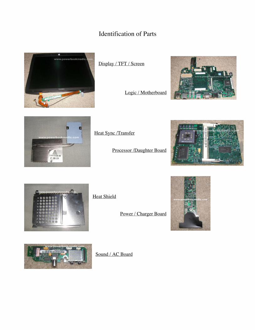
Identification of Parts
Display / TFT / Screen
Logic / Motherboard
Heat Sync /Transfer
Processor /Daughter Board
Heat Shield
Power / Charger Board
Sound / AC Board

Required Tools
Torx T8 Screwdriver – available from www.powerbookmedic.com
Flathead Screwdriver & or Philips Head Screwdriver
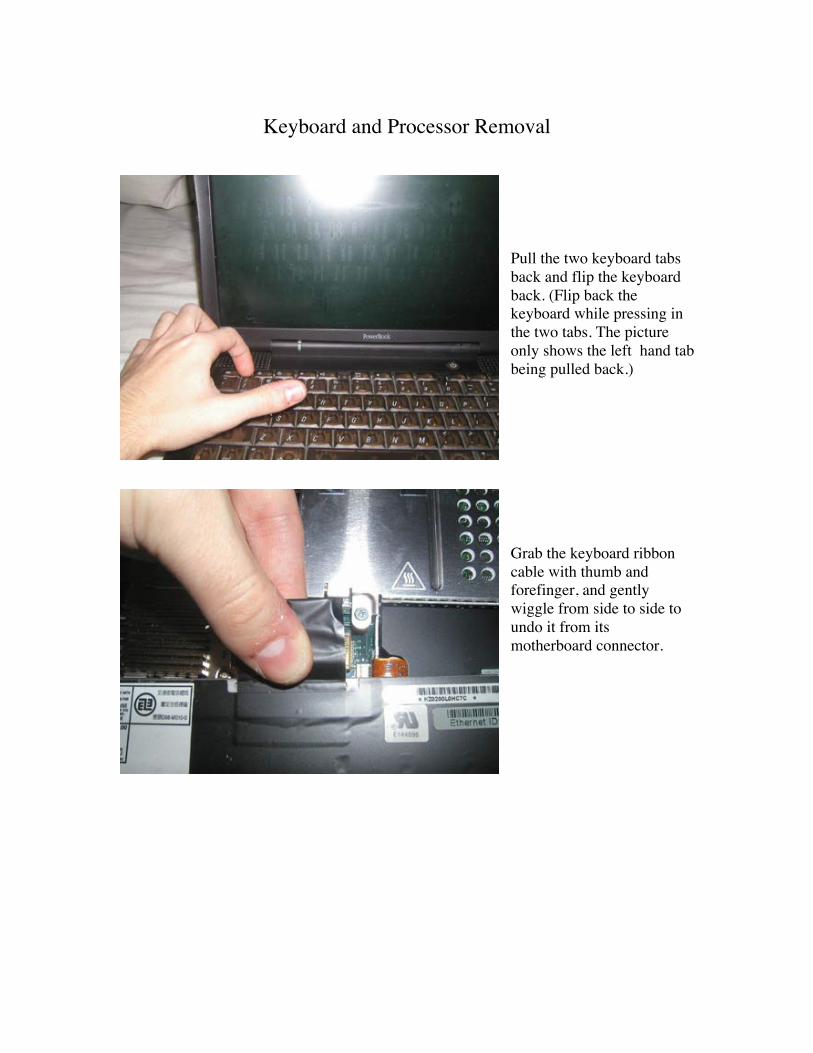
Keyboard and Processor Removal
Pull the two keyboard tabsback and flip the keyboardback. (Flip back thekeyboard while pressing inthe two tabs. The pictureonly shows the left hand tabbeing pulled back.)
Grab the keyboard ribboncable with thumb andforefinger, and gentlywiggle from side to side toundo it from itsmotherboard connector.
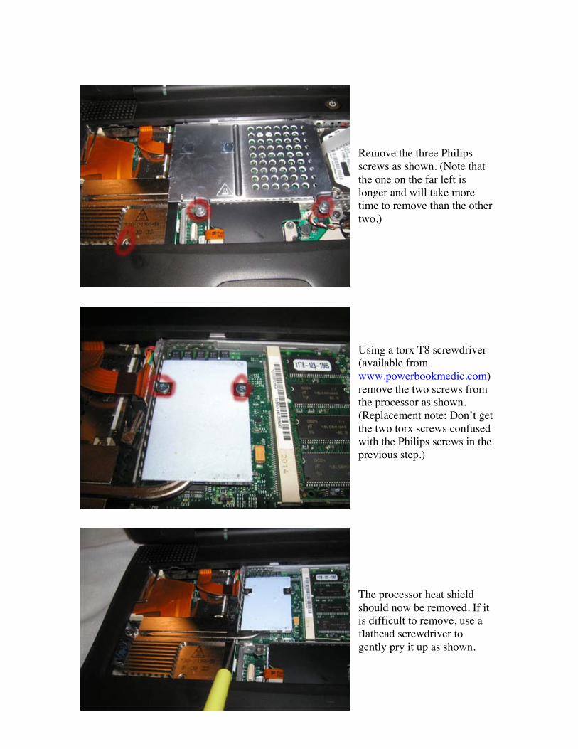
Remove the three Philipsscrews as shown. (Note thatthe one on the far left islonger and will take moretime to remove than the othertwo.)
Using a torx T8 screwdriver(available fromwww.powerbookmedic.com)remove the two screws fromthe processor as shown.(Replacement note: Don’t getthe two torx screws confusedwith the Philips screws in theprevious step.)
The processor heat shieldshould now be removed. If itis difficult to remove, use aflathead screwdriver togently pry it up as shown.

Processor Removal
To remove the processor, putthe flathead screwdriver onthe right hand side of theprocessor as shown. Thengently pry up until theprocessor pops out. *Do notuse too much pressure. If theprocessor does not easilycome out, simply try anotherlocation in the bottom righthand corner. It should berelatively easy to pop out.
Remove the processor asshown, and place on a staticfree surface.
Ram Replacement
Note – To change the ram inthe upper slot you do notneed to remove theprocessor. You only need tofor the bottom slot.Using either a flat headscrewdriver or yourfingernail, pry back the metalfasteners holding in the ramas shown. Do this on eachside. It’s easier if you dothem at the same time. Toinstall new ram, align thegrooves, slide in, and pushdown.
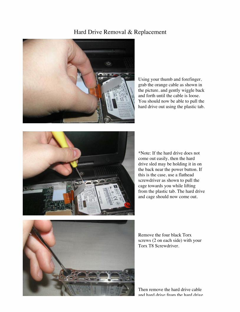
Hard Drive Removal & Replacement
Using your thumb and forefinger,grab the orange cable as shown inthe picture, and gently wiggle backand forth until the cable is loose.You should now be able to pull thehard drive out using the plastic tab.
*Note: If the hard drive does notcome out easily, then the harddrive sled may be holding it in onthe back near the power button. Ifthis is the case, use a flatheadscrewdriver as shown to pull thecage towards you while liftingfrom the plastic tab. The hard driveand cage should now come out.
Remove the four black Torxscrews (2 on each side) with yourTorx T8 Screwdriver.
Then remove the hard drive cableand hard drive from the hard drivesled. You must now remove the
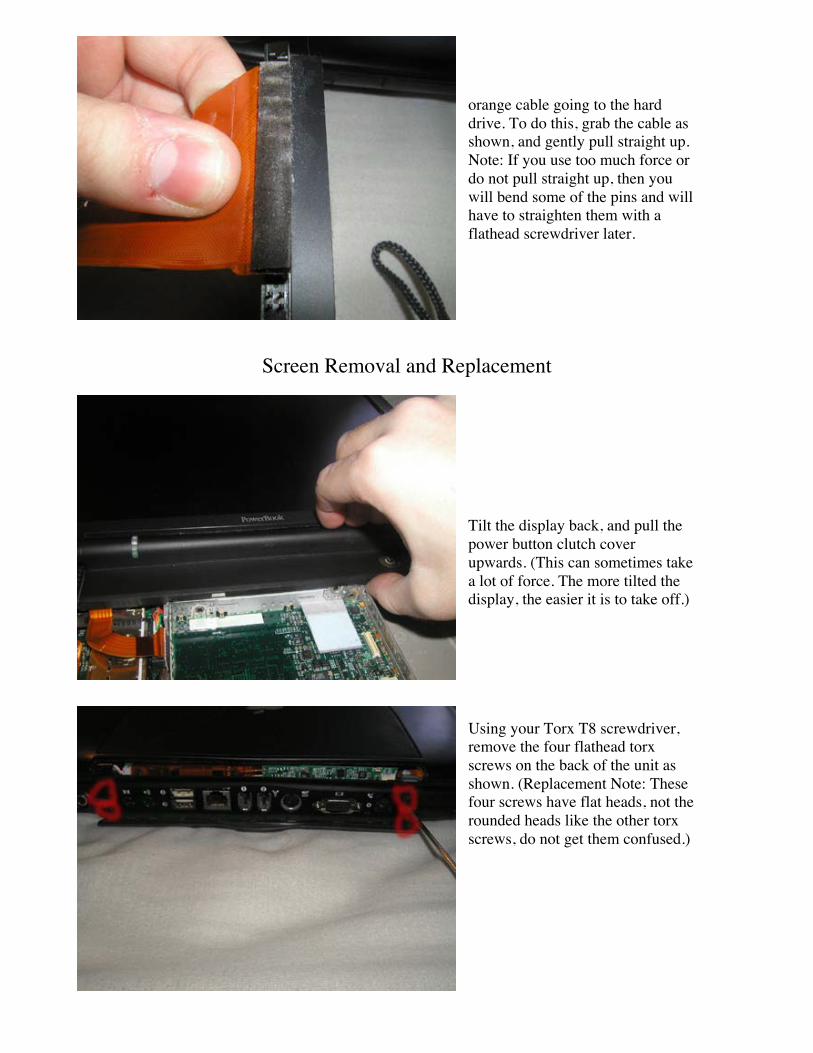
orange cable going to the harddrive. To do this, grab the cable asshown, and gently pull straight up.Note: If you use too much force ordo not pull straight up, then youwill bend some of the pins and willhave to straighten them with aflathead screwdriver later.
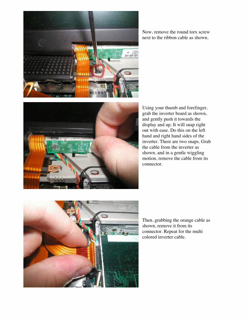
Screen Removal and Replacement
Tilt the display back, and pull thepower button clutch coverupwards. (This can sometimes takea lot of force. The more tilted thedisplay, the easier it is to take off.)
Using your Torx T8 screwdriver,remove the four flathead torxscrews on the back of the unit asshown. (Replacement Note: Thesefour screws have flat heads, not therounded heads like the other torxscrews, do not get them confused.)
Now, remove the round torx screwnext to the ribbon cable as shown.
Using your thumb and forefinger,grab the inverter board as shown,and gently push it towards thedisplay and up. It will snap rightout with ease. Do this on the lefthand and right hand sides of theinverter. There are two snaps. Grabthe cable from the inverter asshown, and in a gentle wigglingmotion, remove the cable from itsconnector.
Then, grabbing the orange cable asshown, remove it from itsconnector. Repeat for the multicolored inverter cable.

Now, pull the display back up so itis perfectly vertical. Place yourhands on the right hand and lefthand side of the monitor, and liftthe display out of the casing.
Display Disassembly
Skip this section if you are repairing something other than the display!
To begin, there are six screws thatneed to be removed from the front ofthe display. These screws are locatedat the positions shown in red. Notethat at each of these locations thereis a screw covering that must first beremoved to get to the screws. Thetop four screws have a rubberstopper, and the bottom two screwshave a very thin plastic covering.
Begin by removing the screwcoverings. This is done by getting aflat head tool (such a flatheadscrewdriver or plastic nylon tool)and prying up from the sides of thecoverings as shown. They shouldcome out easily.

Be careful with the bottom twocoverings. These are very flimsy andeasily damaged. (If damaged, it is onlya cosmetic issue.)
Now, remove the 6 philip head screwslocated at the 6 positions under thescrew coverings.
With the screws removed, you canremove the back lid of the display.
Start at a bottom corner, and pull theback lid apart from the top lid. Youwill have to use a little force to pullthe back lid off. You may also need tostart off by prying the two pieces apartwith a flathead screwdriver or nylontool if you are having a great deal oftrouble.
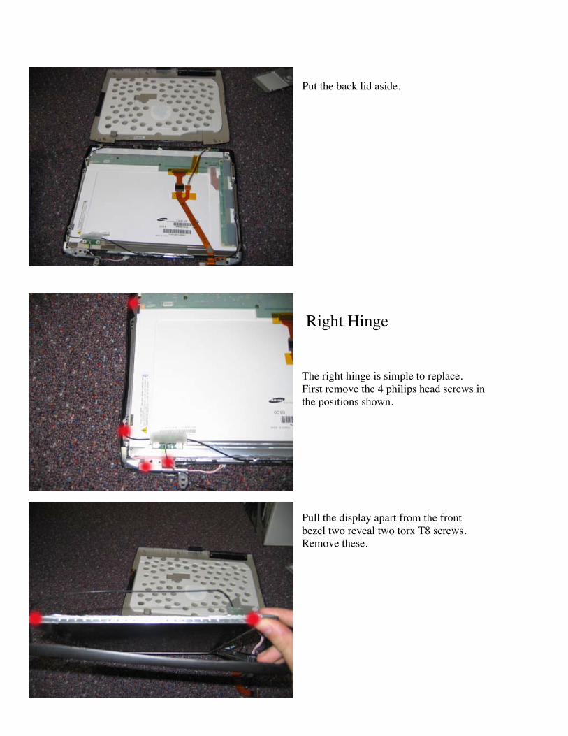
Put the back lid aside.
Right Hinge
The right hinge is simple to replace.First remove the 4 philips head screws inthe positions shown.
Pull the display apart from the frontbezel two reveal two torx T8 screws.Remove these.

The hinge will come out easily.
First remove the two silver Philips headscrews on the metal piece that the airportcable runs to. (You need to remove thesenow or they will be very difficult toremove later. (If only replacing thedisplay cable, you don’t need to removethese screws!)
Remove the 4 philips head screws in thepositions shown.
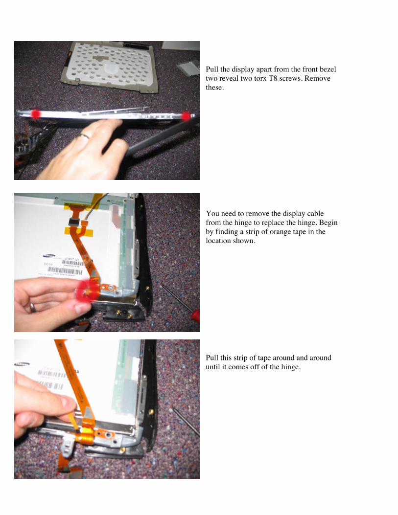
Pull the display apart from the front bezeltwo reveal two torx T8 screws. Removethese.
You need to remove the display cablefrom the hinge to replace the hinge. Beginby finding a strip of orange tape in thelocation shown.
Pull this strip of tape around and arounduntil it comes off of the hinge.

Unwrap the cable from the hinge bypulling the cable towards you and thenunder the hinge.
Pull the cable off the hinge, and the hingewill be free to replace, or you can continueto remove the display cable and LCD.
Remove the two pieces of orange statictape in the locations shown.

Remove the multicolored cable from theorange display cable.
Now disconnect the display cable from theLCD.
The Display cable can now be set aside orreplaced.
LCD Removal
Remove the piece of orange static tape inthe location shown.
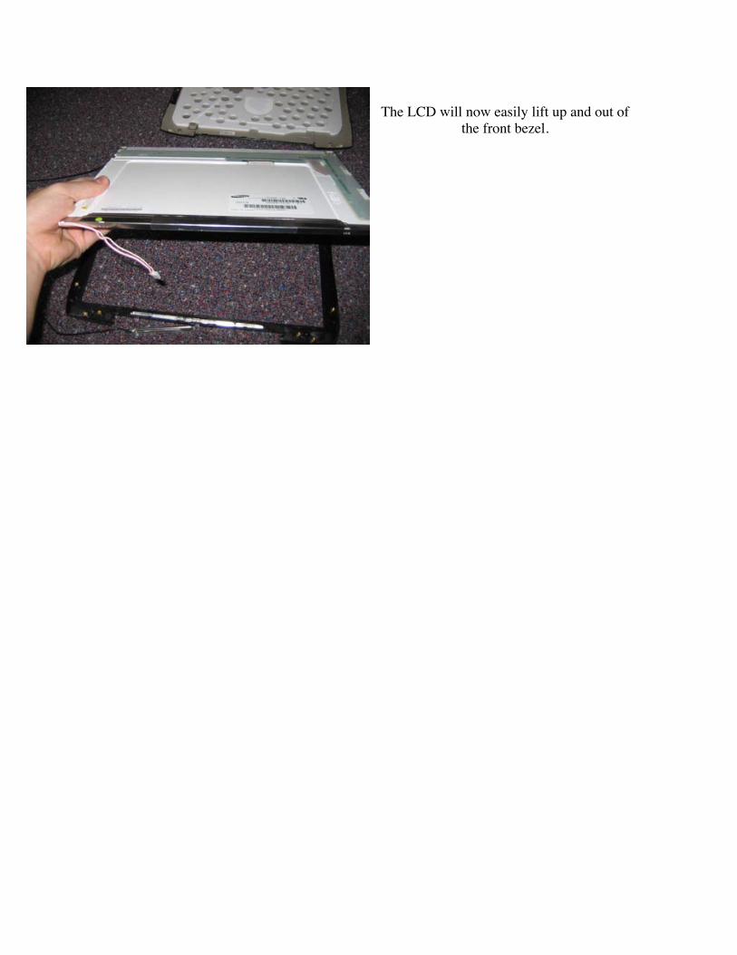
The LCD will now easily lift up and out ofthe front bezel.

Bottom Casing Removal
Modem Removal
Remove the black torx screw as shown.
Then using a flathead screwdriver,gently pry up the modem as shown.
After the modem is loose, remove thecable from the modem, and place themodem on a static free surface.
Trackpad Removal

Remove the 4 torx screws as shown.(There are 3 long silver screws, and 1short black one.
Using your forefinger, slide the blackplastic sheet from under the trackpad asshown.
This reveals the orange trackpad cable.Using your thumb and forefinger, gentlywiggle the orange connector cable from itsconnector.

Pull this cable back to expose onesilver screw. Using your torx T8screwdriver, remove this screwalong with the visible one to theright of it. (Both are long silverscrews.)
Remove the last torx screw asshown.
Remove the seven torx screws asshown. (Replacement note, the twolonger torx screws go on the farleft and right hand side of the areaunder the trackpad as shown)

Remove the two cables from the SoundAC board as shown. (Note these areharder to remove than previous cables.Using needle nose pliers, and grabbingon to the connector and then pullingtowards you may help. If you do this,remember to be gentle.)
The casing will now easily come off.Work your way around the entire unitpulling up on the casing as shown. Startat the back right-hand corner, and workyour way around to the back left-handcorner. Be gentle. If it doesn’t come upeasily, then double check to make sureyou didn’t miss a screw.
Before the trackpad can come off, youmust remove the orange airport cable.Using your thumb and forefinger,Gently wiggle off the airport connectorfrom the motherboard.
Now the trackpad can be taken off.
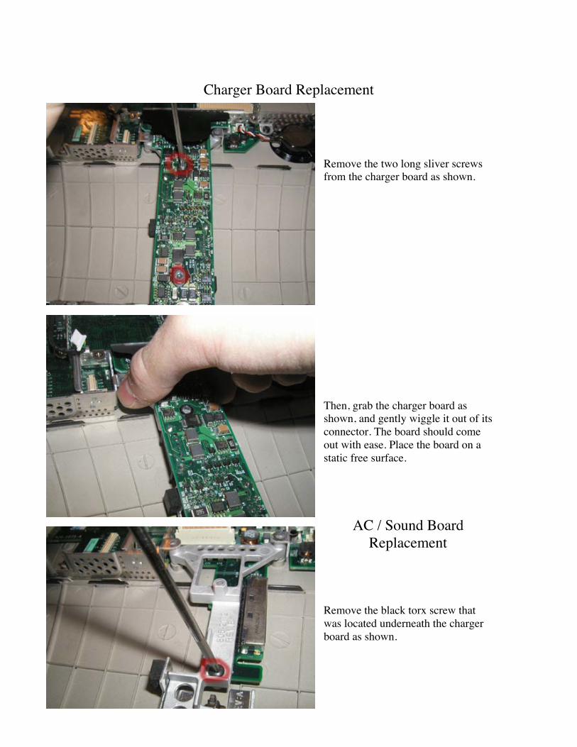
Charger Board Replacement
Remove the two long sliver screwsfrom the charger board as shown.
Then, grab the charger board asshown, and gently wiggle it out of itsconnector. The board should comeout with ease. Place the board on astatic free surface.
AC / Sound BoardReplacement
Remove the black torx screw thatwas located underneath the chargerboard as shown.

Remove the short black torx screwlocated to the right of the PCMCIAcard cage, and the short black torxscrew located next to the Prambattery.
Pull the rib frame out and fold backas shown,

Then remove the cable coming fromthe modem port.
Now gently pull the sound board upand out as shown.
Logic BoardReplacement
Disconnect the Pram battery andfan from their connectors. Removethe small torx screw located nextto the fan connector.
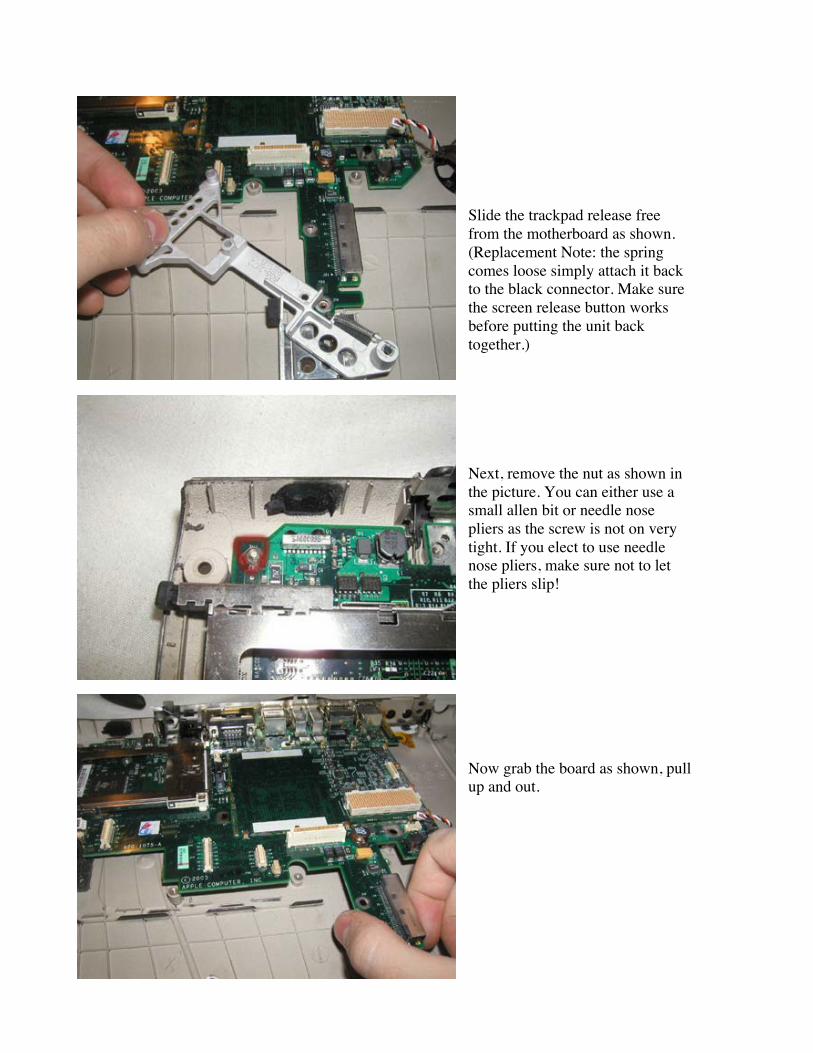
Slide the trackpad release freefrom the motherboard as shown.(Replacement Note: the springcomes loose simply attach it backto the black connector. Make surethe screen release button worksbefore putting the unit backtogether.)
Next, remove the nut as shown inthe picture. You can either use asmall allen bit or needle nosepliers as the screw is not on verytight. If you elect to use needlenose pliers, make sure not to letthe pliers slip!
Now grab the board as shown, pullup and out.

At Powerbookmedic.com, we strive to make our manuals as accurate as possible. If youwould like to see something in this manual or would like to see something improved in
this manual, please email us at: [email protected]
For all of your powerbook & ibook parts and repair needs, visit us at:
Copyright © 2003 Powerbookmedic.com. All rights reserved.