power transmission valves...8 09/10/2019 anti slipping valves - power transmission poclain...
TRANSCRIPT

T E C H N I C A L C A T A L O G
P O W E R TR A N S M IS S IO N V A LV E S

2 09/10/2019
Power transmission POCLAIN HYDRAULICS
Methodology :This document is intended for manufacturers of machines that incorporate Poclain Hydraulics products. It describes the technical characteristics of Poclain Hydraulics products and specifies installation conditions that will ensure optimum operation. This document includes important comments concerning safety. They are indicated in the following way:
This document also includes essential operating instructions for the product and general information. These are indicated in the following way:
The views in this document are created using metric standards. The dimensional data is given in mm and in inches (inches are given in brackets in italic)
Safety comment.
Essential instructions.
General information .
Information on the model number.
Weight of component without oil.
Volume of oil.
Units.
Tightening torque.
Screws.
Information intended for Poclain-Hydraulics personnel.

09/10/2019 3
CONTENTPOCLAIN HYDRAULICS Power transmission
Exch
ange
val
ves
Free
whe
elin
g va
lves
Flow
div
ider
sA
nti-s
lippi
ng v
alve
sPr
essu
re re
duci
ng
valv
eD
irect
iona
l con
trol
va
lves
DIRECTIONAL CONTROL VALVES 73
PRESSURE REDUCING VALVE 67
FLOW DIVIDERS 45
FREEWHEELING VALVES 35
EXCHANGE VALVES 15
ANTI-SLIPPING VALVES 5

4 09/10/2019
Power transmission POCLAIN HYDRAULICS

09/10/19 5
POCLAIN HYDRAULICS Power transmission - Anti slipping valves
CCONTENT
Ant
i-slip
ping
/Sm
artD
rive™
val
ve V
MA
H15
Ant
i-slip
ping
/Tw
inLo
ck™
val
ve V
DP
H10
Anti-slipping/TwinLock™ valve VDP H10 11
Anti-slipping/SmartDrive™ valve VMA H15 7
ANTI-SLIPPING VALVES

6 09/10/19
Anti slipping valves - Power transmission POCLAIN HYDRAULICS

09/10/2019 7
POCLAIN HYDRAULICS Power transmission - Anti slipping valves
Ant
i-slip
ping
/Sm
artD
rive™
val
ve V
MA
H15
Ant
i-slip
ping
/Tw
inLo
ck™
val
ve V
DP
H10
ANTI-SLIPPING/SMARTDRIVE™ VALVE VMA H15
The valves must be supplied in G with a pressure between 15-30 bar [217-435 PSI]. Maximum flow, from P to A or B, for a fully open valve, is 120 L/min [31.7 GPM] per wheel with a pressure diference (P) of 5 bar [72 PSI]. (96 cSt mineral oil at 25 °C [77 °F].
• Anti-slipping• Electronically managed• Programmable
Operation Hydraulic symbolThe anti-slipping valve is an electronically managed traction control, which operates to restrict flow only when slippage is detected, by using normally wheel speed sensors and open proportional valves.
Entirely programmable, the system easily accommodates varying motor displacements and vehicle steering geometry to offer optimal performance.
Features
HydraulicMax. pressure bar [PSI] 450 [6 526]
Nominal flow range L/min [GPM] up to 240 [63.4]
Max restricted flow L/min [GPM] 50 [13.2]Type of hydraulic connections ISO 6162 (Bride SAE) / ISO 9974-1 (Metric) / ISO 11926-1 (UNF)Mass• piped version• flanged version
kg [lb] 7,2 [15.9]11,9 [26.2]
Fluid temperature °C [°F] -20 to +70 [- 4 to +158]
Fluid viscosity mm2/s [ssu] 15 to 380 [69.5 to 1 760]Fluid contamination ISO 4406 18/16/13
ElectricalSolenoid supply voltage V direct 12 24Solenoid current MA 1500 750Type of control mA PWM 100 Hz recommended
Pressure drop
M1 A
E1
E2
FPG
M2 B
Pr
Pr
0 20 40 60 80 100
0.0 5.3 10.6 15.9 26.4 21.1
Q [L/min]
[GPM]
120 140
8
6
5
4
3
2
1
0
7
116
87
73
58
44
29
15
102
0
31.7 36.9
[bar] [PSI]

8 09/10/2019
Anti slipping valves - Power transmission POCLAIN HYDRAULICS
Dimension for piped version
Installation
Hydraulic connectionsOption 1 Option A Max. pressure
bar [PSI] N.M.Port Function Connections Standards Connections StandardsP HP function DN 25 PN400 ISO 6162 DN 25 PN400 ISO 6162 450 [6 526] 90
A-B HP function M27x2 ISO 9974-1 1 1/16-11UNF-2B ISO 11926-1 450 [6 526] 200
F Drain M14x1.5 ISO 9974-1 9/16-18 UNF-2B ISO 11926-1 1 [14.5] 45G LP supply M14x1.5 ISO 9974-1 9/16-18 UNF-2B ISO 11926-1 15<P<30 45
M1-M2 Pressure measurement M14x1.5 ISO 9974-1 M14x1.5 ISO 9974-1 0<P<20 45
16[0.63]
81 [3
.19]
55 [2
.17]
28[1
.10]
20[0
.79]
16[0
.63] 39
[1.54]50
[1.97 ]
+0,2-0,2
+0.007-0.007
100
[3.9
4]
92 [3
.62]
89,5 [3.52]
118 [4.65]
64 [2.52]16
[0.63]
256 [10.08]
132
[5.1
9]
124
[4.8
8]
2xM10x2
Serial number
5H - - 11 -AV -M -
T2 31
F2 31
P2 31
Q2 31
C2 31 4 5
S2 31 4
N.m [lb.ft]2xM10 8.8 49 [36]
Class (*)
(*) As per standard DIN 912Mounting position: Indifferent
Motor and valve drain piping must be connected directly to the tank.

09/10/2019 9
POCLAIN HYDRAULICS Power transmission - Anti slipping valves
Ant
i-slip
ping
/Sm
artD
rive™
val
ve V
MA
H15
Ant
i-slip
ping
/Tw
inLo
ck™
val
ve V
DP
H10
Dimension for flanged version
Installation
Hydraulic connectionsOption 4 Option A Max. pressure
bar [PSI] N.M.Port Function Connections Standards Connections StandardsP HP function flanged Ø25 [dia. 0.98] 450 [6 526]A-B HP function flanged Ø16 [dia. 0.63] 450 [6 526]F Drain M14x1.5 ISO 9974-1 9/16-18 UNF-2B ISO 11926-1 1 [14.5] 45G LP supply M14x1.5 ISO 9974-1 9/16-18 UNF-2B ISO 11926-1 15<P<30 45
M1-M2 Pressure measurement M14x1.5 ISO 9974-1 M14x1.5 ISO 9974-1 0<P<20 45
A
G
M1 YYY
37[1
.46]
37[1
.46]
126
[4
.96
]
150
[5.9
1]
256 [10.07]
96,5 [3.79]97,5 [3.84]
81,5 [3.21]
55 [2.17]
9 [0.35]33 [1.29]44 [1.73]
20,5 [0.80]
62 [2.44]66 [2.59]
4 [0.16]16 [0.62]
+0,3
-0,3
+0.0
1-0
.01
4 [0
.16]
16 [0
.62]
4xM12
M12 z=4
Ø6
[0.2
4 di
a.]
E1,E2
E1
E2
B
FP
5H - - 11 -AV -M -
T2 31
F2 31
P2 31
Q2 31
C2 31 4 5
S2 31 4
44±0,2[1.73±0.01]
11 [0.43]
63±0
,2[2
.48±
0.01
]
150
min
. [5.
90 m
in.]
126±
0,2
[4.9
6±0.
01]
24±0,2 [0.94±0.01]73 min.
[2.87 min.]9±0,2 [0.35±0.01]
Ø16 max. [max. 0.63 dia.]
Ø25 max.[max. 0.98 dia.]
4x M12A
B
Ø16 max. [max. 0.63 dia.]
Lug Ø6±0.2[0.24±0.01] Height 4 [0.16]
37±0
,2[1
.45±
0.01
]37
±0,2
[1.4
5±0.
01]
C
C
Z
P
min
. 18
[min
. 0.7
0]X
C-C
Z
c 0,01
Rmax 8
Mating surface quality
N.m [lb.ft]4xM12 8.8 86 [63.5]
Class (*)
(*) As per standard DIN 912Mounting position: Indifferent
Motor and valve drain piping must be connected directly to the tank.
Remove the protection plate.
Make sure that Q-rings are correctly positioned.
Install the valve on the mounting face with the help from the lug.

10 09/10/2019
Anti slipping valves - Power transmission POCLAIN HYDRAULICS
Model code
5H
TypeValve VMultifunctional MAnti-slipping A
- -1 -
Q1 - Q3 High pressure settingWithout 000350 bar [5 076 PSI] 350430 bar [6 237 PSI] 430450 bar [6 526 PSI] 450
S1 - S4 OptionsWithout 0Fluorinated elastomer seals compatible with C and D fluids 1Zinc coated BPainted DCustomized name plate PCustomized component * F* Further description on interface drawing.
AV -M -
F1 - Operating pressureHigh pressure - 450 bar [6 526 PSI] H
F2 - F3 Input / Flowup to 240 L/min [63.4 GPM] 15
P1 - P3 Controled flow20 L/min [5.3 GPM] 02050 L/min [13.0 GPM] 050
C1 - TechnologyWith low pressure protection 1With low/high pressure protection 2
C2 - Fixation typeBlock (to pipping) 1Flange “Poclain Hydraulics” * 6* Flange for mounting
C3 - Control type12V DC 124 V DC 2
C4 - Hydraulic connectionsWithout 0ISO 6162 (Bride SAE) & ISO 9974-1 (Metric) * 1ISO 9974-1 (Metric) ** 4ISO 11926-1 (UNF) A* Only for piped version**Only for flanged version
C5 - ConnectorsWithout 0Deutsch DT04-2P 3AMP Junior Timer (6,3 x 0,8) 5
T2 31
F2 31
P2 31
Q2 31
C2 31 4 5
S2 31 4

09/10/2019 11
POCLAIN HYDRAULICS Power transmission - Anti slipping valves
Ant
i-slip
ping
/Sm
artD
rive™
val
ve V
MA
H15
Ant
i-slip
ping
/Tw
inlo
ck™
val
ve V
DP
H10
AANTI-SLIPPING/TWINLOCK™ VALVE VDP H10
• Anti-slipping• Automatic transfer of torque to the wheels• Maximize wheel ground adhesion
Operation Hydraulic symbolVDP anti-slipping valve provides flow division while automatically transferring torque to the wheels with the greatest ground adhesion. 2 positions 3 positions
Features2 positions 3 positions
Max. pressure bar [PSI] 450 [6 526]Nominal flow range L/min [GPM] 26 to 50 [6.8 to 13.2]Max. restricted flow L/min [GPM] 50 [13.2]Type of hydraulic connection ISO 1179-1 (BSPP)
Mass kg [lbs] 2,65 [5.84] 3,33 [7.34]
Fluid temperature °C [°F] -20 to +70 [-4 to +158]Fluid viscosity mm2/s [SSU] 15 to 380 [69.5 to 1 760]Type of hydraulic connections ISO 1179-1 (BSPP)

Dimensions for 2 positions
- -2-1 0-D PV 01 -1 2 3
T
2 3 1
C
2 3 1 2 3 4
M
5 1 2 3
V
1 2 3 4
S
H1
F
Dimensions for 3 positions command type short
- -3-1 0-D PV 01 -1 2 3
T
2 3 1
C
2 3 1 2 3 4
M
5 1 2 3
V
1 2 3 4
S
H1
F
Dimensions for 3 positions command type long (according to model code)
- -3-1 0-D PV 02 -1 2 3
T
2 3 1
C
2 3 1 2 3 4
M
5 1 2 3
V
1 2 3 4
S
H1
F
12 09/10/2019
Anti slipping valves - Power transmission POCLAIN HYDRAULICS

Installation
N.m [lb.ft]2xM8 8.8 25 [18]
Class (*)
(*) As per standard DIN 912Mounting position: Indifferent1
Hydraulic connections
Port Function ConnectionsMax. pressure
bar [PSI]Nm [lb.ft] ±10 %
(as per standard DIN 912)P-A-B HP function M18x1.5 450 [6 526] 70 [52]X Pilot
M14x1.550 [752]
45 [33]L Drain 3 [45]
The operation of the cam on the roller must be limited ±30° to limit the parasite forces.
Mechanical controlBeginning of opening
N [lbf]End of opening
N [lbf]Max. stroke
mm [in]2 positions 25 [5.62] 55 [12.36] 10 [0.39]3 positions 49 [11.02] 170 [38.22] 16 [0.6]
Hydraulic controlBeginning of opening
bar [PSI]End of opening
bar [PSI]Max. pressure
bar [PSI]2 positions 5 [72.5] 11 [160]
50 [725]3 positions 4 [58] 15 [218]
mm² in²
mm
inbar
PSI
mm² in²
mmin
bar
PSI
09/10/2019 13
POCLAIN HYDRAULICS Power transmission - Anti slipping valves
Ant
i-slip
ping
/Sm
artD
rive™
val
ve V
MA
H15
Ant
i-slip
ping
/Tw
inlo
ck™
val
ve V
DP
H10
2 positions 3 positions

Model code
- --1 0-D PV 0 -
C2 - C3 Debit/Flow26 to 50 L/min [7.0 to 13.0 GPM] 10
F1 - Number of waysThree ways 3
F2 - Number of positionsTwo positions 2Three positions 3
F3 - ProgressivenessWithout 0Type 1 * 1Type 2 * 2Type 3 ** 3* Available only with three positions (F2=3)** Available only with two positions (F2=2)
M1 - TechnologyMonoblock M
M2 - Fixation typeBlock (to piping) 1
M3 - Control typeMechanical roller G
M4 - Hydraulic connectionsISO 1179-1 (BSPP) 3
M5 - ConnectorWithout 0
V1 - Command typeWithout 0Short 1Long 2
V3 - Reserved0
S1 - S4 OptionsWithout 0Painted DZinc coated BCustomized name plate PCustomized * F* Further description on interface drawing
V2 - UseStandard 0With function “road” 1
T1 - T3 TypeValve VDirectional DProgressive P
C1 - Operating pressureHigh pressure 450 bar [6 526 PSI] H
1 2 3
T
2 3 1
C
2 3 1 2 3 4
M
5 1 2 3
V
1 2 3 4
S
H1
F
14 09/10/2019
Anti slipping valves - Power transmission POCLAIN HYDRAULICS

09/10/19 15
POCLAIN HYDRAULICS Power transmission - Exchange valves
CONTENT
Exch
ange
val
ve V
E10
Exch
ange
val
ve V
E30
Hig
h pe
rfor
man
ce
exch
ange
val
ve V
E60
Exch
ange
and
hig
h pr
essu
rere
liefv
alve
VES
60
Exchange valve VE30 21
Exchange valve VE10 17
EEXCHANGE VALVES
High performance Exchange valve VE60 25
Exchange and High pressure relief valve VES60 31

16 09/10/19
Exchange valves - Power transmission POCLAIN HYDRAULICS

09/10/19 17
POCLAIN HYDRAULICS Power transmission - Exchange valves
Exch
ange
val
ve V
E10
Exch
ange
val
ve V
E30
Hig
h pe
rfor
man
ce
exch
ange
val
ve V
E60
Exch
ange
and
hig
h pr
essu
rere
liefv
alve
VES
60
EEXCHANGE VALVE VE10
• Compact• Heavy duty
Operation Hydraulic symbolExchange valves are for use in bleeding hot oil from the low pressure side of a hydrostatic transmission circuit. The hot oil can be cooled, filtered or used as a source of oil for flushing other pump and motor case.
Features
Max. pressure bar [PSI] 450 [6 526]Exchange relief valve setting bar [PSI] 12; 14; 16; 18; 20 [174; 203; 232; 261; 290]Selector spool switching pressure bar [PSI] 8,5 [123]Exchange flow (11 bar [160 PSI] P) L/min [GPM] max.15 [3.96] ( P A T or B T)Exchange direction Forward and/or reverseType of hydraulic connections ISO 9974-1 (BSPP) / ISO 1179-1 (Metric) / ISO 11926-1 (UNF)Mass kg [lbs] 1,1 [2.43]
Operation
Q [L/min]
Example: relief valve set at 20 bar [290 PSI]
Pressure drop
P [bar]

Dimensions
B
A
T
0 0- -0E -1V 0000 01 -1 2 3 4
T
1 2 3 4
P
5 6 1 2 3 4
C
5 1 2 3
M
1 2 3 4
S
Hydraulic connections
Port FunctionConnections
Max. pressurebar [PSI]ISO 9974-1 (Metric)
Type NISO 1179-1 (BSPP)
Type NISO 11926-1
(UNF)A HP/LP connection
M18 x 1.5 G3/8 9/16-18 UNF-2B450 [6 526]
B HP/LP connectionT Tank connection 5 [72.5]
18 09/10/19
Exchange valves - Power transmission POCLAIN HYDRAULICS

Model code
0 0- -0E -1V 0000 01 -
P1 - Exchange directionUnidirectional (A T) ABidirectional C
P2 - P3 Exchange opening pressure12 bar [174 PSI] 1214 bar [203 PSI] 1416 bar [232 PSI] 1618 bar [261 PSI] 1820 bar [290 PSI] 20
P4 - Type of exchangeRelief valve not adjustable - fixed by wire 0
P5 - P6 Restrictor diameterWithout 001,0 mm [0.039 in] 101,2 mm [0.047 in] 121,4 mm [0.055 in] 141,6 mm [0.063 in] 161,8 mm [0.071 in] 18
C1 - C5 Mechanic setting rangeWithout 00000
M1 - Assembly versionPiped block 1
M3 - Pressure gauge portWithout 0
S1 - S4 OptionsWithout 0Painted DZinc coated BCustomized name plate PCustomized * F* Further description on interface drawing
M2 - Hydraulic connectionsISO 1179-1 (BSPP) G3/8 BSPP 3ISO 9974-1 (Metric) M18x1.5 4ISO 11926-1 (UNF) 9/16-18 UNF-2B A
T1 - T2 TypeValve VExchange E
T3 - T4 Max. flow10 L/min [2.64 GPM] 10
1 2 3 4
T
1 2 3 4
P
5 6 1 2 3 4
C
5 1 2 3
M
1 2 3 4
S
09/10/19 19
POCLAIN HYDRAULICS Power transmission - Exchange valves
Exch
ange
val
ve V
E10
Exch
ange
val
ve V
E30
Hig
h pe
rfor
man
ce
exch
ange
val
ve V
E60
Exch
ange
and
hig
h pr
essu
rere
liefv
alve
VES
60

20 09/10/19
Exchange valves - Power transmission POCLAIN HYDRAULICS

09/10/2019 21
POCLAIN HYDRAULICS Power transmission - Exchange valves
Exch
ange
val
ve V
E10
Exch
ange
val
ve V
E30
Hig
h pe
rfor
man
ce
exch
ange
val
ve V
E60
Exch
ange
and
hig
h pr
essu
rere
liefv
alve
VES
60
EEXCHANGE VALVE VE30
• Compact• Adjustable• Heavy duty
Piped valve Flanged valve
Features Hydraulic symbol
Exchange valves are for use in bleeding hot oil from the low pressure side of a hydrostatic transmission circuit. The hot oil can be cooled, filtered or used as a source of oil for flushing other pump and motor case.
Features
Max. pressure bar [PSI] 500 [7 252]Exchange relief valve setting bar [PSI] 10 to 30 [145 to 435]Selector spool switching pressure bar [PSI] 8 [116]Exchange flow (10 bar [145 PSI] P) L/min [GPM] 30 [7.93] ( P A T or B T)Exchange direction Forward and/or reverseType of hydraulic connections ISO 1179-1 (BSPP) / ISO 9974-1 (Metric) / ISO 11926-1 (UNF)Mass kg [lbs] 1,5 [3.31]
Pressure drop P-Q Performance curves
Q [L/min]
Example: relief valve set at 20 bar [290 PSI]
Pressure drop
P [bar]4540
35
30
25
20
15
10
5
00 3 6 9 12 15 18 21 24 27 30
P[b
ar]
Q [L/min]
A, B to T - 30 bar [435 PSI]A, B to T - 10 bar [145 PSI]
Adjustable area

Dimensions for piped valve
54 [2.12]16 [0.63]
40 [1
.57]
16 [0
.63]
S=4
S=13; Md=24+2 Nm
145,
5 m
ax. [
max
. 5.7
3]12
2,5
[4.8
2]
60 [2.36] 5 [0.20]
70 [2.75]
35 [1.38]
18[0.71] 11,5 [0.45]
77 [3
.03]
56 [2
.20]
22 [0
.87]
5[0
.20]
2x Ø5,6[2 x dia.0.22]
BA
T
M
UNF connections
Metric connections
0 - -00E -3V 0 1 -1 2 3 4
T
1 2 3 4
P
5 6 1 2 3 4
C
5 1 2 3
M
1 2 3 4
S
22 09/10/2019
Exchange valves - Power transmission POCLAIN HYDRAULICS

Hydraulic connections
Port Function
ConnectionMax. pressure
bar [PSI]ISO 9974-1
(Metric)Type N
ISO 1179-1 (BSPP)Type N
ISO 11926-1 (UNF)
A HP/LP connection
M18 x 1.5 G3/8 3/4-16 UNF-2B500 [7 252]
B HP/LP connection
Mpressure measurementor service connection
T Tank connection 5 [72.5]
Dimensions for flanged valve
93 [3.66]
70 [2.75]
56±0,2[2.20±0.008]
121,
5 [4
.78]
144,
5 m
ax. [
max
. 5.6
9]
62±0
,2 [2
.44±
0.00
8]76
[2.9
9]7
[0.2
7]
7 [0.27]
11,5 [0.45]
4x Ø6,6 [4 x dia.0.26]
35 [1.38]
s=4
s=13; Md=24+2 Nm
37±0
,1[1
.45±
0.00
4]9,
7±0,
1 [0
.38±
0.00
4]
14±0,01[0.55±0.0004]
28±0,1[1.10±0.004]
42±0,1[1.65±0.004]
B
A
T
0 - -00E -3V 0 6 -1 2 3 4
T
1 2 3 4
P
5 6 1 2 3 4
C
5 1 2 3
M
1 2 3 4
S
Hydraulic connections
Port Function Connection Max. pressurebar [PSI]
A HP/LP connection Ø 7 mm[dia. 0.27 in] 500 [7 252]
B HP/LP connection
T Tank connection Ø 9 mm[dia. 0.35 in] 5 [72.5]
09/10/2019 23
POCLAIN HYDRAULICS Power transmission - Exchange valves
Exch
ange
val
ve V
E10
Exch
ange
val
ve V
E30
Hig
h pe
rfor
man
ce
exch
ange
val
ve V
E60
Exch
ange
and
hig
h pr
essu
rere
liefv
alve
VES
60

Model code
0 - -00E -3V -
P1 - Exchange directionUnidirectional (A T) AUnidirectional (B T) BBidirectional C
P2 - P3 Exchange opening pressure10 bar [145 PSI] 1012 bar [174 PSI] 1214 bar [203 PSI] 1416 bar [232 PSI] 1618 bar [261 PSI] 1820 bar [290 PSI] 2022 bar [319 PSI] 2224 bar [348 PSI] 2426 bar [348 PSI] 2628 bar [406 PSI] 2830 bar [435 PSI] 30
P4 - Type of exchangeRelief valve not adjustable - fixed by wire 0Relief valve adjustable A
P5 - P6 Restrictor diameterWithout 00
C1 - C5 Mechanic setting rangeLow range: 10 to 20 bar [145 to 290 PSI] 01020High range: 20 to 30 bar [290 to 435 PSI] 02030
M1 - Assembly versionPiped block 1Flanged block (A, B, T) 6
M3 - M portWithout 0Open ** M** Only available with piped valve
S1 - S4 OptionsWithout 0Painted DZinc coated BCustomized name plate PCustomized * F* Further description on interface drawing
M2 - Hydraulic connectionsWithout (when M1=6) 0ISO 1179-1 (BSPP) 3ISO 9974-1 (Metric) 4ISO 11926-1 (UNF) A
T1 - T2 TypeValve VExchange E
T3 - T4 Max. flow30 L/min [7.93 GPM] 30
1 2 3 4
T
1 2 3 4
P
5 6 1 2 3 4
C
5 1 2 3
M
1 2 3 4
S
24 09/10/2019
Exchange valves - Power transmission POCLAIN HYDRAULICS

09/10/19 25
POCLAIN HYDRAULICS Power transmission - Exchange valves
Exch
ange
val
ve V
E10
Exch
ange
val
ve V
E30
Hig
h pe
rfor
man
ce
exch
ange
val
ve V
E60
Exch
ange
and
hig
h pr
essu
rere
liefv
alve
VES
60
HHIGH PERFORMANCE EXCHANGE VALVE VE60
• Compact• Adjustable• Heavy duty
Flanged version Piped version
Operation Hydraulic symbols
Exchange valves are for use in bleeding hot oil from the low pressure side of a hydrostatic transmission circuit. The hot oil can be cooled, filtered or used as a source of oil for flushing other pump and motor case.
Type of exchange: F Type of exchange: 0 and A
FeaturesFlanged version Piped version
Max. pressure bar [PSI] 500 [7 252]Exchange relief valve setting bar [PSI] 12 to 30 [174 to 435]Selector spool switching pressure bar [PSI] 8 [116]Exchange flow (10 bar [145 PSI] P) L/min [GPM] 60 [15.9]Exchange direction Forward and/or reverseType of hydraulic connections ISO 1179-1 (BSPP) / ISO 9974-1 (Metric) / ISO 11926-1 (UNF)Mass kg [lbs] 2,4 [5.29] 3,2 [7.05]
Pressure drop P-Q Performance curves
Q [L/min]
Example: Relief valve set at 20 bar [290 PSI].
Pressure drop
P [bar] 45
40
35
30
25
2015
10
50
0 10 20 30 40 50 60
P[b
ar]
Q [L/min]
A, B to T - 30 bar [435 PSI]A, B to T - 12 bar [173 PSI]
Adjustable area

Dimensions for piped version
66,5 [2.62]
61,5
[2.4
2]
57
[2.2
4] 2
5,5
[1.0
0]
91,5 [3.60]
S=4
S=13Ma=24+2 Nm
67,5 [2.66] 23,5 [0.93]
124
[4.8
8]
27,5 [1.08]
114 [4.49] max. 27 [1.06]max. 173 [6.81]
55 [2
.17]
86±0
,2 [3
.39±
0.00
8]
98 [3
.86]
7
[0
.28]
25,5 [1.00]
34,
5 [1
.00]
75,5
[2.9
7]
66,5 [2.62]
25,5
[1.0
0]
15,
5 [0
.61]
2x Ø13,5 [0.53 dia.]2x Ø8,5 [0.33 dia.]
MB
MA
A
B
M
AA
A-A
M
max. 173 [6.81]
4,5 [0.18]
141 [5.55]
Type of exchange - A Type of exchange - 0 Type of exchange - F
0 - -00E -6V 2 -1 2 3 4
T
1 2 3 4
P
5 6 1 2 3 4
C
5 1 2 3
M
1 2 3 4
S
Hydraulic connections
Port FunctionConnection
Max. pressurebar [PSI]ISO 9974-1 (Metric)
Type NISO 1179-1 (BSPP)
Type N ISO 11926-1 (UNF)
A HP/LP connectionM22x1.5 G1/2 7/8-14 UNF-2B
500 [7 251]B HP/LP connectionT Tank connection 5 [72.5]
MA Pressure measurement (A)M14x1.5 G1/4 9/16-18 UNF-2B 500 [7 251]
MB Pressure measurement (B)
M Pressure measurement or service connection M22x1.5 G1/2 7/8-14 UNF-2B 500 [7 251]
26 09/10/19
Exchange valves - Power transmission POCLAIN HYDRAULICS

Dimensions for flanged version
max. 175 [6.89]
143 [5.63]
c
max. 175 [6.89]114 [4.49]
124
[4.8
8]
73,4
[2.8
9]
34[1.34]
max. 27 [1.06]
32,7
[1.2
9]9
[0.3
5]
55 [2
.17]
50,5
[1.9
9]
26,5
[1.0
4]
24[0
.94]
15[0
.59]
85,5
[3.3
7]
72,8
[2.8
7]53
[2.0
9]
A
T
B
MA
MB
33,2
[1.3
1]
65 ±
0,2
[2
.56
± 0.
008]
24,2 [0.95]
0,01
Rmax 8
4x Ø8,5[dia. 0.33]
4x Ø13,5[dia. 0.53]
S=4S=13Ma=24+2 Nm
A A
A-A
2 [0.08]10,7 [0.42]
48,4±0,2[1.91±0.008]
2 [0.08]
2,3
± 0,
1[0
.09
± 0.
004]
Mating surface quality
Type of exchange - 0 Type of exchange - FType of exchange - A
0 - -00E -6V 07 -1 2 3 4
T
1 2 3 4
P
5 6 1 2 3 4
C
5 1 2 3
M
1 2 3 4
S
Hydraulic connections
Port FunctionConnection
Max. pressurebar [PSI]ISO 9974-1 (Metric)
Type NISO 1179-1
Type N ISO 11926-1
A HP/LP connectionØ14 mm [dia. 0.55 in] Ø14 mm [dia. 0.55 in] Ø14 mm [dia. 0.55 in] 500 [7 251]
B HP/LP connectionT Tank connection Ø10 mm [dia. 0.39 in] Ø10 mm [dia. 0.39 in] Ø10 mm [dia. 0.39 in] 5 [72.5]
MA Pressure measurement (A)M14x1.5 G1/4 BSPP 9/16-18 UNF-2B 500 [7 251]
MB Pressure measurement (B)
09/10/19 27
POCLAIN HYDRAULICS Power transmission - Exchange valves
Exch
ange
val
ve V
E10
Exch
ange
val
ve V
E30
Hig
h pe
rfor
man
ce
exch
ange
val
ve V
E60
Exch
ange
and
hig
h pr
essu
rere
liefv
alve
VES
60

Dimensions with T port piped - optional
85,5
[3.3
7]72
,8 [2
.87]
33,
2 [1
.31]
48,4±0,2[1.91±0.0008]
7,8 [0.31]
65±0
,2[2
.56±
0.00
08]
2,3±
0,1
[0.9
1±0.
0004
]
30 [1.18]
4x Ø13,5 [dia. 0.53]
45 [1
.78]
25
[0.9
8] 2
2 [0
.87]
4x Ø8,5 [dia. 0.33]
max. 181 [7.13]
S=13Ma=24+2 Nm
S=4
80 [3.15]
45 [1.77]
25[0.98]
68 [2
.68]
38 [1
.49]
106 [4.17] 43,5 [1.71] max. 27 [0.98]
4,5 [0.18]
max. 181 [7.13]
9 [0
.35]
106
[4.1
7]
124
[4.8
8]
149 [5.87]
MA
MB
T
A
B
c 0,01
Rmax 8
A A
A-A
Type of exchange - 0 Type of exchange - FType of exchange - A
Mating surface quality
0 - -00E -6V T -1 2 3 4
T
1 2 3 4
P
5 6 1 2 3 4
C
5 1 2 3
M
1 2 3 4
S
Hydraulic connections
Port FunctionConnection
Max. pressurebar [PSI]ISO 9974-1 (Metric)
Type NISO 1179-1 (BSPP)
Type NISO 11926-1
(UNF)A HP/LP connection Ø14 mm
[dia. 0.55 in]Ø14 mm
[dia. 0.55 in]Ø14 mm
[dia. 0.55 in] 500 [7 251]B HP/LP connectionT Tank connection M22x1.5 G1/2 BSPP 7/8-14 UNF-2B 5 [72.5]
MA Pressure measurement (A)M14x1.5 G1/4 BSPP 9/16-18 UNF-2B 500 [7 251]
MB Pressure measurement (B)
28 09/10/19
Exchange valves - Power transmission POCLAIN HYDRAULICS

Model code
0 - -00E -6V -
P1 - Exchange directionUnidirectional (A T) AUnidirectional (B T) BBidirectional C
P2 - P3 Exchange opening pressure12 bar [174 PSI] 1214 bar [203 PSI] 1416 bar [232 PSI] 1618 bar [261 PSI] 1820 bar [290 PSI] 2022 bar [319 PSI] 2224 bar [348 PSI] 2426 bar [377 PSI] 2628 bar [406 PSI] 2830 bar [435 PSI] 30
P4 - Type of exchangeRelief valve adjustable ARelief valve not adjustable - fixed by wire 0Relief valve not adjustable - locked setting F
P5 - P6 Restrictor diameterWithout 00
C1 - C5 Mechanic setting rangeLow range: 12 to 18 bar [174 to 261 PSI] 01218High range: 18 to 30 bar [261 to 435 PSI] 01830
M1 - Assembly versionPiped block - casted body 2Flanged block (A, B, T) - casted body 7Flanged valve with T port piped T
M3 - M portPlugged / Without * 0Open ** M* Plugged - Only when Piped (M1=2)* Without - Only when Flanged (M1=7)** Only when Piped (M1=2)
S1 - S4 OptionsWithout 0Painted DZinc coated BCustomized name plate PCustomized * F* Further description on interface drawing
M2 - Hydraulic connectionsISO 1179-1 (BSPP) 3ISO 9974-1 (Metric) 4ISO 11926-1 (UNF) A
T1 - T2 TypeValve VExchange E
T3 - T4 Max. flow60 L/min [15.85 GPM] 60
1 2 3 4
T
1 2 3 4
P
5 6 1 2 3 4
C
5 1 2 3
M
1 2 3 4
S
09/10/19 29
POCLAIN HYDRAULICS Power transmission - Exchange valves
Exch
ange
val
ve V
E10
Exch
ange
val
ve V
E30
Hig
h pe
rfor
man
ce
exch
ange
val
ve V
E60
Exch
ange
and
hig
h pr
essu
rere
liefv
alve
VES
60

30 09/10/19
Exchange valves - Power transmission POCLAIN HYDRAULICS
09/10/19 31
POCLAIN HYDRAULICS Power transmission - Exchange valves
Exch
ange
val
ve V
E10
Exch
ange
val
ve V
E30
Hig
h pe
rfor
man
ce
exch
ange
val
ve V
E60
Exch
ange
and
hig
h pr
essu
rere
lief v
alve
VES
60
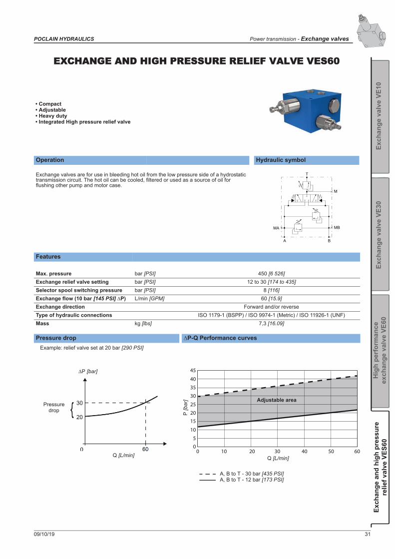
EEXCHANGE AND HIGH PRESSURE RELIEF VALVE VES60
• Compact• Adjustable• Heavy duty• Integrated High pressure relief valve
Operation Hydraulic symbol
Exchange valves are for use in bleeding hot oil from the low pressure side of a hydrostatic transmission circuit. The hot oil can be cooled, filtered or used as a source of oil for flushing other pump and motor case.
T
M
MBMA
A B
Features
Max. pressure bar [PSI] 450 [6 526]Exchange relief valve setting bar [PSI] 12 to 30 [174 to 435]Selector spool switching pressure bar [PSI] 8 [116]Exchange flow (10 bar [145 PSI] P) L/min [GPM] 60 [15.9]Exchange direction Forward and/or reverseType of hydraulic connections ISO 1179-1 (BSPP) / ISO 9974-1 (Metric) / ISO 11926-1 (UNF)Mass kg [lbs] 7,3 [16.09]
Pressure drop P-Q Performance curves
Q [L/min]
Example: relief valve set at 20 bar [290 PSI]
Pressure drop
P [bar] 45
40
35
30
25
2015
10
50
0 10 20 30 40 50 60
P[b
ar]
Q [L/min]
A, B to T - 30 bar [435 PSI]A, B to T - 12 bar [173 PSI]
Adjustable area

Dimensions for VES60 flanged version
B
T
A
M
MB
MA
B
T
A66
±0,2
[2
.59±
0.00
8]
76±0
,2
[2.9
9±0.
008]
80,5±0,2 [3.17±0.008]
4x Ø8,5 [dia. 0.33]
82,5[3.25]
60[2.36]
59,5
[2.3
6]17
[0.6
7]
66,5[2.62]
43[1.69]
73,4
[2.8
9]
32,7
[1.2
9]
80 [3
.15] 39
,5[1
.56]
max. 187[max. 7.36]
115[4.53]
43,5[1.71]
25[0.98]
52,5[2.07]
62[2.44]
106
[4.1
7]
124
[4.8
8]
max
. 226
[8.8
9]
27,5±0,2 [1.08±0.008]
S=13, Ma=24+2 Nm
S=4
[0.7
9]
20
5[0
.19]
33±0
,2
[1.2
9±0.
008]
52,8
[2.0
8
]+0
,3 0
+0.0
10
4,5[0.18]
13,2
[0.5
2
]
+0,3 0
+0.0
10
--0S -6E - 6- -V1 2 3 4
T
5 1 2 3 4
P
1
C
1 2 3
A
1 2 3
B
1 2 3
M
1 2 3
S
4
32 09/10/19
Exchange valves - Power transmission POCLAIN HYDRAULICS

Dimensions for VES60 piped version
M
MA
MB
T
76 [2
.99]
30 [1
.18]
57 [2.24]
21[0.83]
57 [2
.24]
80 [3.15]
max. 188 [max. 7.40]
115 [4.53]
30[1.18]
max. 25[max. 1.06]
43,5[1.71]
70 [2.76]
45[1.77]
32,6
[1.2
8]
73,3
[2.8
9]
90±0
,2
80 [3
.15]
57 [2
.24]
28 [1
.10]
21 [0
.83]
226
[8.9
0]12
4 [4
.89]
106
[4.1
7]
30[1.18]
55 [2.17]
53 [2
.09]
53 [2
.09]
2x Ø
8,5
[dia
. 0.3
3]
4[0
.16]
8[0.31]
A
B
S=13, Ma=24+2 Nm
S=4
[3.5
4±0.
008]
--0S -6E - 1- -V1 2 3 4
T
5 1 2 3 4
P
1
C
1 2 3
A
1 2 3
B
1 2 3
M
1 2 3
S
4
Hydraulic connections
Port FunctionConnection
Max. pressurebar [PSI]ISO 1179-1 (BSPP)
Type NISO 9974-1 (Metric)
Type NISO 11926-1
(UNF)A HP/LP connection
G3/4 M27x2 1 1/16-12 UNF-2B 450 [6 526]B HP/LP connectionT Tank connection G1/2 M22x1.5 7/8-14 UNF-2B 5 [72.5]
MA Pressure measurement (A)G1/4 M14x1.5 9/16-18 UNF-2B 450 [6 526]
MB Pressure measurement (B)
M Pressure measurement of service connection G1/2 M22x1.5 7/8-14 UNF-2B 450 [6 526]
09/10/19 33
POCLAIN HYDRAULICS Power transmission - Exchange valves
Exch
ange
val
ve V
E10
Exch
ange
val
ve V
E30
Hig
h pe
rfor
man
ce
exch
ange
val
ve V
E60
Exch
ange
and
hig
h pr
essu
rere
lief v
alve
VES
60

Model code
T4 - T5 Max. flow60 L/min [15.85 GPM] 60
--0S -6E - - -
P1 - Exchange directionUnidirectional (A T) AUnidirectional (B T) BBidirectional C
M1 - Assembly versionPiped block 1Flanged block 6
M3 - M portWithout 0With * M* M thread size = A, B, T
P2 - P3 Exchange opening pressure12 bar [174 PSI] * 1214 bar [203 PSI] * 1416 bar [232 PSI] * 1618 bar [261 PSI] * 1820 bar [290 PSI] ** 2022 bar [319 PSI] ** 2224 bar [348 PSI] ** 2426 bar [377 PSI] ** 2628 bar [406 PSI] ** 2830 bar [435 PSI] ** 30* Spring range: Low range=12 - 18 bar [174 - 261 PSI]** Spring range: High range=18-30 bar [261 - 435 PSI]
P4 - Exchange relief settingNot adjustable 0Adjustable A
M2 - Hydraulic connectionsISO 1179-1 (BSPP) 3ISO 9974-1 (Metric) 4ISO 11926-1 (UNF) A
V
C1 - High pressure relief valve typeA-B; B-A (Adjustable) 3
A1 - A3 High pressure relief valve setting on A160 bar [2 320 PSI] 160210 bar [3 045 PSI] 210250 bar [3 625 PSI] 250300 bar [4 351 PSI] 300350 bar [5 076 PSI] 350420 bar [6 091 PSI] 420
B1 - B3 High pressure relief valve setting on B160 bar [2 320 PSI] 160210 bar [3 045 PSI] 210250 bar [3 625 PSI] 250300 bar [4 351 PSI] 300350 bar [5 076 PSI] 350420 bar [6 091 PSI] 420
T1 - T3 TypeValve VExchange ESafety S
1 2 3 4
T
5 1 2 3 4
P
1
C
1 2 3
A
1 2 3
B
1 2 3
M
1 2 3
S
4
S1 - S4 OptionsWithout 0Painted DZinc coated B
34 09/10/19
Exchange valves - Power transmission POCLAIN HYDRAULICS

09/10/19 35
POCLAIN HYDRAULICS Power transmission - Freewheeling valves
CCONTENT
Fre
ewhe
elin
g va
lve
VDF
H15
Free
whe
elin
g va
lve
VDF
H25Freewheeling valve VDF H25 41
Freewheeling valve VDF H15 37
FREEWHEELING VALVES

36 09/10/19
Freewheeling valves - Power transmission POCLAIN HYDRAULICS

Features
HydraulicMax. pressure bar [PSI] 450 [6 526]Nominal flow range L/min [GPM] 50 to 95 [13.20 to 25]
Min. control pressure bar [PSI] 10 [145]
Type of hydraulic connections ISO 1179-1 (BSPP) / ISO 9974-1 (Metric) / ISO 11926-1 (UNF)Mass• without pilot valve
kg [lb]11,8 [26.01]
• with pilot valve: 2 positions 18,3 [40.34]• with pilot valve: 3 positions 19,1 [42.10]Fluid temperature °C [°F] -20 to +90 [-4 to -200]Fluid viscosity mm2/s [ssu] 15 to 380 [69.5 to 1 760]Fluid contamination ISO 4406 18/16/13
Electrical
Solenoid supply voltageV direct 12/24V
V alternative 110VSolenoid duty cycle ContinuousMax. ambient temperature °C [°F] 50 [122]
Pressure drop
FG
PARPAV G2
ARAV
Q [L/min]
[GPM]
[bar] [PSI]
0
0,5
1
1,5
2
2,5
3
3,5
4
4,5
5
0
7.3
14.5
21.8
0 10 20 30 40 50 60 70 80 90 100 110 120 130
0.0 2.6 5.3 7.9 10.6 13.2 15.9 18.5 21.1 23.7 26.4 29.1 31.7 34.3
29
43.5
50.8
58
65.3
72.5
36.3
Measured at 50 °C [122 °F] and viscosity of 32 mm2/s [148 SSU].
Operation Hydraulic symbolThe free-wheeling valve allows to disengage the hydraulic motor by allowing the pistons to return in cylinder-blocks and the motor to turn in freewheeling mode. It prevents contacts of camring and pistons at high speed.
09/10/19 37
POCLAIN HYDRAULICS Power transmission - Freewheeling valve
Fre
ewhe
elin
g va
lve
VDF
H15
Free
whe
elin
g va
lve
VDF
H25
FFREEWHEELING VALVE VDF H15
• Free-wheeling• Heavy duty• Reliable

38 09/10/19
Freewheeling valve - Power transmission POCLAIN HYDRAULICS
Dimensions without pilot valve
394 [0.16]
min. 18 [0.71]
min. 23 [0.91]
4x M
12
47[1
.85]
24[0
.94]
26[1
.02]
18 [0.7
1]
157 [6.18]16 [0.63]
47[1
.85]
64 [2
.52]
32[1
.26]
189 [7.44]
143,5 [5.65]
106 [4.17]
94,5 [3.72]45,5
[1.79]24
[0.94]
[1.54]
94 [3.70]
43,1[1.69]
94 [3
.70]
96±0,2 [3.78±0.01]
46,5 [1.83]
5±0,
2 [0
.19
±0.0
1]
30±0
,2 [1
.18
±0.0
1]
10 [0
.39]
70,5 [2.77]
70,5 [2.77]
min. 12 [0.47]
min. 15 [0.59]
4x M
6 C-C
95,5 [3.76] 37,3 [1.47]27 [1.06]
16,7 [0.66]
3,2 [0.12]5x Ø11
54±0,2 [2.12 ±0.01]
50,8 [1.99] 7,4
[0.2
9]
32,5
[1.2
8]
46±0
,2 [1
.81±
0.01
]
21,4
[0.8
4]
6,3
[0.2
4]
min. 17 [0.67]
min. 24 [0.94]
4x M
10
A-A
G
PAR
F
PAV
02
B
C
C
B-B
B
AVAR
A
A
AVAR
PAVPAR
GF
G2
T P A B T
5H 0- - -1 00 -FV -D -1 2
T
3 1 2
Q
3
B
1 1 2
C
3 1 2
P
3 1 2
M
1 2
S
3 4 5 6

09/10/19 39
POCLAIN HYDRAULICS Power transmission - Freewheeling valve
Fre
ewhe
elin
g va
lve
VDF
H15
Free
whe
elin
g va
lve
VDF
H25
Dimensions with pilot valve (two positions)
Dimensions with pilot valve (three positions)
FG
PARPAV G2
ARAV
268 [10.55]
189 [7.44]
143,5 [5.65]
106 [4.17]
94,5 [3.72]
45,5 [1.79]24 [0.94]
39 [1.54]
94 [3
.70]
135
[5.3
1]
73 [2
.99]
47 [1
.85]
23 [0
.91]
8 [0.31]
4 [0.16] 54 [2.13]
94 [3.70]
47 [1.85]94
[5.3
1]178
[7.0
0]
118,5 [4.67]70,5
30 [1
.18]
22 [0
.87]
46,5[1.83]
96 [3.78]
37 [1
.46]
AR AV
4x M12
70 [2.76]
38 [1.49]
205,
5 [8
.09]
[2.78]
min. 18 [min. 0.71]
G
PAR
F
PAV
02
Thread depth:
5H 1- - -1 2 -FV -D -1 2
T
3 1 2
Q
3
B
1 1 2
C
3 1 2
P
3 1 2
M
1 2
S
3 4 5 6
FG
PARPAV G2
ARAV
278,8 [10.98]
228 [8.98]
189 [7.44]
143,5 [5.65]
106 [4.17]
94,5 [3.72]
39[1.54]
45,5 [3.72]
24 [0.94]
76 [2
.99]
67,2[2.65]
347 [13.67]
135,
5 [5
.33]
73 [2
.87]
23 [0
.91]
47 [1
.85]
98 [3.86]
47 [1.85]
94 [3.70]
94 [3
.70]17
7 [6
.97]
190
[7.4
8]
70 [2.76]
38 [1.49]
96±0,2 [3.78±0.01]
118,5 [4.67]
70,5 [2.78]46,5 [1.83]
30[1
.18]
22[1
.18]
AR AV
37 [1
.46]
4x M12 17/23
F
G02
PAV
PAR
5H 1- - -1 3 -FV -D -1 2
T
3 1 2
Q
3
B
1 1 2
C
3 1 2
P
3 1 2
M
1 2
S
3 4 5 6

40 09/10/19
Freewheeling valve - Power transmission POCLAIN HYDRAULICS
Hydraulic connectionsConnections Max.
pressurebar [PSI]
Min. pressure bar [PSI]Port Function ISO 1179-1
(BSPP)ISO 9974-1
(Metric) ISO 11926-1
(UNF)
PAV-PAR Input forward - Input reverse forward G27 (G3/4) M27x2 1 1/16-12 UNF-2B 450 [6 526]
AV-AR Output forward - Output reverse forward G27 (G3/4) M27x2 1 1/16-12 UNF-2B 450 [6 526]
F Drain G27 (G3/4) M27x2 1 1/16-12 UNF-2B 50 [725]G Pilot G27 (G3/4) M27x2 1 1/16-12 UNF-2B 50 [725] 10 [145]G2 Pilot G13 (G1/4) M14x1.5 9/16-18 UNF-2B 50 [725]
Installation
Model code
N.m [lb.ft]4xM10 8.8 49 [36]
Class (*)
(*) As per standard DIN 912Mounting position: Indifferent
T1 -T3 TypeValve VDirection DFree-Wheel F
S1 - S6 OptionsWithout (spool type 14) 0Zinc coated BPainted DCustomized * FCustomized name plate P* Further description on interface drawing
Q1 - Operating pressureHigh pressure - 450 bar[6 526 PSI] H
Q2 - Q3 Flow50 to 95 L/min [13 to 25 GPM] 15
B1 - By-pass pumpWithout 0With 1
P2 - Current typeWithout 0DC DAC A
P3 - Connector typeWithout (connector w/o plug) * 0Naked wires 1Packard 2Deutsch DT04-2P 3Hirschmann DIN 43650 4AMP Junior Timer (6,3 x 0,8) 5* Plug to be ordered separately
M1 - Pump / Motor connectionsISO 1179-1 (BSPP) 3ISO 9974-1 (Metric) 4ISO 11926-1 (UNF) A
C1 - Pilot valveWithout 0With 1
C2 - Working portsWhen C1=0 04 port 4
C3 - Number of positionsWhen C1=0 02 positions 23 positions 3
P1 - VoltageWithout 012 V 124 V 2110 V 3
5H - -1 -FV -D -1 2
T
3 1 2
Q
3
B
1 1 2
C
3 1 2
P
3 1 2
M
1 2
S
3 4 5 6
M2 - Drain / Pilot connectionISO 1179-1 (BSPP) 3ISO 9974-1 (Metric) 4ISO 11 926-1 (UNF) A

09/10/19 41
POCLAIN HYDRAULICS Power transmission - Freewheeling valve
Fre
ewhe
elin
g va
lve
VDF
H15
Free
whe
elin
g va
lve
VDF
H25
FFREEWHEELING VALVE VDF H25
• Free-wheeling• Heavy duty• Reliable
Operation Hydraulic symbolThe free-wheeling valve allows to disengage the hydraulic motor by allowing the pistons to return in cylinder-blocks and the motor to turn in freewheeling mode. It prevents contacts of camring and pistons at high speed.
Features
HydraulicMax. pressure bar [PSI] 450 [6 526]Nominal flow range L/min [GPM] 170 to 300 [44.90 to 79.25]
Min. control pressure bar [PSI] 10 [145]
Type of hydraulic connections ISO 1179-1 (BSPP); ISO 9974-1 (Metric) / ISO 11926-1 (UNF) / ISO 6162 (Bride SAE)Mass• without pilot valve
kg [lb]32 [70.5]
• with pilot valve: 2 positions 38,5 [84.9]• with pilot valve: 3 positions 39,3 [86.6]Fluid temperature °C [°F] -20 to +90 [-4 to -200]Fluid viscosity mm2/s [ssu] 15 to 380 [69.5 to 1 760]Fluid contamination ISO 4406 18/16/13
Electrical
Solenoid supply voltageV direct 12/24V
V alternative 110VSolenoid duty cycle ContinuousMax. ambient temperature °C [°F] 50 [122]
Pressure drop
FG
PARPAV G2
ARAV
0
0.0
20
5.3
40
10.6
60
15.9
80
21.1
100
26.4
120
31.7
140
36.9
160
42.2
180
47.5
200
52.8
220
58.1
240
63.4
260
68.7
280
73.9
300
79.2
0
0,5
1
1,5
2
2,5
0
7.3
14.5
Q [L/min]
[GPM]
[bar] [PSI]
21.8
29
36.3
Measured at 50 °C [122 °F] and viscosity of 32 mm2/s [148 SSU].

42 09/10/19
Freewheeling valve - Power transmission POCLAIN HYDRAULICS
Dimensions without pilot valve
173 [6.81]113 [4.45]
53 [2.09]
100
[3.9
4]50
[1.9
7]30
[1.1
8]
55 [2.17]
90 [3
.54]
140
[5.5
1]10
0 [3
.94]
90 [3
.54] 70
[2.7
6] 50 [1
.97]
328 [12.91]
82 [3.23]
50 [1.98]25 [0.98]
228 [8.97]
45 [1
.77]
41,5 [1.63]
50 [1
.97]
60 [2
.36]
22 [0.87]
Ø55[dia. 2.17]
min. 19 [0.75]
A-A
max. 24 [0.94]
4Ø x
M10
PAVPAR
F
G
AV
AR
A
A
184,5 [7.26]
AV
AR
PAV
PAR
GF
G2
T P A B T
5H 0- -2 00 -FV -D -1 2
T
3 1 2
Q
3
B
1 1 2
C
3 1 2
P
3 1 2
M
1 2
S
3 4 5 6

09/10/19 43
POCLAIN HYDRAULICS Power transmission - Freewheeling valve
Fre
ewhe
elin
g va
lve
VDF
H15
Free
whe
elin
g va
lve
VDF
H25
Dimensions with pilot valve (two positions)
Dimensions with pilot valve (three positions)
FG
PARPAV G2
ARAV
AV AR
G2
F
PARG
PAV
287,2 [11.31]111,5 [4.39]
120 [4.72]
113 [4.44]328 [12.91]
50 [1
.96]
70 [2.75]
37 [1.46]
83 [3
.27]
100
[3.9
4]
25 [0.98]90 [3.54]
140 [5.51]
193,
4 [7
.61]
25 [0
.98]
5
0 [1
.96]
107,7 [4.24]
143 [5.62] 41,5 [1.63]
53 [2.08]
15
[0.5
9] 3
0 [1
.18]
5H 1- -2 2 -FV -D -1 2
T
3 1 2
Q
3
B
1 1 2
C
3 1 2
P
3 1 2
M
1 2
S
3 4 5 6
G
PAR
PAV G2
ARAV
F
AV AR
G2
F
PARG
PAV
143 [5.62] 41,5[1.63]
50 [1
.96]
140 [5.51]90 [3.54]
347 [13.66]111,5 [4.39]
25 [0
.98]
50
[1.9
6]
70 [2.75] 37[1.46]
83 [3
.27]
100
[3.9
4]
25 [0.98]
328 [12.91]113 [4.44]
120 [4.72] 53
15
[0
.59]
[2.08]
3
0 [1
.18]
107,7 [4.24] 45,2 [1.78]
193,
4 [7
.61]
5H 1- -2 3 -FV -D -1 2
T
3 1 2
Q
3
B
1 1 2
C
3 1 2
P
3 1 2
M
1 2
S
3 4 5 6

44 09/10/19
Freewheeling valve - Power transmission POCLAIN HYDRAULICS
Hydraulic connectionsConnections Max.
pressurebar [PSI]
Min.pressurebar [PSI]Port Function ISO 1179-1
(BSPP)ISO 6162
(Bride SAE)ISO 9974-1
(Metric)ISO 11926-1
(UNF)
PAV-PAR Input forward - Input reverse forward DN 25 PN400 DN 25 PN400 DN 25 PN400 DN 25 PN400 450 [6 526]
AV-AR Output forward- Output reverse forward DN 25 PN400 DN 25 PN400 DN 25 PN400 DN 25 PN400 450 [6 526]
F Drain G13 (G3/4) M22x1.5 9/16-18 UNF-2B 50 [725]G Pilot G27 (G3/4) M22x1.5 1 1/16-12 UNF-2B 50 [725] 10 [145]
G2 Pilot G27 (G1/4) M22x1.5 1 1/16-12 UNF-2B 50 [725]
Installation
Model code
N.m [lb.ft]4xM10 8.8 49 [36]
Class (*)
(*) As per standard DIN 912Mounting position: Indifferent
T1 -T3 TypeValve VDirection DFree-Wheel F
S1 - S6 OptionsWithout (spool type 14) 0Zinc coated BPainted DCustomized * FCustomized name plate P* Further description on interface drawing
Q1 - Operating pressureHigh pressure - 450 bar[6 526 PSI] H
Q2 - Q3 Flow170 to 300 L/min [44.9 to 79.25 GPM] 25
B1 - By-pass pumpWithout 0With 1
P2 - Current typeWithout 0DC DAC A
P3 - Connector typeWithout (connector w/o plug) * 0Naked wires 1Packard 2Deutsch DT04-2P 3Hirschmann DIN 43650 4AMP Junior Timer (6,3 x 0,8) 5* Plug to be ordered separately
M1 - Pump / Motor connectionsISO 6162-2 (Bride SAE) 1
C1 - Pilot valveWithout 0With 1
C2 - Working portsWhen C1=0 04 ports 4
C3 - Number of positionsWhen C1=0 02 positions 23 positions 3
P1 - VoltageWithout 012 V 124 V 2110 V 3
5H - -2 -FV -D -1 2
T
3 1 2
Q
3
B
1 1 2
C
3 1 2
P
3 1 2
M
1 2
S
3 4 5 6
M2 - Drain / Pilot connectionISO 1179-1 (BSPP) 3ISO 9974-1 (Metric) 4ISO 11926-1 (UNF) A

09/10/19 45
POCLAIN HYDRAULICS Power transmission - Flow dividers
CONTENT
2 w
ay F
low
div
ider
FD
-M2
3/4
way
Flo
w d
ivid
ers
FD-M
3/ F
D-M
42
way
Hea
vy d
uty
Flow
div
ider
FD
-H2
2 way Flow divider FD-M2 47
3/4 way Flow dividers FD-M3/FD-M4 52
2 way Heavy duty Flow Divider FD-H2 59
FLOW DIVIDERS
Pressure reducing valve PR3 69
Directional control valve VD 2V 2H20/H25 75
Directional control valves VD 3V 2H20/25 77

46 09/10/19
Flow dividers - Power transmission POCLAIN HYDRAULICS

09/10/19 47
POCLAIN HYDRAULICS Power transmission - Flow dividers
2 w
ay F
low
div
ider
FD
-M2
3/4
way
Flo
w d
ivid
ers
FD-M
3/ F
D-M
42
way
Hea
vy d
uty
Flow
div
ider
FD
-H2
2 WAY FLOW DIVIDER FD-M2
• Modular• Compact• Energy efficient
Operation Hydraulic symbolFD-M2 is a two-way medium-duty flow divider that assures parallel operation of wheels of the same axle or between different axles by dividing or combining the flow. It can operate in open or closed loop circuits. FD-M2 is equipped with normally opened by-pass that can be controlled electric or hydraulic.
Features
HydraulicMax. pressure bar [PSI] 420 [6 092]Max. flow L/min [GPM] 150 [39.6]Dividing/combining accuracy from +/- 5% to +/- 10% according to flow rangeType of hydraulic connections ISO 1179-1 (BSPP) / ISO 11926-1 (UNF)Weight kg [lbs] 7,9 [17.4]Fluid temperature °C [°F] -20 to +90 [-4 to +200]Fluid viscosity mm²/s [SSU] 15 to 380 [69.5 to 1 760]Fluid contamination ISO 4401:1999 max 20/18/14
ElectricalSolenoid supply voltage V DC 12, 24; ±10%Solenoid power consumption W 17,2 (12V DC), 16,6 (24V DC)Solenoid duty cycle 100% EDMax. ambient temperature °C [°F] 70 [158]
Pressure dropMeasured at 50 °C [122 °F] and viscosity of 32 mm2/s [148 SSU].By-pass mode Divider mode
Installation
If you have to add a flushing valve in a closed loop circuit equipped with a flow divider, you have to install the flushing valve between the pump and the flow divider.
T A B
G P
0
10
20
30
40
0 20 30 40 50 60 70 80 90 100
580
0
145
290
435
10
[bar] [PSI]
2
4
6
8
58
116
29
87
0 00 10 20 30 40 50 60 70 80 90 100 110 120 130 140 150
0 2.6 5.3 15.9 21.1 26.4 31.7 36.9 42.2 47.5 52.8 29.1 31.7 34.3 36.9 39.6
Q [L/min]
[GPM]
[bar] [PSI]
% of max input flow
N.m [lb.ft]2xM10 8.8 49 [36]
Class (*)
(*) As per standard DIN 912Mounting position: Indifferent

48 09/10/19
Flow dividers - Power transmission POCLAIN HYDRAULICS
Dimensions with electric by-pass control
Hydraulic schemesElectric by-pass with charge check valves Electric by-pass control with charge and relief valves
75 [2.95]
2xØ 10,5 [0.41]
120 [4.72]
120
[4.7
2]
43 [1
.69] 25
[0.9
8]25
[0.9
8] 57 [2
.24]
62,5 [2.46]
62,5 [2.46]
35 [1.38]
91 [3.58]
108 [4.25]
8 [0
.31]
141,5 [5.57]
125 [4.92]
60 [2.36]
8,5
(*) 5
8 [2
.28]
(*) 2
2 [0
.86]
(*) 122 [4.80]
(*) 26 [1.02]29 [1.14]
(*) 63,5 [2.49]
(*) 4
5 [1
.77]
[0.33]
A
G
B
PT
* (UNF) ports connection
- -2D -MF E - -1 2 1 2 3
T
1 2
R
1 2 3 4
D
1 2 3 4
V P
1 2 3
C
1 2 3
S
T A B
G P
T A B
G P

09/10/19 49
POCLAIN HYDRAULICS Power transmission - Flow dividers
2 w
ay F
low
div
ider
FD
-M2
3/4
way
Flo
w d
ivid
ers
FD-M
3/ F
D-M
42
way
Hea
vy d
uty
Flow
div
ider
FD
-H2
Dimensions with hydraulic by-pass control
Hydraulic schemes Hydraulic by-pass with charge check valves Hydraulic by-pass control with charge and relief valves
75[2.95]
112
[4.4
1]
141,5[5.57]
125[4.92]
29[1.14]
60[2.36]
8,5[0.33]
35 [1.38]
62,5 [2.46]91 [3.58]
25
57
[0.9
8]
[2.2
4]
8[0
.31]
P
T
PIL
(*)5
8 [2
.28]
2x Ø 10,5 [0.41]
(*)2
2 [0
.86]
48[1
.89]
25[0
.98]
62,5[2.46]
108[4.25]
19,5
[0.7
7]
AB
G(*) UNF ports connection
- -2D -MF H - -1 2 1 2 3
T
1 2
R
1 2 3 4
D
1 2 3 4
V P
1 2 3
C
1 2 3
S
A B
PIL P T G
A B
PIL P T G

50 09/10/19
Flow dividers - Power transmission POCLAIN HYDRAULICS
Hydraulic connectionsConnection
Port Function ISO 1179-1 (BSPP) ISO 11 926-1 (UNF)
Max. pressurebar [PSI]
Min. pressurebar [PSI]
P Main flow inlet-outlet G3/4 1 1/16-12 UNF-2B 420 [6 092]A
Divided flow outlet - combined flow inllet G1/2 7/8-14 UNF-2B 420 [6 092]BG Charge flow inlet G3/8 3/4-16 UNF-2B 50 [725] 8 [116]PIL Pilot flow inlet (hydraulic by-pass only) G1/4 9/16-18 UNF-2B 50 [725] 8 [116]T Drain G1/4 9/16-18 UNF-2B 5 [73]

09/10/19 51
POCLAIN HYDRAULICS Power transmission - Flow dividers
2 w
ay F
low
div
ider
FD
-M2
3/4
way
Flo
w d
ivid
ers
FD-M
3/ F
D-M
42
way
Hea
vy d
uty
Flow
div
ider
FD
-H2
Model code
D2 - Division ratio (flow split %)50 - 50 A70 - 30 B60 - 40 D Max. flow always goes through port A.
D3 - D4 Maximum input in dividing mode *20-60 L/min [5.3 - 15.9 GPM] 0625-90 L/min [6.6 - 23.8 GPM] 0935-120 L/min [9.2 - 31.7 GPM] 1255-150 L/min [14.6 - 39.6 GPM] 15 Optimal work conditions between 40 - 60% of max. dedicated flow.
V2 - AuxilliariesWithout 0
V3 - V4 Transfer restrictor diameterWithout 000,6 mm [0.024 in] 060,8 mm [0.032 in] 081,0 mm [0.039 in] 10 Contact your Poclain Hydraulics application engineer for other diameters.
P1 - P2 High pressure valve setting *Without 00300 bar [4 351 PSI] 30350 bar [5 076 PSI] 35380 bar [5 511 PSI] 38400 bar [5 801 PSI] 40* P between A (B) adn G at 10L/min [2.6 GPM]
R2 - Number of outletsTwo outlets 2
V1 - By-pass controlWithout AElectric control EHydraulic control H
D1 - By-pass flowWithout 0Up to 150 L/min [40 GPM] 1
- -2D -MF 0 - -1 2 1 2 3
T
1 2
R
1 2 3 4
D
1 2 3 4
V P
1 2 3
C
1 2 3
S
R1 - DutyMedium duty M
T1 - T2 TypeFlow FDivider/Combiner D
P3 - Charge check valvesWithout AWith B
C1 - Hydraulic connectionsISO 11926-1 (UNF) AISO 1179-1 (BSPP) 3
C3 - Electric connectorWithout 0Deutsch DT04-2P 3Hirschmann (DIN 43650) 4AMP Junior timer (6.3 x 0.8) 5
C2 - VoltageWithout solenoid A12 V DC 124 V DC 2
S1 - S3 OptionsWithout 0By-pass - normally closed 1Zinc coated BPainted DCustomized name plate PCustomized * F* Further description on interface drawing
52 09/10/19
Flow dividers - Power transmission POCLAIN HYDRAULICS
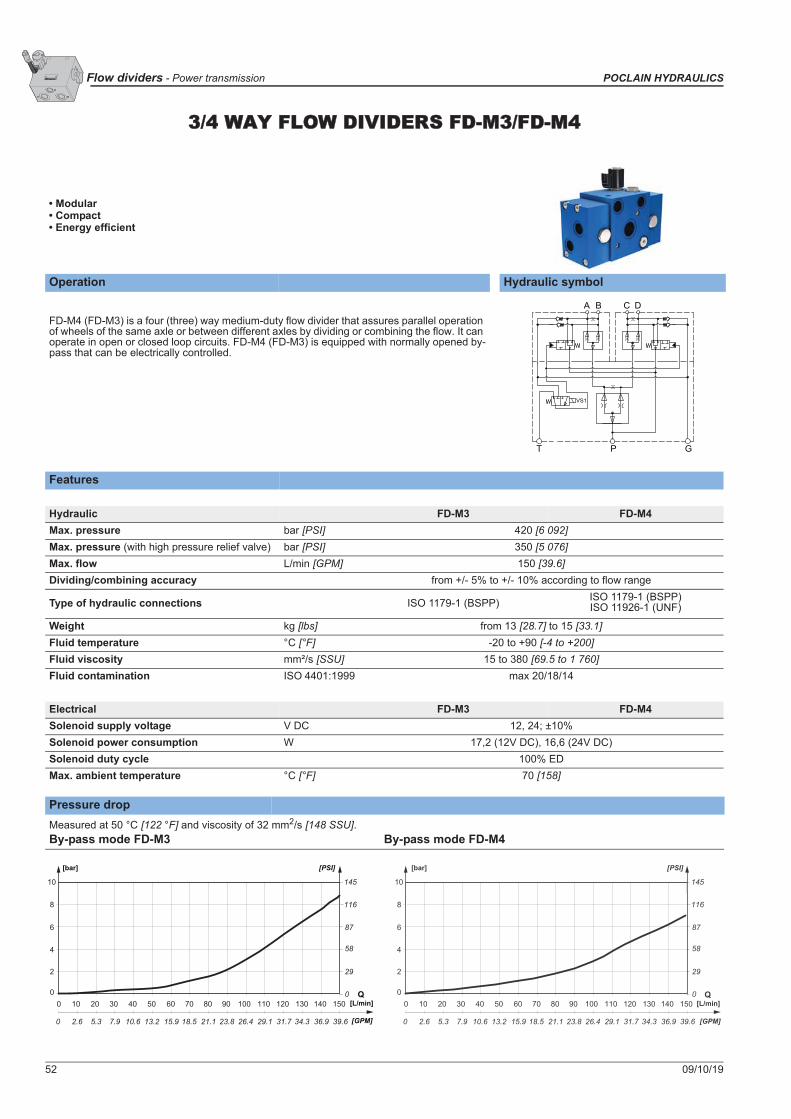
3/4 WAY FLOW DIVIDERS FD-M3/FD-M4
• Modular• Compact• Energy efficient
Operation Hydraulic symbol
FD-M4 (FD-M3) is a four (three) way medium-duty flow divider that assures parallel operation of wheels of the same axle or between different axles by dividing or combining the flow. It can operate in open or closed loop circuits. FD-M4 (FD-M3) is equipped with normally opened by-pass that can be electrically controlled.
Features
Hydraulic FD-M3 FD-M4Max. pressure bar [PSI] 420 [6 092]Max. pressure (with high pressure relief valve) bar [PSI] 350 [5 076]Max. flow L/min [GPM] 150 [39.6]Dividing/combining accuracy from +/- 5% to +/- 10% according to flow range
Type of hydraulic connections ISO 1179-1 (BSPP) ISO 1179-1 (BSPP)ISO 11926-1 (UNF)
Weight kg [lbs] from 13 [28.7] to 15 [33.1]Fluid temperature °C [°F] -20 to +90 [-4 to +200]Fluid viscosity mm²/s [SSU] 15 to 380 [69.5 to 1 760]Fluid contamination ISO 4401:1999 max 20/18/14
Electrical FD-M3 FD-M4Solenoid supply voltage V DC 12, 24; ±10%Solenoid power consumption W 17,2 (12V DC), 16,6 (24V DC)Solenoid duty cycle 100% EDMax. ambient temperature °C [°F] 70 [158]
Pressure dropMeasured at 50 °C [122 °F] and viscosity of 32 mm2/s [148 SSU].By-pass mode FD-M3 By-pass mode FD-M4
A B C D
T P G
VS1
0
2
4
6
8
0 10 20 30 40 50 60 70 80 90 100 110 120 130 140 150
58
116
29
87
0 2.6 5.3 7.9 10.6 13.2 15.9 18.5 21.1 23.8 26.4 29.1 31.7 34.3 36.9 39.6
10 145
0 Q [L/min]
[GPM]
[bar] [PSI]
0
2
4
6
8
0 10 20 30 40 50 60 70 80 90 100 110 120 130 140 150
58
116
29
87
0 2.6 5.3 7.9 10.6 13.2 15.9 18.5 21.1 23.8 26.4 29.1 31.7 34.3 36.9 39.6
10 145
0 Q[L/min]
[GPM]
[bar] [PSI]

09/10/19 53
POCLAIN HYDRAULICS Power transmission - Flow dividers
2 w
ay F
low
div
ider
FD
-M2
3/4
way
Flo
w d
ivid
ers
FD-M
3/ F
D-M
42
way
Hea
vy d
uty
Flow
div
ider
FD
-H2
Dimensions with charge check and with or without pressure relief valve
Hydraulic scheme - Electric by-pass control with charge check valve
10 [0.39]
90±0,3 [3.54±0.01]
38 [1.49]
43 [1
.69]
93 [3.66]83 [3.27]
50 [1.97]
17 [0.67]
17 [0
.67]
66,3
[2.6
1]10
3 [4
.06]
190 [7.48]
91 [3
.58]
61 [2
.40]
25
[0.9
8]
70 [2.76]182 [7.17]
80 [3
.15]
5
2±0,
3 [2
.05±
0.01
]
VS2
VS1
B
A
FP
T
G
C
4xM8 x 12/15
- -3D -MF B - -1 2 1 2 3
T
1 2
R
1 2 3 4
D
1 2 3 4
V P
1 2 3
C
1 2 3
S
A B C
T P GF
VS1
VS2
C
T P GF
VS1
VS2
A B
Without pressure relief valveWith pressure relief valve

54 09/10/19
Flow dividers - Power transmission POCLAIN HYDRAULICS
Dimensions with charge check and pressure relief valve
Hydraulic scheme - Hydraulic by-pass control with charge check and relief valves
90±0,3 [3.54±0.01]
10 [0.39]
80
[3.1
5]
52±
0,3
[2.0
5±0.
01]
70 [2.76]182 [7.17]
25 [0
.98]
61 [2
.40]
91 [3
.58]
214 [8.43]
17 [0
.67]
66,3
[2.6
1]
17 [0.67]50 [1.97]
83 [3.27]60 [2.36]
25 [0
.98]
61 [2
.40]
4xM8 x 12/15
B
A
VS2
VS1
FP
T
G
C
D
- -4D -MF B - -1 2 1 2 3
T
1 2
R
1 2 3 4
D
1 2 3 4
V P
1 2 3
C
1 2 3
S
Ø0.8
Ø0.
7
Ø0.
7
A B DC
GPFT
VS2
VS1
Designed for max. pressure 420 bar [6 092 PSI].

09/10/19 55
POCLAIN HYDRAULICS Power transmission - Flow dividers
2 w
ay F
low
div
ider
FD
-M2
3/4
way
Flo
w d
ivid
ers
FD-M
3/ F
D-M
42
way
Hea
vy d
uty
Flow
div
ider
FD
-H2
Dimensions without pressure relief valve
Hydraulic scheme - Electric by-pass control without charge check valve and without pressure relief valve
B
A
210 [8.27]
57,5
[2.2
6]28
,5[1
.12]
93 [3.66]
17[0.67]
50[1.97]
83 [3.27]
57,5
[2.2
6]
28,5
[1.1
2]
90 +0,3-0,3
[3.54 ] +0.01-0.01
10 [0.39]
80 [3
.15]
52 +0
,3-0
,3
[2.0
5
] +0
.01
-0.0
1
182,3 [7.18]
78 [7.18]
38,5[1.52]
66,3
[2.6
1]17
[0.6
7]
4x M8x12
103
[4.0
6]17
[0.6
7]
52[2.05]
91,5 [3.60]
FP
GT
C
DVS2
VS1
- -4D -MF 00 - -1 2 1 2 3
T
1 2
R
1 2 3 4
D
1 2 3 4
V P
1 2 3
C
1 2 3
S
A B C D
T P GF
VS1
VS2

56 09/10/19
Flow dividers - Power transmission POCLAIN HYDRAULICS
Hydraulic connections
FD-M3 / FD-M4
PortFunction
ConnectionMax. pressure
bar [PSI]
Min. pressure
bar [PSI]ISO 1179-1
(BSPP)ISO 11926-1
(UNF)P Main flow Inlet-Outlet G3/4 1 1/16-12 UNF-2B 420 [6 092]A
Divided flow outlet - combined flow inlet G3/8 3/4-16 UNF-2B 420 [6 092]BC
Divided flow outlet - combined flow inlet G3/8 3/4-16 UNF-2B 420 [6 092]DF Auxiliary G3/8 3/4-16 UNF-2B 50 [725]G Charge flow inlet G3/8 3/4-16 UNF-2B 50 [725] 8 [116]T Drain G3/8 3/4-16 UNF-2B 5 [73]
Installation
N.m [lb .ft]
FD-M3 / FD-M4 4xM8 10.9 36 [27]
Class (*) Type (*) As per standard DIN 912
09/10/19 57
POCLAIN HYDRAULICS Power transmission - Flow dividers
2 w
ay F
low
div
ider
FD
-M2
3/4
way
Flo
w d
ivid
ers
FD-M
3/ F
D-M
42
way
Hea
vy d
uty
Flow
div
ider
FD
-H2
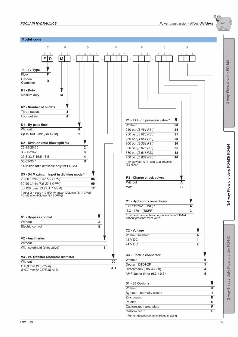
Model code
D2 - Division ratio (flow split %)25-25-25-25 230-30-20-20 333,5-33,5-16,5-16,5 433-33-33 * B* Division ratio available only for FD-M3
P3 - Charge check valvesWithout AWith B
C1 - Hydraulic connectionsISO 11926-1 (UNF) * AISO 1179-1 (BSPP) 3* Hydraulic connections only available for FD-M4 without pressure relief valve.
C3 - Electric connectorWithout 0Deutsch DT04-2P 3Hirschmann (DIN 43650) 4AMP Junior timer (6.3 x 0.8) 5
C2 - VoltageWithout solenoid A12 V DC 124 V DC 2
D3 - D4 Maximum input in dividing mode *20-60 L/min [5.3-15.9 GPM] 0630-90 L/min [7.9-23.8 GPM] 0935-120 L/min [9.2-31.7 GPM] 12* Input Q = code x10 (FD-M4 max=120L/min [31.7 GPM]; FD-M3 max=90L/min [23.8 GPM])
V2 - AuxilliariesWithout 0With solednoid (pilot valve) 1
V3 - V4 Transfer restrictor diameterWithout 00Ø 0,8 mm [0.0315 in]Ø 0,7 mm [0.0275 in] Ai-Bi AB
P1 - P2 High pressure valve *Without 00240 bar [3 481 PSI] 24250 bar [3 626 PSI] 25280 bar [4 061 PSI] 28300 bar [4 351 PSI] 30350 bar [5 076 PSI] 35380 bar [5 511 PSI] 38400 bar [5 801 PSI] 40* P between A (B) adn G at 10L/min [2.6 GPM]
R2 - Number of outletsThree outlets 3Four outlets 4
V1 - By-pass controlWithout AElectric control E
S1 - S3 OptionsWithout 0By-pass - normally closed 1Zinc coated BPainted DCustomized name plate PCustomized * F* Further description on interface drawing
D1 - By-pass flowWithout 0Up to 150 L/min [40 GPM] 1
- -D -MF - -1 2 1 2 3
T
1 2
R
1 2 3 4
D
1 2 3 4
V P
1 2 3
C
1 2 3
S
R1 - DutyMedium duty M
T1 - T2 TypeFlow FDivider/Combiner D

58 09/10/19
Flow dividers - Power transmission POCLAIN HYDRAULICS

09/10/19 59
POCLAIN HYDRAULICS Power transmission - Flow dividers
2 w
ay F
low
div
ider
FD
-M2
3/4
way
Flo
w d
ivid
ers
FD-M
3/ F
D-M
42
way
Hea
vy d
uty
Flow
div
ider
FD
-H2
22 WAY HEAVY DUTY FLOW DIVIDER FD-H2
• Modular• Compact• Energy efficient
FD-H2 with auxiliaries
Operation Hydraulic symbolFD-H2 is a two way heavy-duty flow divider that assures parallel operation of wheels of the same axle and/or between different axles by dividing or combining flow. It can be operated in open or closed loop circuits. FD-H2 is equipped with normally opened by-pass that can be controlled electrically or hydraulically.
FeaturesHydraulic FD-H2-1 FD-H2-2Max. pressure bar [PSI] 500 [7 251]Max. flow in bypass mode L/min [GPM] 200 [52.8] 300 [79.3]Max. flow in dividing/combining mode L/min [GPM] 100 [26.4] 200 [52.8]
Dividing/combining accuracy +/- 5% at 100% nominal flow+/- 7% at 50% nominal flow+/- 12% at 20% nominal flow
Type of hydraulic connections ISO 11926-1 (UNF) / ISO 1179-1 (BSPP)Weight (based on codification) kg [lbs] from 14,5 [31.9] to 19,2 [42.3]Fluid temperature °C [°F] -20 to +90 [-4 to +200]Fluid viscosity mm²/s [SSU] 9 to 500 [41.7 to 2 316]Fluid contamination ISO 4401:1999 max 20/18/14Electrical FD-H2-1 FD-H2-2Solenoid supply voltage V DC 12, 24; ±10%Solenoid power consumption W 17,2 (12V DC); 16,6 (24V DC)Solenoid duty cycle 100% EDMax. ambient temperature °C [°F] 70 [158]
Pressure drop
By-pass mode FD-H2 (up to 200L/min [52.8 GPM]) By-pass mode FD-H2 (up to 300l/min [79.3 GPM])
If you have to add a flushing valve in a closed loop circuit equipped with a flow divider, you have to install the flushing valve between the pump and the flow divider.
A B
MB
MAMP
PilGPT
VS
ØD mm
0
1
2
3
4
5
6
14.5
29
58
72.5
87
0
43.5
0
0.0
20
5.3
40
10.6
60
15.9
80
21.1
100
26.4
120
31.7
140
36.9
160
42.2
180
47.5
200
52.8
220
58.1
240
63.4
260
68.7
280
73.9
300
79.2
Q [L/min]
[GPM]
[bar] [PSI]
0
1
2
3
4
5
14.5
29
58
72.5
0
43.5
0
0.0
20
5.3
40
10.6
60
15.9
80
21.1
100
26.4
120
31.7
140
36.9
160
42.2
180
47.5
200
52.8
220
58.1
Q [L/min]
[GPM]
[bar] [PSI]
FD-H2 without auxiliaries
Measured at 50 °C [122 °F] and viscosity of 32 mm2/s [148 SSU].

60 09/10/19
Flow dividers - Power transmission POCLAIN HYDRAULICS
Hydraulic schematicElectric by-pass
Hydraulic by-pass
A B
T P G Pil
MB
MAMP
VS
ØD mm
A B
T P G Pil
MB
MAMP
VS
ØD mm
A BF2F3
VS2VS3
VS1 VS
F1 T P G Pil
MB
MAMP
A BF2F3
F1 T P G Pil
MB
MAMP
VS3 VS2
VS1 VS
ØD mm ØD mm
Without auxiliaries and with charge check valves
Without auxiliaries and with charge check valves and pressure relief valves
With auxiliaries and charge check valves With auxiliaries and with charge check valves and pressure relief valves
A B
ØD mm
VS
T P G Pil
MB
MAMP
A B
T P G Pil
MB
MAMP
VS
ØD mm
A BF2F3
VS2VS3
VS1 VS
F1 T P G Pil
MB
MAMP
ØD mm
A BF2F3
F1 T P G Pil
MB
MAMP
VS3 VS2
VS1 VS
ØD mm
Without auxiliaries and with charge check valves
Without auxiliaries and with charge check valves and pressure relief valves
With auxiliaries and charge check valves With auxiliaries and with charge check valves and pressure relief valves

09/10/19 61
POCLAIN HYDRAULICS Power transmission - Flow dividers
2 w
ay F
low
div
ider
FD
-M2
3/4
way
Flo
w d
ivid
ers
FD-M
3/ F
D-M
42
way
Hea
vy d
uty
Flow
div
ider
FD
-H2
FD-H2 Hydraulic Bypass overall dimension without auxiliaries and with charge check valve
FD-H2 Hydraulic Bypass overall dimension with auxiliaries and charge check valve
73 [2.87]45 [1.77]34 [1.34]23 [0.91]
143
[5.6
3] 80 [3
.15]
19 [0
.75]
17 [0
.67] 110 [4.33]
62 [2.44]130 [4.33]
45 [1.77]
133,3 [5.25 ]+1,5-1
+0.06-0.04
30 [1.18]
70 [2.76]
45 [1
.77]
55 [2
.17]
45 [1
.77]
55 [2
.17]
80 [3
.15]
62 [2
.44]
113
[4.4
5]23
1,5
[9.1
1]
14 [0
.55]
14 [0
.55]
113
[4.4
5] 47 [1
.85]
5x M10Ø 0,04
AA
12 m
in.
[0.4
7]
A-A
G
P
T
MP
MA
MB
VS
A
B
Pil
- -22D -HF 0H B00 - -1 2 1 2 3
T
1 2
R
1 2 3 4
D
1 2 3 4
V P
1 2 3
C
1 2 3
S
-
73 [2.87]45 [1.77]
34 [1.34] 23
[0.91]
17 [0
.67]
19 [0
.75]
80 [3
.15]
143
[5.6
3]21
4 [8
.43]
51,5 [2.03]
110 [4.33]
62 [2.44]
14 [0
.55]
62 [2
.44]
113
[4.4
5]23
0 [9
.06]
14 [0
.55]
2 [0
.08]
113
[4.4
5] 47 [1
.85]
176,
5 [6
.95]
214
[8.4
3]
51,5 [2.03]131,2 [5.17]
133,3 [5.25 ]+1,5-1
+0.06-0.04
130 [5.12]45 [1.77] 70 [2.76] 30
[1.18]
80 [3
.15]
45 [1
.77]
55 [2
.17]
45 [1
.77]
55 [2
.17]
5x M10Ø 0,04
12 m
in.
[0.4
7]
A
B
F2
F3
F1
T
P
Pil
G
MP
MA
MB
VS
VS2
VS3
VS1
A-A
AA
- -12D -HF 1H B00 - -1 2 1 2 3
T
1 2
R
1 2 3 4
D
1 2 3 4
V P
1 2 3
C
1 2 3
S
-

62 09/10/19
Flow dividers - Power transmission POCLAIN HYDRAULICS
Change on dimensions based on option
Electric by-pass
128,6 [5.06]
VS
VS1VS2
VS3
MB
MA
MP
- -2D -HF B53 - -1 2 1 2 3
T
1 2
R
1 2 3 4
D
1 2 3 4
V P
1 2 3
C
1 2 3
S
-
135,7 [5.34]
25°±5°
MP
MA
MB
VS
VS2 VS1
VS3
G
T
F1
P
Pil
Pil metalic plug
- -22D -HF E - -1 2 1 2 3
T
1 2
R
1 2 3 4
D
1 2 3 4
V P
1 2 3
C
1 2 3
S
-
With charge check and pressure relief valve

09/10/19 63
POCLAIN HYDRAULICS Power transmission - Flow dividers
2 w
ay F
low
div
ider
FD
-M2
3/4
way
Flo
w d
ivid
ers
FD-M
3/ F
D-M
42
way
Hea
vy d
uty
Flow
div
ider
FD
-H2
Change on dimensions based on option
Connector angular orientation
211,8 [8.33]85 [3.35]
60 [2.36]
80 [3
.15]
80 [3
.15] 80
[3.1
5]
136,7 [5.38] 160 [6.29]
12 m
in.
[0.4
7]
VS
MAMB
MP
P
Pil
T
G
A-AB BA
A PB
A
B-B
- -22D -HF - -1 2 1 2 3
T
1 2
R
1 2 3 4
D
1 2 3 4
V P2 3
C
1 2 3
S1
7
Pump flanged version
6-
25°±5° 25°±5°
25°±5°
90°±5°
90°±
5°
90°±5°
90°±5
°
90°±5°
MB
MA
VS1
VS2VS3VS
VS3 VS2
VS1
VS
MB
Deutsch DT04-2P Hirschmann (DIN 43650)

64 09/10/19
Flow dividers - Power transmission POCLAIN HYDRAULICS
Hydraulic connections
FD-H2-1: up to 200 L/min [52.8 GPM] in By-pass
Port Function
ConnectionsMax. pressure
bar [PSI]
Min. pressure
bar [PSI]ISO 1179-1 (BSPP)
Type N ISO 11926-1 (UNF)
P Main flow inlet-outlet G3/4 1 1/16-12 UNF-2B 500 [7 252]A
Divided flow outlet - combined flow inlet G1/2 7/8-14 UNF-2B 500 [7 252]BG Charge flow inlet G3/8 3/4-16 UNF-2B 50 [725] 12 [174]T Drain G3/8 3/4-16 UNF-2B 5 [72]PIL Pilot flow inlet (Hydraulic by-pass only) G1/4 9/16-18 UNF-2B 50 [725] 12 [174]MA Pressure measurement (A) G1/4 9/16-18 UNF-2B 500 [7 252]MB Pressure measurement (B) G1/4 9/16-18 UNF-2B 500 [7 252]MP Pressure measurement (P) G1/4 9/16-18 UNF-2B 500 [7 252]
FD-H2-2: up to 300 L/min [79.3 GPM] in By-pass
Port Function
ConnectionsMax. pressure
bar [PSI]
Min. pressure
bar [PSI]ISO 1179-1 (BSPP)
Type N ISO 11926-1 (UNF)
P Main flow inlet-outlet DN25 ISO 6162-2 DN25 ISO 6162-2 500 [7 252]A
Divided flow outlet - combined flow inlet DN19 ISO 6162-2 DN19 ISO 6162-2 500 [7 252]BG Charge flow inlet G3/8 3/4-16 UNF-2B 50 [725] 12 [174]T Drain G3/8 3/4-16 UNF-2B 5 [72]PIL Pilot flow inlet (Hydraulic by-pass only) G1/4 9/16-18 UNF-2B 50 [725] 12 [174]MA Pressure measurement (A) G1/4 9/16-18 UNF-2B 500 [7 252]MB Pressure measurement (B) G1/4 9/16-18 UNF-2B 500 [7 252]MP Pressure measurement (P) G1/4 9/16-18 UNF-2B 500 [7 252]
Installation
N.m [lb.ft]5xM10 8.8 49 [36]
Class (*)
(*) As per standard DIN 912Mounting position: Indifferent

09/10/19 65
POCLAIN HYDRAULICS Power transmission - Flow dividers
2 w
ay F
low
div
ider
FD
-M2
3/4
way
Flo
w d
ivid
ers
FD-M
3/ F
D-M
42
way
Hea
vy d
uty
Flow
div
ider
FD
-H2
Model code
D2 - Division ratio (flow split by %)50-50 A70-30 B80-20 C60-40 D P3 - Charge check valves
Without * AWith B* Not available with High pressure valve(P1 - P2).
C1 - Hydraulic connectionsISO 11926-1 (UNF) AISO 9974-1 (BSPP) 3Pump flanged version, ISO 1179-1(BSPP) * 6Pump flanged version, ISO 11926-1(UNF) * 7* Only available for Bypass up to 300 L/min[79.3 GPM].
C3 - Electric connectorWithout 0Naked wires 1Deutsch DT04-2P 3Hirschmann (DIN 43650) 4
C2 - VoltageWithout solenoid A12 V DC 124 V DC 2
D3 - D4 Maximum input in dividing mode50 L/min [13.2 GPM] 05100 L/min [26.4 GPM] 10150 L/min [39.6 GPM] * 15200 L/min [52.8 GPM] * 20* When Bypass flow is up to 300l Lmin [79.3 GPM].
V2 - AuxilliariesWithout 01 solenoid valve 12 solenoid valves 23 solenoid valves 3
V3 - V4 Transfer restrictor diameterWithout 00Ø 0,6 mm [0.024 in] 06Ø 0,8 mm [0.031 in] 08Ø 1,0 mm [0.039 in] 10Ø 1,2 mm [0.047 in] 12Ø 1,5 mm [0.059 in] 15Ø 2,0 mm [0.078 in] 20
P1 - P2 High pressure valveWithout 00380 bar [5 511 PSI] 38400 bar [5 801 PSI] 40420 bar [6 091 PSI] 42
R2 - Number of outlets2 outlets 2
V1 - By-pass controlElectric control EHydraulic control H
S1 - S3 OptionsWithout 0By-pass - normally closed 1Zinc coated BPainted DCustomized name plate PCustomized * F* Further description on interface drawing.
D1 - By-pass flowUp to 200 L/min [52.8 GPM] 1Up to 300 L/min [79.5 GPM] 2
- -2D -HF - -1 2 1 2 3
T
1 2
R
1 2 3 4
D
1 2 3 4
V P
1 2 3
C
1 2 3
S
R1 - DutyHeavy duty H
T1 - T2 TypeFlow FDivider/Combiner D
-

66 09/10/19
Flow dividers - Power transmission POCLAIN HYDRAULICS
09/10/19 67
POCLAIN HYDRAULICS Power transmission - Pressure reducing valve
CONTENT
Pres
sure
redu
cing
val
ve P
R3
2 way flow divider FD-M2 51
3/4 way flow dividers FD-M3/FD-M4 56
2 way heavy duty flow divider FD-H2 63
PRESSURE REDUCING VALVE
Pressure reducing valve PR3 69
Directional control valve VD 2V 2H20/H25 77
Directional control valves VD 3V 2H 20/25 81

68 09/10/19
Pressure reducing valve - Power transmission POCLAIN HYDRAULICS

09/10/19 69
POCLAIN HYDRAULICS Power transmission - Pressure reducing valve
Pres
sure
redu
cing
val
ve P
R3
PRESSURE REDUCING VALVE PR3
• Compact• Adjust pressure inside the system• Fix or variable pressure setting
Operation Hydraulic symbolThe PR3 is used to reduce the pressure in the motor line or in auxiliary functions.
Features
Hydraulic PR3-...-S PR3-...-VMax. operation pressure bar [PSI] 250 [3 625]Max. flow L/min [GPM] 30 [7.93]Type of setting Fix VariableSetting pressure range bar [PSI] 10 to 120 [145 to 1 740]Type of hydraulic connections ISO 1179-1 (BSPP) / ISO 9974-1 (Metric) / ISO 6149 (Metric) / ISO 11926-1 (UNF)Mass kg [lbs] 0,7 [1.54]
Hydraulic connectionsConnections
Port Function ISO 1179-1 (BSPP) ISO 11 926-1(UNF) ISO 9974-1 (Metric) Max. pressure
bar [PSI]Min. pressure
bar [PSI]P Input G 1/4 9/16-18 UNF-2B M14x1.5 250 [3 625]F Output G 1/4 9/16-18 UNF-2B M14x1.5T Tank G1/4 9/16-18 UNF-2B M14x1.5 1 [14.50]
Fix settings Variable settings
FTP F
TP F
TP
Fix settings Variable settings With check valve

70 09/10/19
Pressure reducing valve - Power transmission POCLAIN HYDRAULICS
Dimensions
Fix pressure setting Variable pressure setting
50 [1
.97]
76,5
[3.0
1]
62,5
[2.4
6]
98,7
[3.8
9]
6 [0
.24]
51,4 [2.02]
24,7 [0.97]
40 [1.57]
18,5 [0.73]
18,5 [0.73]
13,5
[0.5
3]13
,5[0
.53]
2x M6
Ø 34 [1.34 dia.]
7
[0.2
8]
Ø 34 [1.34 dia.]
S=13Mt=24±2 Nm
12,
5 [0
.49]
max
. 33,
5[m
ax. 1
.32]
S=4
V1 2
C
S1 2
C

09/10/19 71
POCLAIN HYDRAULICS Power transmission - Pressure reducing valve
Pres
sure
redu
cing
val
ve P
R3
Optional fix plate
60 [2.36]70 [2.76]
5 [0
.19]
40 [1
.57]
2x Ø6,5 [0.26 dia.]
57 ± 0,2 [2.24 ± 0.008]
6,5 [0.26]
27 ±
0,2
[1.0
6 ±
0.00
8]
Mt=10 ± 1 Nm
-2- -03 - - FR 0P1 2 3
T
1 2 3
F
1 2 3
P
4 1 2
Q
1 2
C
1 2 3
R
1 2 3
S
4

72 09/10/19
Pressure reducing valve - Power transmission POCLAIN HYDRAULICS
Model code
1
T1 - T3 TypePressure PReducer R30 L/min [7.93 GPM] 3
- 00 02- -03 -0 00-
F1 - F3 Pressure controlHydraulic 002
R3 - Hydraulic connectionsWithout 0ISO 1179-1 (BSPP) 3ISO 9974-1 (Metric) 4ISO 6149 (Metric) 8ISO 11 926-1 (UNF) A
P4 - Pressure curve shapeLinear 1 S1 - S4 Options
Without 0Specific setting or flow 1Customized component * 3Optional fix plate FCustomized name plate PPainted D* Consult your Poclain Hydraulics application engineer.
P1 - P3 Pressure settingsWithout 00010 bar [145 PSI] 00220 bar [290 PSI] 00330 bar [435 PSI] 00A40 bar [580 PSI] 00450 bar [725 PSI] 00H60 bar [870 PSI] 00580 bar [1 160 PSI] 006100 bar [1 450 PSI] 007120 bar [1 740 PSI] 008
Q1 - Q2 Check valve on flow P to FWithout 00With A0C1 - Mechanical controlsFix pressure setting SVariable pressure setting V
R 0P
C2 - Pressure controllerWithout 0
1 2 3
T
1 2 3
F
1 2 3
P
4 1 2
Q
1 2
C
1 2 3
R
1 2 3
S
4
R1 - Electric connectionWithout 0
R2 - VoltageWithout 0

09/10/19 73
POCLAIN HYDRAULICS Power transmission - Directional control valves
CONTENT
Dire
ctio
nal c
ontr
ol v
alve
VD
2V
2H20
/H25
Dire
ctio
nal c
ontr
ol v
alve
VD
3V
2H20
/H25
2 way flow divider FD-M2 51
3/4 way flow dividers FD-M3/FD-M4 56
2 way heavy duty flow divider FD-H2 63
DIRECTIONAL CONTROL VALVES
Directional control valve VD 2V 2H20/H25 75
Directional control valve VD 2V 2H20/H25 77
Directional control valves VD 3V 2H 20/25 81
Directional control valve VD 3V 2H20/H25 77

74 09/10/19
Directional control valves - Power transmission POCLAIN HYDRAULICS

09/10/19 75
POCLAIN HYDRAULICS Power transmission - Directional control valves
Dire
ctio
nal c
ontr
ol v
alve
VD
2V
2H20
/H25
Dire
ctio
nal c
ontr
ol v
alve
VD
3V
2H20
/H25
DIRECTIONAL CONTROL VALVE VD 2V 2H20/H25
Function: Two position flow directional control valve, opens or closes a circuit.
Valve VD 2V 2H20 Valve VD 2V 2H25
Commercial Description VD 2V 2H20VD 2V 2H25
Part number 003943368U (VD 2V 2H20)003943367T (VD 2V 2H25)
Compatibility All types of circuit
Hydraulic symbol
CaracteristicsMass 8 kg [17.6 lb]
Commercial descriptionPressure bar [PSI]
Flow L/min [GPM]
VD 2V 2H20450 [6 526]
92 to 170 [25 to 45]VD 2V 2H25 170 to 300 [45 to 80]
Pressure drop (1 2 or 1 3)
L/minGPM
P P
SI
P ba
r
VD 2V 2H20VD 2V 2H25

76 09/10/19
Directional control valves - Power transmission POCLAIN HYDRAULICS
VD 2V 2H 20 Dimensions
VD 2V 2H 25 Dimensions
The plug can positionned in 3
InstallationValve mounting position: IndifferentChassis mounting:
Ref. Quantity ClassN.m [lb.ft] ± 10 %
(as per standard DIN 912)
M10 4 8.8 50 [37]
Hydraulic connections:
Port FunctionConnection Max. pressure
bar [PSI]
N.m [lb.ft] ± 10 %(as per standard DIN 912)
H20 H25 H20 H25
1-2-3 HP circuit
DN 19(NF E 48 055)
SAE 6000 PSI 3/4'' (ISO DP 6162)
DN 25 (NF E 48 055)
SAE 6000 PSI 1'' (ISO DP 6162)
450 [6 526] 55 [41] 60 [44]
Z PilotM16 x 1.5
5 [75.2] + F60 [44]
F Drain 3 [45]
The pressure in F port must be added to the pressure in Z port (control).
1

09/10/19 77
POCLAIN HYDRAULICS Power transmission - Directional control valves
Dire
ctio
nal c
ontr
ol v
alve
VD
2V
2H20
/H25
Dire
ctio
nal c
ontr
ol v
alve
VD
3V
2H20
/H25
DIRECTIONAL CONTROL VALVE VD 3V 2H20/25
Function: Two position flow directional control valve, allowing to dired a circuit.
Valve VD 3V 2H 20 Valve VD 3V 2H 25
Commercial DescriptionVD 3V 2H20VD 3V 2H25
Part number 003943319R (VD 3V 2H20)003943320S (VD 3V 2H25)
Compatibility All types of circuitHydraulic symbol
CaracteristicsMass 8 kg [17.6 lb]
Commercial Description Pressure bar [PSI]
Flow L/min [GPM]
VD 3V 2H20450 [6 526]
92 to 170 [25 to 45]VD 3V 2H25 170 to 300 [45 to 80]
Pressure drop
L/minGPM
P P
SI
P ba
r
VD 3V 2H20VD 3V 2H25

78 09/10/19
Directional control valves - Power transmission POCLAIN HYDRAULICS
VD 3V 2H 20 Dimensions
VD 3V 2H 25 Dimensions
InstallationValve mounting position : IndifferentChassis mounting :
Ref. Quantity ClassN.m [lb.ft] ± 10 %
(as per standard DIN 912)
M10 4 8.8 50 [37]
Hydraulic connections:
Port FunctionConnection Max. pressure
bar [PSI]
N.m [lb.ft] ± 10 %(as per standard DIN 912)
H20 H25 H20 H25
1-2-3 HP circuit
DN 19(NF E 48 055)
SAE 6000 PSI 3/4''(ISO DP 6162)
DN 25 (NF E 48 055)
SAE 6000 PSI 1''(ISO DP 6162)
450 [6 526] 55 [41] 60 [44]
Z PilotM16 x 1.5
5 [75.2] + F60 [44]
F Drain 3 [45]
The pressure in F port must be added to the pressure in Z port (control).
1

09/10/19 79
POCLAIN HYDRAULICS Power transmission - Directional control valves
Dire
ctio
nal c
ontr
ol v
alve
VD
2V
2H20
/H25
Dire
ctio
nal c
ontr
ol v
alve
VD
3V
2H20
/H25

www.poclain-hydraulics.com
Poclain Hydraulics reserves the right to make any modifications it deems necessary to the products described in this document without prior notification.The information contained in this document must be confirmed by Poclain Hydraulics before any order issubmitted.Illustrations are not binding.The Poclain Hydraulics brand is the property of Poclain Hydraulics S.A.
B33971Z
09/10/2019