power topic #8001 | technical information from cummins ... · pdf fileas outlined in the ibc...
TRANSCRIPT

The International Code Council’s International Building Code (IBC) has become the primary code document for engineers specifying generating equipment and supervising its installation. The IBC has replaced regional codes in most jurisdictions and incorporates strong provisions regarding seismic and wind performance of electric generating sets that must be considered.
Understanding the IBC
The IBC was developed when the three previous code-writing bodies came together to create the International Code Council. The first edition was released in 2000, and a three-year revision cycle was instituted. Currently, authorities may be using either the 2000, 2003 or 2006 edition of the IBC, with one of these editions now adopted at either the state or local level in all 50 states. Recently, the State of California adopted the 2006 edition, leading the way for that edition to become a pre-eminent standard across the U.S.
The IBC addresses both the design and installation of building systems, with an emphasis on how those systems will perform in emergency situations – and continue to perform after such events. One big change for engineers specifying seismic-related equipment is that the United States is no longer divided into broad seismic zones. Instead, seismic requirements are based on U.S. Geological Survey (USGS) data for ground accelerations at specific ZIP Codes or at a specific longitude and latitude. And, not only must critical power-generating systems be designed to the same seismic-design category as the buildings in which they are located, their location within a building—whether
it’s below-ground, at grade level or on a rooftop—also must be considered. Where custom enclosures or sub-base fuel tanks are a part of the design, the entire system must be seismically certified. This is due to the fact that fuel tanks carry flammable substances and also because of the interrelationship clause in the code, which dictates that the failure of one component can not cause the failure of a secondary critical component.
The building’s purpose as designated by its Occupancy Category or Seismic Use Group (depending on the version of the code used) also plays an important role in code-defined design requirements. The Seismic Use Group is based on the Occupancy Category of the building and is defined as follows:
• Occupancy Category IV: Buildings and other structures designated as essential facilities. This could include hospitals, police stations and fire stations.
• Occupancy Category III: Buildings and other structures that represent substantial hazard to human life in the event of failure. This could include schools, theaters and jails.
• Occupancy Category II: Buildings and other structures except those listed in Occupancy Categories I, III and IV.
• Occupancy Category I: Buildings and other structures that represent a low hazard to human life in the event of failure. These include agricultural facilities, certain temporary facilities and minor storage facilities.
The primary applications for emergency power systems covered by these various Occupancy Categories are for emergency lighting and life-support systems. However,
> White paper By Aniruddha Natekar, Sales Application Engineer
Installation considerations for IBC compliant generator sets
Power topic #8001 | Technical information from Cummins Power Generation
www.cumminspower.com© 2008 Cummins Power Generation
engineers need to understand that other building systems also might be critical to a building’s operation during and after an emergency. For example, heating, ventilating and air-conditioning equipment could be essential in some healthcare settings, and so require its own code-compliant backup power systems.
Providing protection
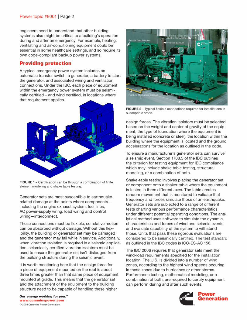
A typical emergency power system includes an automatic transfer switch, a generator, a battery to start the generator, and associated wiring and ventilation connections. Under the IBC, each piece of equipment within the emergency power system must be seismi-cally certified – and wind certified, in locations where that requirement applies.
Generator sets are most susceptible to earthquake- related damage at the points where components—including the engine exhaust system, fuel lines, AC power-supply wring, load wiring and control wiring—interconnect.
These connections must be flexible, so relative motion can be absorbed without damage. Without this flex-ibility, the building or generator set may be damaged and the generator may fail while in service. Additionally, when vibration isolation is required in a seismic applica-tion, seismically certified vibration isolators must be used to ensure the generator set isn’t dislodged from the building structure during the seismic event.
It is worth mentioning here that the design force for a piece of equipment mounted on the roof is about three times greater than that same piece of equipment mounted at grade. This means that the generator set and the attachment of the equipment to the building structure need to be capable of handling these higher
design forces. The vibration isolators must be selected based on the weight and center of gravity of the equip-ment, the type of foundation where the equipment is being installed (concrete or steel), the location within the building where the equipment is located and the ground accelerations for the location as outlined in the code.
To ensure a manufacturer’s generator sets can survive a seismic event, Section 1708.5 of the IBC outlines the criterion for testing equipment for IBC compliance which may include shake table testing, structural modeling, or a combination of both.
Shake-table testing involves placing the generator set or component onto a shaker table where the equipment is tested in three different axes. The table creates random movement that is monitored to validate that frequency and forces simulate those of an earthquake. Generator sets are subjected to a range of different tests charting various performance characteristics under different potential operating conditions. The ana-lytical method uses software to simulate the dynamic characteristics and forces of wind and seismic events and evaluate capability of the system to withstand those. Units that pass these rigorous evaluations are considered to be seismically certified. The test standard as outlined in the IBC codes is ICC-ES-AC 156.
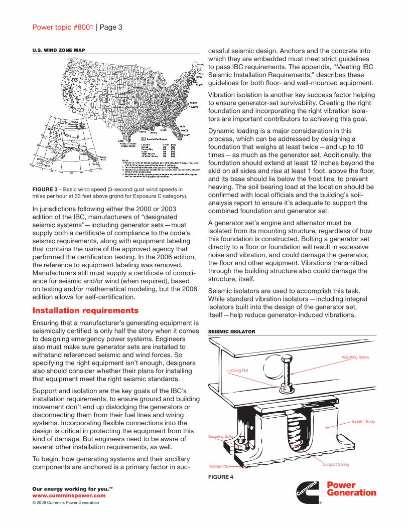
The IBC 2006 requires that generator sets meet the wind-load requirements specified for the installation location. The U.S. is divided into a number of wind zones, according to the highest wind speeds occuring in those zones due to hurricanes or other storms. Performance testing, mathematical modeling, or a combination of both, are required to certify equipment can perform during and after such events.
Power topic #8001 | Page 2
FIGURE 2 – Typical flexible connections required for installations in susceptible areas.
FIGURE 1 – Certification can be through a combination of finite element modeling and shake table testing.
Flexible Duct AdapterFlexible Exhaust
Flexible Fuel Lines
Vibration Isolation
Isolation Pad (Optional)
Fuel Line Mechanical Support
Flexible Power and Control Connections
www.cumminspower.com© 2008 Cummins Power Generation
Power topic #8001 | Page 3
cessful seismic design. Anchors and the concrete into which they are embedded must meet strict guidelines to pass IBC requirements. The appendix, “Meeting IBC Seismic Installation Requirements,” describes these guidelines for both floor- and wall-mounted equipment.
Vibration isolation is another key success factor helping to ensure generator-set survivability. Creating the right foundation and incorporating the right vibration isola-tors are important contributors to achieving this goal.
Dynamic loading is a major consideration in this process, which can be addressed by designing a foundation that weighs at least twice—and up to 10 times—as much as the generator set. Additionally, the foundation should extend at least 12 inches beyond the skid on all sides and rise at least 1 foot. above the floor, and its base should lie below the frost line, to prevent heaving. The soil bearing load at the location should be confirmed with local officials and the building’s soil-analysis report to ensure it’s adequate to support the combined foundation and generator set.
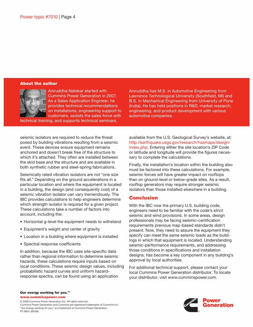
A generator set’s engine and alternator must be isolated from its mounting structure, regardless of how this foundation is constructed. Bolting a generator set directly to a floor or foundation will result in excessive noise and vibration, and could damage the generator, the floor and other equipment. Vibrations transmitted through the building structure also could damage the structure, itself.
Seismic isolators are used to accomplish this task. While standard vibration isolators—including integral isolators built into the design of the generator set, itself—help reduce generator-induced vibrations,
In jurisdictions following either the 2000 or 2003 edition of the IBC, manufacturers of “designated seismic systems”—including generator sets—must supply both a certificate of compliance to the code’s seismic requirements, along with equipment labeling that contains the name of the approved agency that performed the certification testing. In the 2006 edition, the reference to equipment labeling was removed. Manufacturers still must supply a certificate of compli-ance for seismic and/or wind (when required), based on testing and/or mathematical modeling, but the 2006 edition allows for self-certification.
Installation requirements
Ensuring that a manufacturer’s generating equipment is seismically certified is only half the story when it comes to designing emergency power systems. Engineers also must make sure generator sets are installed to withstand referenced seismic and wind forces. So specifying the right equipment isn’t enough, designers also should consider whether their plans for installing that equipment meet the right seismic standards.
Support and isolation are the key goals of the IBC’s installation requirements, to ensure ground and building movement don’t end up dislodging the generators or disconnecting them from their fuel lines and wiring systems. Incorporating flexible connections into the design is critical in protecting the equipment from this kind of damage. But engineers need to be aware of several other installation requirements, as well.
To begin, how generating systems and their ancillary components are anchored is a primary factor in suc-
FIGURE 3 – Basic wind speed (3-second gust wind speeds in miles per hour at 33 feet above grond for Exposure C category).
U.S. WIND ZONE MAP
FIGURE 4
Adjusting Screw
Isolator Body
Support SpringRubber Pad
Securing Bolts
Locking Nut
SEISMIC ISOLATOR
Power topic #7010 | Page 4
www.cumminspower.com© 2008 Cummins Power Generation Inc. All rights reserved. Cummins Power Generation and Cummins are registered trademarks of Cummins Inc. “Our energy working for you.” is a trademark of Cummins Power Generation.PT-8001 (09/08)
seismic isolators are required to reduce the threat posed by building vibrations resulting from a seismic event. These devices ensure equipment remains anchored and doesn’t break free of the structure to which it’s attached. They often are installed between the skid base and the structure and are available in both synthetic rubber and steel-spring fabrications.
Seismically rated vibration isolators are not “one size fits all.” Depending on the ground accelerations in a particular location and where the equipment is located in a building, the design (and consequently cost) of a seismic vibration isolator can vary tremendously. The IBC provides calculations to help engineers determine which strength isolator is required for a given project. These calculations take a number of factors into account, including the:
•Horizontalg-leveltheequipmentneedstowithstand
•Equipment’sweightandcenterofgravity
•Locationinabuildingwhereequipmentisinstalled
•Spectralresponsecoefficients
In addition, because the IBC uses site-specific data rather than regional information to determine seismic hazards, these calculations require inputs based on local conditions. These seismic design values, including probabilistic hazard curves and uniform hazard-response spectra, can be found using an application
available from the U.S. Geological Survey’s website, at: http://earthquake.usgs.gov/research/hazmaps/design/index.php. Entering either the site location’s ZIP Code or latitude and longitude will provide the figures neces-sary to complete the calculations.
Finally, the installation’s location within the building also must be factored into these calculations. For example, seismic forces will have greater impact on rooftops than on ground-level or below-grade sites. As a result, rooftop generators may require stronger seismic isolators than those installed elsewhere in a building.
Conclusion
With the IBC now the primary U.S. building code, engineers need to be familiar with the code’s strict seismic and wind provisions. In some areas, design professionals may be facing seismic-certification requirements previous map-based standards didn’t present. Now, they need to assure the equipment they specify can meet the same seismic loads as the build-ings in which that equipment is located. Understanding seismic-performance requirements, and addressing those conditions in specifications and installation designs, has become a key component in any building’s approval by local authorities.
For additional technical support, please contact your local Cummins Power Generation distributor. To locate your distributor, visit www.cumminspower.com.
About the author
Aniruddha Natekar started with Cummins Power Generation in 2007. As a Sales Application Engineer, he provides technical recommendations on installations, engineering support to customers, assists the sales force with
technical training, and supports technical seminars.
Aniruddha has M.S. in Automotive Engineering from LawrenceTechnologicalUniversity(Southfield,MI)andB.S. in Mechanical Engineering from University of Pune (India). He has held positions in R&D, market research, engineering, and product development with various automotive companies.

www.cumminspower.com© 2008 Cummins Power Generation
Power topic #8001 | Appendix
Meeting IBC’s seismic installation requirements
The International Building Code (IBC) provides specific guidance on how generator sets must be installed to meet the code’s seismic requirements. The following represent some of the most important points to consider when designing installations for seismic-related projects. Be sure to reference the applicable edition of the code and any manufacturer requirements to ensure your projects are in compliance.
Anchoring requirements
•Anchorsthatarepost-installedintoconcreteforusewith generator-set components must be pre-qualified for seismic applications in accordance with ACI 355.2 and documented in a report by a reputable testing agency.
•Anchorsmustbeinstalledtoanembedmentdepthasrecommended in the Note 1 of the pre-qualification test report. In jurisdictions using IBC 2000 or IBC 2003, the minimum embedment is eight times the anchor’s diameter.
•Anchorsmustbeinstalledinnormalweightconcretewith a minimum compressive strength of 4,000 psi. Concrete aggregate must comply with ASTM C33. Installation in structural lightweight concrete is not permitted unless it has been approved by the structural engineer of record.
•Anchorsmustbeinstalledtothetorquespecificationrecommended by the anchor manufacturer to obtain maximum loading.
•Anchorsmustbeinstalledinthelocationsspecifiedon the seismic installation drawing or in the IBC seismic certification report.
•Widewashersmustbeinstalledateachanchorlocation, between the anchor head and connected equipment, for tension load distribution. These wide washers must be Series W of American National Standard Type A Plan Washers ANSI B18.22.1-1965, R1975), and the nominal washer size should match the nominal diameter of specified anchors.
Slab, pad and mounting requirements
•Concretefloorslabsandhousekeepingpadsmustbe designed and reinforced with rebar in accordance with ACI 318’s requirements for seismic applications
•Housekeeping-padthicknessmustbedesignedinaccordance with Note 1 of the pre-qualification test report, or to a minimum of 1.5 times the anchor-embedment depth, whichever is larger.
•Housekeepingpadsmustbedowelledintothebuilding’s structural floor slab and designed for seismic application per ACI 318, as approved by the structural engineer of record.
•Wall-mountedequipmentmustbeinstalledtoa rebar-reinforced structural concrete wall or a seismically designed, grout-filled concrete block wall that is approved by the engineer of record to resist the added seismic loads created by the anchored components.
•Floor-mountedequipment—withorwithoutahousekeeping pad—must be installed to a rebar-reinforced, structural-concrete floor that is seismically designed and approved by the engineer of record to resist the added seismic loads created by the anchored equipment.
•Rebarinterferencemustbeconsideredwheneverequipment is anchored to a floor or wall.
•Seismic-certifiedequipmentshouldn’tbeattached to floors constructed of lightweight concrete over steel decking.
TYPICAL VIBRATION ISOLATING FOUNDATION
1/2 Inch (13 mm) Clearance Filled
with Sealer
Spring-type Vibration Isolator Anchored With Type J or L Bolts
(See Detail)
2500 PSI (173 kPa) ReinforcedConcrete Foundation
At Least 8 Inches (200 mm) of Sand or Gravel
Detail of Type J or L Bolt AnchoringFIGURE 5