power systems consulting tres amigas interconnection ... · power systems consulting tres amigas...
TRANSCRIPT

POWER SYSTEMS CONSULTING
TRES AMIGAS INTERCONNECTION
SYSTEM IMPACT STUDY: PHASE 1
Issued: December 21, 2011
Revised: January 3, 2012
Report Number: 2011-E6276-1.R00
Prepared For:
Public Service New Mexico (PNM)
Alvarado Square
Albuquerque, NM 87158
Power Systems Consulting
ABB Inc.
940 Main Campus Drive
Raleigh, NC 27606

Legal Notice
This document, prepared by ABB Inc., is an account of work sponsored by Public Service Company
of New Mexico (PNM). Neither PNM nor ABB Inc., nor any person or persons acting on behalf of
these parties: (i) makes any warranty or representation, expressed or implied, with respect to the use
of any information contained in this document, or that the use of any information, apparatus, method,
or process disclosed in this document may not infringe privately owned rights, or (ii) assumes any
liabilities with respect to the use of or for damages resulting from the use of any information,
apparatus, method, or process disclosed in this document.

- i -
Power Systems Consulting Technical Report
ABB Inc. 2011-E6276-1.R00
Title
Tres Amigas Interconnection System Impact Study: Phase 1
Dept.
Consulting
Date
12/16/2011
Pages
Author(s): Reviewed by: Approved by:
K. Timko ABB
G. Nail PNM
T. Duane PNM
D. Dickmander ABB W. Wong ABB
J. Mechenbier PNM
PNM authored were Executive Summary and Section 11
ABB authored were Sections 1-10 and 12-13
Both Companies reviewed the report
Executive Summary:
In response to a wire-to-wire interconnection request from Tres Amigas LLC (“Tres
Amigas”), a System Impact Study (“Study”) was performed based on the non-tariff System
Impact Study Agreement dated March 3, 2011. The purpose of this Study was to evaluate the
interconnection of the proposed first 750 MW stage of Tres Amigas voltage source converter
(“VSC”) HVDC station (“Project”) paralleling PNM’s existing 200 MW HVDC converter
station (“Blackwater Station”) that interconnects the Southwest Power Pool (“SPP”), and
Western Electricity Coordinating Council (“WECC”) grids together. ABB, Inc. was retained
by PNM to perform analysis with support from PNM.
Background:
The Tres Amigas Superstation is envisioned to interconnect the Electric Reliability Council of
Texas (“ERCOT”), SPP, and WECC grids employing three VSC HVDC stations. The
ultimate build out of the Tres Amigas Superstation is envisioned to have a capacity of 5,000
MW. Stage 1 of the Project, as defined for the Study, is the interconnection of a 750 MW
VSC HVDC link between the WECC and SPP grids approximately in parallel with PNM’s
Blackwater Station located near Clovis, New Mexico. The interconnection will be between
the PNM Blackwater Station and the SPP 345 kV transmission system at the Tolk generating
station (1065 MW coal plant) east of Muleshoe, Texas. Construction is scheduled to begin in
June 2012 with an expected commercial operating date in March 2015.
Figure 1 shows a high level illustration of the Project interconnection configuration.

ii
Figure 1. Project Interconnection Configuration
StudyScope:
The Study evaluated interconnecting and transferring power in and out of the Project on an
“as available” basis only using non-firm transmission capacity due to the lack of firm
available transmission capacity. Existing transmission service commitments combined with
pending transmission service requests from Blackwater in an east to west direction outstrip the
transmission capacity of the BA-Blackwater 345 kV line (“BB line”). Previous technical
analysis has identified that substantial additional voltage support facilities must be built to
accommodate transfers at the level expected with the Project even if the existing and pending
commitments are reduced to zero. Firm power transfers in the west to east direction over the
B-A – Blackwater 345 kV line are constrained by a limitation on long-term firm available
transmission capacity from Four Corners to Albuquerque arising from congestion on WECC
Path 48 (“Path 48”). New transmission to increase Path 48 capability must be constructed for
firm deliveries to Blackwater and, therefore, the Study evaluated only off-peak load
conditions to assess impacts of the Project.
Future studies will be required to identify the necessary transmission line and station additions
for utilization of the Project that exceeds the “as available” service limitations assumed in the
Study once users of Tres Amigas make firm point-to-point transmission delivery service
requests and nothing in this Study is intended to imply any right to receive transmission
service from PNM until such upgrades are defined and in-service.
The objectives for the Study are listed below:
1. Assess the short circuit capacity at the Blackwater Station to determine if there is
sufficient system strength to support operation of Tres Amigas and Blackwater
Station.
2. Analyze the reactive power and AC voltage control strategies between the Tres
Amigas and Blackwater HVDC converters.
3. Assess steady state and dynamic performance on the PNM transmission system with
the addition of Stage 1.
Consideration was given to both peak and off-peak system conditions with the Blackwater
Station in operation at rated capacity and with the Blackwater Station operating in Static Var
Compensator (“SVC”) mode.
iii
Short Circuit Capability Assessment
The results of the short circuit capability assessment determined that there is not sufficient
short circuit capability at the Blackwater Station to support the simultaneous operation of the
Project and the existing 200 MW Blackwater Station. The short circuit requirements for the
Project converters are not fully known due to the simplified positive sequence models used for
the Study. To provide enough short circuit capability to support the operation of both the
Project and Blackwater Station, the Study assumed this capacity would be provided by
synchronous condensers Tres Amigas would locate at the Project station. To maintain
acceptable dynamic system performance, the size of the synchronous condenser was
established at 250 MVA.
Steady-State Performance
The powerflow analysis shows that substantial additional voltage support will be required to
accommodate the combined total power transfer of the Project and the Blackwater Station.
The westbound power transfer from the Project and Blackwater result in a total power transfer
requirement of 950 MW on the BB line. The total current associated with this transfer
requirement remained below the conductor thermal rating (1076 MVA) but exceeds the BB
line wavetrap rating (717 MVA) and the voltage stability limit of 371 MVA identifyied in the
analysis1.
When modeling the full transfer requirement in the eastbound direction, the thermal rating of
the BB line was exceeded due to additional current requirements associated with increased
power losses and reactive flows on the BB line. The maximum transfer that could be
accomodated without exceeding the thermal limit was 925 MW. As with the westbound
direction, the maximum transfer was found to be limited to 480 MW without substantial
additional voltage support along the BB line and to no more than 717 MVA without
replacement of the BB line wavetraps. If power output from wind farms connected to the BB
line is scheduled eastbound, it is possible that from time to time the full combined capability
of the Project and Blackwater Station could be utilized. This is not specifically explored in
the analysis.
The additional voltage support requirements identified along the BB line to support the total
power transfer from west-to-east included the addition of 450 Mvar of mechanically switched
shunt capacitor (MSSC) banks at the Guadalupe 345 kV station in order to maintain stable
operation for worst case off-peak system conditions. Based on requirements for the various
system configurations examined, a maximum step size of 150 Mvar for the MSSCs is
recommended. In addition to the MSCCs, the addition of a ±250 Mvar SVC at Guadalupe is
required to meet dynamic stability performance requirements. This SVC will also compensate
for the switching of MSSC banks which would otherwise result in unacceptably large voltage
changes.
The outage of the BB line for the westbound transfers can cause 115 kV station voltages in the
Albuquerque area to rise above acceptable limits. These voltage levels can exceed equipment
limitations and could lead to insulation failure. Currently, PNM does not have automatic
1 This voltage stability limit was established by powerflow studies. Due to its length, the BB has
relatively low surge impedance loading (426 MVA). Without compensation, it cannot be loaded much
more than the surge impedance loading because angle stability cannot be maintained.

iv
voltage-controlled shunt devices in the system that could be used to limit the 115 kV voltages
near the Albuquerque area for this type of disturbance. PNM Power System Operations
protocols indicate that voltages in excess of 1.08 pu cannot be mitigated quickly enough by
operator intervention. For this reason, an automatic voltage-controlled shunt reactor at the BA
115 kV station may be required.
Dynamic Stability Performance
Dynamic stability violations were identified for off-peak system conditions. The violations
occur for a single line to ground fault with delayed clearing (breaker failure scenario) at the B-
A 345 kV station resulting in the double line outage of both BA-Rio Puerco 345 kV circuits.
This contingency is the driver for the size requirements of the 250 Mvar SVC at Guadalupe.
Even with the SVC, remedial actions are required for this contingency. The following
scenarios were considered:
1. Runback of the Tres Amigas power schedule combined with tripping the MSSC banks at
Guadalupe.
2. Tripping Tres Amigas and the Guadalupe MSSC banks
3. Tripping Tres Amigas, the Blackwater Station, and the Guadalupe MSSC banks
The results of the study indicate that either scenario 1 or 2 is sufficient to stabilize the system.
Short Circuit Analysis
Short circuit studies were conducted to determine if the existing circuit breakers, particularly
at Blackwater and BA, can handle the increased fault currents associated with the Tres
Amigas project. Based on these results, the existing circuit breakers are adequate.

v
Blackwater Facilities
The interconnection of the project will require the addition of a 345 kV three breaker ring bus
at Blackwater. The existing station consists of a single breaker for isolating the Blackwater
Station from the BB line.
Conclusion
The results presented in this report show that the Project will require several system
improvements for the “as available” transmission service scenario assumed in the Study. The
full transfer level is summarized in the table below:
The minimum system improvements to support full transfer on an “as available” basis
include:
250 MVA synchronous condenser to be located at the Project station.
3 - 150 Mvar MSSC banks to be located at the Guadalupe 345 kV station.
±250 Mvar SVC to be located at the Guadalupe 345 kV station.
Expand the Blackwater Station from a single breaker to a three breaker 345 kV ring bus
station.
Reconductor the BA-Guadalupe 345 kV line.
Replace the communication wave trap on the BB line.
The Study also identified the maximum transfer in or out of the Project absent the system
improvements identified above other than expansion of the Blackwater switchyard. These
maximum transfers are summarized in the table below:
Without System Improvements
Transfer Direction Tres Amigas (MW) Blackwater (MW) Total (MW)
East to West 377 / 480 200 577 / 680 East to West 450 / 676 off-line 450 / 676 West to East 355 / 371 200 555 / 571 West to East 450 / 550 off-line 450 / 550
The first number reflects reduced transfer levels to address apparent operational limitations of
the Project likely resulting from the lack of adequate short-circuit capacity at the Blackwater
345 kV switchyard. The limitations are implied by the behavior of the dynamic model
provided for the Project. The second number reflects voltage stability limitations of the BB
line.
Discussions with Tres-Amigas have indicated that estimates for the scenario without system
improvements are of primary interest. As a result cost estimates included in the Study are
limited to expansion of the Blackwater 345 kV station into a three breaker ring bus. The cost
estimate and schedule are summarized below:
With System Improvements
Transfer Direction Tres Amigas (MW) Blackwater (MW) Total (MW)
East to West 750 200 950 West to East 750 200 950

vi
Interconnection item Cost
Estimated
Time for construction
Expand the Blackwater Station from a single to three breakers $7 M 18 months
The results of this analysis are preliminary and may be modified based on more detailed
technical study (Phase 2) to analyze the control interactions between devices, temporary over-
voltages, coordination of control and protection, evaluation of single pole switching, low
order harmonic resonance, AC filter performance and dynamic over voltages.
The results of the Study are based on available data and assumptions made at the time of
conducting the Study. The results provided in this report may not apply if any of the data,
models and/or other assumptions used to perform the Study change.
Rev No. Revision Description Date Authored by Reviewed by Approved by
0 Initial Draft Report 12/08/2011 K. Timko
G. Nail T. Duane
D. Dickmander W. Wong
J. Mechenbier
DISTRIBUTION:
George Nail, PNM
Jeff Mechenbier, PNM
Tom Duane, PNM

vii
TABLE OF CONTENTS
1 INTRODUCTION............................................................................................................................... 1
2 PLANNED TRES AMIGAS FACILITIES – STAGE 1 .................................................................. 3
3 STUDY PROCESS.............................................................................................................................. 5
3.1 SETUP OF PSLF BASE CASES ......................................................................................................... 5 3.2 INVESTIGATION OF SHORT CIRCUIT CAPABILITY AT THE BLACKWATER STATION ......................... 6 3.3 REACTIVE POWER AND AC VOLTAGE CONTROL STRATEGIES ....................................................... 7
3.3.1 Voltage Stability Analysis .................................................................................................... 8 3.3.2 Dynamic Analysis for Small-Signal Disturbances ............................................................... 8
3.4 LARGE-SIGNAL DYNAMIC EFFECTS ON PNM SYSTEM .................................................................. 9
4 STUDY CRITERIA ...........................................................................................................................10
5 STUDY CONDITIONS AND ASSUMPTIONS ..............................................................................11
5.1 BASE CASES .................................................................................................................................11 5.2 MODELS ........................................................................................................................................21
5.2.1 Blackwater HVDC Model ...................................................................................................21 5.2.2 Tres Amigas VSC Model ....................................................................................................22 5.2.3 Tres Amigas Synchronous Condenser Model .....................................................................22 5.2.4 Guadalupe Dynamic Reactive Compensation Model ..........................................................23 5.2.5 SPS Equivalent Machine Models ........................................................................................23
6 STEADY-STATE ANALYSIS ..........................................................................................................25
7 SHORT CIRCUIT CAPABILITY ASSESSMENT ........................................................................33
8 VOLTAGE STABILITY ANALYSIS ..............................................................................................35
9 CLOSED-LOOP DYNAMIC ANALYSIS .......................................................................................37
10 DYNAMIC STABILITY ANALYSIS ..............................................................................................38
10.1 CONTINGENCIES CASE LIST ..........................................................................................................38 10.2 STABILITY RESULTS .....................................................................................................................38 10.3 REMEDIAL ACTIONS .....................................................................................................................43
10.3.1 Tres Amigas DC Power Runback .......................................................................................44 10.3.2 Tripping Tres Amigas and Guadalupe Fixed Reactive Compensation ................................47 10.3.3 Tripping Tres Amigas, Blackwater, and Guadalupe Fixed Reactive Compensation ...........47
11 PNM TRANSFER ANALYSIS WITHOUT DYNAMIC VOLTAGE SUPPORT .......................49
11.1.1 Transfer Case development .................................................................................................49 11.2 VOLTAGE STABILITY ....................................................................................................................49 11.3 STABILITY ANALYSIS ...................................................................................................................50
12 CONCLUSIONS AND RECOMMENDATIONS ...........................................................................52
13 REFERENCES ...................................................................................................................................56

1
1 Introduction
The Tres Amigas SuperStation Project (“Tres Amigas” or “Project”) is envisioned to
interconnect the Electric Reliability Council of Texas (“ERCOT”), Southwest Power Pool
(“SPP”), and Western Electricity Coordinating Council (“WECC”) grids employing three
voltage source converter (“VSC”) HVDC stations. The ultimate capacity of the project is
envisioned to have a capacity of 5,000 MW. Stage 1 of the project is the interconnection of a
750 MW VSC HVDC link between the WECC and SPP grids, in parallel with the PNM
Blackwater HVDC converter station (“Blackwater Station”) located near Clovis, New Mexico.
The proposed connection to the SPP system will be at the Tolk generating station via an
approximately 56 mile, 2-conductor bundle, 1272 kcmil single circuit 345 kV transmission line.
The connection at the Blackwater Station consists of a single circuit 22 mile transmission line of
similar design. Construction of the Tres Amigas is scheduled to begin June 2012. The expected
commercial operating date for Phase 1 is March, 2015.
Figure 1 shows a high level illustration of the Tres Amigas Phase I interconnection configuration.
Figure 1 - Tres Amigas Phase 1 Interconnection Configuration
Tres Amigas, LLC has requested a wires-to-wires interconnection with PNM. PNM entered into
a Non-Tariff Study Agreement with Tres Amigas, LLC to assess both the short circuit capability
at the Blackwater Station and the steady state and dynamic effects associated with the proposed
interconnection of the Tres Amigas project to the PNM transmission system. ABB, Inc. was
retained by PNM to perform a System Impact Study (“Study”).
The Study will evaluate delivery of power in and out of Tres Amigas beyond Blackwater Station
on an “as available” basis only using non-firm transmission capacity. For Blackwater power
transfers from east to west, existing and pending requests today outstrip the transmission
capacity of the Blackwater-BA 345 kV line (“BB line”). Based on previous technical analysis,
even if the existing commitments are reduced to zero, without additional voltage support, the
Tres Amigas’s ability to deliver power would be constrained. For Blackwater power transfers
from west to east, on the other hand, a limitation on long-term firm transmission capacity from
Four Corners to Albuquerque arising from congestion on WECC Path 48 (“Path 48”) will require

2
new transmission to be constructed for firm deliveries to Blackwater and therefore the Study will
evaluate only off-peak load conditions to assess possible impacts of the proposed interconnection
of the Tres Amigas on the PNM transmission system for Path 48.
PNM and Tres Amigas, LCC acknowledge and agree that future studies will be required once
users of Tres Amigas make firm point-to-point transmission delivery service and that nothing in
this Study will constitute an offer of transmission service or confers upon Tres Amigas any right
to receive transmission service from PNM.
Study Objectives
Based on the above information and additional information supplied by PNM in response to the
Tres Amigas’ interconnection request, the objectives of this Study for PNM were as follows:
1. Base case development
2. Assess the short circuit capability at the Blackwater Station to determine if there is
sufficient short-circuit capability to support the Tres Amigas interconnection at the
Blackwater Station.
3. Analyze the reactive power and AC voltage control strategies between the Tres Amigas
and Blackwater HVDC converters.
4. Assess steady state and dynamic effects on the PNM transmission system with the
addition of Stage 1.
5. Report
Following this Study a more detailed technical study will be performed employing a 3-phase
model to analyze all the control features at Blackwater Station, NM Wind Energy Center
wind farm, and the Argonne Mesa wind farm along with its static var compensator (referred
to as “STATCOM”). This analysis will be performed at a later date and will evaluate the
impact of the Tres Amigas Stage 1 converter with regard to control interactions between
devices, temporary over-voltages, coordination of control and protection, evaluation of single
pole switching, low order harmonic resonance and AC filter performance, and dynamic over
voltages

3
2 Planned Tres Amigas Facilities – Stage 1
Stage 1 of the Tres Amigas project involves the construction of a 750 MW VSC HVDC link
between the PNM system at Clovis, NM and the SPP system at the Tolk generating station in
Amarillo, Texas. The proposed link is in parallel with the existing Blackwater HVDC station at
Clovis. The HVDC facility consists of:
A 750 MW, 399 kV two-terminal VSC HVDC system to be supplied by Alstom Grid UK
LTD. The reactive power capability curves for the VSC converters are illustrated below in
Figure 2. Data for the transformers supplying both converter stations is shown below in Table
1.
Approximately 56 miles of 2-conductor bundle, 1272 kcmil single circuit 345 kV transmission
line for the connection to the SPP system at the Tolk generating station.
Approximately 22 miles of 2-conductor bundle, 1272 kcmil single circuit 345 kV transmission
line for the connection to the PNM Blackwater Station.
Table 1 - Converter Transformer Data
Description Station A Station B
Nominal MVA rating 825 MVA 825 MVA
Vector Group YNd11yn
Nominal Line Winding Voltage 345.0 kVrms 345.0 kVrms
Rated Valve Winding Voltage 399.0 kVrms
Valve winding voltage range: Nominal
Maximum
Minimum
399.0 kVrms
462.0 kVrms
320.0 kVrms
Transformer impedance between the line winding and valve winding
(on 825 MVA, 399kV base) 0.157 pu
Impedance tolerance 5.0%

4
Figure 2 - Reactive Power Capacity of the Converter
-600
-400
-200
0
200
400
600
800
-800 -700 -600 -500 -400 -300 -200 -100 0 100 200 300 400 500 600 700 800
Real Power (P), MW
Reac
tive
Pow
er (Q
), M
var
Nominal AC System Voltage
Minimum AC System Voltage
Maximum AC System Voltage

5
3 Study Process
The impact on the performance of the PNM transmission system of transmitting 750 MW via the
Tres Amigas interconnection was determined by conducting steady-state and dynamic stability
analyses using the process described below. The objective of this analysis was to identify
whether the transfers lead to steady state criteria violations or system instability with respect to
rotor angle and voltage stability. To this end, the following tasks have been completed:
1. Base case development
2. Short circuit capability assessment.
3. Assessment of the reactive power and AC voltage control strategies between the Tres
Amigas and Blackwater HVDC converters.
4. Steady state and dynamic assessment
The applicable WECC criteria were used to evaluate the results of this study.
3.1 Setup of PSLF Base Cases
All Phase 1 tasks use GE PSLF as the analysis tool, and therefore require PSLF power flow
models as a precondition. Starting with the pre-project base conditions modeled in the 2015
(HS) peak load and 2013-14 (HW1A) off-peak load power flow conditions provided by PNM,
system performance was analyzed for a number of normal and contingency conditions. The pre-
and post-project analysis of the Tres Amigas interconnection included the following base
conditions:
Pre-Project Analysis: 1) E-W (east to west) Operation: Blackwater at 200MW
2) W-E (west to east)Operation: Blackwater at 200 MW
3) SVC Operation: Blackwater in SVC mode (0 MW transfer)
Post-Project Analysis: 1) E-W Operation: Blackwater and Tres Amigas at 200 + 750 = 950 MW
2) E-W Operation: Without dynamic reactive voltage support
a. Blackwater 200 MW E-W
b. Blackwater off-line
3) W-E Operation: Blackwater and Tres Amigas at 200 + 750 = 950 MW
4) W-E Operation: Without dynamic reactive voltage support
a. Blackwater 200 MW
b. Blackwater off-line
5) SVC Operation:
a. Blackwater in SVC mode; Tres Amigas at 750 MW, E-W
b. Blackwater in SVC mode; Tres Amigas at 750 MW, W-E
E-W power flow cases were based on PNM 2015 peak system conditions while W-E cases were
based on the PNM 2013-14 off-peak system conditions, due in large part to the transmission
capacity limitations arising from congestion on Path 48. Existing firm transmission

6
commitments on the PNM’s transmission system were reduced to analyze the power delivery
capability (power in or out) of Tres Amigas up to 750 MW. All powerflow cases were
developed with input from PNM regarding load and generation dispatch. Furthermore, in order
to accommodate the high transfer levels on the BB line anticipated with the Tres Amigas project
and to maintain acceptable system performance2 at the 750 MW transfer level, additional fixed
and/or dynamic reactive compensation was modeled at the Guadalupe 345 kV station, along with
a synchronous condenser at Tres Amigas 345 kV station. Post project cases without the reactive
compensation at the Guadalupe 345 kV station and the synchronous condenser at Tres Amigas
were analyzed to determine the Tres Amigas maximum transfer capability without system
improvements.
It should also be noted that since the Tres Amigas HVDC will interconnect with the SPP system
at the Tolk generating station, an equivalent model of the Southwestern Public Service Company
(SPS) transmission system in the Texas panhandle was integrated into power flow models
provided by PNM. The equivalent provided by SPS was intended to improve the accuracy of the
PNM-side study by including the impedance between the SPS Blackwater and Tres Amigas
stations. No effort was made in this study to assess the impact of the Tres Amigas addition on
the SPS network. SPS will be investigating these aspects separately.
3.2 Investigation of Short Circuit Capability at the Blackwater Station
When a VSC HVDC transmission is operated in grid-parallel mode, i.e., the converters are
connected via ac transmission to a high-inertia ac network, an inner-loop current control strategy
is typically used. This strategy requires that the ac system at the point of interconnection has
sufficient strength (sufficient short circuit capacity) to ensure stable operation of the VSC. In
other words, for grid-parallel operation of the Tres Amigas VSC HVDC converters, the Tres
Amigas project will require a minimum short circuit strength at the Blackwater 345 kV station.
The Blackwater HVDC, on the other hand, also has certain short circuit requirements. Line-
commutated, thyristor-based HVDC technology requires the presence of a synchronizing voltage
of sufficient strength (short-circuit capacity) for commutation. As a rule of thumb, conventional
HVDC converters typically will require a short-circuit strength of at least 2 to 3 times the MW
rating of the HVDC line in order to operate reliably. This comparison is captured in a quantity
called the Short Circuit Ratio, SCR, as follows:
HVDC
SC
MW
MVASCR
For example, a 1000 MW HVDC system connected to an ac bus with a short circuit capacity of
2500 MVA would have an SCR of 2500/1000 = 2.5. The minimum SCR for conventional
HVDC converters is generally considered to be 2 to 3.
Line-commutated converters also consume significant amounts of reactive power in the
conversion process. For this reason, shunt capacitor and ac filter banks are required on the ac
2 The powerflow and stability performance criteria provided by PNM are given in Section 4 below.

7
bus at the converter, effectively increasing the fundamental frequency driving point impedance
of the ac network. This effect is captured in a refinement of the above equation, yielding the
Effective Short Circuit Ratio (ESCR) as follows:
HVDC
bankscapSC
MW
MVARMVAESCR
For example, adding 625 MVAR of filter and shunt capacitor banks to the system described
above yields an ESCR of (2500-625)/1000 = 1.9, which is very low. Present design guidance for
conventional HVDC is to avoid situations where the ESCR is less than 2.0.
The results of the short circuit capability assessment were therefore intended to evaluate the need
for additional short-circuit capacity at the Blackwater station in order to support the parallel
operation of the Tres Amigas 750 MW and Blackwater 200 MW HVDC interconnections. The
short circuit functionality of PSLF was used in combination with the power flow base cases
provided by PNM to evaluate the three-phase short circuit levels at the Blackwater 345 kV bus
for critical system conditions. Where short circuit machine data, Xd’’, was unavailable via the
power flow base case or the PSLF dynamics database, typical values of Xd’’ based on machine
ratings were used. The results of this task provide an indication as to which system conditions
may not meet the short-circuit requirements for both Blackwater and Tres Amigas, and will
therefore require supplementary synchronous generation and/or synchronous condensers.
3.3 Reactive Power and AC Voltage Control Strategies
The Blackwater HVDC incorporates sophisticated control functions that balance reactive power
and control of the Blackwater 345 kV ac voltage by careful coordination of ac filter and reactor
bank switching, tap changer operation, and converter firing angle calculation. Parallel operation
of the Blackwater and Tres Amigas converters was therefore analyzed to ensure an appropriate
overall strategy for reactive power and ac voltage control, and to identify the potential for control
interactions between the converters.
In conjunction with the recent Blackwater HVDC Upgrade project, ABB has developed a highly
detailed model of the Blackwater HVDC system and its controls for use in PSLF. The user
defined models include representations of the following control features:
Filter bank switching and tap changer operation: Emulated in powerflow solution model.
Closed-loop ac voltage controls, firing angle calculations: Simulated in dynamics model.
The fast-acting closed loop controls that affect firing angle calculation are fully represented in
the dynamics model. The powerflow model emulates the effect of the slower-acting filter bank
and tap changer control loops to establish a steady-state voltage reference for Blackwater.
The Blackwater PSLF model described above is assumed to be a reasonable starting point for
assessment of the impact of the Tres Amigas addition, i.e.

8
1) Shunt compensation requirements to support the additional power flow on the BB line
2) Steady-state voltage stability of the combined Blackwater / Tres Amigas system
3) Closed-loop dynamic voltage stability of the combined Blackwater / Tres Amigas system
To address the first two effects above, Q-V analysis was used to analyze the BB line injections.
This line has relatively high series impedance and shunt admittance and these characteristics play
a significant role in the overall performance of the system. For item 3 above, dynamic
simulation of the combined Blackwater/Tres Amigas system was used for the evaluation.
3.3.1 Voltage Stability Analysis
Items 1 and 2 listed above can be evaluated by using Q-V analysis for voltage stability. Q-V
analysis is used to determine the amount of reactive power required to hold a given voltage at a
given bus, with consideration given to contingencies. Each point on the Q-V curve is a separate
powerflow solution. The presence of reactive power reserves is indicated by a curve that goes
below zero, and the amount of the reserves for a given bus voltage is the distance from the zero
Q axis to the Q-V curve at that bus voltage. The Q-V curve is also useful in identifying systems
near voltage collapse, as its shape becomes flat (low dQ/dV) at the voltage stability limit. Stable
system performance is indicated when the Q-V curve has positive slope (positive dQ/dV).
Unstable system performance is identified when the Q-V curve has negative slope (negative
dQ/dV). The point where the Q-V curve flattens out and reaches a minimum value is an area of
voltage instability. For example, as the curve flattens, it only takes a small change in reactive
power to result in a large change in voltage. At the minimum point, an increase in reactive
power could either increase or decrease the voltage.
In addition to identifying the stability limit, the bottom of the Q-V curve defines the minimum
reactive power requirement for stable operation. When the minimum point on the Q-V curve is
above the zero Q axis, the powerflow case will not solve without additional reactive
compensation. In this event, the minimum point indicates how much compensation is needed at
the designated bus in order to maintain the voltage at that minimum point. Without additional
compensation, the voltage will collapse which is indicated by powerflow cases that do not solve.
For the present study, Q-V analysis was performed at the anticipated point of the minimum
system voltage during high transfers via the Blackwater and Tres Amigas interconnections, in
other words, at the Guadalupe 345 kV station. The Q-V analysis was performed in PSLF using
powerflow analysis methods and the power flow cases established in Task 1 above.
3.3.2 Dynamic Analysis for Small-Signal Disturbances
To address the closed-loop dynamic voltage stability of the combined Blackwater/Tres Amigas
system, dynamic simulations of the following scenarios were performed:
1) Blackwater and Tres Amigas at 200+750 = 950 MW, E-W:
- Switch MSSC at Blackwater
- Switch shunt reactor at Guadalupe
2) Blackwater and Tres Amigas at 200+750 = 950 MW, W-E:
- Switch MSSC at Blackwater

9
- Switch shunt reactor at Guadalupe
3) Blackwater in SVC mode; Tres Amigas at 750 MW, E-W:
- Switch MSSC at Blackwater
- Switch shunt reactor at Guadalupe
4) Blackwater in SVC mode; Tres Amigas at 750 MW, W-E:
- Switch MSSC at Blackwater
- Switch shunt reactor at Guadalupe
The dynamic analysis for the small-signal disturbance conditions described above was performed
in PSLF using the Blackwater HVDC user-defined dynamics model, the Tres Amigas HVDC
dynamics model provided by Tres Amigas, and the base power flow conditions established
above in Task 1. The generic vwscc model in PSLF was used to represent the assumed SVC at
Guadalupe 345 kV station.
3.4 Large-Signal Dynamic Effects on PNM System
The purpose of the large-signal dynamic analysis was to assess the impact of the proposed Tres
Amigas interconnection on the PNM transmission system for selected large-signal contingency
scenarios and conditions. Using positive sequence analysis methods, the overall performance of
the system was evaluated in terms of the following:
Disturbances to PNM system voltage profile
Rotor-angle stability of PNM system
Voltage stability of PNM system
The steady-state conditions established previously in Task 1 were used as the initial conditions
for dynamic simulations of the N-1 and N-2 contingencies specified by PNM. PSAS scripts
were used for both case automation and result presentation, including the identification of
voltage and branch loading violations due to the Project. Plots for the dynamic cases are
provided as appendices to this study report.
It should be noted that this assessment is to be considered only an approximate investigation of
possible impact of the proposed Tres Amigas interconnection. It is recognized that future studies
will be required if Tres Amigas or others seek to obtain firm point-to-point delivery service.

10
4 Study Criteria
Powerflow and stability performance criteria provided by PNM are given below in Table 2 and
in the paragraphs to follow.
Table 2 - Power Flow Performance Criteria
Area Conditions Load Limits Voltage (pu) Voltage
Drop Application
EPEC (Area 11)
Normal < Normal Rating
0.95 - 1.05 69kV and above
0.95 - 1.10 Artesia 345 kV
0.95 - 1.08 Arroyo 345 kV PST source side
0.90 - 1.05 Alamo, Sierra Blanca and Van Horn 69kV
Contingency < Emergency Rating
0.925 - 1.05 7% 60 kV to 115 kV
0.95 - 1.07 7% Artesia 345kV
0.95 - 1.08 7% Arroyo 345kV PST source side
0.90 - 1.05 Alamo, Sierra Blanca and Van Horn 69kV
0.95 - 1.05 7% Hidalgo, Luna, or other 345 kV buses
PNM
(Area 10)
Normal ALIS < Normal Rating 0.95-1.05 46 kV and above*
Contingency N-1 < Emergency Rating
0.925-1.08*** 6%** 46 kV to 115 kV
0.90 – 1.08*** 6%** 230 kV and above
Contingency N-2 < Emergency Rating 0.90-1.08*** 10% 46 kV and above*
Tri- State (zones
120-123)
Normal ALIS < Normal Rating 0.95-1.05 All buses
Contingency N-1 < Emergency Rating
0.90-1.1 6%** 69 kV and above except Northeastern NM and Southern NM
0.90-1.1 7%** 69 kV and above in Northeastern NM and
Southern NM
Contingency N-2 < Emergency Rating 0.90-1.1 10% All buses
*Taiban Mesa and Guadalupe 345 kV voltage 0.95 and 1.1 p.u. under normal and contingency conditions. **Tri-State Voltage Criteria, April 2008 – Correspondence to TSS. *** Provided operator action can be utilized to adjust voltages back down to 1.05
All equipment loadings must be below their normal ratings under normal conditions.
All line loadings must be below their emergency ratings for both single and double
contingencies. All transformers and equipment with emergency rating should be below their
emergency rating.
Following fault clearing for single contingencies, voltage on load buses may not dip more than
25% of the pre-fault voltage or dip more than 20% of the pre-fault voltage for more than 20
cycles. For double contingencies, voltage on load buses may not dip more than 30% of the pre-
fault voltage or dip more than 20% of the pre-fault voltage for more than 40 cycles.
Voltage stability criteria requires: “The most reactive deficient bus must have adequate reactive
power margin for the worst single contingency to satisfy either of the following conditions for
n-i outages, whichever is worse: (i) a 5% increase beyond maximum forecasted loads or (ii) a 5%
increase beyond maximum allowable interface flows. The worst single contingency is one that
causes the largest decrease in the reactive power margin.” For double contingencies (i.e., breaker
failures) the reactive margin requirement is reduced to an increase of 2.5%% beyond maximum
load or flows.

11
5 Study Conditions and Assumptions
5.1 Base Cases
Table 3 below summarizes the eight base power flow cases developed as part of this
investigation. As noted in the table, all E-W power flow cases are based on the PNM 2015
Heavy Summer peak case, while W-E cases are based on the PNM 2013-14 HW1A off-peak
case.
Table 3 - Powerflow Base Conditions
Case Direction
Blackwater
Schedule
(MW)
Tres
Amigas
Schedule
(MW)
Description
2015 Peak East-to-West
200 0 Pre-project
0 0 Pre-project; Blackwater in SVC mode
200 750 Post-project
0 750 Post-project; Blackwater in SVC mode
2013-14 Off-peak West-to-East
200 0 Pre-project
0 0 Pre-project; Blackwater in SVC mode
200 750 Post-project
0 750 Post-project; Blackwater in SVC mode
Figures 3 through 10 below illustrate the base power flow conditions developed for this study.
Figure 11 illustrates the equivalent model of the SPS transmission system in the Texas panhandle
integrated into the power flow models provided by PNM.

12
Figure 3 - Peak East-to-West; Blackwater at 200 MW (Pre-project)

13
Figure 4 - Peak East-to-West; Blackwater in SVC mode (Pre-project)

14
Figure 5 - Peak East-to-West; Blackwater at 200 MW, Tres Amigas at 750 MW

15
Figure 6 - Peak East-to-West; Blackwater in SVC mode, Tres Amigas at 750 MW

16
Figure 7 - Off-peak West-to-East; Blackwater at 200 MW (Pre-project)

17
Figure 8 - Off-peak West-to-East; Blackwater in SVC mode (Pre-project)

18
Figure 9 - Off-peak West-to-East; Blackwater at 200 MW, Tres Amigas at 750 MW

19
Figure 10 - Off-peak West-to-East; Blackwater in SVC mode, Tres Amigas at 750 MW

20
Figure 11 - SPS System Equivalent

21
As noted previously, all full transfer cases with the Tres Amigas HVDC system modeled at
750 MW include additional reactive compensation at the Guadalupe 345 kV station. Table 4
below summarizes the combinations of switched and dynamic reactive compensation modeled at
Guadalupe for each of the system configurations listed in Table 3. The level of static reactive
compensation required for each base case was based on the results of the steady-state analysis
presented in Section 6 below. Dynamic reactive compensation was sized based on the results of
the dynamic stability assessment presented in Section 10. Specifically, the N-2 breaker failure
contingency at the B-A 345 kV station was the dimensioning case for the ±250 MVAr SVC
listed in Table 4
Table 4 Guadalupe 345 kV Reactive Compensation
Case Direction
Blackwater
Schedule
(MW)
Tres
Amigas
Schedule
(MW)
Guadalupe Reactive Compensation
Static
(MVAr)
Dynamic
(MVAr)
2015 Heavy
Summer East-to-West
200 0 0 0
0 0 0 0
200 750 350 ±250
0 750 150 ±250
2013-14 HW1A
Off-peak West-to-East
200 0 0 0
0 0 0 0
200 750 450 ±250
0 750 200 ±250
5.2 Models
5.2.1 Blackwater HVDC Model
The PSLF powerflow and stability models for the 200 MW back-to-back Blackwater HVDC
system is fully documented in reports [1] and [2]. The model includes the following control
functions:
Measurements
DC Bus Voltage Processing and Constant Power Control
Current Control
o AC Voltage Dependent Current Order Limiter
o Current Control Amplifier
o SVC Regulator
Voltage Control
o Overvoltage Limiter
o AC Voltage Regulator
o Voltage Regulator
Firing Control

22
The following functions are not included in the PSLF dynamics model:
2nd harmonic damping
Single phase auto reclosure detection
5.2.2 Tres Amigas VSC Model
The PSLF stability model for the 750 MW, 399 kV Tres Amigas VSC HVDC system to be
supplied by Alstom Grid UK LTD is documented in [3].
5.2.3 Tres Amigas Synchronous Condenser Model
In anticipation of the additional short circuit capacity that will be required at the Blackwater/Tres
Amigas 345 kV station for operation of the Tres Amigas HVDC system at 750 MW, a 250 MVA
synchronous condenser was modeled at the Tres Amigas 345 kV station via a 13.8/345 kV, 7%
GSU transformer. The machine model is set to regulate the 345 kV voltage in both the
powerflow and dynamic simulations. The following synchronous condenser parameters were
modeled in the PSLF dynamic simulations:
Table 5 - Blackwater/Tres Amigas Synchronous Condenser Model
Parameter Value Parameter Value
Machine Model: genrou Exciter: esac8b
MVA 250.0 Tr 0.00
Tpdo 12.350 Kpr 200.00
Tppdo 0.058 Kir 5.00
Tpqo 0.188 Kdr 10.00
Tppqo 0.188 Tdr 0.10
H 4.000 Vrmax 35.00
D 0.000 Vrmin 0.00
Ld 2.476 Ka 10.00
Lq 1.180 Ta 0.00
Lpd 0.385 Te 1.20
Lpq 1.180 Vfemax 0.00
Lppd 0.257 Vemin 0.00
L1 0.146 Ke 1.00
S1 0.180 Kc 0.55
S12 0.708 Kd 1.10
Ra 0.0024 e1 6.50
rcomp 0.000 se1 0.30
xcomp 0.000 e2 9.00
accel 0.500 se2 3.00
Vtmult 0.00
Spdmlt 0.00
The parameters chosen for the machine and excitation system models used in the study are based
on typical synchronous condenser parameters from [4]. The size of the unit is to be determined
during the course of the study.

23
5.2.4 Guadalupe Dynamic Reactive Compensation Model
An additional ±250 MVar of dynamic reactive compensation was modeled at the Guadalupe
345 kV station in order to accommodate the higher transfer levels on the BB line anticipated with
the Tres Amigas project. The dynamic compensation was modeled in this study as a static var
compensator (“SVC”) using the PSLF vwscc model. As noted previously, the size of this SVC is
based on the results of the dynamic stability assessment and will be discussed in more detail in
Section 10. The parameters selected for the model are listed below in Table 6.
Table 6 - Guadalupe SVC Model
Parameter Value
SVC Model: vwscc
Ts1 0.00
Vemax 99.00
Ts2 0.00
Ts3 0.30
a 1.00
b 1.00
Ts4 0.00
Ts5 0.00
Ksvs 300.00
Ksd 0.00
Bmax 2.50
Bpmax 2.50
Bpmin -2.50
Bmin -2.50
Ts6 0.000
Dv 99.00
Xc 0.00
Tc 0.00
Td1 0.00
5.2.5 SPS Equivalent Machine Models
Machine data for all machines represented in the SPS equivalent are listed below in Table 7.
Each machine was represented as a voltage source behind the machine subtransient reactance
using the static classical user model, epcgencls. The machine reactances listed below are in per
unit on the assumed machine base. The GSU reactances were supplied in per unit on a 100
MVA base.
Table 7 - SPS Equivalent Machine Models
Machine kV ID
Machine
Base
(MVA)
Xd’’
(pu)
GSU
Base
(MVA)
XGSU
(pu)
XSRC
(pu)
511541 SWEETWT6 230 2 200.00 0.160 100.0 0.062 0.1420
523097 HITCHLAN 345 1 490.00 0.250 100.0 0.034 0.0850
523978 HARR BUS 230 1 1030.00 0.280 100.0 0.029 0.0562
524044 NICHOLS 230 1 400.00 0.230 100.0 0.047 0.1045
525481 PLANT X 230 1 441.00 0.230 100.0 0.045 0.0972
525543 TOLK_6 230 1 1600.00 0.310 100.0 0.025 0.0440
525830 TUCO 230 230 1 168.00 0.180 100.0 0.074 0.1811
526337 JONES 6 230 1 700.00 0.290 100.0 0.025 0.0664

24
Machine kV ID
Machine
Base
(MVA)
Xd’’
(pu)
GSU
Base
(MVA)
XGSU
(pu)
XSRC
(pu)
527849 LEA CO 2 230 1 500.00 0.250 100.0 0.055 0.1050
527865 CUNNHAM 230 1 450.00 0.250 100.0 0.079 0.1346
511456 O.K.U.-7 345 1 100.00 0.120 100.0 0.082 0.2020
Based on the PGEN values supplied for the machines modeled on the SWEETWT6 and
YOAKUM 230 kV stations, and on the NOBLE 345 kV station, an SVC model was used to
represent these machines in the dynamic simulations. Data for the vwscc SVC model used is
listed below in Table 8.
Table 8 - SPS SVC Models
Parameter Value
SVC Model: vwscc
Ts1 0.00
Vemax 99.00
Ts2 0.00
Ts3 0.20
a 1.00
b 1.00
Ts4 0.00
Ts5 0.00
Ksvs 300.00
Ksd 0.00
Bmax 9.00
Bpmax 9.00
Bpmin -9.00
Bmin -9.00
Ts6 0.000
Dv 99.00
Xc 0.00
Tc 0.00
Td1 0.00

25
6 Steady-State Analysis
Table 9 summarizes transmission facilities overloaded as a result of the Tres Amigas addition.
Note that transmission facilities that are overloaded in the original pre-project base cases are not
included in the table below. Table 10 through Table 13 summarize steady-state voltage
violations in the post-project base cases, both with and without contingencies. Post-contingency
voltage violations were determined with TCUL transformers locked and only generators and
continuously-controlled shunt banks, i.e., SVCs, regulating.
For operation of the Tres Amigas HVDC transmission facility at 750 MW, loadings on the
Taiban Mesa-Blackwater 345 kV circuit exceed the 753 MVA normal/emergency ratings for all
base conditions with the exception of the 2015 peak case with Blackwater operating in SVC
mode. However, it should be noted that the 753 MVA rating is a wave trap limitation. Once this
limitation is removed, the circuit rating will be 1076 MVA. Pre-contingency voltage violations,
comparing post-project voltages with Tres Amigas operating at 750 MW to pre-project
conditions, include the Ojo and Taos 345 kV stations in the peak cases, and the HLWR_1 and
Duran 115.00 kV stations, and the Torrance 115.00 kV and 34.5 kV buses in the off-peak cases.
The remaining pre-contingency voltage violations noted in the tables below were also found to
be violations in the original pre-project base cases.
With the exception of the Alamo 69 kV station, which is flagged as a voltage violation in both
the pre- and post-project systems for both peak and off-peak conditions, there are no additional
post-contingency voltage violations for peak conditions with east-to-west transfers on both
Blackwater and Tres Amigas. For off-peak conditions, however, with Blackwater and Tres
Amigas operating at a combined west-to-east loading of 950 MW, voltage stability issues are
evident for N-2 contingencies involving outages of the two BA-Rio Puerco 345 kV circuits. The
powerflow case for this contingency would not solve under these conditions, due to a voltage
collapse. For an outage of a single San Juan-Rio Puerco 345 kV circuit, the powerflow case
converges but violations of the 6% N-1 voltage drop criteria are evident at numerous area 10 and
zone 121 buses. With Blackwater operating in SVC mode for a total west-to-east transfer of
750 MW, the outage of both BA-Rio Puerco 345 kV circuits solves but voltage violations exceed
the N-2 10% voltage drop criteria at a number of area 10 and zone 121 buses. A preliminary
investigation appears to indicate that additional reactive compensation at the B-A 115 kV bus
may be an effective means of remedying voltage issues brought on as a result of this outage.
Outages on the BB line under heavy west-to-east conditions cause a voltage rise that would
benefit from additional reactive compensation in this area. Further investigation will be needed
to determine what mitigations are will be needed to operate with criteria.
In the off-peak west-to-east transfer case, if the Aragonne Mesa and NM Wind Energy Center
wind farms are off-line, the BA–Guadalupe 345 kV line becomes overloaded due to transmission
losses and the reactive power requirements of the line. In this operating scenario, the project was
reduced to 725 MW west-to-east transfers, which allowed the line to be operated at its rated
limit. To operate the project at the full output, the BA-Guadalupe 345 kV line would have to be
reconductored because of the high intermittency of the wind farms.

26
Table 9 - Overloaded Transmission Facilities
From To ID Loading Rating
(MW)
Loading
(%) MW MVAr MVA
2015 Peak East-to-West Transfers; Blackwater at 200 MW; Tres Amigas at 750 MW
BLACKWTR 345 kV TAIBANMS 345 kV 1 949.2 102.2 954.7 753.01 120.9
2015 Peak East-to-West Transfers; Blackwater in SVC Mode; Tres Amigas at 750 MW
None
2013-2014 Off-Peak West-to-East Transfers; Blackwater at 200 MW; Tres Amigas at 750 MW
BLACKWTR 345 kV TAIBANMS 345 kV 1 -969.1 333.2 1024.8 753.0 131.6
2013-2014 Off-Peak West-to-East Transfers; Blackwater in SVC Mode; Tres Amigas at 750 MW
BLACKWTR 345 kV TAIBANMS 345 kV 1 -769.2 155.6 784.8 753.0 100.4
1. The 753 MVA rating for the Blackwater-Taiban Mesa 345 kV circuit is a wave trap limitation. When removed,
the circuit rating will be 1076 MVA.

27
Table 10 - Steady-State Voltage Violations 2015 Peak East-to-West Transfers; Blackwater at 200 MW; Tres
Amigas at 750 MW
Bus Area/Zone Voltage
(pu)
Voltage
Drop
(%)
Notes
Post-Project, Pre-Contingency Voltage Violations1
ALAMO 69.00 kV 11 1.1050 -0.0544 Violation in Pre-project Case
OJO 345.00 kV 10 1.0594 1.5182 Voltage exceeds 1.05 pu voltage criteria
ARGONNE4 138.00 kV 10 1.0599 -1.7048 Violation in Pre-project Case
ARGONNE3 138.00 kV 10 1.0639 -1.7112 Violation in Pre-project Case
TAOS 345.00 kV 121 1.0617 1.5837 Voltage exceeds 1.05 pu voltage criteria
CINIZA 13.80 kV 122 0.9256 0.0508 Violation in Pre-project Case
Post-Contingency N-1 Voltage Violations: FOURCORN-WESTMESA 345.00 1 Outage
ALAMO 69.00 kV 11 1.1039 -0.1178 Violation in Pre-contingency Case
Post-Contingency N-1 Voltage Violations: SAN_JUAN-RIOPUERC 345.00 1 Outage
ALAMO 69.00 kV 11 1.1040 -0.1002 Violation in Pre-contingency Case
Post-Contingency N-1 Voltage Violations: B-A-NORTON 345.00 1 Outage
ALAMO 69.00 kV 11 1.1048 -0.0186 Violation in Pre-contingency Case
Post-Contingency N-1 Voltage Violations: RIOPUERC-WESTMESA 345.00 1 Outage
ALAMO 69.00 kV 11 1.1040 -0.1063 Violation in Pre-contingency Case
Post-Contingency N-1 Voltage Violations: RIOPUERC-BA 345.00 2 Outage
ALAMO 69.00 kV 11 1.1049 -0.0086 Violation in Pre-contingency Case
Post-Contingency N-1 Voltage Violations: WESTMESA-ARR___PS 345.00 1 Outage
ALAMO 69.00 kV 11 1.1006 -0.4419 Violation in Pre-contingency Case
Post-Contingency N-1 Voltage Violations: B-A 345.00/115.00 1 Outage
ALAMO 69.00 kV 11 1.1047 -0.0365 Violation in Pre-contingency Case
Post-Contingency N-2 Voltage Violations: RIOPUERC-BA 345.00 1 Outage
RIOPUERC-BA 345.00 2 Outage
ALAMO 69.00 kV 11 1.1048 -0.0233 Violation in Pre-contingency Case
Post-Contingency N-2 Voltage Violations: B-A 345.00/115.00 1 Outage
RIOPUERC-BA 345.00 2 Outage
ALAMO 69.00 kV 11 1.1045 -0.0511 Violation in Pre-contingency Case
Post-Contingency N-2 Voltage Violations: WESTMESA-SANDIA 345.00 1 Outage
WESTMESA 345.00/115.00 1 Outage
ALAMO 69.00 kV 11 1.1048 -0.0260 Violation in Pre-contingency Case
1. Pre-contingency voltage violations compare post-project voltages for base conditions with Tres Amigas operating
at 750 MW to the corresponding pre-project voltages.

28
Table 11 -Steady-State Voltage Violations 2015 Peak East-to-West Transfers; Blackwater in SVC Mode; Tres
Amigas at 750 MW
Bus Area/Zone Voltage
(pu)
Voltage
Drop
(%)
Notes
Post-Project, Pre-Contingency Voltage Violations1
ALAMO 69.00 kV 11 1.1053 0.0022 Violation in Pre-project Case
OJO 345.00 kV 10 1.0562 1.8159 Voltage exceeds 1.05 pu voltage criteria
ARGONNE4 138.00 kV 10 1.0599 -1.2233 Violation in Pre-project Case
ARGONNE3 138.00 kV 10 1.0639 -1.2279 Violation in Pre-project Case
TAOS 345.00 kV 121 1.0587 1.9399 Voltage exceeds 1.05 pu voltage criteria
CINIZA 13.80 kV 122 0.9265 0.1408 Violation in Pre-project Case
Post-Contingency N-1 Voltage Violations: FOURCORN-WESTMESA 345.00 1 Outage
ALAMO 69.00 kV 11 1.1040 -0.1360 Violation in Pre-contingency Case
Post-Contingency N-1 Voltage Violations: SAN_JUAN-RIOPUERC 345.00 1 Outage
ALAMO 69.00 kV 11 1.1040 -0.1273 Violation in Pre-contingency Case
Post-Contingency N-1 Voltage Violations: B-A-NORTON 345.00 1 Outage
ALAMO 69.00 kV 11 1.1051 -0.0162 Violation in Pre-contingency Case
Post-Contingency N-1 Voltage Violations: RIOPUERC-WESTMESA 345.00 1 Outage
ALAMO 69.00 kV 11 1.1042 -0.1102 Violation in Pre-contingency Case
Post-Contingency N-1 Voltage Violations: RIOPUERC-BA 345.00 2 Outage
ALAMO 69.00 kV 11 1.1052 -0.0094 Violation in Pre-contingency Case
Post-Contingency N-1 Voltage Violations: WESTMESA-ARR___PS 345.00 1 Outage
ALAMO 69.00 kV 11 1.1007 -0.4565 Violation in Pre-contingency Case
Post-Contingency N-1 Voltage Violations: B-A 345.00/115.00 1 Outage
ALAMO 69.00 kV 11 1.1050 -0.0328 Violation in Pre-contingency Case
Post-Contingency N-2 Voltage Violations: RIOPUERC-BA 345.00 1 Outage
RIOPUERC-BA 345.00 2 Outage
ALAMO 69.00 kV 11 1.1050 -0.0272 Violation in Pre-contingency Case
Post-Contingency N-2 Voltage Violations: B-A 345.00/115.00 1 Outage
RIOPUERC-BA 345.00 2 Outage
ALAMO 69.00 kV 11 1.1048 -0.0463 Violation in Pre-contingency Case
Post-Contingency N-2 Voltage Violations: WESTMESA-SANDIA 345.00 1 Outage
WESTMESA 345.00/115.00 1 Outage
ALAMO 69.00 kV 11 1.1050 -0.0271 Violation in Pre-contingency Case
1. Pre-contingency voltage violations compare post-project voltages for base conditions with Tres Amigas operating
at 750 MW to the corresponding pre-project voltages.

29
Table 12 - Steady-State Voltage Violations 2013-14 Off-Peak West-to-East Transfers; Blackwater at 200 MW;
Tres Amigas at 750 MW
Bus Area/Zone Voltage
(pu)
Voltage
Drop
(%)
Notes
Post-Project, Pre-Contingency Voltage Violations1
ALAMO 69.00 kV 11 1.0713 -0.1644 Violation in Pre-project Case
HLWR_1 115.00 kV 10 1.0522 1.4050 Voltage exceeds 1.05 pu voltage criteria
ARGONNE4 138.00 kV 10 1.0582 -0.9599 Violation in Pre-project Case
ARGONNE3 138.00 kV 10 1.0685 -1.0098 Violation in Pre-project Case
TORRANCE 34.50 kV 120 1.0531 1.4269 Voltage exceeds 1.05 pu voltage criteria
DURAN 115.00 kV 120 1.0519 1.4181 Voltage exceeds 1.05 pu voltage criteria
TORRANCE 115.00 kV 120 1.0521 1.4170 Voltage exceeds 1.05 pu voltage criteria
CINIZA 13.80 kV 122 0.9253 -0.0249 Violation in Pre-project Case
Post-Contingency N-1 Voltage Violations: FOURCORN-WESTMESA 345.00 1 Outage
ALAMO 69.00 kV 11 1.0689 -0.2364 Violation in Pre-contingency Case
Post-Contingency N-1 Voltage Violations: SAN_JUAN-RIOPUERC 345.00 1 Outage
ALAMO 69.00 kV 11 1.0659 -0.5418 Violation in Pre-contingency Case
12ST_TAP 46.00 kV 10 0.9305 -7.3863 6% voltage drop criteria exceeded
ARRIBA 115.00 kV 10 0.9552 -7.5988 6% voltage drop criteria exceeded
ARRIBA_T 115.00 kV 10 0.9555 -7.5955 6% voltage drop criteria exceeded
BACA 46.00 kV 10 0.9293 -7.3959 6% voltage drop criteria exceeded
VALENCIA 46.00 kV 10 0.9318 -7.3754 6% voltage drop criteria exceeded
VALENCIA 115.00 kV 10 0.9583 -7.5218 6% voltage drop criteria exceeded
GALLINAT 115.00 kV 10 0.9554 -7.5969 6% voltage drop criteria exceeded
ALCA_TAP 69.00 kV 121 0.9427 -6.2311 6% voltage drop criteria exceeded
BLACKLAK 69.00 kV 121 0.9611 -6.8538 6% voltage drop criteria exceeded
BLACKLAK 115.00 kV 121 0.9686 -6.5699 6% voltage drop criteria exceeded
HERNANDZ 69.00 kV 121 0.9418 -6.3145 6% voltage drop criteria exceeded
HERNANDZ 115.00 kV 121 0.9704 -6.8297 6% voltage drop criteria exceeded
OJO 115.00 kV 121 0.9784 -6.4946 6% voltage drop criteria exceeded
ROWE_TAP 115.00 kV 121 0.9676 -6.6361 6% voltage drop criteria exceeded
SPRINGER 69.00 kV 121 0.9785 -6.5361 6% voltage drop criteria exceeded
SPRINGER 115.00 kV 121 0.9602 -6.2948 6% voltage drop criteria exceeded
STORRIE 69.00 kV 121 0.9582 -7.7337 6% voltage drop criteria exceeded
STORRIE 115.00 kV 121 0.9548 -7.6185 6% voltage drop criteria exceeded
TAOS 69.00 kV 121 0.9664 -6.6451 6% voltage drop criteria exceeded
TAOS 115.00 kV 121 0.9718 -6.4190 6% voltage drop criteria exceeded
TAOS 345.00 kV 121 0.9438 -6.0306 6% voltage drop criteria exceeded
YORKCANY 69.00 kV 121 0.9596 -7.0324 6% voltage drop criteria exceeded
YORKCANY 115.00 kV 121 0.9435 -6.9097 6% voltage drop criteria exceeded
OJOCALIT 115.00 kV 121 0.9711 -6.7055 6% voltage drop criteria exceeded
OJOCALI 115.00 kV 121 0.9709 -6.7088 6% voltage drop criteria exceeded
CIMARRON 115.00 kV 121 0.9585 -6.3807 6% voltage drop criteria exceeded
RAINVL_T 115.00 kV 121 0.9528 -7.3661 6% voltage drop criteria exceeded
RAINVL1 115.00 kV 121 0.9537 -7.3661 6% voltage drop criteria exceeded
CRUZALTAT 115.00 kV 121 0.9712 -6.4346 6% voltage drop criteria exceeded
CRUZALTA 115.00 kV 121 0.9712 -6.4346 6% voltage drop criteria exceeded
Post-Contingency N-1 Voltage Violations: B-A-NORTON 345.00 1 Outage
ALAMO 69.00 kV 11 1.0713 -0.0046 Violation in Pre-contingency Case

30
Bus Area/Zone Voltage
(pu)
Voltage
Drop
(%)
Notes
Post-Contingency N-1 Voltage Violations: RIOPUERC-WESTMESA 345.00 1 Outage
ALAMO 69.00 kV 11 1.0726 0.1292 Violation in Pre-contingency Case
Post-Contingency N-1 Voltage Violations: RIOPUERC-BA 345.00 2 Outage
ALAMO 69.00 kV 11 1.0710 -0.0344 Violation in Pre-contingency Case
Post-Contingency N-1 Voltage Violations: WESTMESA-ARR___PS 345.00 1 Outage
ALAMO 69.00 kV 11 1.0658 -0.5493 Violation in Pre-contingency Case
Post-Contingency N-1 Voltage Violations: B-A 345.00/115.00 1 Outage
ALAMO 69.00 kV 11 1.0713 0.0017 Violation in Pre-contingency Case
Post-Contingency N-2 Voltage Violations: RIOPUERC-BA 345.00 1 Outage
RIOPUERC-BA 345.00 2 Outage
Case not solved.
Post-Contingency N-2 Voltage Violations: B-A 345.00/115.00 1 Outage
RIOPUERC-BA 345.00 2 Outage
ALAMO 69.00 kV 11 1.0709 -0.0361 Violation in Pre-contingency Case
Post-Contingency N-2 Voltage Violations: WESTMESA-SANDIA 345.00 1 Outage
WESTMESA 345.00/115.00 1 Outage
ALAMO 69.00 kV 11 1.0708 -0.0476 Violation in Pre-contingency Case
1. Pre-contingency voltage violations compare post-project voltages for base conditions with Tres Amigas operating
at 750 MW to the corresponding pre-project voltages.

31
Table 13 - Steady-State Voltage Violations 2013-14 Off-Peak West-to-East Transfers; Blackwater in SVC
Mode; Tres Amigas at 750 MW
Bus Area/Zone Voltage
(pu)
Voltage
Drop
(%)
Notes
Post-Project, Pre-Contingency Voltage Violations1
ALAMO 69.00 kV 11 1.0730 -0.0413 Violation in Pre-project Case
HLWR_1 115.00 kV 10 1.0515 1.2682 Voltage exceeds 1.05 pu voltage criteria
ARGONNE4 138.00 kV 10 1.0582 -0.2492 Violation in Pre-project Case
ARGONNE3 138.00 kV 10 1.0685 -0.2622 Violation in Pre-project Case
TORRANCE 34.50 kV 120 1.0524 1.2927 Voltage exceeds 1.05 pu voltage criteria
DURAN 115.00 kV 120 1.0513 1.2848 Voltage exceeds 1.05 pu voltage criteria
TORRANCE 115.00 kV 120 1.0514 1.2837 Voltage exceeds 1.05 pu voltage criteria
CINIZA 13.80 kV 122 0.9286 -0.0173 Violation in Pre-project Case
Post-Contingency N-1 Voltage Violations: FOURCORN-WESTMESA 345.00 1 Outage
ALAMO 69.00 kV 11 1.0716 -0.1371 Violation in Pre-contingency Case
Post-Contingency N-1 Voltage Violations: SAN_JUAN-RIOPUERC 345.00 1 Outage
ALAMO 69.00 kV 11 1.0699 -0.3093 Violation in Pre-contingency Case
Post-Contingency N-1 Voltage Violations: B-A-NORTON 345.00 1 Outage
ALAMO 69.00 kV 11 1.0729 -0.0069 Violation in Pre-contingency Case
Post-Contingency N-1 Voltage Violations: RIOPUERC-WESTMESA 345.00 1 Outage
ALAMO 69.00 kV 11 1.0740 0.0988 Violation in Pre-contingency Case
Post-Contingency N-1 Voltage Violations: RIOPUERC-BA 345.00 2 Outage
ALAMO 69.00 kV 11 1.0728 -0.0254 Violation in Pre-contingency Case
Post-Contingency N-1 Voltage Violations: WESTMESA-ARR___PS 345.00 1 Outage
ALAMO 69.00 kV 11 1.0656 -0.7392 Violation in Pre-contingency Case
Post-Contingency N-1 Voltage Violations: B-A 345.00/115.00 1 Outage
ALAMO 69.00 kV 11 1.0730 0.0007 Violation in Pre-contingency Case
Post-Contingency N-2 Voltage Violations: RIOPUERC-BA 345.00 1 Outage
RIOPUERC-BA 345.00 2 Outage
ALAMO 69.00 kV 11 1.0710 -0.2053 Violation in Pre-contingency Case
12ST_TAP 46.00 kV 10 0.8933 -10.8673 Voltage less than the 0.9 pu voltage criteria
ARRIBA 115.00 kV 10 0.9241 -11.1266 10% voltage drop criteria exceeded
ARRIBA_T 115.00 kV 10 0.9244 -11.1216 10% voltage drop criteria exceeded
BACA 46.00 kV 10 0.8921 -10.8822 Voltage less than the 0.9 pu voltage criteria
CANYON 46.00 kV 10 0.9170 -10.3171 10% voltage drop criteria exceeded
CAPITOL 46.00 kV 10 0.9085 -10.4326 10% voltage drop criteria exceeded
COLINAS 115.00 kV 10 0.9336 -10.2126 10% voltage drop criteria exceeded
ELDORAD# 115.00 kV 10 0.9349 -10.1004 10% voltage drop criteria exceeded
ELDRADOT 115.00 kV 10 0.9350 -10.0983 10% voltage drop criteria exceeded
FT_MARCY 46.00 kV 10 0.9109 -10.4031 10% voltage drop criteria exceeded
HICKOX 46.00 kV 10 0.9084 -10.4332 10% voltage drop criteria exceeded
PECOS 46.00 kV 10 0.9291 -10.1348 10% voltage drop criteria exceeded
VALENCIA 46.00 kV 10 0.8947 -10.8503 Voltage less than the 0.9 pu voltage criteria
VALENCIA 115.00 kV 10 0.9261 -11.1289 10% voltage drop criteria exceeded

32
Bus Area/Zone Voltage
(pu)
Voltage
Drop
(%)
Notes
ZIA_2 46.00 kV 10 0.9341 -10.0519 10% voltage drop criteria exceeded
GALLINAT 115.00 kV 10 0.9243 -11.1238 10% voltage drop criteria exceeded
ROWE 24.90 kV 121 0.9194 -10.5755 10% voltage drop criteria exceeded
ROWE_TAP 115.00 kV 121 0.9291 -10.6850 10% voltage drop criteria exceeded
STORRIE 69.00 kV 121 0.9163 -11.1423 10% voltage drop criteria exceeded
STORRIE 115.00 kV 121 0.9242 -11.1034 10% voltage drop criteria exceeded
RAINVL_T 115.00 kV 121 0.9319 -10.0103 10% voltage drop criteria exceeded
RAINVL1 115.00 kV 121 0.9328 -10.0102 10% voltage drop criteria exceeded
Post-Contingency N-2 Voltage Violations: B-A 345.00/115.00 1 Outage
RIOPUERC-BA 345.00 2 Outage
ALAMO 69.00 kV 11 1.0728 -0.0254 Violation in Pre-contingency Case
Post-Contingency N-2 Voltage Violations: WESTMESA-SANDIA 345.00 1 Outage
WESTMESA 345.00/115.00 1 Outage
ALAMO 69.00 kV 11 1.0725 -0.0471 Violation in Pre-contingency Case
Post-Contingency N-1 Voltage Violations: B-A – Guadalupe 345.00 1 Outage (25 worst 115 kV voltages)
RIOPUERC 115 kV 10
1.091
Need to get
this
Voltage violation
NORTON_1 115 kV 10 1.09 Voltage violation
VALENCIA 115 kV 10 1.09 Voltage violation
ARRIBA_T 115 kV 10 1.089 Voltage violation
GALLINAT 115 kV 10 1.089 Voltage violation
NORTON_2 115 kV 10 1.089 Voltage violation
ARRIBA 115 kV 10 1.088 Voltage violation
STORRIE 115 kV 10 1.088 Voltage violation
AN_TAP 115 kV 10 1.087 Voltage violation
B-A 115 kV 10 1.087 Voltage violation
SHELLTAP 115 kV 10 1.087 Voltage violation
CDELRIO 115 kV 10 1.086 Voltage violation
CUCHILLA 115 kV 10 1.086 Voltage violation
ZAFARANT 115 kV 10 1.086 Voltage violation
BUCKMAN 115 kV 10 1.086 Voltage violation
BECKNER 115 kV 10 1.085 Voltage violation
MEJIA 115 kV 10 1.085 Voltage violation
MEJIA_T 115 kV 10 1.085 Voltage violation
MGLLUJAN 115 kV 10 1.085 Voltage violation
RODEO_T 115 kV 10 1.085 Voltage violation
STATEPEN 115 kV 10 1.085 Voltage violation
ZIA_1 115 kV 10 1.085 Voltage violation
ZIA_2 115 kV 10 1.085 Voltage violation
1. Pre-contingency voltage violations compare post-project voltages for base conditions with Tres Amigas operating
at 750 MW to the corresponding pre-project voltages.

33
7 Short Circuit Capability Assessment
As stated previously, the results of the short circuit capability assessment were intended to
evaluate the need for additional short-circuit capacity at the Blackwater station in order to
support the parallel operation of the Tres Amigas and Blackwater HVDC interconnections. The
short circuit functionality of PSLF was used in combination with the power flow base cases
provided by PNM to evaluate the three-phase short circuit levels at the Blackwater 345 kV
station for critical system conditions. Where the subtransient machine reactance, Xd’’, was
unavailable in the power flow base case or the PSLF dynamics database, typical values of Xd’’ based on machine ratings were used. All short circuit cases were run with the Tres Amigas and
Blackwater HVDC stations, including all filter and capacitor banks, disconnected. Post-project
cases included a 250 MVA synchronous condenser at the Blackwater/Tres Amigas 345 kV
station. The results of this analysis are listed below in Table 11.
In general, it can be stated that short circuit levels are greater for the off-peak versus peak cases
due primarily to the fact that the off-peak cases include local wind farm generation at Lonesome
Mesa, Aragonne Mesa, and the NM Wind Energy Center, all of which contribute on the order of
280 MVA to the short circuit level at Blackwater. Pre-project SCR’s range from 2.5 for the peak
case and 4.2 for the off-peak case for the N-2 outage of the two BA-Rio Puerco 345 kV circuits,
to 3.4 and 4.8 with all transmission facilities in service in the peak and off-peak cases,
respectively.
Short circuit levels are on the order of 450 MVA greater for the post project system
configuration with the addition of the synchronous condenser at the Tres Amigas 345 kV station.
However, the post-project SCR’s for Blackwater and Tres Amigas operating at a combined
loading of 950 MW are much lower, ranging from 1.0 and 1.4 for outages of the two BA-Rio
Puerco 345 kV circuits in the peak and off-peak cases, respectively, to 1.2 and 1.5 with all
transmission facilities in service. Since the short circuit requirements for the Tres Amigas VSC
converters were unknown at the time of the study, it is unclear as to exactly what conditions may
prove to be too weak to provide for stable operation of both systems at 950 MW. It was
therefore not possible to estimate synchronous condenser size based on the short circuit levels
indicated in the system models provided. Condenser sizing will be based on dynamic
performance requirements and the results provided by the dynamic stability analysis.
Table 14 - Blackwater 345 kV Short Circuit Levels
Case Contingency
Impedance Fault
MVA Magnitude
(pu)
Angle
(deg)
PRE-PROJECT CASES
Peak 200 MW
All Transmission Facilities in Service 0.1468 81.1 681.20
Four Corners-West Mesa 345 kV Outage 0.1508 80.0 663.13
Rio Puerco-San Juan 345 kV Outage 0.1572 79.1 636.13
BA-Norton 345 kV Outage 0.1487 81.2 672.49
Rio Puerco-West Mesa 345 kV Outage 0.1558 80.9 641.85
BA-Rio Puerco 345 kV #1 Outage 0.1506 80.9 664.01
West Mesa-Arroyo PS 345 kV Outage 0.1482 80.7 674.76
B-A Transformer Outage 0.1492 81.3 670.24
B-A Transformer and Rio Puerco-BA Outages 0.1547 81.2 646.41

34
Case Contingency
Impedance Fault
MVA Magnitude
(pu)
Angle
(deg)
BA-Rio Puerco 345 kV #1 & 2 Outages 0.1969 78.1 507.87
West Mesa Transformer and West Mesa-Sandia Outages 0.1468 81.2 681.20
Off-Peak 200 MW
All Transmission Facilities in Service 0.1047 82.4 955.11
Four Corners-West Mesa 345 kV Outage 0.1067 81.6 937.21
Rio Puerco-San Juan 345 kV Outage 0.1093 81.2 914.91
BA-Norton 345 kV Outage 0.1056 82.4 946.97
Rio Puerco-West Mesa 345 kV Outage 0.1076 82.4 929.37
BA-Rio Puerco 345 kV #1 Outage 0.1061 82.3 942.51
West Mesa-Arroyo PS 345 kV Outage 0.1054 82.2 948.77
B-A Transformer Outage 0.1055 82.5 947.87
B-A Transformer and Rio Puerco-BA Outages 0.1074 82.5 931.10
BA-Rio Puerco 345 kV #1 & 2 Outages 0.1204 81.4 830.56
West Mesa Transformer and West Mesa-Sandia Outages 0.1047 82.4 955.11
POST-PROJECT CASES
Peak 950 MW
All Transmission Facilities in Service 0.0890 84.6 1123.60
Four Corners-West Mesa 345 kV Outage 0.0967 81.6 1034.13
Rio Puerco-San Juan 345 kV Outage 0.0928 83.6 1077.59
BA-Norton 345 kV Outage 0.0897 84.7 1114.83
Rio Puerco-West Mesa 345 kV Outage 0.1033 82.8 968.05
BA-Rio Puerco 345 kV #1 Outage 0.0903 84.6 1107.42
West Mesa-Arroyo PS 345 kV Outage 0.0938 83.2 1066.10
B-A Transformer Outage 0.0943 83.8 1060.45
B-A Transformer and Rio Puerco-BA Outages 0.0959 83.9 1042.75
BA-Rio Puerco 345 kV #1 & 2 Outages 0.1050 83.7 952.38
West Mesa Transformer and West Mesa-Sandia Outages 0.0929 83.8 1076.43
Off-Peak 950 MW
All Transmission Facilities in Service 0.0709 85.2 1410.44
Four Corners-West Mesa 345 kV Outage 0.0716 85.0 1396.65
Rio Puerco-San Juan 345 kV Outage 0.0725 85.0 1379.31
BA-Norton 345 kV Outage 0.0712 85.3 1404.49
Rio Puerco-West Mesa 345 kV Outage 0.0722 85.2 1385.04
BA-Rio Puerco 345 kV #1 Outage 0.0715 85.2 1398.60
West Mesa-Arroyo PS 345 kV Outage 0.0711 85.2 1406.47
B-A Transformer Outage 0.0714 85.3 1400.56
B-A Transformer and Rio Puerco-BA Outages 0.0722 85.3 1385.04
BA-Rio Puerco 345 kV #1 & 2 Outages 0.0770 84.9 1298.70
West Mesa Transformer and West Mesa-Sandia Outages 0.0709 85.2 1410.44

35
8 Voltage Stability analysis
The reactive shunt compensation requirements to support the additional power flow on the BB
line and the steady-state voltage stability of the combined Blackwater/Tres Amigas systems have
been evaluated using Q-V analysis, the results of which are presented below in Figures 12 and 13
and summarized in Table 15. For the purposes of this study, additional dynamic reactive
compensation was only considered at the Guadalupe 345 kV station.
Table 15 - Q-V Analysis at the Guadalupe 345 kV Station
Case
HVDC Schedule
Contingency
Reactive Power Requirements
Blackwater
(MW)
Tres
Amigas
(MW)
@ 1.05 pu
Voltage
(MVar)
@ 1.00 pu
Voltage
(MVar)
Minimum
(MVar)
Voltage at
Minimum
(pu)
2015 Peak; East-to-
West Transfers 200 750
All Transmission
Facilities in Service 381 261 85 0.908
0 750 All Transmission
Facilities in Service 197 66 < -148 < 0.900
2013-2014 Off-
Peak; Peak; West-to-East Transfers
200 750 All Transmission
Facilities in Service 488 Unstable 461 1.034
0 750 All Transmission
Facilities in Service 168 43 -37 0.962
As indicated in Table 15, up to 488 MVar of additional reactive compensation is required at the
Guadalupe 345 kV station in order to maintain stable operation at 1.05 pu voltage. Worst case
conditions occur for the 2013-2014 off-peak case with the BB line loaded via west-to-east
transfers of 950 MW on Blackwater and Tres Amigas. Based on the minimum voltage column
in Table 12, voltage collapse is indicated for Guadalupe 345 kV voltages of 1.034 pu or less with
all transmission facilities in service. With Blackwater in SVC mode, reactive reserves in excess
of 148 MVar are available for peak conditions while up to 37 MVar are available for off-peak
conditions with west-to-east transfers. As noted previously in Section 5.1, Table 4, the base case
powerflow conditions established for this study include as fixed MSSC banks on the Guadalupe
345 kV station the 1.05 pu voltage reactive power requirements determined above. The
additional reactive compensation required to dynamically support the Tres Amigas addition is
documented in the dynamic stability analysis presented in Section 10.

36
Figure 12 - 2015 Peak East-to-West QV Analysis
Figure 13 - 2013-2014 Off-Peak West-to-East QV Analysis

37
9 Closed-Loop Dynamic Analysis
To address the closed-loop dynamic voltage stability of the combined Blackwater/Tres Amigas
system, dynamic simulations of capacitor/reactor switching scenarios at Blackwater and
Guadalupe were performed for the following system conditions:
1) Blackwater and Tres Amigas at 950 MW, E-W, peak
2) Blackwater and Tres Amigas at 950 MW, W-E, off-peak
3) Blackwater in SVC mode; Tres Amigas at 750 MW, E-W, peak
4) Blackwater in SVC mode; Tres Amigas at 750 MW, W-E, off-peak
The results of this analysis are summarized below in Table 16. The study results are documented
in Appendix A. Please note that a checked column in the tables indicates that the case was stable
or that the transient voltage dip criteria of the PNM Standards have been satisfied for that
particular contingency and system configuration.
As indicated by the plots in Appendix A, all cases are stable and meet the PNM stability
performance criteria with no evidence of control instabilities in either the Blackwater or Tres
Amigas controls.
Table 16 - 2015 Small-Signal Stability Results
Case No. Stable
Voltage Dip Criteria
< 25%1
< 30%2
> 20% for less than 20 cycles1
> 20% for less than 40 cycles2
2015 Peak; East-to-West Transfers; Blackwater at 200 MW; Tres Amigas at 750 MW
Disconnect 25.6 MVar capacitor at Blackwater 60 kV
Reconnect 65 MVar reactor at Guadalupe 345 kV
2015 Peak; East-to-West Transfers; Blackwater in SVC Mode; Tres Amigas at 750 MW
Disconnect 25.6 MVar capacitor at Blackwater 60 kV
Reconnect 65 MVar reactor at Guadalupe 345 kV
2013-14 Off-Peak; West-to-East Transfers; Blackwater at 200 MW; Tres Amigas at 750 MW
Disconnect 25.6 MVar capacitor at Blackwater 60 kV
Reconnect 65 MVar reactor at Guadalupe 345 kV
2013-14 Off-Peak; West-to-East Transfers; Blackwater in SVC Mode; Tres Amigas at 750 MW
Disconnect 25.6 MVar capacitor at Blackwater 60 kV
Reconnect 65 MVar reactor at Guadalupe 345 kV
1. PNM N-1 Voltage Dip Criteria
2. PNM N-2 Voltage Dip Criteria

38
10 Dynamic Stability Analysis
Stability conditions were studied for the eight scenarios listed in Section 5.1 and the
contingencies listed in Section 9.1 below. The results of the stability study are given in the
following sections.
10.1 Contingencies Case List
Contingencies considered as part of this stability analysis are summarized below in Table 17.
Table 17 - Case List for Stability Analysis
Case No. Case Description Pre-project Post-project
No Disturbance All Transmission Facilities in Service
3p-FW
3-Phase fault on Four Corners-West Mesa 345 kV line at
West Mesa 345 kV. Trip Four Corners-West Mesa 345 kV
line in 4 cycles.
3p-WW
3-Phase fault on Rio Puerco-San Juan 345 kV line at Rio
Puerco 345 kV. Trip Rio Puerco-San Juan 345 kV line in 4
cycles.
3p-NB 3-Phase fault on B-A-Norton 345 kV line at B-A 345 kV.
Trip B-A-Norton 345 kV line in 4 cycles.
3p-RW
3-Phase fault on Rio Puerco-West Mesa 345 kV line at Rio
Puerco 345 kV. Trip Rio Puerco-West Mesa 345 kV line in
4 cycles.
3p-BR 3-Phase fault on BA-Rio Puerco 345 kV line at BA 345.
Trip BA-Rio Puerco line in 4 cycles.
3p-EP 3-Phase fault on West Mesa-Arroyo PS 345 kV line at West
Mesa 345. Trip West Mesa-Arroyo PS line in 4 cycles.
3pBAxfm 3-Phase fault at BA 115 kV. Trip BA 345/115 transformer
in 4 cycles.
1p-RP-BAxfm 1-Phase fault at BA 345 kV. Trip BA 345/115 transformer
and Rio Puerco-BA 345 kV line in 12 cycles.
1p-BR2 1-Phase fault on BA-Rio Puerco 345 kV line at BA 345.
Trip both BA-Rio Puerco lines in 12 cycles.
1p-WSxfm
1-Phase fault at West Mesa 345 kV. Trip West Mesa
345/115 transformer and West Mesa-Sandia 345 kV line in
12 cycles.
These contingencies were examined for both pre-project and post-project conditions, as
appropriate, using the eight powerflow scenarios listed in Table 3. The study results are fully
documented in Appendices B and C for 2015 peak powerflow conditions and 2013-14 off-peak
powerflow conditions, respectively.
10.2 Stability Results
The results of the stability analysis are presented in the appendices of this report. The plots
included in each appendix are as follows:
The 6 largest bus voltage magnitude deviations
The 6 largest bus voltage angle deviations
The 6 largest bus frequency deviations
The 6 largest bus generator speed deviations

39
Blackwater HVDC quantities
Tres Amigas HVDC quantities
Guadalupe and Tres Amigas Reactive Compensation
Appendix B contains the results for the pre- and post-project system configuration for 2015 peak
powerflow conditions. Appendix C presents the results for the pre- and post-project system
configuration for 2013-14 off-peak powerflow conditions. The results for the B-A 345 kV, N-2
breaker failure contingency with remedial actions are presented in Appendix D.
Table 18 through Table 21 below summarize the results. Please note that a checked column in
the tables indicates that the case was stable or that the transient voltage dip criteria of the PNM
Standards have been satisfied for that particular contingency and system configuration.

40
Table 18 - 2015 Peak Stability Results; East-to-West Transfers
Case No. Stable
Voltage Dip Criteria
Notes < 25%1
< 30%2
> 20% for less than 20 cycles1
> 20% for less than 40 cycles2
Blackwater at 200 MW (pre-project)
No Disturbance
3p-FW
3p-WW
3p-NB
3p-RW
3p-BR
3p-EP
3pBAxfm
1p-RP-BAxfm
1p-BR2 Marginally unstable
1p-WSxfm
Blackwater in SVC Mode (pre-project)
No Disturbance
3p-FW
3p-WW
3p-NB
3p-RW
3p-BR
3p-EP
3pBAxfm
1p-RP-BAxfm
1p-BR2
1p-WSxfm
Blackwater at 200 MW; Tres Amigas at 750 MW
No Disturbance
3p-FW
3p-WW
3p-NB
3p-RW
3p-BR
3p-EP
3pBAxfm
1p-RP-BAxfm
1p-BR2 Stable with voltage violations
1p-WSxfm
Blackwater in SVC Mode; Tres Amigas at 750 MW
No Disturbance
3p-FW
3p-WW
3p-NB
3p-RW
3p-BR
3p-EP
3pBAxfm

41
1p-RP-BAxfm
1p-BR2 Stable with voltage violations
1p-WSxfm
1. PNM N-1 Voltage Dip Criteria
2. PNM N-2 Voltage Dip Criteria
Stability violations occur for the N-2 single phase breaker failure fault at the B-A 345 kV bus
with outages of both BA-Rio Puerco 345 kV circuits (“1p-BR2”). As noted in the short circuit
analysis, this scenario is the weakest post contingency configuration considered in this study.
Post fault recovery for this contingency is only marginally stable in the pre-project case with
Blackwater at 200 MW. Blackwater HVDC quantities exhibit a low magnitude oscillation with
very low damping well after the initial fault recovery. With Tres Amigas in operation at
750 MW, system recovery is stable for Blackwater operating in either SVC mode or at 200 MW.
The voltage violations for these cases are listed below in Table 19.
Table 19 - 2015 Peak System Conditions; Case 1p BR2
Bus
Initial
Voltage
(pu)
Voltage Dip
(%)
Time
(sec)
Duration
(cycles)
Blackwater in SVC Mode; Tres Amigas at 750 MW
TAIBANMS 345 kV 1.0343 91.068 1.4062 1.3
3AMIGAS 345 kV 1.0484 78.927 2.3854 1.2
BLACKWTR 345 kV 1.0484 78.478 2.3854 1.2
GUADLUPE 345 kV 1.0483 66.424 1.4062 1.3
ARGONNE4 138 kV 1.0582 66.424 1.4062 1.3
ARGONNE3 138 kV 1.0622 66.424 1.4062 1.3
B-A 345 kV 1.0244 38.774 1.4062 1.3
NORTON 345 kV 1.0267 34.529 2.4271 3.7
Blackwater at 200 MW; Tres Amigas at 750 MW
BLACKWTR 345 kV 1.0489 46.583 2.2604 1.2
3AMIGAS 345 kV 1.0497 46.398 2.2604 1.2
TAIBANMS 345 kV 1.0188 45.378 2.2604 1.2
GUADLUPE 345 kV 1.0496 31.813 2.2604 1.2
ARGONNE4 138 kV 1.0595 31.813 2.2604 1.2
ARGONNE3 138 kV 1.0635 31.813 2.2604 1.2

42
Table 20 - 2013-2014 Off-Peak Stability Results; West-to-East Transfers
Case No. Stable
Voltage Dip Criteria
Notes < 25%1
< 30%2
> 20% for less than 20 cycles1
> 20% for less than 40 cycles2
Blackwater at 200 MW (pre-project)
No Disturbance
3p-FW
3p-WW
3p-NB
3p-RW
3p-BR
3p-EP
3pBAxfm
1p-RP-BAxfm
1p-BR2
1p-WSxfm
Blackwater in SVC Mode (pre-project)
No Disturbance
3p-FW
3p-WW
3p-NB
3p-RW
3p-BR
3p-EP
3pBAxfm
1p-RP-BAxfm
1p-BR2
1p-WSxfm
Blackwater at 200 MW; Tres Amigas at 750 MW
No Disturbance
3p-FW
3p-WW
3p-NB
3p-RW
3p-BR
3p-EP
3pBAxfm
1p-RP-BAxfm Stable with voltage violations
1p-BR2 Unstable during recovery
1p-WSxfm
Blackwater in SVC Mode; Tres Amigas at 750 MW
No Disturbance
3p-FW
3p-WW
3p-NB
3p-RW
3p-BR
3p-EP
3pBAxfm

43
1p-RP-BAxfm
1p-BR2 Unstable during recovery
1p-WSxfm
1. PNM N-1 Voltage Dip Criteria
2. PNM N-2 Voltage Dip Criteria
For off-peak conditions with west-to-east transfers on the Blackwater HVDC transmission, there
are no stability or voltage issues for the pre-project configurations. In the post-project cases with
Tres Amigas in operation at 750 MW, however, stability issues occur for the N-2 1p-BR2
contingency. Post fault recovery for this contingency is unstable with Blackwater operating in
either SVC mode or at 200 MW. As noted previously in the steady-state analysis, the powerflow
solution for the post-contingency configuration for this outage would not converge without either
additional reactive compensation on the B-A 345 kV bus, or remedial actions involving the Tres
Amigas HVDC to reduce post-fault loadings on area transmission facilities.
Voltage violations also occur for the N-2 contingency 1p-RP-BAxfm, a single phase, 12 cycle
fault at the B-A 345 kV bus with outages of both the B-A transformer and the Rio Puerco-BA
345 kV circuit. Voltage violations for this case with both Blackwater and Tres Amigas in
operation at a combined loading of 950 MW are listed below in Table 21.
Table 21 - 2013-2014 Off-Peak System Conditions; Case 1p-RP-BAxfm
Bus
Initial
Voltage
(pu)
Voltage Dip
(%)
Time
(sec)
Duration
(cycles)
Blackwater at 200 MW; Tres Amigas at 750 MW
TAIBANMS 345.0 1.0128 42.421 1.4062 2.5
BLACKWTR 345.0 1.0463 39.404 1.4062 2.5
3AMIGAS 345.0 1.0498 38.918 1.4062 2.5
ARGONNE3 138.0 1.0683 33.070 1.4062 2.5
ARGONNE4 138.0 1.0579 32.467 1.4062 1.3
GUADLUPE 345.0 1.0496 31.055 1.4062 1.3
10.3 Remedial Actions
Remedial actions considered for the stability issues observed for N-2 breaker failure contingency
at the B-A 345 kV bus included the following switching scenarios:
Runback of the Tres Amigas power schedule
Trip the Tres Amigas HVDC transmission and the associated fixed reactive compensation at
the Guadalupe 345 kV station.
Trip both the Tres Amigas and the Blackwater HVDC transmissions and the associated fixed
reactive compensation at the Guadalupe 345 kV station.
A runback of the scheduled power on the Tres Amigas HVDC transmission would be the
preferred option since this leaves the reactive support of the Tres Amigas converters in service
during the post-fault system recovery. However, the PSLF Tres Amigas VSC model used in this
study was very slow in responding to voltage changes at the Tres Amigas 345 kV station,

44
resulting in over voltages in excess of 1.4 pu during the initial post-fault voltage swing. Due to
these issues with the VSC model, alternatives tripping the Tres Amigas facility and tripping both
the Blackwater and Tres Amigas facilities were also considered as part of this study. The results
of the dynamic simulations for each of these scenarios are summarized below in Table 22, with
the description and discussion of each to follow. Detailed results for each case are presented in
Appendix D. Note that only off-peak system conditions with west-to-east transfers on
Blackwater and Tres Amigas were considered in this analysis.
Table 22 - 2013-2014 Off-Peak Stability Results; West-to-East Transfers
Case No. Stable
Voltage Dip Criteria
Notes < 25%1
< 30%2
> 20% for less than 20 cycles1
> 20% for less than 40 cycles2
Blackwater at 200 MW; Tres Amigas at 750 MW
1p-BR2 Tres Amigas Runback to 100 MW
1p-BR2 Trip Tres Amigas
1p-BR2 Trip Tres Amigas and Blackwater
Blackwater in SVC Mode; Tres Amigas at 750 MW
1p-BR2 Tres Amigas Runback to 200 MW
1p-BR2 Trip Tres Amigas
1p-BR2 Trip Tres Amigas and Blackwater
1. PNM N-1 Voltage Dip Criteria
2. PNM N-2 Voltage Dip Criteria
10.3.1 Tres Amigas DC Power Runback
The initial implementation of the power schedule runback modified the power order variables in
the Tres Amigas user model, vscdc-pnm.p. At the specified time, the power orders for both
converters were set to the desired post fault power order and maintained at that setting for the
duration of the simulation. In addition to the power runback, reactive compensation was
disconnected at the Guadalupe 345 kV station in order to limit the post-fault overvoltages
resulting from the decreased loading on the BB line. Both the runback and the MSSC were
initiated 6 cycles after fault clearing, allowing for a 100 ms communications delay between the
B-A station and the Guadalupe and Tres Amigas stations. Breaker operating time for switching
the MSSC bank was 3 cycles.
The results indicate that a runback to 100 MW does stabilize the system recovery with
Blackwater operating at 200 MW and Tres Amigas initially operating at 750 MW. Voltage
violations for this scenario are listed below in Table 23. It should also be noted that this
switching scenario is the dimensioning case for the dynamic reactive compensation modeled at
the Guadalupe 345 kV station. As indicated in Table 24, the system is unstable at compensation
levels less than ±200 MVar. At ±200 MVar, the system is stable if the 450 MVar Guadalupe
MSSC bank remains in service following fault clearing and unstable when the bank is switched
out of service. With a ±250 MVar SVC at Guadalupe and the 450 MVar MSSC bank switched
out of service as described above, the system is stable with a much improved voltage profile at
the B-A, Guadalupe, and Blackwater 345 kV station.
With Blackwater in SVC mode, a runback to 200 MW is sufficient to stabilize the post-fault
system recovery without additional voltage violations.
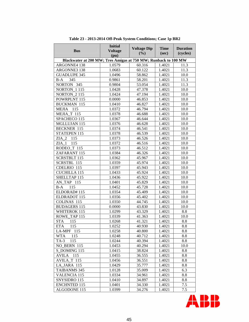
45
Table 23 - 2013-2014 Off-Peak System Conditions; Case 1p BR2
Bus
Initial
Voltage
(pu)
Voltage Dip
(%)
Time
(sec)
Duration
(cycles)
Blackwater at 200 MW; Tres Amigas at 750 MW; Runback to 100 MW
ARGONNE4 138 1.0579 60.316 1.4021 11.3
ARGONNE3 138 1.0683 60.122 1.4021 11.3
GUADLUPE 345 1.0496 58.862 1.4021 10.0
B-A 345 0.9861 58.201 1.4021 11.3
NORTON 345 0.9804 53.054 1.4021 11.3
NORTON_1 115 1.0428 47.378 1.4021 10.0
NORTON_2 115 1.0424 47.194 1.4021 10.0
POWRPLNT 115 0.0000 46.853 1.4021 10.0
BUCKMAN 115 1.0410 46.827 1.4021 10.0
MEJIA 115 1.0372 46.794 1.4021 10.0
MEJIA_T 115 1.0378 46.688 1.4021 10.0
SPACHECO 115 1.0367 46.644 1.4021 10.0
MGLLUJAN 115 1.0376 46.628 1.4021 10.0
BECKNER 115 1.0374 46.541 1.4021 10.0
STATEPEN 115 1.0378 46.539 1.4021 10.0
ZIA_2 115 1.0373 46.526 1.4021 10.0
ZIA_1 115 1.0372 46.516 1.4021 10.0
RODEO_T 115 1.0373 46.512 1.4021 10.0
ZAFARANT 115 1.0384 46.326 1.4021 10.0
SCRSTBLT 115 1.0362 45.967 1.4021 10.0
SCRSTBL 115 1.0359 45.974 1.4021 10.0
CDELRIO 115 1.0397 45.943 1.4021 10.0
CUCHILLA 115 1.0433 45.924 1.4021 10.0
SHELLTAP 115 1.0436 45.922 1.4021 10.0
AN_TAP 115 1.0401 45.829 1.4021 10.0
B-A 115 1.0452 45.728 1.4021 10.0
ELDORAD# 115 1.0354 45.409 1.4021 10.0
ELDRADOT 115 1.0356 45.402 1.4021 10.0
COLINAS 115 1.0350 44.745 1.4021 10.0
BUDAGERS 115 0.0000 43.830 1.4021 10.0
WHITEROK 115 1.0299 43.329 1.4021 8.8
ROWE_TAP 115 1.0339 41.363 1.4021 10.0
STA 115 1.0268 41.321 1.4021 8.8
ETA 115 1.0252 40.930 1.4021 8.8
LA-MPF 115 1.0258 40.800 1.4021 8.8
WTA 115 1.0248 40.712 1.4021 8.8
TA-3 115 1.0244 40.394 1.4021 8.8
NO_BERN 115 1.0453 40.294 1.4021 10.0
S_DOMING 115 1.0415 38.824 1.4021 8.8
AVILA 115 1.0455 36.555 1.4021 8.8
AVILA_T 115 1.0456 36.551 1.4021 8.8
LA_JARA 115 1.0429 35.777 1.4021 8.8
TAIBANMS 345 1.0128 35.009 1.4021 6.3
VALENCIA 115 1.0334 34.961 1.4021 8.8
SNYSIDRO 115 1.0410 34.897 1.4021 8.8
ENCHNTED 115 1.0401 34.330 1.4021 7.5
ALGODONE 115 1.0399 34.276 1.4021 7.5

46
Bus
Initial
Voltage
(pu)
Voltage Dip
(%)
Time
(sec)
Duration
(cycles)
ARRIBA 115 1.0311 33.944 1.4021 8.8
GALLINAT 115 1.0313 33.937 1.4021 8.8
ARRIBA_T 115 1.0314 33.927 1.4021 8.8
STORRIE 115 1.0309 33.404 1.4021 7.5
PRGRSS 115 1.0380 31.693 1.4021 6.3
PACHMANN 115 1.0391 31.669 1.4021 6.3
3AMIGAS 399 1.0849 29.858 1.7562 1.3
Table 24 - 2013-2014 Off-Peak Stability Results; Dynamic Compensation Requirements
Case
No. Description
Guadalupe
Dynamic
Compensation
(MVAr)
Post-Fault
Static
Compensation1
(MVAr)
Guadalupe
345 kV
Voltage
(pu)
Blackwater
345 kV
Voltage
(pu)
1p-
BR2
1-Phase fault on BA-Rio
Puerco 345 kV line at BA
345 kV. Trip both BA-Rio
Puerco lines in 12 cycles.
Tres Amigas Runback to
100 MW at 18 cycles.
< ±200 450 Unstable Unstable
0 Unstable Unstable
±200 450 1.6514 1.6699
0 Unstable Unstable
±250 450 1.6867 1.7196
0 1.1376 1.3456
1. 450 MVAr pre-fault static compensation for all cases

47
10.3.2 Tripping Tres Amigas and Guadalupe Fixed Reactive Compensation
Tripping the Tres Amigas HVDC transmission was initiated via the status parameters of the
machine models representing the VSC converters in the powerflow. At the specified time, both
converters were removed from service by setting the power flow machine status of each to 0. In
addition to tripping the converters, fixed reactive compensation was disconnected at the
Guadalupe 345 kV station in order to limit the post-fault overvoltages resulting from the
decreased loading on the BB line. Both the trip and the MSSC switching were initiated 6 cycles
after fault clearing, allowing for a 100 ms communications delay between the B-A station and
the Guadalupe and Tres Amigas stations. Breaker operating time for switching the shunt MSSC
bank was 3 cycles.
The results of the dynamic simulations with Blackwater in SVC mode and Tres Amigas
operating at 750 MW indicate that tripping the Tres Amigas HVDC transmission is sufficient to
stabilize the post fault recovery of the system without voltage violations. With Blackwater
operating at 200 MW, it is unclear as to whether or not tripping Tres Amigas stabilizes the
system recovery. Initially, the system is slow to recover and appears to recover about 6 seconds
after the fault is cleared. However, at about 9 seconds, the Blackwater HVDC transmission
becomes unstable and the transmitted dc power is reduced to zero. This is thought to be the
result of an instability in the PSLF Blackwater HVDC model brought on by the weakened post-
fault system configuration. Additional study is recommended for this scenario when a more
detailed technical study is performed. Voltage violations for the case are listed below in Table
25.
Table 25 -2013-2014 Off-Peak System Conditions; Case 1p BR2
Bus
Initial
Voltage
(pu)
Voltage Dip
(%)
Time
(sec)
Duration
(cycles)
Blackwater at 200 MW; Tres Amigas at 750 MW; Trip Tres Amigas at 18 cycles
3AMIGAS 345 1.0498 81.542 2.8604 8.7
BLACKWTR 345 1.0463 80.623 3.6312 10.0
TAIBANMS 345 1.0128 56.218 1.6937 7.5
ARGONNE3 138 1.0683 40.566 1.6729 8.8
ARGONNE4 138 1.0579 39.969 1.6937 7.5
GUADLUPE 345 1.0496 39.170 1.7146 6.3
10.3.3 Tripping Tres Amigas, Blackwater, and Guadalupe Fixed Reactive Compensation
In addition to tripping the Tres Amigas HVDC transmission as described above, this switching
scenario initiated tripping of the Blackwater HVDC transmission via the status parameters of the
dcc models representing the conventional HVDC converters in the powerflow. At the specified
time, both the Tres Amigas and Blackwater converters were removed from service by setting the
power flow model status for each to 0. In addition to tripping the converters, reactive
compensation was disconnected at the Guadalupe 345 kV station in order to limit the post-fault
overvoltages resulting from the decreased loading on the BB line. Both the trip and the MSSC
switching were initiated 6 cycles after fault clearing. Breaker operating time for switching the
MSSC bank was 3 cycles.

48
With Blackwater at 200 MW and Tres Amigas at 750 MW, the results of the dynamic simulation
indicate that tripping both the Tres Amigas and Blackwater HVDC transmissions is sufficient to
stabilize the post fault recovery of the system. Voltage violations for the case, listed below in
Table 26, were limited primarily to the Blackwater station and vicinity. With Blackwater in
SVC mode, tripping both the Tres Amigas and Blackwater HVDC transmissions stabilized the
post-fault system recovery without any voltage violations.
Table 26 - 2013-2014 Off-Peak System Conditions; Case 1p BR2
Bus
Initial
Voltage
(pu)
Voltage Dip
(%)
Time
(sec)
Duration
(cycles)
Blackwater at 200 MW; Tres Amigas at 750 MW; Trip Tres Amigas & Blackwater at 18 cycles
3AMIGAS 345 1.0498 44.352 1.4021 1.3
BLACKWTR 345 1.0463 44.154 1.4021 1.3
ARGONNE3 138 1.0683 41.295 1.4021 2.5
TAIBANMS 345 1.0128 41.261 1.4021 1.3
ARGONNE4 138 1.0579 39.538 1.4021 2.5
GUADLUPE 345 1.0496 37.389 1.4021 1.3

49
11 PNM Transfer Analysis without Dynamic voltage support
During the course of Phase 1 analysis it was mutually agreed by PNM and Tres Amigas to
evaluate the project without dynamic voltage support at Guadalupe station and the synchronous
condenser at the Tres Amigas station to determine what total transfers could take place absent
network upgrades. This analysis was performed by PNM in parallel to the work being performed
by ABB. This section summarizes the analysis performed and its results.
The analysis reviewed a normal system configuration with all transmission facilities in service
along with the most limiting contingencies for transfers to and from the BB line in northern New
Mexico. Table 27 below lists the scenarios considered for this transfer analysis. These are used
as the metric for determining total transfer capability absent dynamic voltage support.
Table 27 - Scenarios considered for Transfer Analysis
Case Description
All Transmission Facilities in Service
Four Corners-West Mesa 345 kV Outage
Rio Puerco-San Juan 345 kV Outage
BA-Norton 345 kV Outage
11.1.1 Transfer Case development
Four transfer cases were created out of the post project cases that ABB has created for the study:
Case Direction
Blackwater
Schedule
(MW)
2015 Heavy
Summer East-to-West
200
0
2013-14 HW1A
Off-peak West-to-East
200
0
Aragonne Mesa and NM Wind Energy Center wind farms were off-line and not contributing to
reactive power requirements of the B-A – Blackwater line for the purposes of determining total
transfer capability.
11.2 Voltage Stability
PV analysis was performed to determine how much power could be transferred in a steady state
powerflow model. The Tres Amigas project transfer was incremented or decremented in the
analysis to determine when voltage collapse would occur at the Guadalupe 345 kV station for
any of the contingencies listed in Table 27. The limit is established at 5% below the total
transfer at the voltage collapse point based on WECC criteria. Dynamic stability analysis is then

50
performed at the transfer limit to verify a lower dynamic stability limit is not present. The
maximum transfers achieved are plotted in Error! Reference source not found. below for the
ontingencies in Table 27. Table 288 shows the results of this analysis in tabular format.
Figure 14 - PV Analysis Plots
Table 28: Voltage stability limit without dynamic voltage support
Case Type Transfer Direction Tres Amigas
Transfer
Blackwater
Transfer
Total
Transfers
2015 Peak E-W 480 200 680 2015 Peak E-W 676 Off-line 676
2013-14 Off-peak W-E 371 200 571 2013-14 Off-peak W-E 550 Off-line 550
11.3 Stability Analysis
Once the transfer limit was established based on voltage stability, dynamic stability simulations
at the transfer limits were performed to ensure stable operation. Table 2929 below represents the
maximum Tres Amigas Transfers limited by the implied behavior of the dynamic model
provided for the project.

51
Table 29: Stability Analysis Results
Case Type Transfier Direction Tres Amigas
Transfer
Blackwater
Transfer
Total
Transfers
2015 Peak E-W 377 200 577 2015 Peak E-W 450 Off-line 450
2013-14 Off-peak W-E 355 200 555 2013-14 Off-peak W-E 450 Off-line 450

52
12 Conclusions and Recommendations
The purpose of the preceding study was to evaluate the interconnection of the 750 MW Stage 1
Tres Amigas VSC HVDC transmission facility between the PNM transmission system at Clovis,
New Mexico and the SPP transmission system at the Tolk generating station east of Muleshoe,
Texas. The proposed transmission facility is approximately in parallel with the existing PNM
Blackwater HVDC interconnection at Clovis. Due to the lack of available firm transmission
capacity in the vicinity of the Blackwater station, the present study was to evaluate
interconnecting and transferring power in and out of the Project on an “as available” basis only,
using only non-firm transmission capacity. The objectives of the Study included:
1. An assessment of the short circuit capacity at the Blackwater Station to determine if
sufficient system strength is available to support simultaneous operation of the Tres
Amigas and Blackwater facilities.
2. An analysis of the reactive power and AC voltage control strategies of the Tres Amigas
and Blackwater HVDC converters.
3. An assessment of the steady state and dynamic performance of the PNM transmission
system with the addition of Stage 1.
Peak load conditions were considered for east-to-west transfers while only off-peak load
conditions were considered for west-to-east transfers. Base cases included both operation of the
Blackwater converters at rated capacity and in Static Var Compensator (“SVC”) mode. ABB,
Inc. was retained by PNM to perform the analysis with support from PNM.
Short Circuit Capability Assessment
The results of the short circuit capability assessment determined that there is not sufficient short
circuit capability at the Blackwater Station to support the simultaneous operation of the Project
and the existing 200 MW Blackwater Station. The short circuit requirements for the Project
converters are not fully known due to the simplified positive sequence models used for the
Study. To provide enough short circuit capability to support the operation of both the Project
and Blackwater Station, the Study assumed this capacity would be provided by synchronous
condensers Tres Amigas would locate at the Project station. To maintain acceptable dynamic
system performance, the size of the synchronous condenser was established at 250 MVA.
Steady-State Performance
The powerflow analysis shows that substantial additional voltage support will be required to
accommodate the combined total power transfer of the Project and the Blackwater Station. The
total current associated with the full 950 MW westbound power transfer requirement on the BB
line remained below the conductor thermal rating (1076 MVA) but exceeded the BB line
wavetrap rating (717 MVA) and the voltage stability limit of 371 MVA identifyied in the
analysis3. When modeling the full transfer requirement in the eastbound direction, the maximum
transfer that could be accomodated without exceeding the thermal limit was 925 MW. As with
the westbound direction, the maximum transfer was found to be limited to 480 MW without
3 This voltage stability limit was established by powerflow studies. Due to its length, the BB has relatively low
surge impedance loading (426 MVA). Without compensation, it cannot be loaded much more than the surge
impedance loading because angle stability cannot be maintained.

53
substantial additional voltage support along the BB line and to no more than 717 MVA without
replacement of the BB line wavetraps.
The additional voltage support requirements identified along the BB line to support the total
power transfer from west-to-east included the addition of 450 Mvar of MSSC banks at the
Guadalupe 345 kV station in order to maintain stable operation for worst case off-peak system
conditions. Based on requirements for the various system configurations examined, a maximum
step size of 150 Mvar for the MSSCs is recommended. In addition to the MSCCs, the addition
of a ±250 Mvar SVC at Guadalupe is required in order to meet both the dynamic stability
performance requirements and voltage change requirements for switching the MSSC banks.
In addition to the above requirements, an outage of the BB line for the westbound transfers can
cause 115 kV station voltages in the Albuquerque area to rise above acceptable limits. Since
PNM does not currently have automatic voltage-controlled shunt devices on the system in the
Albuquerque area that could be used to limit 115 kV overvoltages, an automatic voltage-
controlled shunt reactor at the BA 115 kV station may be required.
Dynamic Analysis for Small-Signal Disturbances
Dynamic simulations of capacitor/reactor switching scenarios at Blackwater and Guadalupe
345 kV stations were performed to determine the closed-loop dynamic voltage stability of the
combined Blackwater/Tres Amigas systems. All cases are stable and meet the PNM stability
performance criteria with no evidence of control instabilities in either the Blackwater or Tres
Amigas controls.
Dynamic Stability Performance
Dynamic stability violations were identified for off-peak system conditions. The violations
occur for a single line to ground fault with delayed clearing (breaker failure scenario) at the B-A
345 kV station resulting in the double line outage of both BA-Rio Puerco 345 kV circuits. This
contingency is the driver for the size requirements of the 250 Mvar SVC at Guadalupe.
Even with the SVC, remedial actions are required for this contingency. The following scenarios
were considered:
1. Runback of the Tres Amigas power schedule combined with tripping the MSSC banks at
Guadalupe.
2. Tripping Tres Amigas and the Guadalupe MSSC banks
3. Tripping Tres Amigas, the Blackwater Station, and the Guadalupe MSSC banks
The results of the study indicate that either scenario 1 or 2 is sufficient to stabilize the system.

54
Short Circuit Analysis
Short circuit studies were conducted to determine if the existing circuit breakers, particularly at
Blackwater and BA, can handle the increased fault currents associated with the Tres Amigas
project. Based on these results, the existing circuit breakers are adequate.
Blackwater Facilities
The interconnection of the project will require the addition of a 345 kV three breaker ring bus at
Blackwater. The existing station consists of a single breaker for isolating the Blackwater Station
from the BB line.
Conclusions
The results presented in this report show that the Project will require several system
improvements for the “as available” transmission service scenario assumed in the Study. The
minimum system improvements required to support the full 950 MW combined transfer
capability of the Blackwater and Tres Amigas facilities include:
250 MVA synchronous condenser to be located at the Project station.
3 - 150 Mvar MSSC banks to be located at the Guadalupe 345 kV station.
±250 Mvar SVC to be located at the Guadalupe 345 kV station.
Expand the Blackwater Station from a single breaker to a three breaker 345 kV ring bus
station.
Re-conductor the BA-Guadalupe 345 kV line.
Replace the communication wave trap on the BB line.
An automatic voltage-controlled shunt reactor to be located at the BA 115 kV station.
The Study also identified the maximum transfer in or out of the Project absent the system
improvements identified above, excluding the expansion of the Blackwater switchyard. These
maximum transfers are summarized in the table below:
Without System Improvements
Transfer Direction Tres Amigas (MW) Blackwater (MW) Total (MW)
East to West 377 / 480 200 577 / 680 East to West 450 / 676 off-line 450 / 676 West to East 355 / 371 200 555 / 571 West to East 450 / 550 off-line 450 / 550
The first number reflects reduced transfer levels to address apparent operational limitations of
the Project likely resulting from the lack of adequate short-circuit capacity at the Blackwater 345
kV switchyard. The limitations are implied by the behavior of the dynamic model provided for
the Project. The second number reflects voltage stability limitations of the BB line.
Discussions with Tres-Amigas have indicated that estimates for the scenario without system
improvements are of primary interest. As a result cost estimates included in the Study are
limited to expansion of the Blackwater 345 kV switching station into a three breaker ring bus.
The cost estimate and schedule are summarized below:

55
Interconnection item Cost
Estimated
Time for construction
Expand the Blackwater Station from a single to three breakers $7 M 18 months
The results of this analysis are preliminary and may be modified based on more detailed
technical study (Phase 2) to analyze the control interactions between devices, temporary over-
voltages, coordination of control and protection, evaluation of single pole switching, low order
harmonic resonance, AC filter performance and dynamic over voltages. Furthermore, future
studies will be required to identify the necessary transmission line and station additions for
utilization of the Project that exceeds the “as available” service limitations assumed in the Study
once users of Tres Amigas make firm point-to-point transmission delivery service requests.
Nothing in this Study is intended to imply any right to receive transmission service from PNM
until such upgrades are defined and in-service.
The results of the Study are based on available data and assumptions made at the time of
conducting the Study. The results provided in this report may not apply if any of the data, models
and/or other assumptions used to perform the Study change.

56
13 References
[1] ABB Technical Report 2010-E3019-1.1.R00, “Blackwater HVDC Upgrade Project
PSLF Powerflow Model”, February 5, 2010.
[2] ABB Technical Report 2010-E3019-2.1.R00, “Blackwater HVDC Upgrade Project
PSLF Dynamics Model”, February 5, 2010.
[3] GE Technical Report, “Voltage Source Converter User Written Model – Final Report”,
October 17, 2011.
[4] Anderson and Fouad, “Power System Control and Stability”, The Iowa State University
Press, 1977