power system protection coordination studies at gas ...utpedia.utp.edu.my/7992/1/2009 - power system...
TRANSCRIPT
Power System Protection Coordination Studies at Gas Processing Plant B (GPPB),
PETRONAS Gas Berhad (PGB), Paka
By
SITI FATHIMAH BT HARUN
DISSERTATION REPORT
Submitted to the Electrical & Electronics Engineering Programme
in Partial Fulfillment of the Requirements
for the Degree
Bachelor of Engineering (Hons)
(Electrical & Electronics Engineering)
Universiti Teknologi Petronas
Bandar Seri Iskandar
31750 Tronoh
Perak Darul Ridzuan
© Copyright 2009
by Siti Fathimah Harun, 2009
Approved:
CERTIFICATION OF APPROVAL
Power System Protection Coordination Studies at Gas Processing Plant B (GPPB),
PETRONAS Gas Berhad (PGB), Paka
by
Siti Fathimah Bt Harun
A project dissertation submitted to the
Electrical & Electronics Engineering Programme
Universiti Teknologi PE1RONAS
in partial fulfillment of the requirement for the
Bachelor of Engineering (Hons)
(Electrical & Electronics Engineering)
Ir. Mohd Faris Bin Abdullah
Project Supervisor
UNIVERSITI TEKNOLOGI PETRONAS
TRONOH, PERAK
December 2009
ii

CERTIFICATION OF ORIGINALITY
This is to certify that I am responsible for the work submitted in this project, that the
original work is my own except as specified in the references and
acknowledgements, and that the original work contained herein have not been
undertaken or done by unspecified sources or persons.
Siti Fathimah Bt Harun
iii

ABSTRACT
Power system protection coordination is a study on protection for power
system from any fault such as overcurrent, earthfaulth or any abnormal system
operating condition that can cause failure to the systems component for example
transformer, generator and transmission line. If any faults occur, the protection
devices will recognize faults and initiate action to clear the fault from the system. In
Gas Processing Plant B (GPPB), the protection system is an important part to take
care but sometimes for some reason, the protection system is not work as what we
want, therefore the studies on this project will be help the company to improve the
current protection systems. This study is based on some characteristics in power
system protection and develops the current power system protection coordination
for Gas Processing Plant B (GPPB). With this new protection system coordination,
the author hopes to help the company to improve the current protection systems.
iv
ACKNOWLEDGEMENT
The author would like to express her gratitude toward her supervisor, Ir
Mohd Faris B. Abdullah, Electrical and Electronics lecturer, Universiti Teknology
Petronas for the guidance throughout this project. A lot of new knowledge the
author learnt from him, and he always ready to answer all the questions regarding to
the project and share his experience before at TNB while doing the similar project
as the author did. There are a lot of tips that he gives and helped the author to finish
the project. Thank you for your help, support and motivation.
Also, thank you to the author friends that helped a lot and encouraged the
author not to give up at the first stage to start the project where at that stage it gives
the author a big challenges to understand the project requirement. Especially to the
author's group that work under the same supervisor as the author and have kind of
similarities in their project with the author. The author's group always discuss if
there is a misconception regarding the project. Thank you friends because be able to
be with the author even in critical period.
Last but not least, thank you to my family especially to the author's mother
and father also to other family members for their constant support and always
motivate to the author. With their support, the author becomes more motivated and
inspired to finish the project.
Lastly, thank you to Universiti Teknologi Petronas for assisting and
supporting in this project. UTP play an important role in the author project. UTP
provide the author with the main equipment that needs in order to complete the
project which is the ERACS software. Also UTP support this project by gives some
financial support to make sure this project completed successfully.
v
TABLE OF CONTENTS
ABSTRACT ................................................................................... iv
AC~OWLEDGEMENT ................................................................... v
LIST OF FIGURES ......................................................................... ix
LIST OJ? Ti\JEILES ..............................................................•........... Jti
CHAPTER I
INTRODUCTION
1.1 Project Background ...................................................................... 1
1.2 Problem Statement ........................................................................ 2
1.3 Objectives ................................................................................. 2
1. 4 Scope of study ............................................................................ 2
CHAPTER2
LITERATURE REVIEW
2.1 Basic Component in distribution Network ............................................ 3
2.1.1 Sensing Device ................................................................ 5
2.1.1.1 Current Transformer ............................................... 5
2.1.1.2 Voltage Transformer .............................................. 6
2.1.2 Relay ............................................................................ 6
2.1.3 Circuit Breaker ................................................................ 8
2.2 Types of Distribution Protection ....................................................... 9
2.2.1 Non-unit Protection ........................................................... 9
2.2.2 Unit Protection ................................................................. 9
2.2.3 Overcurrent and Earthfault Protection .................................... 10
vi

2.2.3.I Overcurrent Protection .......................................... 11
2.2.3 .2 Earthfault Protection ............................................. II
2.3 Protection Relay Coordination ........................................................ II
2.3.I Load Flow Analysis ......................................................... 11
2.3.2 Fault Calculation ............................................................ I2
2.3.3 Protection Coordination ..................................................... I2
2.3.3.I Grading Margin criteria .......................................... 12
2.3.3.2 Plug Setting (PS) ................................................. 13
2.3.3.3 Time Multiplier Setting (TMS) ................................. 13
2.3.3.4 Relay Calculation Steps .......................................... 14
CHAPTER3
MEmODOLOGY
3.1 Procedure Identification ............................................................... 15
3.2 Tools and Equipment Required ....................................................... 16
vii

CHAPTER4
RESULT AND DISCUSSION
4.1 Result ................................................................................... 17
4.2 Discussion ............................................................................... 20
4.2.1 Relay Coordination for Overcurrent Protection ......................... 20
4.2.1.1 Full Load Current at 132kV .................................... 20
4.2.1.2 Full Load Current at 33kV ...................................... 20
4.2.2 Grading Margin for Overcurrent Protection .............................. 22
4.2.2.1 IDMT l-2 .......................................................... 22
4.2.2.2 IDMT 1-3 .......................................................... 26
4.2.2.3 IDMTcable 1, IDMT cable 1-2 and IDMT .................. 30
4.2.2.4 IDMT 1 ............................................................ 34
4.2.2.5 IDMT 1-busbar, IDMT 1-motor and IDMT 2-motor ........ 35
4.2.3 Relay Coordination Earthfault Protection ................................ 37
4.2.3.1 Current at 132kV ................................................. 37
4.2.3.2 Current at 33kV ................................................... 37
4.2.4 Grading Margin for Earthfault Protection ................................ 39
4.2.4.1 IDMT 1-l, IDMT 1-2 ............................................ 39
4.2.4.2 IDMT 1-3, IDMT cable-!, IDMT cable-2 and IDMT ....... 41
4.2.4.3 IDMT 1 ............................................................ 44
4.2.4.4 IDMTI-busbar, IDMTI-motor and IDMT2-motor .......... 45
CHAPTERS
CONCLUSION AND RECOMMENDATION
5.1 Conclusion ................................................................................ 50
5.2 Recommendation ........................................................................ 51
REFERENCES ............................................................................. 52
APPENDIXES .............................................................................. 53
viii

LIST OF FIGURES
Figure I: Basic component of a protective system 3
Figure 2: Connection current transformer to the network 5
Figure 3: Connection of voltage transformer 6
Figure 4: Graph time-current characteristic for different relays 7
Figure 5: Vacuum circuit breaker use at high voltage 8
Figure 6: Non-unit Protection 9
Figure 7: Unit Protection I 0
Figure 8: Example connection ofOvercurrent and Earthfault (OCEF) relays to
the three phase network I 0
Figure 9: Flow chart of project 15
Figure I 0: Network of GPPB inside ERACs software 17
Figure 11: LocationofiDMT 1-1 andiDMT 1-2 22
Figure 12: Result of Coordination Protection IDMT 1-2 24
Figure 13: Graph for IDMT 1-1 and IDMT1-2 25
Figure 14: Location ofiDMT 1-3 26
Figure 15: Result of Coordination Protection IDMT 1-3 27
Figure 16: Graph for IDMTl-2 and IDMT 1-3 28
Figure 17: Result for IDMTl-2 and IDMT 1-3 29
Figure 18: Location ofiDMT cable 1, IDMT cable 1-2 and IDMT 30
Figure 19: Result of Protection coordination IDMT cable 1, and IDMT 1-3 31
Figure 20: Graph for IDMT 1-3 and IDMT-cablel 31
Figure 21: Result of Protection coordination IDMT 32
Figure 22: Graph for IDMT 1-3, IDMT cable 1, IDMT cable 1-2 and IDMT 33
Figure 23: Location ofiDMTl, IDMTl-busbar, IDMTl-motor,
and IDMT2-motor 34
Figure 24: Result of protection coordination for IDMT2-motor 35
Figure 25: Graph for IDMT 1-busbar, IDMT 1-motor and IDMT 2-motor 36
Figure 26: Location of relays 39
ix

Figure 27: Result ofEarthfault Protection Coordination for IDMT 1-2 40
Figure 28: Graph for Earthfault Protection for relay IDMT 1-1 and IDMT 1-2 41
Figure 29: Result for Earthfault Protection for relay IDMT 1-3 42
Figure 30: Earthfault current at Cable 1 43
Figure 31: Graph for Earthfault current IDMTl-cable 43
Figure 32: Result Earthfault current for IDMTl 44
Figure 33: Graph for Earthfault current IDMTl-cable 45
Figure 34: Result IDMTl-busbar for earthfault protection 46
Figure 35: Graph for IDMT 1 and IDMT 1-busbar 47
Figure 36: Result IDMTl-motor for Earthfault Protection 4 7
Figure 37: Graph for IDMT1-busbar and IDMTl-motor 48
Figure 38: Result IDMT2-motor for earthfault protection 48
Figure 39: Graph for IDMTl-busbar, IDMTI-motor and IDMT2-motor 49
X

LIST OF TABLES
Table 1: PS and TMS Overcurrent values for first path
Table 2: PS and TMS Earthfault values for first path
Table 3: List of Plug Setting for Overcurrent Protection
Table 4: Fault current and impedance for grid 1
Table 5: List of Plug Setting for Earthfault Protection
xi
18
19
21
23
38

1.1 Background of Study
CHAPTER I
INTRODUCTION
This study is intended to evaluate current power system protection
coordination at Gas Processing Plant B (GPPB), Power system protection is a
protection system used to protect important electrical component such as
transformer, generator, bus structures, transmission line and even the loads that
connected to the system from any fault, hazard such as short circuit or any abnormal
system operating condition that would eventually cause failure of one or more
system components. Therefore, the action is usually to isolate the portion of system
experiencing the hazard so that the rest of system can operate normally as fast as
possible. In doing so, the equipment will be safeguarded from further damage and
more importantly from endangering human life. Having this criteria set and adhered
to one can look at the second important objective that is to minimize interruptions.
There is number of protective device available which are fuses, relays and circuit
breakers.
The studies are basically on the characteristic of all protective devices and
find in the suitable coordination that can be the best way to protect all power system
components at Gas Processing Plant B (GPPB)
1

1.2 Problem Statement
Power system protection miscoordination had been observed to occur at
GPPB during the tripping of the upstream protection when there was a fault at the
downstream. A well coordinated protection system would allow the downstream
protection to clear the fault discriminatively, hence reducing the load loss.
1.3 Objeetive of Study
1. To study the power system protection at Gas Processing Plant B,
PETRONAS Gas Plant, Paka (GPPB, PGB).
2. To study on characteristic of each power system protection devices.
3. To improve current power system protection coordination at Gas
Processing Plant B, PETRONAS Gas Berhad (GPPB, PGB).
1.4 Scope of Study
The studies are based on the electrical power system protection,
characteristics of protection devices such as fuses, relays and circuit breaker,
overcurrent and earthfault relay coordination and setting. Also this project will
cover studies on coordination of overcurrent relays, differential relaying, and
restricted earth fault protection.
Other than that, this project is mostly deal with ERACS software to get the
best coordination of overcurrent setting and earthfault setting for power system
protection in Gas Processing Plant (GPPB). The author will be exposing to the
usage of the features in this new software through out this studies.
2

CHAPTER2
LITERATURE REVIEW
Main purpose of distribution protection and electrical protective devices is
to isolate the faulted component from the healthy parts as fast as possible. In doing
so, the equipment will be safeguarded from further damage and more importantly
from endangering human life. Also it is important to ensure that the distribution
network can operate with preset requirement for the safety of public, staff and
overall network including individual equipment. Having these criteria set then one
can look at the second important objective, that is, to minimize interruptions or the
cost of non-distributed energy.
2.1 Basic Component in Distribution Network
c "-
reaker SenllinaAdevice .
,. R•Jay
Trip
Ftgure 1: Baste component of a protective system
There are three basic components in distribution network as show in Figure 1 which
are:
a) Sensing device
b) Relay
c) Circuit Breaker
3

When the fault occur along the network, the nearest sensing device will
detect the fault in term of changes in measurement of basic electricity components
which are current, voltage, or frequency. The measured quantity then sent to other
basic component in distribution network which is relay. Relay act as decision maker
for the network whether to isolate the faulted network or not. The decision is
depending on the relay setting magnitude of the selected measured quantity. If
measured quantity exceed relay setting then the relay will make the circuit breaker
to trip therefore the faulted path will be isolated.
When designing, we have to make sure that the protection system 1s
selective, sensitive, stable, fast and reliable.
a) Selective - Relay systems should only trip as much of the system as
necessary to de-energize distressed components.[5]
b) Sensitive - Sensitive enough to operate under minimum fault
condition.(!]
c) Stable - Stable and remain inoperative under certain specified
conditions such as transmission system disturbance, through faults,
transients, etc. [I]
d) Fast- Fast operation in order to clear the fault from the system thns
to mininllze damage to the affected components.[ 1]
e) Reliable - The protective equipment should not fail to operate in the
events of faults in the protected zone. It may be necessary to provide
backup protection to cover the failure of the main protection.[!]
4
2.1.1 Sensing Device
First component in protection system is sensing device. Usually use as
sensing devices are current transformer and voltage transformer. Both use to
facilitate the changes in current or voltage within some range.
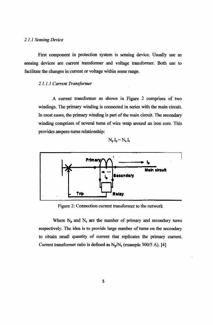
2.1.1.1 Current Transformer
A current transformer as shown in Figure 2 comprises of two
windings. The primary winding is connected in series with the main circuit.
In most cases, the primary winding is part of the main circuit. The secondary
winding comprises of several turns of wire wrap around an iron core. This
provides ampere-turns relationship:
• l '~
Prlm•fl'(Y', 1,.
'. ~ ·- M•ln olroul I, laoondlry
~ Trip O~--··y Figure 2: Connection current transformer to the network
Where Np and N, are the number of primary and secondary turns
respectively. The idea is to provide large number of turns on the secondary
to obtain small quantity of current that replicates the primary current.
Current transformer ratio is defined as Np/N; (example 300/5 A). [4]
5
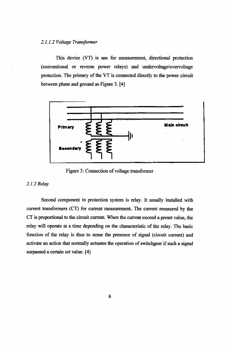
2.1.1.2 Voltage Transformer
This device (Vn is use for measurement, directional protection
(conventional or reverse power relays) and undervoltage/overvoltage
protection. The primary of the VT is connected directly to the power circuit
between phase and ground as Figure 3. [4]
I • ;:!. ;:!.
Primary = = = -- -- .....
M aln olroult
Figure 3: Connection ofvoitage transformer
2.1.2 Relay
Second component in protection system is relay. It usually installed with
current transformers (CT) for current measurement. The current measured by the
CT is proportional to the circuit current. When the current exceed a preset value, the
relay will operate at a time depending on the characteristic of the relay. The basic
function of the relay is thus to sense the presence of signal (circuit current) and
activate an action that normally actuates the operation of switchgear if such a signal
surpassed a certain set value. [4]
6

IDMT·~-
Current (A)
Figure 4: Graph time-current characteristic for different relays
Relays are normally classified into the time/current characteristics as shown
in graph above:
• Instantaneous
• Defini~ Time
• Inverse Definite Minimum Time (IDMT)
Standard Inverse: t = 0.14
(f·02-1)
x time setting sees
Extremely Inverse: t= 0.14 x time setting sees
(!2-l)
Very Inverse: t = 0.14 x time setting sees
(1-1)
7
Throughout this project, the author use standard mverse IDMT relay
characteristic which have the equation:
0.14 X 1MS I =
( ~_UL_T __ C_URRE __ NT_ SETilNG CURRENT )
0 .02
- 1
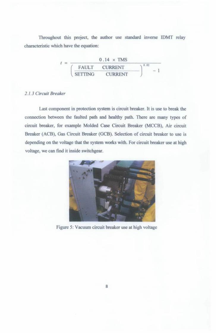
2.1. 3 Circuit Breaker
Last component in protection system is circuit breaker. It is use to break the
connection between the faulted path and healthy path. There are many types of
circuit breaker, for example Molded Case Circuit Breaker (MCCB), Air circuit
Breaker (ACB), Gas Circuit Breaker (GCB). Selection of circuit breaker to use is
depending on the voltage that the system works with. For circuit breaker use at high
voltage, we can find it inside switchgear.
Figure 5: Vacuum circuit breaker use at high voltage
8

2.2 Types of distribution protection
There are various types of protection that can be considered m any
distribution network.
2.2.1 Non-unit Protection
Non-unit protection is a time/current graded system where protective
systems in successive zones are coordinated to operate at different times.
When a fault occurs, a number of relays will respond and only those closest
to the fault complete the tripping operation leaving the remaining relays
reset. [1]
SS1
~-s_e_c ________ ~
~ 0 sec
Figure 6: Non-unit Protection
2.2.2 Unit Protection
A unit protection is a protection system in which the protected zone
can be clearly identified by means of CT boundaries. Such protection does
not respond to through fault (out zone fault). It responds to only internal
faults or faults inside the protected zone. As shown in Figure 7. [1]
9

l--lli}··
Figure 7: UnitProtection
2.2.3 Overcurrent and Earthfault Protection
Overcurrent and Earthfault protection is used to protect feeders,
transformers, motors, capacitors and other equipment. The protection devices used
are either fuses or relays. Usually we used the combination connection between
overcurrent and earthfault (OCEF) relays like shows below. [4]
R (cT)·· .
~ .... ' .
y
,----..__ CT 8
C7 ~ ~~ II EARTH
Tl' BONOIN
Figure 8: Example connection of Overcurrent and Earthfault (OCEF)
relays to the three phase network
10
G
2.2.3.1 Overcurrent Protection
The objective for overcurrent protection is to detect fault affecting one or
two phase, Overcurrent protection involve inclusion of suitable device which is
overcurrent relay in each phase and is energized by current transformer
Magnitude of an interphase fault current depends on the impedances of the
system. Usually the phase fault current is larger. When calculating grading margin
for overcurrent relay, we use three phase fault current and the maximum load or
current carrying capacity of the cable/line/transformer will determine the setting
current.
2.2.3.2 Earthfault Protection
Earthfault protection is required to have a high sensitivity to earth faults.
Earthfault setting are often required to be lower than system rating. When
calculating grading margin for earthfault relay, we use single phase fuult current.
Normally a setting of 10%-20% from current transformer rating is used as earthfault
setting current.
2.3 Protection Relay Coordination
2.3.1 Load Flow Analysis
Load flow analysis must be done first before doing the grading
margin for protection relay coordination. Load flow analysis were run to
confirm that the busses, switchboard, Motor Control Centre (MCC),
transformer and feeder cables would operate within their ratings, and also to
determine the real and reactive power, bus voltage and load level at all
busses.
11

2.3.2 Fault Calculation
Next step we must know the current fault at every busses either three phase
current fault or single phase current fault. Fault calculation is fundamental to
protective relay setting and coordination. Knowledge of maximum 3-phase fault
MV A at any point in the system would enable one to initially set the operating time
of the relays to ensure that it is within the withstand capability of the equipment.
With knowing three phase fault, then coordination exercise can be
performed for overcurrent setting since 3-phase fault current is the highest fault
current in the system while single-phase to ground fault value is very important to
coordinate earthfault setting as this is the highest earthfault current in the system.
The criteria to choose 3-phase fault current for overcurrent setting and single-phase
to ground fault current for earthfault setting is based on normal Inverse Definite
Minimum Time (IDMT) relay characteristics.
2.3.3 Protection Coordination
2.3.3.1 Grading margin criteria
Grading margin between adjacent relays is determined by several factors:
Circuit Breaker Time
Relay overshoot
Instrument Errors
12

Two methods of determining grading margins:
• Fixed margin
Time margin is estimate as follows:
Circuit Breaker Time - O.lOsec
Relay Overshoot - 0.04sec
Relay Error - O.lOsec
Instrument Error - O.lOsec
Safety Margin - O.lOsec
Total Margin - 0.44sec
The margin could range between 0.3-0.5 sec. In practice for this
project, the author use margin 0.4 sec.
2.3.3.2 Plug Setting (PS)
Plug setting will set the minimum operating current. Usually it is in
electromechanical/electronic relay or in numerical relay.
2.3.3.3 Time Multiplier Setting (I'MS)
It gives operating time scale for maximum disc movement.
13
2.3.3.4 Relay Setting Calculation Steps
• For Transformer - the max operating time at LV side must considering
transformer damage curve. For this network, transformer damage curve
considered as 1.6 sec.
• No margin required within feeder and 0.4 sec margin between feeder
• For OC set PS =current carrying capacity and adjust TMS to get required
margin
• For EF set PS = 20% of ct ratio and adjust TMS to get required margin
For this project, all of the calculation mainly calculated by ERACS software
because it is much faster to perform calculation and without arithmetic error and
also the system that has been setup for computer calculation could be modified
easily and calculation can be repeated.
14

CHAPTER3
ME mODO LOGY
3.1 Procedure Identification
,r
"
,r
"
Understand the Project Requirement
L Data research and gathering information
Elements of studies involved in this stage include the study in power
system protection for GPPB, overcurrent and earthfault relay
coordination, characteristics of protective devices.
~ Analyse protective devices characteristic
Gather all information on fuses and relay charnctenstics and
simulate the protection system coordination.
L Designing using ERACS software
Using all information and characteristics done before, start
designing GPPB single line diagram using ERACS software and
find out the margin for the system.
~ Perform Loadflow Study
l Design Protection Coordination System
Figure 9: Flow chart or project
15
'
.I
I

3.2 Tools and Equipment
• ERACS software
ERACS software is a power system software used to calculate
the load flow study, fault analysis and calculate the protection
coordination of the network
Complete design the network for high voltage level.
Complete design the grading margin for one path of the network.
16
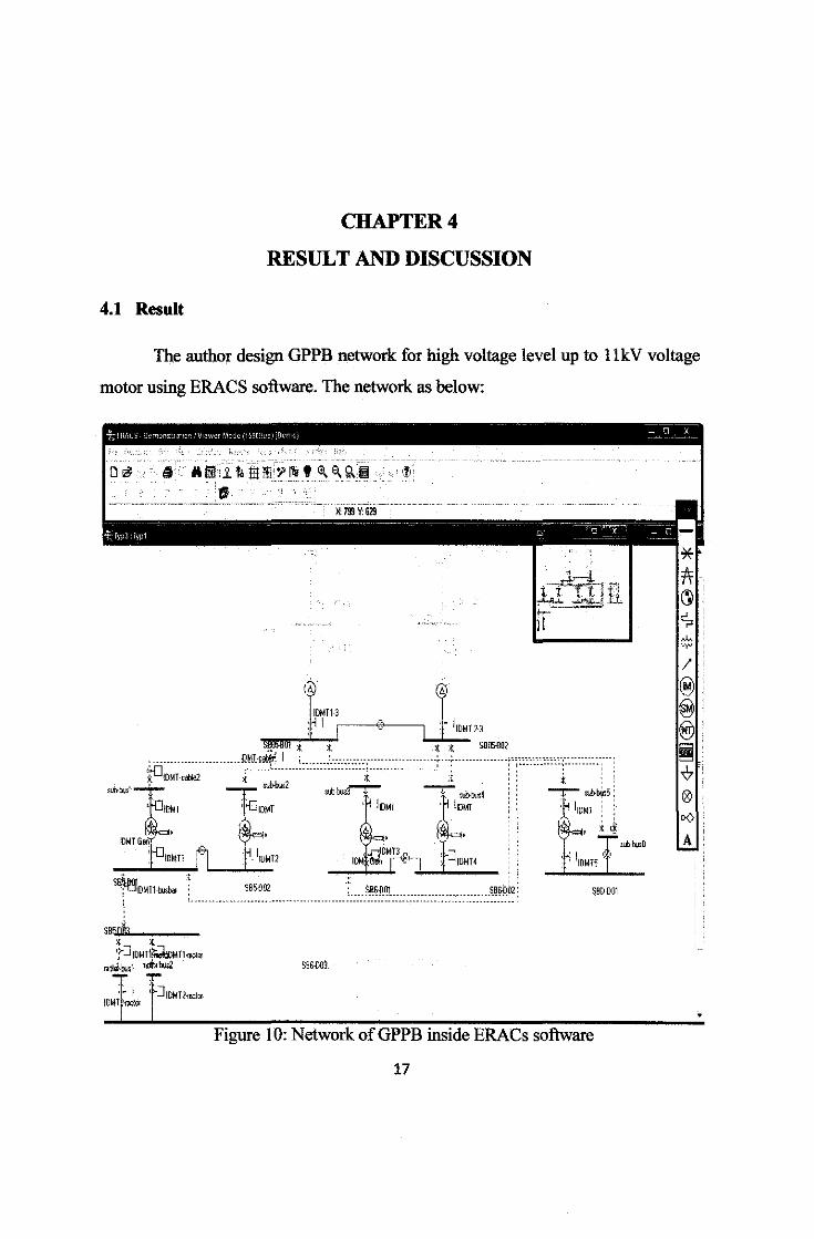
4.1 Result
CHAPTER4
RESULT AND DISCUSSION
The author design GPPB network for high voltage level up to llkV voltage
motor using ERACS software. The network as below:
(h
IDMTB :.' I .---0---, .. (
· lDMT 2·3
S86~0l
Figure 10: Network of GPPB inside ERACs software
17

Result simulation for the first path. It is including Grid 1 up to the 6.6kV
motor (PM5-0202A), the result for Plug Setting and Time Multiplier as the show in
Table l.
Table 1: PS and TMS Overcurrent values for first path
Relay Plug setting Time Multiplier Description .
IDMT 1-1 0.4 0.2 -
IDMT l-2 0.4 0.2 No margin
IDMT 1-3 0.75 0.25 Remaining time < 0.2 sec
IDMTcable l 0.75 0.175 Margin 0.4 sec
IDMTcable2 0.75 0.175 No margin
IDMT 0,75 0,175 No margin
IDMT1 0.70 0.25 Remaining time < 0.2 sec
IDMTBusbar 0.85 0.125 Margin0.4
IDMT 1 motor 0.85 0.05 Margin0.4
IDMT2motor 0.85 0.05 No margin
18
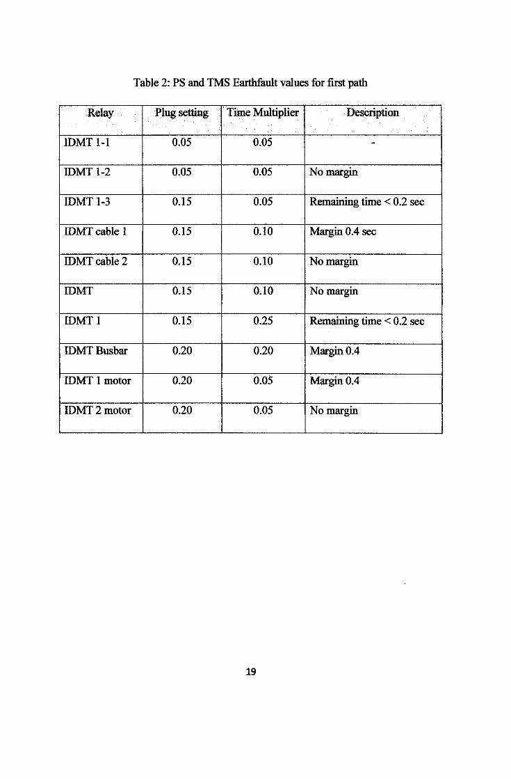
Table 2: PS and TMS Earthfault values for first path
Relay Plug setting Time Multiplier Descriptioo
IDMT 1-1 0.05 0.05 -
IDMT 1-2 0.05 0.05 No margin
IDMT 1-3 0.15 0.05 Remaining time< 0.2 sec
IDMTcable 1 0.15 0.10 Margin 0.4 sec
IDMTcable 2 0.15 0.10 No margin
IDMT 0.15 0,10 No margin
IDMT1 0.15 0.25 Remaining time < 0.2 sec
IDMTBusbar 0.20 0.20 Margin0.4
IDMT 1 motor 0.20 0.05 Margin0.4
IDMT2motor 0.20 0.05 No margin
19
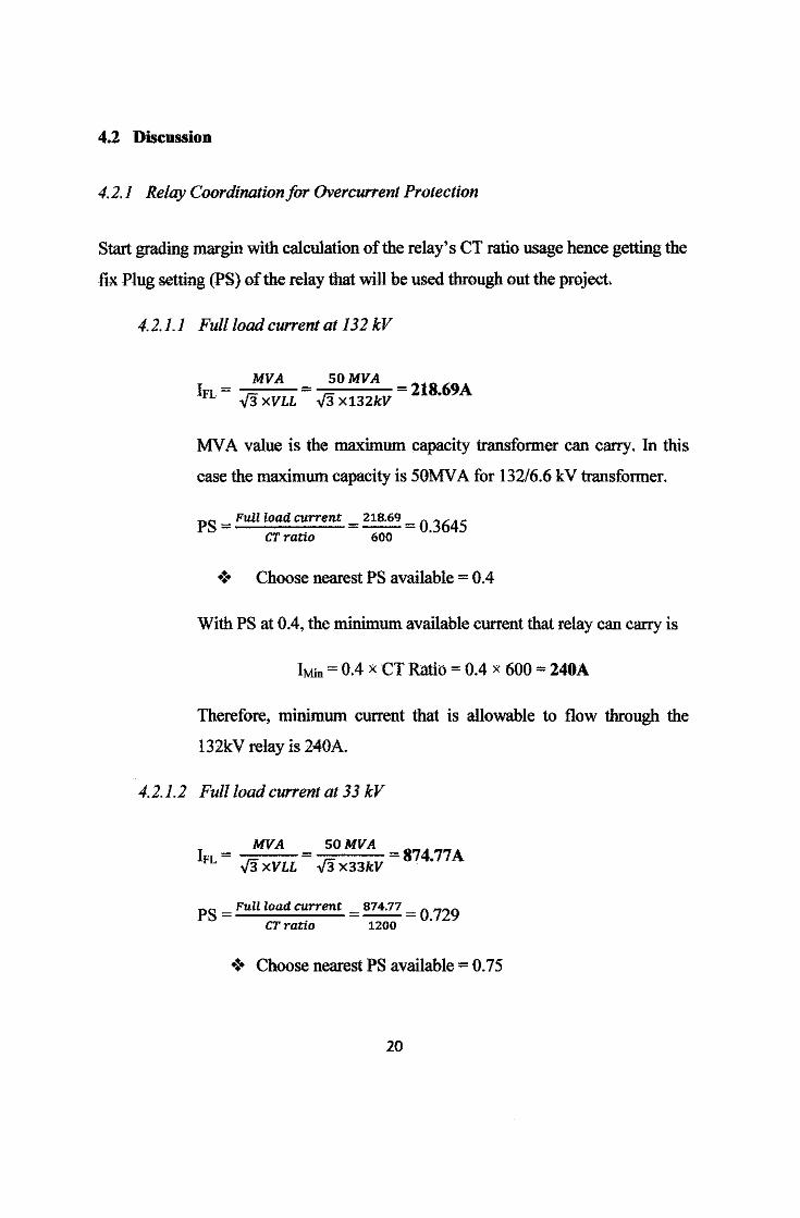
4.2 Discussion
4.2.1 Relay Coordination for Overcurrent Protection
Start grading margin with calculation of the relay's CT ratio usage hence getting the
fix Plug setting (PS) of the relay that will be used through out the project.
4.2.1.1 Full load current at 132 kV
MVA I - -=-FL - .,fi XVLL
SOMVA .,f3 X132kV 218.69A
MV A value is the maximum capacity transformer can carry. In this
case the maximum capacity is 50MV A for 132/6.6 kV transformer.
PS =Full load current 218.69 = 03645 CTratio 600
•:• Choose nearest PS available= 0.4
With PS at 0.4, the minimum available current that relay can carry is
IMin = 0.4 x CT Ratio = 0.4 x 600 = 240A
Therefore, minimum current that is allowable to flow through the
132kV relay is 240A.
4.2.1.2 Full load current at 33 kV
MVA I - -::::-
FL - .,fi XVLL SOMVA
.,f3 X33kV 874.77A
PS =Full load current 874.77 = 0_729 CT ratio 1200
•:• Choose nearest PS available= 0.75
20

With PS at 0. 75, the minimum available current that relay can carry is
IMin = 0.75 x CT Ratio"" 0.75 x 1200 = 900A
Therefore, minimum current that is allowable to flow through the 33kV relay
is 900A.
The same steps use to calculate other equipments rating such as at the second
transformer 33/6.6 kV transformer and motor rating. The result for the first
path for overcurrent protection as table below:
table 3: List of Plug Setting for Overcurrent Protection
Relay CT Full load Plug Setting Allowable
Ratio currenl (PS) current
IDMT 1-1 600/1 218.69 0.4 240
IDMT 1-2 600/1 218.69 0.4 240
IDMT 1-3 120011 874.77 0.75 900
IDMTcable 1 600/1 437.39 0.75 450
IDMTcable2 600/1 437.39 0.75 45()
IDMT 600/1 437.39 0.75 450
IDMT1 300011 2091.85 0.70 2100
IDMTBusbar 1250/1 1049.73 0.85 1062.50
IDMT 1 motor 125011 1049.73 0.85 1062.50
IDMT2motor 1250/1 1049.73 0.85 1062.50
21

4.2.2 Grading Margin for Overcurrent Protection
4.2.2.1 /DMJ' 1-2
;; .'·
T '
Figure 11: LocationofiDMT 1-1 andiDMT 1-2
Start grading the network from grid 1 for IDMT 1-1 for overcurrent
relay protection. The grid 1 is from PAKA132_M1 substation which has the
characteristic as below:
22

Table 4: Fault current and impedance for grid 1
Characteristic Value
3-phase current fault (A) 22 010.10
1-phase current fault (A) 25 757.50
Positive impedance 0.254 + j3.453
Negative impedance 0.663 + j3.774
Zero impedance 0.146 + jl.585
Given value for TMS and PS for overcurrent IDMT 1-1 relay as:
Overcurrent setting: PS = 0.4
TMS=0.2
Using the value given, we grade IDMT l-2 relay which is the relay after
IDMT l-1. The purpose is to find its Time Multiplier Setting (TMS). There is no
margin required between this two relay because there is no other feeder connected
to relay IDMT 1-l and we can consider it as relay in the same feeder. Therefore we
get the same graph characteristic for relay IDMT l-1 and IDMT 1-2 as shown in
Figure l2.
23

u lit ~ .. .!. l!.l :!: 1111 'f v.. "'~ 13 •• (
tJ X: !a Y:ll1
~ ··:: ·.: . . . . .
/ I
I A4,t•
;v~- -1-3 Fault
..
oooo r111 e ' ~ldallllirl Nlllk iJj ~ J Dcralir£ 0.394r fnshfm 0.394c
Tie 111!1M7 led; tali! 1111 ile ~ ci ~ p!iedm deW:es ~ llic ~ If yw select n ~ lhe 1owt n lhe ~. deYi:et « lhe clolen 11m ¥oi be lijijtednlheneld~rdnre~. nlhenetd ovavilw.IJrNdedlhat ilabes!.,led~ -
ISialul I• DeW:ec I ll Nd~ftlrd nlhefa.tpalh. 33 ..... __
N~ ~~ W n h fa.t pelll 0 Olan!l.aa,rd~becaae~'lttageiklobll 0 ~ 0 Op«alrY;j!U~... 0 Abolt ID opnle. W rd n fa.t Plf/l
lo ~ IJiliJI! 2 11 tija
Opseia eairtllage. w rd ilfd pall Opere! at eairtllaga CllliJI! 2a h!ils. Opere! at llllirliage lllliJI! 1 ~~~ ""'-CT Ia waled o
IDMT2-3 lr: 22.121 kA ~· 22.121 kA
IDMT-cah!e~ lb .".: 121 kA w :;( tl-!·~ ~ ~~ !n
:;( SB05-B02 !n
Figure 12: Result of Coordination Protection IDMT 1-2
24

Re ~ fl'!llil raj:h 1 ID:IDMT 1-2 Tme(s) Reference Vobge:131 kV
DeW:e: IEC255-SI 10' 2P
T _I_ CT A~~~ 600.0 Phase PS {Jll~ 0.4 Phase TM {Jll~ 0.2 l Ofbet 1.0
101 - -t -
raph: 2
I ID IOMT 1-1 Devu IEC255-SI
I CTR~(AH.OOO Phase PS !Jlll 0 4 10: --- --1 Pha$e TM !Jllt 02 OftsetlO I
101 _J_
-----<
10° - l t ------<
,2P
10., -------~
10,:·~---~---~------+-------101 10- 10' 10' 10; 10'
1: 3.995 (M), T: 12.374 {s)
Figure 13: Graph for IDMT 1-1 and IDMT 1-2
After grading, value for IDMT 1-2 relay are:
Overcurrent setting: PS = 0.4
TMS=0.2
25
Cu-rert (A)
I I
I! Frish !I

4.2.2.2 IDMI 1-3
For the second grading which is IDMT 1-3 relay, this relay is located at low
voltage transformer.
MT1-2
IDMT -cable 1
Figure 14: Location ofiDMT 1-3
Note that, we have to considered transformer damage curve in order to
design this relay. There are two characteristics that we have looked for to set
Relay's TMS:
1. Relay operating time must not exceed 1.6 sec which means the TMS value
can be increase until its operating time for relay is 1.6 sec
2. The remaining time must be less than 0.2 sec (since we only consider circuit
breaker time and safety margin which total up given 0.2 sec)
26

But for this system, we use the second characteristic since the value for
operating time is too small so we have to consider its remaining time must not be
less than 0.2 sec.
Therefore, value for IDMT 1-3 relay is:
Overcurrent setting: PS = 0.75
TMS=0.25
~ ·. - .. •.. . . . -
D ~ I • 1 ill ~ ~ ~ ~~~~00 ?
" X 413 V: 417
f.- ,:. .· . . ,. ) . r
IDMT-ca! c
Fault
lr: 6256kA
0 0 00 tit. • • Stage lrltJH:rl ttrabec [1 ~ d s o~ o.ns.
The_, lesW l.tle iils lhe ILllla d 4 ~ dM:el alh 11age.
I JW select one d h 101¥111 h l.tle. dM:es a1 fle c:lmen till,. be tioJ61Ied n 111enetMit ~in! an~. n lhe l'ollllllllk ~~'~~Mew. ~~i ha3bmqln:!ed~.
IStab Ji'D-1 NU ~ inlrd n fle fd Pllh 32 Nm~bintheldPBil o ! Dildinllll!iw rd CICIArG becue poleisalir) ~ i bl kM 0 i OpllaliiJ. 0 : Opeqq lilt NdecJIIIe ftlilgl\ 2 1A~x~.C~o~.hin:~~nldPifh o
AlxU lo ~Ill !0'111 . Operal!da~Mier -..hi n:~~ nfd Pllh
I' Opsal Ill Mill llage Ill !0'112 II t.;e. Opsal al Mier llage 111 !0'111. ,R.IIholeCT llllllall.laled.
0
Figure 15: Result of Coordination Protection IDMT 1-3
27
2-3
SB05-Bot
IDMT~
Re Ell Gr~
1 ... 1 10: IDMT l2 Tille (a)
DM:e: IEC255-SI 10' -CT RalnJ ~~ 1m 0 PhasePS {rA!tO.• PhaseTt.I~0.2 Offset 1~ 10,
~r¢ 2
JD· IDMT1 ·3 Dew:e: IEC2SSI
Reference VobGe: 33 kV 2P
CT Ra1nJ~P200.0 10: ----+----r----f-J----+-----t Phase PS [pJJ: 0.15 Phase Tlol ~ 0.25 Off!e!:lO
- -
10° -----+-----+---
+ +
I: 20.943 (IrA), T: 25.456 (s)
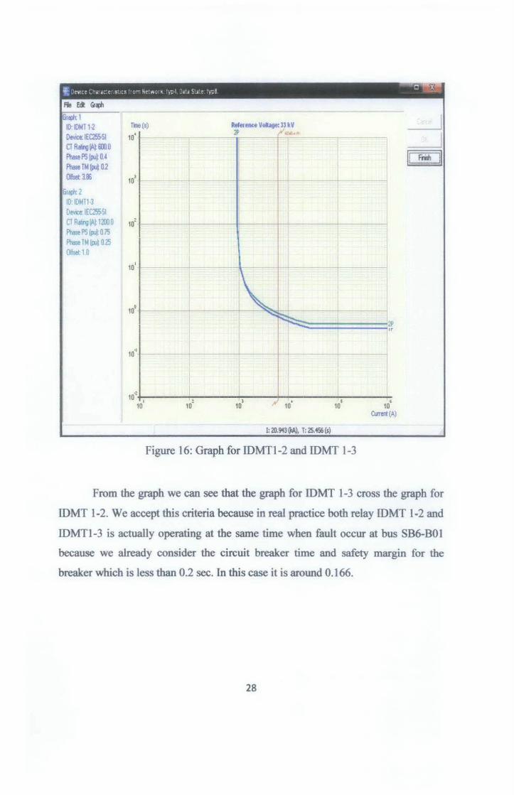
Figure 16: Graph for IDMTI-2 and IDMT 1-3
I! Frith II
From the graph we can see that the graph for IDMT 1-3 cross the graph for
IDMT 1-2. We accept this criteria because in real practice both relay IDMT 1-2 and
IDMTI-3 is actually operating at the same time when fault occur at bus SB6-BOI
because we already consider the circuit breaker time and safety margin for the
breaker which is less than 0.2 sec. In this case it is around 0.166.
28
to'
to'
to'
to'
to·•
to"' tO I to'
)
tO ; to'
I ••• a••~••-••-•••-•••••-•
I
tc1DM~<t!e2
~~ ~IDMT ~)'-J
DM'Gen~'' f~oM1 0
-
IOMTI-3 IDMT IWI!Illl-3 TR5AIIm oo tub.Y sa~m
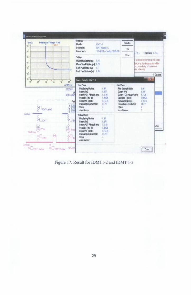
s~ F'ha!e 1\.g s~ w o. 75 Phase Tine J,l!J~ W 0.25 Ealh 1\.g s~ !PJ~ 0.1 Eadh Tinelol~fpJ~ 0.(5
Red Ph. 1\.gS~~ 6.~ Cu!n IliA~ 6.255 Cu!n I CT PN}I Rallv 5.2125 Operaliig Tine (s~ 1188526 RelllaiqTine(st 0.16616 P«ceetage Operated !%l 81 231 St.~u&: 4 ZnNI.IIk
Yehf'hale 1\.gS~M'* 6.~ CUTn IliA~ b.255 Cullri ICT PN}I R~ 5 2125 Operali-Q f~~~e (s~ 0.88526 Relllaiq Tine lsl 0.16016 P«ceetage Operated !%l 81 231 Slm: 4 ZnNII!ilef. 1
Bl.le Ph. 1\.g SdlilgMt.ti*; 6.~ CulertlliA~ 6.255 Cu!n/CT PN}IRallv 5.2125 Operali-9 Tine (sl 0.88526 Relllaiq Tine(sl 0.16016 PeJcerUoeOperDJI%]: 81 231 Stu 4 ZnNum: 1
Figure 17: Result for IDMTl-2 and IDMT 1-3
29

4.2.2.3 IDMT cable 1, IDMT cable 1-2 and IDMT
Margin for this IDMT -cable I with IDMT 1-3 is 0.4 sec since this relay is in
different feeder. But no margin required for next three relays which are IDMT cable
1, IDMT-cable2 and IDMT because these relays is in the same feeder.
I
~I DMT -cable2
¥ <t>i:JIDMT-1 .--------------- ':: = = = = = =:
~ IDMT -cable2 __ ..,._ sub-bus2
Figure 18: Location ofiDMT cable 1, IDMT cable 1-2 and IDMT
30

Fte Edt Gra!)h
Gtopr 1 10: IOMT1·3 Tme (a)
Device: IEC255-SI 10' CT AU>g lA~ 12000 Phase PS (pu~ 0.75 Phase TM (pu~ 0.25 Ofta11:10 10>
Gropr 2 10 IDMT -cablel Dew:e: IEC255-SI CT Ratrlg lA! 600.0 10> Phase PS IPul 0 75 Phase TM {pu~ 0 175 Offset 10
10°
Refetence Vollag<t: lJ kV 1P o=.o"
10"+-:-, -----:-. ----":"', ---!--:-------:-----~ 10 10- 10 10' 10' 104
Figure 20: Graph for IDMT 1-3 and IDMT-cablel
31
CUTert (A)
J II F"rioh II

The 0.4 margin required for IDMT 1-3 and IDMT-cablel result the graph
characteristic as Figure 20. The different at the fault current line for both of the
graph is 0.4 sec.
5ub-busl
IOM"'Gen
• 1r 6039kA SB5-C ¥ 6039kA
*'{] IDMT -mlle2
IDMTl
SB05-801
Slage~
N\nber :;-~ d 5 Du.iDt 0.46 I
The 11.n15J reds ~ t:a lhe llab d al ptUc~Jon de¥11:4 U JOJ teled one d il1e 10M il lhe ta!M. dM:es atllle craent ~nlhe~cb}"". andii'IDie~, n O't'el'/n,pDYi:led INi l tee been~~
,N<t~nlrdiltefdpalh 29 N<t~lx.tiltefdpalh 0
' ------------- ' DiedloM!IIIilllrw:t~becaulepolftalion~iambw o
~ 10Mrubfe2 Ops~ 1 )( sub-busZ Ops.rglx.t~,.. 3
AtxU" ~·' lx.t rdil fd path. 1AIJcU !D qJel& on Zlll1e 2CI t.ja
Opelllled a~ a-., lx.trw:tnfd ~ i Opsaled ala ~tag~ on zaw 2 e1 ho,tllll Opsaled aiNi!r atage on Zlllle l , Rei!Mrl whole CT tee laluallld.
lb 6 039 kA -blsbs ¥ ~ <HJIOMTI-bus~ S85-002 (jr{]~ ~ .. -... -- .. --- .. -- .. -- ..... ------ ... --.. ------- .... -.. _;_-_-_ .. _-_-_-_-_-_-_-_-_-_-_-_._-_-_-_-_-_-_-_-_-_-_-_-_-_-
Figure 21 : Result of Protection coordination IDMT
32
~ n ~x
"-: ~ "' " • ~ ... ... ··-- """ .. ~--; " .. ' .. , . --:: <.. __.. -
Fie Edt Gr"!lh td< I 10: IOMTI·3 Tioe(s)
Device: JEC251S-SI 10' CT Rairig lA~ 1200.0 Phae PS (puJ 0.15 Phae T M !Put 0.25 OlfMt 1 0 10'
~,'(it 2 ID IOMT Oe.-.:e:IE~SI
CT Ra1r1g IAl mlO 10' 1'1>= PS Ill<* 0 15 Phase IM!Ix4 0115 Oftl!l. 10
r4j:h 3 10' - - - -10: IDMT .c«JJe2 Device: IE~SI CT Ralrlg IA1600.0 Pheae PS lllul 015 10• Phase HI lllul 0115 Oftlll.lO
'(it' I[) lot bl
De. EC2'i5-Sl CT Rairig lA 1iOO Phase PS ta4 'l"i PhaseiM(Illt 17'i Otic« I 0
10..: I
10 J
10 10° C11nd(A)
u Frail n
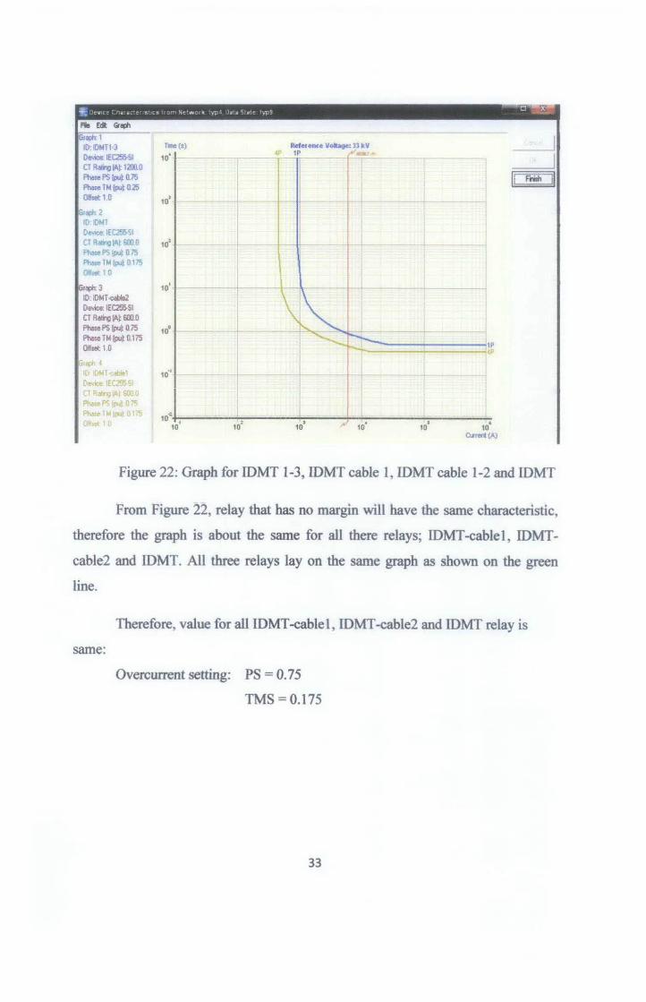
Figure 22: Graph for IDMT 1-3, IDMT cable 1, IDMT cable 1-2 and IDMT
From Figure 22, relay that has no margin will have the same characteristic,
therefore the graph is about the same for all there relays; IDMT-cablel , IDMT
cable2 and IDMT. All three relays lay on the same graph as shown on the green
line.
same:
Therefore, value for all IDMT -cable 1, IDMT -cable2 and IDMT relay is
Overcurrent setting: PS = 0. 75
TMS = O.l75
33
4.2.2.4 IDMI' 1
IDMTGen
>K c:>-D IOMTl-bu~
I ----------
885,{)~
~1-motor IDMT2-motor I
motorbus2
IDMT2-motor2
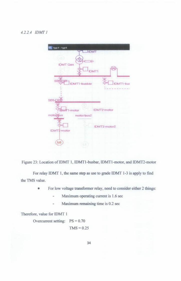
Figure 23: Location ofiDMT 1, IDMTI-busbar, IDMTI-motor, and IDMT2-motor
For relay IDMT 1, the same step as use to grade IDMT 1-3 is apply to find
the TMS value.
• For low voltage transformer relay, need to consider either 2 things:
Maximum operating current is 1.6 sec
Maximum remaining time is 0.2 sec
Therefore, value for IDMT 1
Overcurrent setting: PS = 0. 70
TMS = 0.25
34
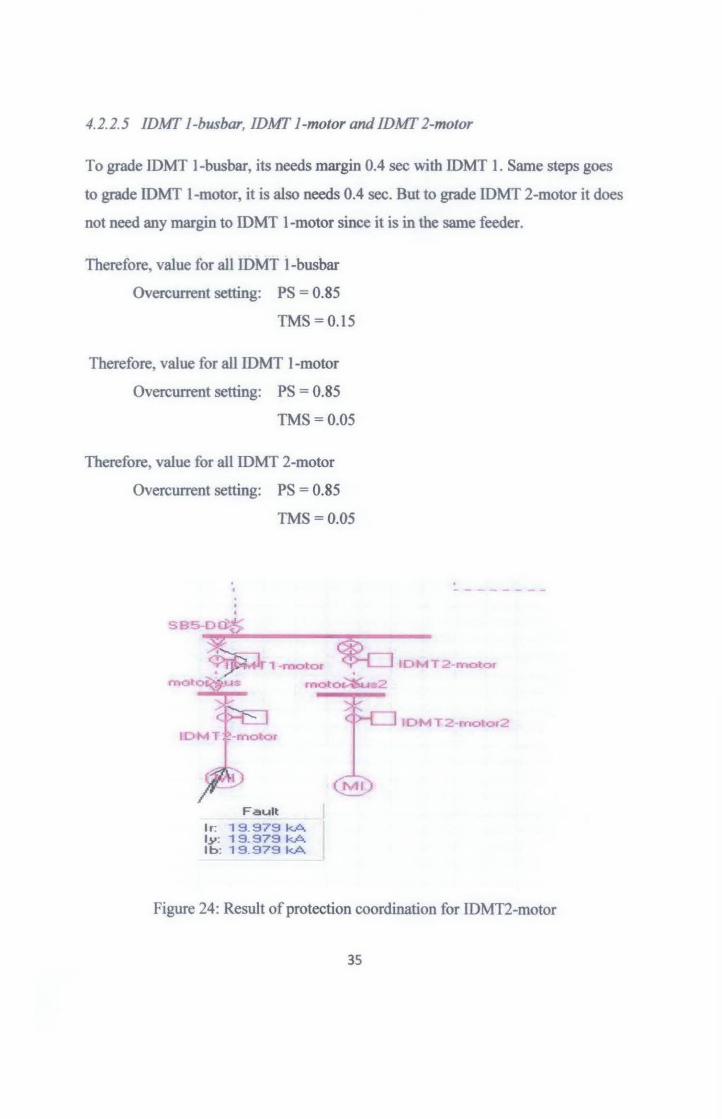
4.2.2.5 IDMI' 1-busbar, IDMI' 1-motor and IDMI' 2-motor
To grade lDMT 1-busbar, its needs margin 0.4 sec with IDMT 1. Same steps goes
to grade IDMT 1-motor, it is also needs 0.4 sec. But to grade IDMT 2-motor it does
not need any margin to IDMT 1-motor since it is in the same feeder.
Therefore, value for all IDMT 1-busbar
Overcurrent setting: PS = 0.85
TMS =0.15
Therefore, value for all IDMT 1-motor
Overcurrent setting: PS = 0.85
TMS=0.05
Therefore, value for all IDMT 2-motor
Overcurrent setting: PS = 0.85
TMS=0.05
. '
SB5-Dd~
. --------
, !~n-~oto< ~ IDMT2-<ne>t<><
moto~Ms moto~s2
Fault
lr: 19 979 kA ly: 1 9 _ 979 kA lb: 19.979 kA
10M T 2 -motor2
Figure 24: Result of protection coordination for IDMT2-motor
35
Fie fit Grllj)h
reph: 1 10: IOMT1-busbor Tlrl're(S) Refetente Vobge: U kV
Device: IEC2SSI 10' ~ ""''
CT Racilg !At 125110 I u !I Phaoe PS (pu~ 0.85 Frish Phaoe Tlol (put 0.125 i O"set 1.0 10'
I raph 2
l lD IOMTl·mo(a D~ IEC255-SI CT Rating IAl1251l 0 10' --- --+- - -- -- - -Phose PS !PJl 0.85 Phaoe TM (pul O.l!i Offl8l 1.0
'"""' 3 10
1 +
ID. IOMT2....m DoW:« IEC255-SI CT Rilling !At 125110 Phase PS (put 0.85 Phase TM (put 0.05
10° - --·+ -Off$1!1: 1.0
1P
10., -t I ~
I 10.,
' 10' ' • . 10 10 10 10 10
Ct.rrett (A)
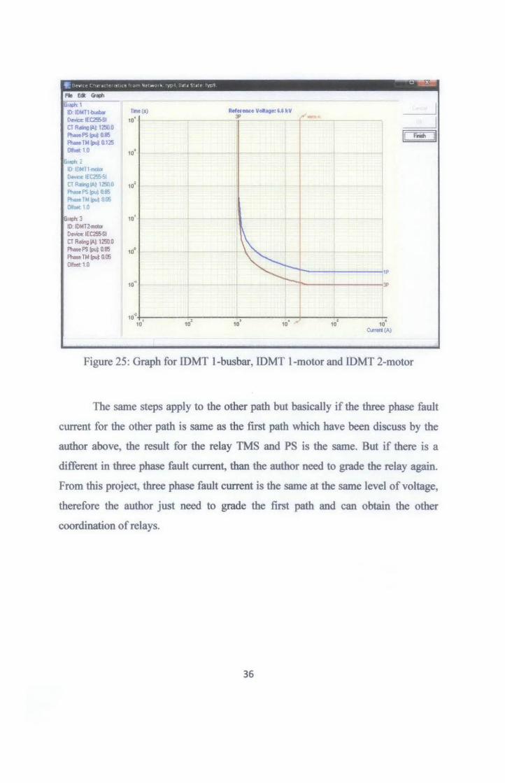
Figure 25: Graph for IDMT 1-busbar, IDMT 1-motor and IDMT 2-motor
The same steps apply to the other path but basically if the three phase fault
current for the other path is same as the first path which have been discuss by the
author above, the result for the relay TMS and PS is the same. But if there is a
different in three phase fault current, than the author need to grade the relay again.
From this project, three phase fault current is the same at the same level of voltage,
therefore the author just need to grade the first path and can obtain the other
coordination of relays.
36

4.2.3 Relay Coordination for Earthfault Protection
As in literature review, to grade relay for earthfault protection, need to
consider earthfault condition. Since earthfault always occur and to prevent its trip
on unbalanced load, the earthfault must be set 20% of its current carrying therefore,
it will operate faster than overcurrent relay.
4.2.3.1 Current at 132 kV
I= 20% X IFL = 0.2 X 218.69A = 43.738A
PS = Full load. ~rrent = 43.738 = 0_073 CTratto 600
•!• Choose nearest PS available= 0.075
With PS at 0.075, the minimum available earthfault current that relay
can carry 1s
IMin = 0.075 x CT Ratio = 0.075 x 600 = 45A
Therefore, minimum current that is allowable to flow through the
132kV earthfault relay is 45A.
4.2.3.2 Current at 33 kV
Ioc = 20% x IFL = 0.2 x 874.77 = 174.77A
PS = Pull load ~rrent = 174.77 = O.l46 cr ratto 1200
•!• Choose nearest PS available = 0.15
37

With PS at 0.15, the minimum available earthfault current that relay can carry is
lMin = 0.15 x CT Ratio = 0.15 x 1200 = 180A
Therefore, minimum current that is allowable to flow through the 33kV earthfault
relay is 180A.
The same steps use to calculate other equipments rating such as at the second
transformer 33/6.6 kV transformer and motor rating. The result for the first path for
earthfault protection as table below:
Table 5: List of Plug Setting for Earthfault Protection
Relay CT 200/o of full Plug Setting Allowable
Ratio load current (PS) current
IDMT 1-1 600/1 43.74 0.075 45
IDMT 1-2 600/1 43.74 0.075 45
IDMT 1-3 120011 174.95 0.15 180
IDMTcable 1 600/1 87.48 0.15 90
IDMT cable 2 600/l 87.48 0.15 90
IDMT 600/1 87.48 0.15 90
IDMT1 3000/1 418.37 0.15 420
IDMTBusbar 125011 209.95 0.20 250
IDMT 1 motor 1250/1 209.95 0.20 250
IDMT2motor 1250/1 209.95 0.20 250
38
4. 2. 4 Grading Margin for Earthfault Protection
The available values for TMS and PS for incoming 33kV /6.6kV transformer
is given by the plant supervisor to help the author start grading margin for earthfault
protection. The values are:
Earthfault setting: PS = 0.10
TMS=O.IO
This value is for IDMT-cable 1, IDMT-cable2 and IDMT. But refer to the
Relay Coordination for EarthfauJt Protection calculation, PS is 0.15. Therefore the
author uses this value to start with.
4.2.4.1 IDMT 1-1, IDMT 1-2
~ IOMT-cable2
*~=~
]IDMT 1 1
AlJl
SBOS-801
~
~T1·3 l IOMT-ceble1 )K >K >K
(i)....fl c:>-0 IOIV IOMT-ca~l ----- - __ <j>-0
0 0 0 ' ------------ - -----------------=-=-=-=-=--=~
~ IOMT-cable2 --..,...- sub-bus2
L=l,_- sub-buc;3 •
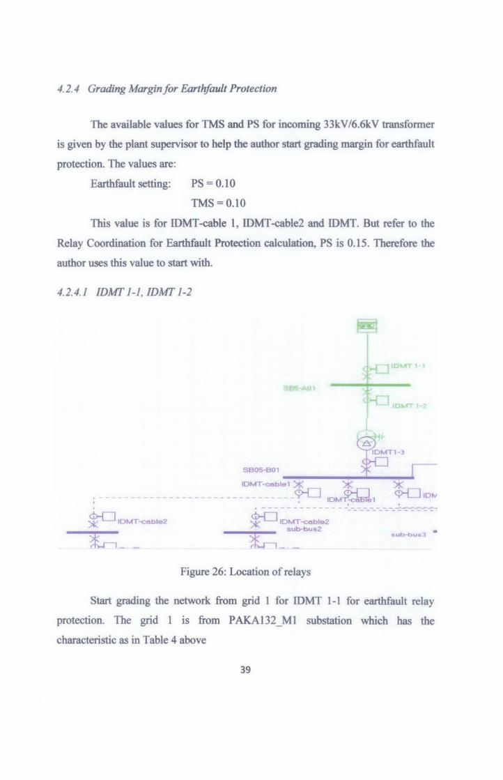
Figure 26: Location of relays
Start grading the network from grid 1 for IDMT 1-1 for earthfault relay
protection. The grid 1 is from PAKA132 M1 substation which has the
characteristic as in Table 4 above
39

The same characteristic apply here as in overcurrent protection. Since both relays
are in the same feeder, therefore it does not need any margin. The author set the
IDMT 1-2 TMS same as IDMT 1-1.
Earthfault setting IDMTl-1 and IDMTl-2: PS = 0.05
TMS=0.05
Fa.t ,, 32.511 kA tr nou lx QOirA
SEfU(ll -----.--_._,~~~·~
llMT~1)1: X ---······ ····· ................. m 10M~' ' ' I ' . -·------------.-,.,.-.----~---.~.-.-:.·· tollloll -atr2 ~ IDHI U:i1!2
~,~' ~~~ ~1 ~ t:
Figure 27: Result of Earthfault Protection Coordination for IDMT 1-2
40

Fte ~ (#~ ~·
10: IDMT 1-2 'lnll (l) Pdetence Volbge: 1J2 ~y
De-nee: IEOSSI 10' 2E
CTA~~600.0 E.v1h PS lpul 0.~ II frilh II E.v1h TM fplt 0.~ oqae~: 10 10' -- -- -Gr~2
ID:IDMT 1·1 Oew:e. IEOSSI CT~Io\!600.0 10: + E.v1hPS 1P4 0.~ E.v1h HIIPJl 0.05 Oftaet 1 0
10°
10°
., 10 2E
10·:
10 '
Figure 28: Graph for Earthfault Protection for relay IDMT 1-1 and IDMT 1-2
4.2.4.2 IDMT 1-3, IDMT cable-1, IDMT cable-2 and IDMT
The problem occurs to grade relay IDMT 1-3, IDMT cable-1 , IDMT cable-2
and IDMT. Note that earthfault protection for relay located at low voltage
transformer must be grade with overcurrent relay located at high voltage
transformer. For this project earthfault relay IDMT1-3 must be grade with
overcurrent relay IDMTI-2. Therefore the author uses this characteristic to grade
IDMT 1-3.
41

10'
10'
10°
10°
10.
10 .. 10° 10' 10° 10
s.wo "'-Pl.vS.VW 0.1'5 P~~Mr ... .....,..w a.2!5 E..,P\.vS.VW 0.1~ [..,T.,...,.._P¢ Q3 o oo o 11a • •
S~.,gti-N.....,. jl- :1 d 1 0........ O.Oo fnoltT- O.O o
Tho_J_.,Iobloloblho.....,ololpCiioclionciM;a"'u-Oo-lf)'CIU- ... ollho-illhoi.t>lo.-lllho--.. .... bo ~;, .... -.s.g-.rd-.~ ..... ---~lholthoo-~~.
5I.. I• o..c. r- 1Nal-.rQrdN:II•hfdpolf\ 32
~---......... ~ )( )( _ .-.... .. ,.,.~-~ ............... 0
- - - - ----- fd
¥3 IOMI ...tlo2
(!;.("1 <x...J • ~ 0 IDNf.~t , ·OpHrvw~- D
·-..·.·.···· '""':'- :-.ID-•.Wnclnlajpolf\ 0 , ........ _ ........ 2 .. hdw 0
to~' .. ......... _. ....... ,. 0 'Opor*<l .. -ologo.Wncl,fdl>lfl, 0
10por_ot_o~ogoan ... 2Gh:!#w 0
,lljool*<l .. - .......... 0 e Relo!:M _ cr hoi ... -. o
k D-i-Tol:lo l~
Figure 29: Result for Earthfault Protection for relay IDMT 1-3
Refer to the Figure 29, the single phase to ground fault current is too small.
The current is just 17 A and the IDMT 1-3 relay cannot detect such a small current.
This occurs because of transformer connection. Transformer 132kV/33kV
use star-delta connection with solid grounded at star side. The star side connected to
the supplier which is 1NB while the delta side is connected to the load. Other than
that, delta-star connection is use for transformer 33kV/6.6kV. The delta connection
is at high voltage side which is connected to the delta connection low voltage side
132kV/33kV transformer. Therefore the unbalanced current is circulating around
delta connection and not returns to ground. While this happen, the supplier which is
1NB cannot detect this unbalanced occur.
Therefore, relay at this path which is IDMT1-3, IDMT cable-1 , IDMT
cable-2 and IDMT only can detect if there is overcurrent occur not for earthfault.
This may risk the plant while operating this relays.
42

Fie fdt Graph
roph 1 10: 1Dt.H·cablo1 Device: 1EC25&51 cr Ra111g IAl 600.0 EorthPS!po.dll15 Earlh TM [pu~ D 1 0111et1.0
-c. C) &. •••
St..go lnformalion Number. r ::J ., , Durolion: 0.0 • Froilh Time. 0 0 s
The summary reaub t"bl" 5sts tho otatuo ol "I proteclion devices et thia otag10. If you select one ol tho row a in the table. devices et the chooen slat us wil be ~in lhe networl< ciagrarn. - """"conveniently. in the network overview. provided that l hoo been~ ..JfiCientlv
Staluo
Not operating - not in h faul pelh. Not operating. boA in lhe 1- pelh. 4 Directianal ,.,._not operating beoet.e ~ vo1t<v> ia too low. 0 Operating. 0 Operating boA inodequeto rnavri 0
SB05-B01 AboU to operate. boA not in, .... path. 0 --------t AboU to op«ale on""""' 2 or higher. 0
,,...,,, ...,... -"'"" Opereted et earlier at-. boA not in, .... path. Operated et....,... ol- on zone 2 or hrltler. Opereted et earlier at- on zone 1 Rele}(s) ..nose CT t- •at<aated.
Figure 30: Earthfault current at Cable 1
Time l•) 10• 'u.a • 1E
10'
102
10°
10°
10. ,
10 .. 1 I 10:
Figure 31: Graph for Earthfault current IDMTI-cable
43
i .. ~ 0 0 0 0

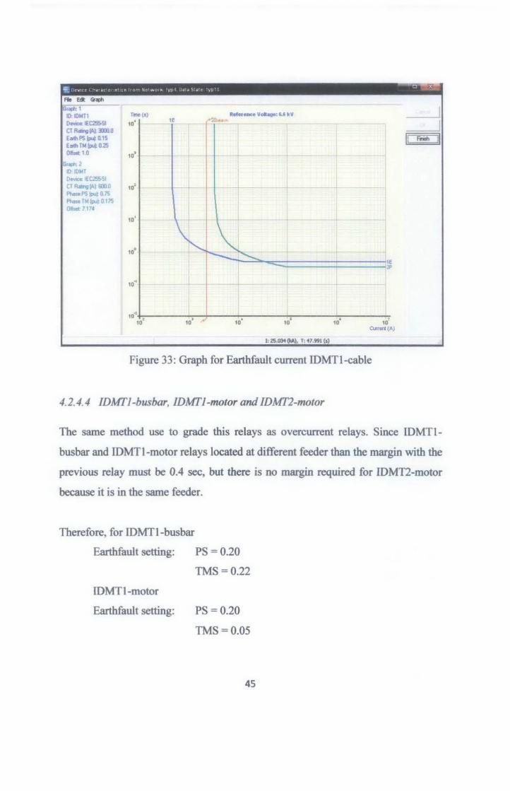
4.2.4.3 IDMI' 1
IDMT 1 relay located at low voltage transformer, therefore it must be grade with
overcurrent relay IDMT. The result that we have as Figure 32 and Figure 33.
We can see that from the graph, the earthfault line never cross the IDMT relay
graph. The author set the TMS value so that it meets the requirement for the next
relay to operate.
Earthfault setting: PS = 0.15
TMS=0.25
o,......., 1 07 a Frioh T"""' 1.07 a ···--·-----------------------
lr 2.2491<A iy OOkA
. ttr O.OkA
'
~~- ~IDMT2<nelol ~ ~
To ~10w•
The "'""""')' <edal..ble bts lhe al.otua d ol prcUcbon deo;ices II .ria ~~age. II )IOU .elect one d the lOWS n the table. deo;ices Ill the chooen ll.alua will be ~in the nol-k Oagllll. and mole~- in il'e nolwok .,.,._,provided thai in.'-"~ d ........
0
0 ---- .:__ 11 __ }
Operaled Ill ellier Que. boa not n ld polh.
Operaled Ill en. uoe on zone 2 ar hV>er Dperaled at e11ier Que an zone 1. A~a)......,_ CT hetlltlllled.
0 0 0 0
Figure 32: Result Earthfault current for IDMTl
44
596
Fie Edt Graph
raph: 1 10: IOMTl 1n (s)
Ofl'¥ica IEC2SSI 10' CT Rating IAl Dll.O Eslh PS (pu~ 0.15 Eslh TM (pu~ 025 Ofla«:10 10•
,.., 2
10 IOMT 0""""" IEC255-SI CT R*'!I!Al 6000 10' Pllase PS {pu) 0. 75 F'haoe TM (ilul 0 175 OHsol: 7171
10'
Refetence Volloge: '-' kV 1E a ••
r ---,---
1: 25.03i (IrA), T: 47.991 (s)
Figure 33: Graph for Earthfault current IDMTI-cable
4.2.4.4 IDMI'l-busbar, IDMI'l-motor and IDMI'2-motor
__j
u Frilh II
The same method use to grade this relays as overcurrent relays. Since IDMTl
busbar and IDMTl-motor relays located at different feeder than the margin with the
previous relay must be 0.4 sec, but there is no margin required for IDMT2-motor
because it is in the same feeder.
Therefore, for IDMTI-busbar
Earthfault setting: PS = 0.20
TMS = 0.22
IDMTl-motor
Earthfault setting: PS = 0.20
TMS=0.05
45

IDMT2-motor
Earthfault setting: PS = 0.20
sub-bua1
SC5
Foult l r 2Z48kA ly: 0.0 kA It>- 0 OkA
TMS = 0.05
St-lnlonnatJOn N....,..,_, f1 - of 3 D uration: 0.&23 c Frioh Timec 0.&23 •
Tho ...........,y raaA• toble r.ata tho • t<ALU of ol protection dov;cee at this at-. II .I'(IU aolect one o f tho row• '" tho toble. dovices at tho chosen statu• will be highlighted n the nelwork diogram. and more conveniently. '" the n e twork ovennew. provided thai it na. been e>epanded sufficientlY.
Status Not operating and not in the foul path Not operatJng. but In the foul .,..._ _..;.a.;.._... Dnoctional rato&o not -aling becauee polenaotJon voltage ia too..__ 0
Oporellng but r-tequate ,_gin_
About to _at ... but not in fault path About to operate on zone 2 or 1-9-Aboulto -ate on zone 1 .
!--~~-~ Operated at_...--- but not in foul path.
Operated at eorlief • - on zone 2 or~O porotod at ....,.,. •- on zone 1 A~al who- CT na. aaturoted.
0 0 0
0 0 0 0
Figure 34: Result IDMTI-busbar for Earthfault Protection
46

- ..... - )(' T: .. • • • • •• ~ •. - •• ' •. ·'
"" Edt Gl!>h laiiii1 IO:ID~Tl o....,.. IEC2S&SI CTR~~tlWlO Ed PS (pul 0.15 Ed TM (pul 0.25
1 o.-1o ,Gr<dl 2 I 10 IDI•Hl-lluoblr
Oeva: IEC2S&51 CT Ratng lA} 1250.0 EdPSW 0.2 EdTt.I(Jlul02 Offset 1 0
~1
Tme(a)
10' 2E 1f
II ..... II 10'
10:
10°
10°
10.1
10" 10° 10:
1: 962.'19 (A), T: 12163.1 (s)
Figure 35: Graph for IDMT 1 and IDMT 1-busbar
S tage lrlormalion
N...,.._ fl :i ol 3 o .. a~~on: O.lSSs
Tho ....,.,..,Y .-Ala table iota the atatua ol al protection r:lrwic:es 61 this atage If you ael!ocl one ollho rowa ., lhe table. devicM etlho c:no-. status will be hg~Wgtlled 1n the netwook ciagr-. and tn01e eonvenienlbl. in tho network OYeMew, provided that t hoa ~ expanded wffic:ient!y.
~talus II• OeW:ea 1 Not opera~ng and not in lho , ... pelh. 26
Drec:tional r~ not operebng .__..., poloriaalion ...,._ ia too low 0 I Not operatng. W in the ld path 6
OperaQno. 2 Operatng W inadequate mwgin. 0
585-0~
~10M T1 -bu:bar
sa sod.~
~ ' '
lr. 2.164 kA ly OOM lb: O.OM
'\..:Y
IDMT 2-motor
101>4 T 2<f110t012
!Abo<a to operate. w not in, ... pelh. 0 iAbo<a to operate on zone 2 or tV>er 0
Opereled et-"" ~- W not tn faA pelh. Opereled et-"" ataoe on zone 2 or tV>er Opereled el-"" stage on zone 1 R~s) whose CT hoa catu'eled.
0
0 0 0
a Hode,i""""*)' hble II Qose
Figure 36: Result IDMT1-motor for Earthfault Protection
47

~~ 9; ("\I l- • o1 ,.. "' "' ht"' -" 0\ ¥":. • HI • '-!.o't"' \(t • --
Roo Ell; Gtoph
rapk 1 10: IDMT1-bo.nbor Device: IEC255-SI CT Ramo~l12al0 E orlh PS (pu~ 0 2 Earth TM (pu~ 02 Ohoet 1 0
raplr 2 IO:IDMT1rnota Oevrco IEC255-SI CT R .. ing ~~ 12SO.O E.U. PS !Pul 02 Eortn TM ll>Ul 0 05 on~ 1 o
Tine (S)
10'
10'
10°
~ __..:~ (:!:"" ....
l l t
10'·+:------~------:-+-----:--------:-----~ 10° 10' 10
1 10' 10
1 10'
OlreR(A)
1: 33.118 (l<A), T: 13.961 (s)
Figure 37: Graph for IDMTl-busbar and IDMTl-motor
Stage lnlonnabon N.m-: r- : o/ 5 o ... otion: o. 159 • Fonosh TOne: 0.159 •
The summary redo table liato the atatuo of all poolecbon deviceo at !hit olage.
II you select """ olthe rowt i'l the l6blo. de~ at the chooen •letuo wl be higlllig,ted in lhe nelwotk diagram, and,.,.,... c:onvenienlllo. i'l the network o.......W.W. provided 1hat ~ has been eocpended sufficiently.
__ j _]
II Fnoh d
Statuo -------.....,.~-:---..
SS!:>-0~
~1-motor to IOMT2·""*'<
....,tc •• ~~.. ...~
T r~'~' Faul
lr. 2.1SolkA ly: O.OkA lb: 0.0 kA
Not ope<aling and not i'l the faul path. Not ope~oti'lg. but i'l the faul path.
- Diec:lionool rel<oy not _.aling becauoe pol..n.ation vall- ia too low 0 Ope~aling. 2 Operating but~· ma~gin. Abo<A to ate. but not in fault pa1h.
IAbo<A to ope<ata on zone 1 •
Ope~"'ed"'-·-·but not in fault palh. Opereted et -"" .._on zone 2 or higta'.
Opereted ot earliet ~~-on zone 1. Aelay(o) whole CT has -.eted.
d Hide£~ Table II
0
0 0 0
Figure 38: Result IDMT2-motor for earthfault protection
48
'f; I C""' ~ • • ~ '" ,. "t~ .,., -' • y:. " • ~·. ,.. y': •
Fte e.- Ciraph
r.P,: 1 ID: IDMT1-buobar Tme(s)
DIMeo: IEC255-SI 10' CT A '*'!liM 12&1.0 EllfthPS (put 02 Ellfth 1M (pul 0.2 OJJMI: 1.0 10'
r.P,: 2 ID IOMTl-rno!OI Davrce. IEC25'5·51 CT Flaln;IIAt 12&1. 0 10' E-'1-o PS (pu) 0.2 Elllh TM (put !l05 Ofttt't 10
r.P,: 3 10° ID: IDMT2-motar DIMeo: IEC255-SI CT Roq lA~ 12!i0.0 Earlh PS (pu~ 112 10° + Earth TM (pu~ 0.05 Offoet 1.0
10.1
10" 10
1
Reference Volto~: 1.1 •v ....
--+ - -
1: l0.613 (1<A), T: 196.19 (s)
!,'~ )(
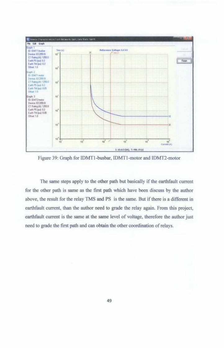
Figure 39: Graph for IDMTl-busbar, IDMTl-motor and IDMT2-motor
The same steps apply to the other path but basically if the eart:hfault current
for the other path is same as the first path which have been discuss by the author
above, the result for the relay TMS and PS is the same. But if there is a different in
earthfault current, than the author need to grade the relay again. From this project,
eart:hfault current is the same at the same level of voltage, therefore the author just
need to grade the first path and can obtain the other coordination of relays.
49

CHAPTERS
CONCLUSIONS AND RECOMENDATIONS
5.1 Conclusions
This project, basically study on current protection coordination at GPPB.
Main objective of the project is to do grading margin for overcurrent and earthfault
protection from the source-TNB to the high voltage system is 6.6 kV motor so that
it meet all the requirements (stable, selective, sensitive, fast and reliable) to operate
safely to human life also to the other electrical component. For overcurrent it
related to 3-phase current fault and for earthfault it is related to the single phase to
ground fault. Both current faults needed in order to grade the relay. The best
coordination need to be find by getting the Plug setting (PS) and also Time
Multiplier setting (TMS) for the relay. These two components is a setting of the
relay to determine time for relay to operate. At the end, the coordination for
overcurrent and earthfault can be achieved
The author finished design the network inside ERACS software for high
voltage network and finished design the grading margin for the first path. While
doing the grading, the problem occur where the given Plug Setting (PS) and Time
Multiplier (TMS) value by the plant supervisor is too small and some consideration
such as:
1. Consider the maximum remaining time is 0.2 sec for relay at low voltage
transformer
2. Relay for bus that have only one feeder no need margin
From the result, the author cannot compare TMS and PS value with the real
value use at plant because the author cannot gets all TMS and PS setting values. But
50
still with the available value, there is different in PS value calculated and real use at
plant for earthfault protection relay.
A lot of lessons that the author learnt from this project which cannot be get
in class. The author learnt the steps taken to do grading margin, some characteristics
that need to be considered while grading, and learnt the usage of ERACS software
as one of the software use in Power system.
5.2 Recommendations
There are some recommendations that the author would suggest to be implemented
and corrected for this project:
I. Refer to the Relay Coordination for Earthfault Protection calculation, there
is a different in PS value for IDMT -cable!. The value should be 0.15 for PS
rather than 0.1 for PS use at plant.
2. The use of star-delta connection at 132kV/33kV is not suitable because the
earthfault current is too small at load side. The relay cannot detect if there is
earthfault occur and can only trip if the overcurrent or three phase fault
occur. The author suggests replacing the transformer with delta-star
connection
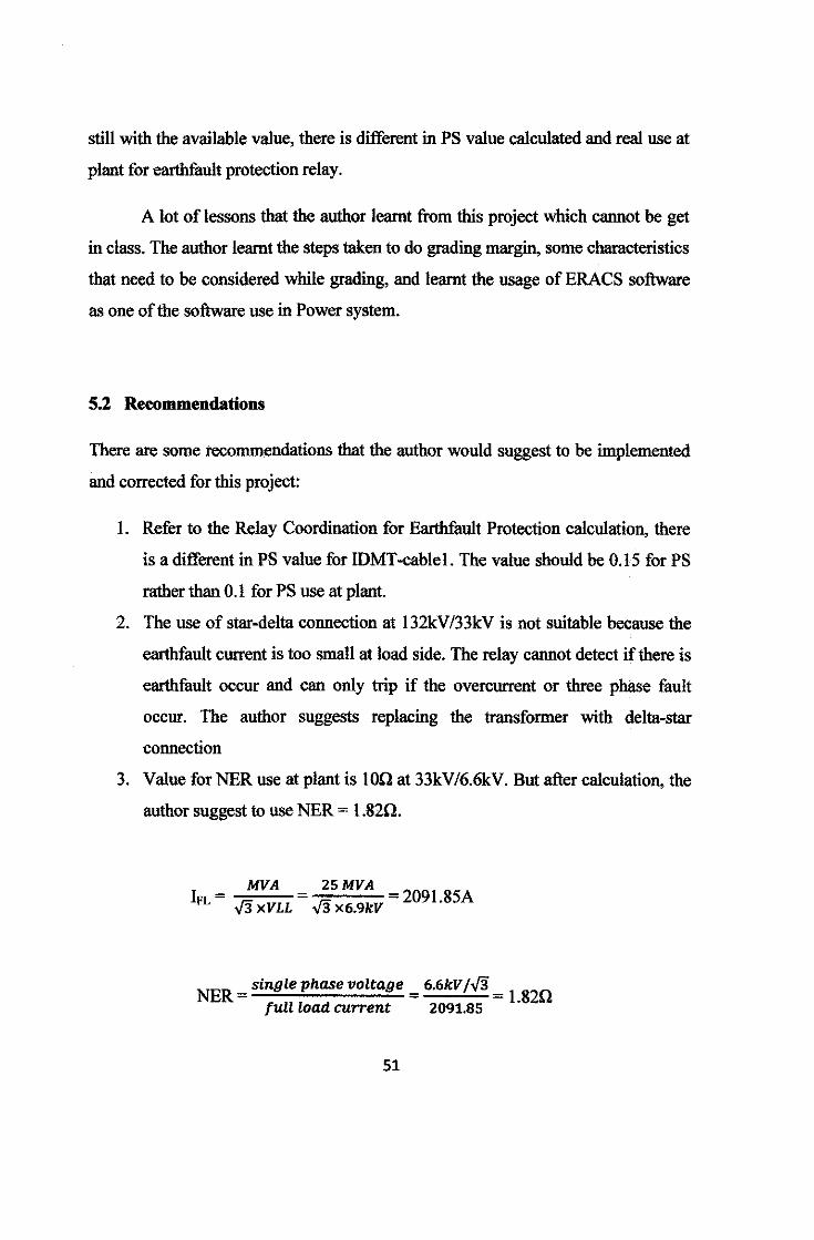
3. Value for NER use at plant is 100 at 33kV/6.6kV. But after calculation, the
author suggest to use NER = 1.820.
I _ MVA FL- ../3XVLL
25MVA ../3 X6.9kV = 2091.85A
NER =single phase voltage full load current
51
6.6kV f../3 l 820
2091.85 •
REFERENCES
[l] /EM Professional Interview Report, Protection Relay Coordination and
Protection Equipment Commissioning Testing of the 22KV Main Switch
Station (SSU) Satera Maju Project, Tenaga Nasional Berhad (TNB) Ipoh,
Perak.
[2] Hadi Saadat, Power System Analysis, Second Edition. McGRAW-HILL
INTERNATIONAL EDITION, Electrical Engineer Series.
[3] John J. Grainger and William D. Stevenson, Jr. Power System Analysis,
McGRAW-HILL INTERNATIONAL EDITION, Electrical Engineer
Series.
[4] A Guide book on Distribution Protection - Coordination of Protective
Device from Tenaga Nasional Berhad
[5) Distribution Protection System note by Unit Perlindungan (Kedah/Perlis)
Tenaga Nasional Berhad.
52

Appendixes
53
......,, 131<l.433 kV n~ SOkVA f -.::::~1 I -% -
=O!Jgoi'w
~ g
I
I SB5-AOII
i~~~l~ m-U-;Ut·" ]g'~jtn i"-'-ConlroiPIINI: II~ !~---~-! • - - - "J g,.~50A m> .... ..., ____________ :------·--: ___ :;_~:::,, _;_< ~
11L _ _., 1 ':,;.! .-' -"·' 1250A I I• •:$ I ~ToEICS
------::.1
To ElCS
EOOIIA ' J
FOR PROTECTION ANO"METERING SYSTEM, SEE INCOMNG CIVERtieAD UNEFEEOERNO,t
·•f--/d if~t"' .,
·•!--'""" ' ' J I SB5-A021 132 kV- 50 Hz.~1250A-31.5 kA3s ~---'/ l - \1
1b TR5-AB02
i -
SBS-E02
/ 1 125llA - ~'"OA I -= GCB L~ \ N.O olr-- · _I
7 12~A ~1250A
·•I-"
-""""-,---------] 1250A 1®88: ' GCB :!OJ88! ~-"·" l--:··-:----'
~
ToE!CS
)l'oEICS I j t
t
lbEICB (-
ToEICS
·:--
,~1 ToEICS
! ~ • ~-------, )121Xi'1A III'I"D< ~ ~ ~ ~! ~! u • ,,.. i =•v<J ;lAMP _______ j ~---~-i-i-~ ~i.
GCB N.C
TR5-AB02· ~ 13:2134.2 w 1 40150MVA Orum/Onaf Uec=:12.5%
[;;~]::::: :~1;::::
To EICS
FOR PROTECTION AND METERING SYSTEM, SEE 'fRS.ABO'I TRANSFORMER
"'"''
., ----- --) TR-BE02
~ ·--[o;;;J Deoo:llllrtet.:l<Rt
G;] ........ ,.,. -[':ji] IDMTO.....C~m..t
~ IOMT&thRdR
6iJ --"-'· ... ~ ,_,_..., B DirectlanoiO..Cu
G] Trip~Rt
l5lJ ·--15'1 """"-ll<'iJ Jlao~R~
[.;.;J ~&thF• /.LVSdo
~ .... ,_., Mlllfn!UBor1
~ a.. Bor PI<Ucim MillnS..8ar2
~ Buollllr~Zonl
® -@ -8 , w•t.~~ter
9 ... ._ ;;;] ' Seleclor91rich-(\ol
[\jJ 'SeloclorSIMII:h-l,k
e '~o.n.rtrl
9 -Fa ... -1""~;;""-:"'!i• ;.;,;.;~ ____ . _rr;,;-,:;~;~ '¥!'
1 ,-;: u~ [ ;··--- -~~~~~~~--------:--~/
:::r:::f=~=l=s~B=5=-B=0~l=l~~:•:v:-oo:~~-=,2:oo:AF·2:•~~:•·:'-:--:-:--:--~~===t~~=l· ---F::==~·==-~~~:I::~:::i~~-~~-~~==+===~l~s~B~5§-B~0~2~1:: ....... ...........
Equipped ..... '
TOGPPS Feeder 1 To EICS
As GPP 6 Feeder 1
~
ToEICS
ToGPPB Feeder1
As GPP 6 Feeder 1
*V : V~stgnaJa. fnHn Incoming vr. via elrcult bmlaker auxBiary switches to. identify switching cenflgunttlon
SINGLE UNE DIAGRAM 132 KV MAIN SUBSTATION PROTECTION & METERING GPP 5&6, TOK ARUN DRAWINGNO: 02
S8ssd Or! D"aMng No 05d120061-09

15-DOI I
50kW 'lrterpump
<750kW
ENGINE PANEL
~===1=:.n ~i SYNCHRONIZING
SECTION
I' b~l"·'' ~I "1110000 CD CD fl. 1+>1--"'l.....-~ = ~
® ® 88
®[l§]i)(l _ro.;;l.,
~
I
TR&-BD-01 3316.9 kV 20125MVA OnanfOoof Ucc=8% Taps +I· 2.5% ,5%
I VobQO-"""' f---a.-vro .... ~ l """"'-""' l I,
L~"' I -I' GENERATINO SET CONTROL PANEL
' ToEICS
6.6 kV, 50 Hz·2500 A
:::_: ToEICS
400A
1250A VCB
vcs 630A - ..-----,
e s kV 2;::L )I SBs-oos I
750 kW ·3'.5 MW
i i To EICS To EICS
! i i
From 33 kV SB5-B07
BusbarA
,,, ~·· ~
ToElCS
~
L-====r=l~F,Jl-, ' 'il' I~ ,, •
lf VCB '
,,
~·
.. j. ' ···ToEICS I i
··'""'""""'""'~~'·
t,fT~ il ~ ' ~ ~~ F!~ AT8-001 Typical
~""""' Feeders to (OPCU3)
TR5-DE-21
I ATS-051 '
TR5-DE-31 (GPP516 Utility) '
TRS..DE-418 TR5-DE-61
Spare (GPP5/6 Utility)
TR5-DE-91 (ACS)
(REfER TO TRS-DE-11}
2500A VCB 52AB N.O
" ;11{;1250A
VCB
•I' r:····•\
:-.-' To EICS
[S8s.OO. I Outgoing CircuitS
From
TR5-B0-02 am.ekv 20J25 MVA OnanJOnaf Uoo<8%
33 kV sa5-B06 -· Taps +I· 2.5% ,5%
'1 c®
-·· ,,c-,--t-1 ~
' lr Typical
Feeders to -:l -~ TR5-DE-32 (GPP516 Utllty) TR5-DE-42B TRS..OE-62
I (GPP516 Ub>ty) ..... (REFER TO TRI-DE-11}
~
,_ ,. I For Protection And Met8f!ng System, see TR5-B0-01
I SB5-D02 I
A 1250A \. VCB
"-----ll
0 ToEICS
. 1<'""1 -~ • E3J -·· ~
,_, -[5;] IDMTOWrCu'rlll
~ IOMI" Ellth FU
G;l --"""""""' GJ T~~R 81 T~Relay
~ ...... _.
l"il LJXt< out Relay Fe _ ... ~
,_,.. -~ --· ~ ......., ...
~/LV.olo
r;;;] ,_ EariiiFIUIR*i
~ T .... l!:tmo"DIJII -[::;;;] -----B FiefljFai>ftR'*
['];] OvliriUmrF~UqJ -~ Nogotiva~S
''" ["';;] ,.._,_ L:J ObfeFIIilnRW
Q --~ , __
[::;;;] ,:r"QhldTn
~ .......... ~ -~tmrlzi
® -· @ v•-Q --" SeloclcrSWtd>·f
'" --~ Gl ---Gl l<ioWaiiHol.o"""' --As Switch Board 885-005
[ SBS-004 I Outgoing Circuits
As Switch Board 585-003 il ,..,
TOEICS INTERFACE PANEL
•
r :sBS::iiii 1
SINGLE LINE DIAGRAM PR01ECTION AND ME1ERING GPP5 SUBSTATION GPP 5&6, TOK ARUN DRAWINGNO: 04
Ball8d On Orswlng No 06&'15120110f..06

·1901 KV tiNA =9.7%
B6-DOI I
ISOkW ..,.,_
ENGINE PANEL
TR&-B0-01 33.15.9kV 20125 WA OnaniOnBf
""""% r··--···----------------1
i-----0 I """"'"""" Taps +/-2.5% ,5%
l ·~~·"""" .. . . I '.. . • I l I
I ~==--a.i~ ... I <'IW!a._ ....
I __ , ,--;;;;--,1
; <:) o 1 c._::::'_j J ; \: GEHERATUG BET CONTROL PAHB.
ToE!CS
,-,
'"' To EICS
6.8 kV, 50 Hz~2500 A
1250A VCB
I I
'""" 33 kY SB$-903 BusbarA
~----
"~- - l .• I
T
, _ _I ____ 1 -~ f __ 'o'"' f - -1 I
~Jis :::l h d ~FROM
1
! ' VTBUSIIARS Typl~ Feeders to
TR6-DE-21l ri-;AT"-s-os="t------~ 1 ATS-001 (DPCU3)
p,;:oo,- I
<750kW 750kW-3.SMW
f8B6-liill
To EICS To EICS
l i i
TPR
TR6-D&. 31 II (GPP516 Utility) TR6-0E-41 I TR6-DE-61
Spare I (GPP6 Utility) TRS-DE-92 (ACS) TRS...OE-41 (ATS.D41)
(REFER TO TR&-OE.11)
'""" INTERFACE PANEL • ::r;.u ~ ~~~I I .... i I cr::J I 'o""
4!5V I SB6-EI2 I
'0""" ~
TRIS-B0-02 3319.lilkV 20/25 MVA OflaniOnal' u-.. Taps +I· 2.5% ,5%
'""" 33kVSS~ ..... ,.
,_ ,
I ~ f''"~ S~Ct.l
I"3J --Q] ·--~ -['=i] ICMTO...C..,..,.
[:;;_) IOMTEorlt\FdR
[5;,1 --0\oii"Curen!Rrta)
[;] Tr10~RI
81 , __
~ LcckllutRSI)Itt-... For ProtecUon And Metering System, See TR6-BD-01
l"il l.OI:IcO.. Relayf'Qr
,-, ,,., ToEICS
~I OUtgoing Circuits
Typtcal
r-------·-~~~,-·-·-------11 TR6-0E-22 I' ATS-052
I TR6-0E-32 I (GPP516 Utility)
I ATS-042
(GPPS Subs)) TR6-DE-52
Spare
(REFER lO TRI-DE-11)
L=l ·--- -·· ,-, ,,.,
To EICS
1250A vcs
I 886-004 I Outgotng Circuits
-·d ~ -~' -GJ ---· ~
,.. __ Ftl.llt/LVIIido
t;;;] ,_ ""'""'-
~ ,.......,_,_ -[;;;] ----~ __ ...,
['],] Ol'oriU'*F""''I' -~ __ .. -· ~ ---[::::;] Db:loF.._Riolr,
0 ....,, .... 0 --[;;;] ~IWITrar ..... ~ ........ ["Zl
... _ ® ....... GiJ -G --[jj] SelopU &Midi· f:J ~ ---(N !;;] ~Arrlpftlioo
!;] ICiid.rllalllil>ll'r.IU
Rslllti\o>TOII1'JPfl"'ll< As SWiktl Board SBS-005 As SWtch Board SB6-003 R ....
SINGLE LINE DIAGRAM PROTECTION AND METERING GPP6 SUBSTATION GPP 5&6, TOK ARUN DRAWINGNO: 11