power scaling analysis of fiber lasers and amplifiers …power scaling analysis of fiber lasers and...
TRANSCRIPT
LLNL-CONF-427009
Power scaling analysis of fiber lasers andamplifiers based on non-silica materials
J.W. Dawson, M.J. Messerly, J.E. Heebner, P.H. Pax,A.K. Sridharan, A.L. Bullington, R.J. Beach, C.W.Siders, C.P.J. Barty, M. Dubinskii
April 1, 2010
SPIE Defense, Security & SensingOrlando, FL, United StatesMay 5, 2010 through May 9, 2010

Disclaimer
This document was prepared as an account of work sponsored by an agency of the United States government. Neither the United States government nor Lawrence Livermore National Security, LLC, nor any of their employees makes any warranty, expressed or implied, or assumes any legal liability or responsibility for the accuracy, completeness, or usefulness of any information, apparatus, product, or process disclosed, or represents that its use would not infringe privately owned rights. Reference herein to any specific commercial product, process, or service by trade name, trademark, manufacturer, or otherwise does not necessarily constitute or imply its endorsement, recommendation, or favoring by the United States government or Lawrence Livermore National Security, LLC. The views and opinions of authors expressed herein do not necessarily state or reflect those of the United States government or Lawrence Livermore National Security, LLC, and shall not be used for advertising or product endorsement purposes.

Power scaling analysis of fiber lasers and amplifiers based on non-silica materials
Jay W. Dawsona, Michael J. Messerlya, John E. Heebnera, Paul H. Paxa, Arun K. Sridharana, Amber
L. Bullingtona, Raymond J. Beacha, Craig W. Sidersa, C.P.J. Bartya, Mark Dubinskiib aLawrence Livermore National Laboratory, L-470, P.O. Box 808, Livermore, CA 94551;
bUS Army Research Laboratory, 2800 Power Mill Road, Adelphi, MD 20783 This work performed under the auspices of the U.S. Department of Energy by Lawrence Livermore National Laboratory under Contract DE-AC52-07NA27344.
ABSTRACT
A developed formalism1 for analyzing the power scaling of diffraction limited fiber lasers and amplifiers is applied to a wider range of materials. Limits considered include thermal rupture, thermal lensing, melting of the core, stimulated Raman scattering, stimulated Brillouin scattering, optical damage, bend induced limits on core diameter and limits to coupling of pump diode light into the fiber. For conventional fiber lasers based upon silica, the single aperture, diffraction limited power limit was found to be 36.6kW. This is a hard upper limit that results from an interaction of the stimulated Raman scattering with thermal lensing. This result is dependent only upon physical constants of the material and is independent of the core diameter or fiber length. Other materials will have different results both in terms of ultimate power out and which of the many limits is the determining factor in the results. Materials considered include silica doped with Tm and Er, YAG and YAG based ceramics and Yb doped phosphate glass. Pros and cons of the various materials and their current state of development will be assessed. In particular the impact of excess background loss on laser efficiency is discussed.
Keywords: Fiber laser, high power laser, fiber amplifier, power scaling
1. INTRODUCTION In recent years, fiber lasers have increased dramatically in output power2,3,4. Last year these devices reached the significant milestone of 10kW in a diffraction limited beam from a single aperture5. Kilowatt level fiber lasers have largely been limited to fiber lasers based upon ytterbium doped silica fibers. However, a 1kW thulium doped fiber laser was reported this year6 and resonantly pumped erbium has been suggested as a plausible candidate for kilowatt level fiber lasers7. Further, other materials such as phosphate glass8 and even YAG9,10 have been proposed as a material for fiber lasers.
In previous work1 we developed a formalism for assessing the scalability of fiber lasers and amplifiers to high average power. Physical limits including thermal rupture, thermal lensing, melting of the core, stimulated Raman scattering, stimulated Brillouin scattering, optical damage, bend induced limits on core diameter and limits to coupling of pump diode light into the fiber are simultaneously considered. By plotting the lowest of these physical limits at any given combination of fiber core diameter and length it is possible to construct a 2-D contour plot illustrating the fundamental power limits of fiber lasers.
In this work we update our previous results for Yb3+ doped silica employing the latest values and extend the work to Tm3+ and Er3+ doped silica fiber lasers. We also consider the impact other material choices such as YAG and phosphate glass will have on scalability of fiber lasers. The most significant obstacle to the theoretical assessment of other materials is finding a self-consistent and plausible set of material parameters. To this end, we provide a table of the parameters we employ in our assessment along with the applicable references.
The most significant obstacle to the experimental assessment of other materials is the fabrication of low loss optical fibers made from the materials. Silica fiber co-doped with Yb3+ or Er3+ may be fabricated with background losses in the core of <10dB/km. This enables us to ignore the impact of waveguide losses on fiber laser efficiency for fiber lasers <50m. However, optical fibers made from non-silica materials typically have significantly more loss. To this end, we provide a simple theoretical estimate for the allowed length of a fiber laser vs. laser efficiency. This permits us to assess what an alternate material system might accomplish without additional, costly development. Simultaneously, we can

ignore the loss limitations and look at the theoretical contour plots of laser efficiency in order to assess whether additional investment in waveguide loss reduction of a proposed material system is worthwhile.
2. IMPACT OF MATERIAL CHOICE ON POWER SCALING In this section we examine the contour plots that define the scalability of Yb3+, Tm3+ and Er3+ doped silica as well as Yb3+ doped phosphate glass fibers and ceramic YAG based fibers.
2.1 Material constants and state of the art parameters required to assess power scaling
To assess the power scaling of a fiber laser we must first establish the material dependent physical constants needed to calculate the critical power limits as defined by the equations described our original work1. Some of the parameters are material independent and we leave these parameters unchanged from our original work. These parameters are the assumed coolant temperature Tc (300K), the thin film convection coefficient for cooling the fibers h (10,000 W/(m2-K)), the modal overlap with the core Γ (0.8), the portion of the amplifier gain relevant to power scaling G (10dB) and the required small signal pump absorption Alaser (20dB). The remaining parameters are listed in table 1 below along with relevant references.
Properties Units Tm3+: Silica Er3+: Silica Yb3+: Phosphate [18]
Yb3+: YAG Single crystal or ceramic
Yb3+: Silica
Rupture Modulus W/m 2640 [1] 2640 [1] 70 [19] 1100 [19] 2640 [1]
Thermal Conductivity W/(m-K) 1.38 [1] 1.38 [1] 0.49 [20] 10.7 [24] 1.38 [1]
Melt Temperature K 1983 [1] 1983 [1] 723 [20] 1940 [25] 1983 [1]
dn/dT 1/K 1.2X10⁻⁵ [1] 1.2X10⁻⁵ [1]
-5.1X10⁻⁶ [20]
7.8X10⁻⁶ [26] 1.2X10⁻⁵ [1]
Raman Gain Coefficient
m/W 10-13 [1] 10-13 [1] 0.5-20X10-13 [21, 22]
1X10-12 [27] 10-13 [1]
Brillioun Gain Coefficient
m/W 5X10-11 [1] 5X10-11 [1]
2.5X10⁻¹¹ [8] 9X10-15 to 5X10-12 [28]
5X10-11 [1]
Damage Fluence W/µm2 35 [11] 35 [11] 6.5 [23] 18 [29] 35 [11]
Pump Brightness W/(µm2-Sr) 0.018 [13,15]
0.015 [16] 0.1 [12] 0.1 [12] 0.1 [12]
Pump Core Absorption
dB/m 450 [14] 20 [17] 5200 [23] 3250 [30] 250 [1]
Laser Efficiency -- 0.7 [13] 0.85 [7] 0.6 [8] 0.65 [31] 0.85 [1]
Heat Fraction -- 0.3 [13] 0.1 [7] 0.4 [8] 0.1 [31] 0.10 [1]
Pump Clad NA -- 0.45 [1] 0.45 [1] 0.64 [20] 1.18 [32] 0.45 [1]
Laser Wavelength nm 2040 [13] 1590 [7] 1053 [20] 1030 [31] 1078 [1]
Table 1: Optical Material Properties relevant to power scaling in optical fibers.
There are several caveats associated with table 1. First, there are wide range of potential phosphate glasses and not all of the literature references for optical fibers have clearly identified which phosphate composition was employed. Even when the composition is clear, it is not necessarily possible to find all the required optical material parameters needed to assess the scaling of the glass. For our evaluation, we take LG750 as a nominal phosphate glass composition as it is well known for use as a laser glass. Thus table 1 reflects the material properties for LG750, except in cases of Brillouin and Raman gain, where these coefficients are not well known. In this case, we rely upon actual phosphate glass fiber laser

references. However, in the case of Raman gain, the coefficient could still not be definitely found and thus we are reduced to employing a range, where the upper bound is taken from a pulsed fiber amplifier result and the lower bound is the minimum number suggested in the literature for this glass. Similarly the Brillouin gain coefficient for YAG could not be located and we were forced to rely upon a range based upon the potential variation in other materials and a not so reliable formula for estimating the Brillouin gain coefficient. Finally, we note that the CW laser damage fluence remains a value that is not accurately determined. For silica, we rely upon the highest values reported indirectly via high power fiber laser results from IPG Photonics. For phosphate we rely upon a literature report for a phosphate fiber laser. For YAG, we scale the unreliable silica result based upon a comparison of pulsed damage data between the two materials. In our original work, we detail all the formulae employed in the plots below. Thus it is relatively straightforward for a reader to recreate those plots of interest with variation to the chosen parameters as desired.
2.2 Yb3+ doped silica
In the time since the publication of our original paper on scaling several new developments in power scaling have been made. First, 10kW pump sources with 5X higher brightness than previously available have come to market12. Second, IPG Photonics has published work11 on 5-10kW fiber lasers with core sizes that suggest silica fiber damage thresholds may be as high as 35W/µm2. Further, IPG Photonics has gotten around the pump-coupling limit via a fiber laser pumped fiber laser scheme in which 1018nm Yb3+ fiber lasers are employed to pump 1088nm Yb3+ fiber lasers. The overall efficiency of this process is presumably significantly less than the efficiency of a single fiber laser process. Further, with the advent of ever higher diode laser brightness, we suggest that such schemes with their resulting efficiency degradations will not be needed in the long run. Thus we continue to focus our analysis on the simple diode pumped fiber laser. To this end, we present in figure 1 the updated power scaling plots for Yb3+ fiber lasers in the case of a broad bandwidth fiber laser limited by Raman scattering and a single frequency fiber laser limited by Brillouin scattering.
Figure 1: Left hand side: Contour plot of scalability of a Yb3+ fiber laser in the broad bandwidth case. Contour lines are in kW. In the green region the laser output power is limited by stimulated Raman scattering, in the pink region the limit is thermal lens effects in the waveguide and in the blue region the limit is pump diode brightness. Right hand side: Contour plot of scalability of a Yb3+ fiber laser in the single frequency case. Again the contour lines are in kW and the blue and pink regions denote the same limits. In the yellow region the fiber laser output power is limited by stimulated Brillouin scattering.
As in our original work, both cases show a hard upper limit on the output power due to interaction of non-linear effects with thermal lens effects. However, the high pump brightness and higher silica damage threshold yield greater hope of reaching these limits than before as the required core diameter has shrunk to 62µm and the required fiber length has shortened considerably. In the SBS limited case, the required fiber length is <1m, suggesting the possibility of achieving nearly 2kW of single frequency output from photonic crystal rod geometry.
As before, we believe that core sizes larger than 40µm are not practical for fibers longer than 1-2m as they cannot be bent without distorting the mode of the fiber to the point that no increase in effective area is attained. To this end the power limit for a broadband fiber laser is expected to remain in the 10-15kW range for a conventional geometry.
Finally, we note that the plots in figure 1 are for a simple step index, circular fiber geometry. Changes to the waveguide design such as depressed well designs to reduce SRS or SBS suppression schemes may increase the power levels achievable. However, we assume that such techniques would be broadly applicable to other materials as well and thus figure 1 is a good starting point for assessing, side by side how well Yb3+ doped silica does as a fiber laser material compared to other material systems.
2.3 Tm3+ doped silica
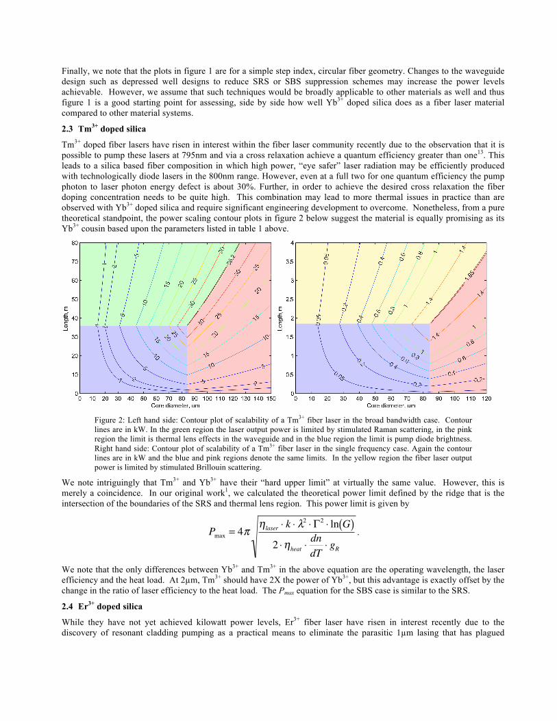
Tm3+ doped fiber lasers have risen in interest within the fiber laser community recently due to the observation that it is possible to pump these lasers at 795nm and via a cross relaxation achieve a quantum efficiency greater than one13. This leads to a silica based fiber composition in which high power, “eye safer” laser radiation may be efficiently produced with technologically diode lasers in the 800nm range. However, even at a full two for one quantum efficiency the pump photon to laser photon energy defect is about 30%. Further, in order to achieve the desired cross relaxation the fiber doping concentration needs to be quite high. This combination may lead to more thermal issues in practice than are observed with Yb3+ doped silica and require significant engineering development to overcome. Nonetheless, from a pure theoretical standpoint, the power scaling contour plots in figure 2 below suggest the material is equally promising as its Yb3+ cousin based upon the parameters listed in table 1 above.
Figure 2: Left hand side: Contour plot of scalability of a Tm3+ fiber laser in the broad bandwidth case. Contour lines are in kW. In the green region the laser output power is limited by stimulated Raman scattering, in the pink region the limit is thermal lens effects in the waveguide and in the blue region the limit is pump diode brightness. Right hand side: Contour plot of scalability of a Tm3+ fiber laser in the single frequency case. Again the contour lines are in kW and the blue and pink regions denote the same limits. In the yellow region the fiber laser output power is limited by stimulated Brillouin scattering.
We note intriguingly that Tm3+ and Yb3+ have their “hard upper limit” at virtually the same value. However, this is merely a coincidence. In our original work1, we calculated the theoretical power limit defined by the ridge that is the intersection of the boundaries of the SRS and thermal lens region. This power limit is given by
�
Pmax = 4πηlaser ⋅ k ⋅ λ
2 ⋅ Γ2 ⋅ ln G( )2 ⋅ηheat ⋅
dndT
⋅ gR.
We note that the only differences between Yb3+ and Tm3+ in the above equation are the operating wavelength, the laser efficiency and the heat load. At 2µm, Tm3+ should have 2X the power of Yb3+, but this advantage is exactly offset by the change in the ratio of laser efficiency to the heat load. The Pmax equation for the SBS case is similar to the SRS.
2.4 Er3+ doped silica
While they have not yet achieved kilowatt power levels, Er3+ fiber laser have risen in interest recently due to the discovery of resonant cladding pumping as a practical means to eliminate the parasitic 1µm lasing that has plagued

Er3+/Yb3+ lasers34. Resonant cladding pumping at wavelengths longer than 1480nm also has the highly beneficial effect of reducing the quantum defect of the Er3+ laser system quite significantly. Thus, as can be seen from figure 3 below, Er3+ fiber lasers have the theoretical capability to scale to power levels about 1.5X higher than Yb3+ doped silica fiber lasers. This is consistent with the Pmax equation from the section above on Tm3+.
Figure 3: Left hand side: Contour plot of scalability of an Er3+ fiber laser in the broad bandwidth case. Contour lines are in kW. In the green region the laser output power is limited by stimulated Raman scattering, in the pink region the limit is thermal lens effects in the waveguide and in the blue region the limit is pump diode brightness. Right hand side: Contour plot of scalability of a Er3+ fiber laser in the single frequency case. Again the contour lines are in kW and the blue and pink regions denote the same limits. In the yellow region the fiber laser output power is limited by stimulated Brillouin scattering. The purple region at the very bottom of the plot suggests the power is limited by thermal rupture. However, the real issue is that the dopant is so low the required absorption cannot be achieved in these lengths even with direct core pumping.
We note that a small region of the SBS plot for Erbium shows a thermal rupture effect. This is not real. For very short lengths of Erbium (<1m) 20dB of pump absorption cannot be achieved even with direct core pumping as the assumed dopant concentration is <20dB/m. In our original work we showed that requiring 20dB of absorption of the pump from the cladding creates a relationship between the cladding diameter, the core diameter, the core dopant concentration and the fiber length. We employ this relationship to eliminate the cladding diameter from our analysis. However, that relationship in the case of the small core absorptions or very short lengths leads to calculations of cladding diameters smaller than the core diameter. This is not physical. The rupture equation gives a negative power limit in this case, making it the limiting power. It is actually an indication that we cannot make an efficient laser at lengths this short and thus this region should be ignored in the plot.
From figure 3, Er3+ appears quite promising as a fiber laser material with a 50% higher maximum power limit than the Tm3+ and Yb3+ cases. However, the current limited diode laser brightness and core doping limitations prevent the realization of high power devices due to the requirement of core sizes >>50µm. Significant material advances allowing doping concentrations 10X higher than presently available with good efficiency and higher brightness diode lasers in the 1450-1550 nm range would be enabling for this materials composition.
2.5 Yb3+ doped phosphate
Phosphate is an intriguing alternative to silica as a fiber laser material. Rare earth doped phosphates have been well studied as laser materials and are employed in the world’s highest energy laser systems such as NIF, Omega and LMJ. Rare earths are much more easily dissolved in phosphate glasses than in silica glasses, leading to much stronger absorptions and the potential for shorter fiber lasers. This could be quite promising from a pulsed laser standpoint. However, currently there is only one source of commercial fiber lasers based upon phosphate glass fibers and based upon recent literature reports, these fibers are have high background losses severely limiting the fiber lengths8. We were unable to firmly establish the Raman gain coefficient from the literature. Thus it is hard to pin down a firm set of values for the scalability of a broadband phosphate fiber laser. We show two plots for the case of the highest possible Raman gain coefficient (established by bounding via reports of pulsed amplifier results) and the lowest estimated limit.

Figure 4: Left hand side: Contour plot of scalability of an Yb3+ phosphate fiber laser in the broad bandwidth case with gR=20X10-13m/W. Contour lines are in kW. In the green region the laser output power is limited by stimulated Raman scattering, in the pink region the limit is thermal lens effects in the waveguide, the small blue region the limit is pump diode brightness, the gray region is limited by damage and the orange region is limited by melting of the core. Right hand side: Contour plot of scalability of an Yb3+ phosphate fiber laser in the broad bandwidth case with gR=0.5X10⁻¹³m/W. Again the contour lines are in kW and the colors denote the same limits.
We see that even in the case of a Raman gain coefficient ½ of the silica Raman gain, the upper limit on power is only ½ the silica case. This is due to phosphate’s poor performance as a thermal conductor and relatively low reported CW damage threshold. The SBS limited case is similar in that the maximum power is about ½ that of Yb3+ doped silica. The one thing we do note about this material that is promising is that its dn/dT is negative. Thus one might conceive of a case where one started with a waveguide that was slightly multimode and as the material becomes hot, its NA drops improving the laser beam quality. In this case, the material could be more promising. For this to be the case, the Raman gain coefficient would need to be known better than it is now (and come in closer to the right hand picture than the left), the material would need to be improved from a background loss perspective (see next section) and the damage threshold would need to be better than what is currently reported in the literature. This latter event would be possible only if the current CW damage threshold could be improved with better material processing.
2.6 Yb3+ doped single crystal or ceramic YAG
Given that poor thermal conductivity and low damage threshold appears to be the primary weakness of the phosphate materials, it is appropriate that the last material in our analysis is YAG with a thermal conductivity 10X higher than silica and a similar expected damage threshold. In figure 5 below, we plot the power scaling limits of Yb3+ doped YAG.
Figure 5: Left hand side: Contour plot of scalability of an Yb3+ YAG fiber laser in the broad bandwidth case. Contour lines are in kW. In the green region the laser output power is limited by stimulated Raman scattering, in the pink region the limit is thermal lens effects in the waveguide, the blue region the limit is pump diode

brightness, the gray region is limited by damage. Right hand side: Contour plot of scalability of an Yb3+ phosphate fiber laser in the broad bandwidth case with the bandwidth broadened to 10X the SRS bandwidth limit. Again the contour lines are in kW and the colors denote the same limits.
We note that while the thermal conductivity of YAG is 10X higher than silica, so is the Raman. Thus the end result of the intersection of the SRS and thermal lens regions again yields a number near 33kW (the poorer efficiency of YAG yields slightly less power). However, the Raman gain in YAG is much higher than silica in part because the linewidth of the Raman gain is much narrower (270GHz or ~0.9nm) thus it is conceivable that this limit could be overcome by line broadening the laser to 10nm. In this case the right hand contour plot dominates and up to 114kW of laser power would possible providing the core size and laser lengths could be achieved, both of which are unlikely. As noted above the SBS limit is poorly known. Figure 6 below is a contour plot for the highest value of the SBS coefficient gB=5X10-12 m/W. In the best case scenario, the lowest value is irrelevant as the power becomes limited by the bandwidth broadened SRS case in the right hand side of figure 5 above.
Figure 6: Contour plot of scalability of an Yb3+ YAG fiber laser in the single frequency case. Contour lines are in kW. In the yellow region the laser output power is limited by stimulated Brillouin scattering, in the pink region the limit is thermal lens effects in the waveguide, the blue region the limit is pump diode brightness and the gray region is damage limited.
The maximum laser power in this case is 16.9 kW, which is a clear win over the Yb3+ doped silica fiber case. Given the short lengths involved in figure 6 above, it is not completely improbable that a 1m YAG rod with the correct core diameter could be fabricated and achieve a favorable output power compared to single frequency Yb3+ doped silica.
3. IMPACT OF BACKGROUND LOSS ON POWER SCALING Silica optical fibers have benefited greatly from decades of intensive development funded by the telecommunications industry. Thus production of silica optical fibers with losses <1dB/km in the 1µm range and <0.2dB/km in the 1.55µm range are common33. Further, the addition of a rare earth dopant and associated co-dopants such as Aluminum typically do not raise the background loss of the fibers above 10dB/km (a really bad loss by silica fiber standards). However, reports from other fiber lasers such as phosphate8 and YAG9, 10 suggest these less developed material systems show waveguide losses from 3dB/m to several dB/cm! It may be possible with sufficient materials development to overcome these losses. In the meantime, however, losses of this magnitude will have a significant impact on the laser efficiency and require strict limits on the fiber laser length. We estimate the maximum allowable length for a given loss and allowed efficiency reduction in section 3.1 below. We then return to the plots for Yb3+ doped phosphate (section 3.2) and YAG (section 3.3) and plot line outs of the power attainable at the maximum fiber length as a function of core diameter. This permits us to assess the maximum power achievable today from these material systems.
3.1 Maximum allowed laser length as a function of laser efficiency
Consider a fiber laser amplifier. The fiber has an intrinsic background loss per unit length, G- and when employed as an amplifier a gain per unit length G+. The net gain of the amplifier per unit length is Gnet=G+-G- and the power in the fiber laser amplifier as a function of position z evolves exponentially and is given by

�
P z( ) = Pin ⋅ eGnet ⋅z (1)
where Pin is the input power to the amplifier. The output power Pout at the end of the amplifier of length L is
�
Pout = Pin ⋅ eGnet ⋅L . (2)
At any point in the amplifier the power per unit length that lost by scattering or absorption, Plost(z) can be calculated from
�
dPlost z( )dz
= G− ⋅ P z( ) (3)
where P(z) is given by Eq. 1 above. Equation 3 can be integrated over the amplifier length to find the total lost power in the amplifier yielding
�
Plost = G−
Gnet
⋅ Pin ⋅ eGnet ⋅L −1( ) (4)
The fraction of the laser amplifier power that is lost is given by the ratio of the lost power to the total power that would have been generated by the amplifier.
�
ηlost = PlostPout − Pin + Plost
= G− /Gnet
1+ G− /Gnet
= G−
G+ (5)
where ηlost directly subtracts from the overall efficiency. Recall in our original work, we argued that the relevant gain for a high power fiber amplifier, G, is 10dB as the last 10dB of amplifier gain is where most of the power is extracted and where high efficiency is particularly important. The net gain per unit length Gnet is then
�
Gnet = GL
(6)
and G+=Gnet+G-. Substituting this and Eq. 6 back into equation 5, we can solve for the maximum fiber length allowed for a given background loss and allowed efficiency.
�
Lmax = ηloss
G− ⋅ 1−ηloss( )⋅G (7)
In figure 7, below we plot Lmax vs. background loss G- for G=10dB and ηloss from 10-50% in 10% increments.
Figure 7: Maximum amplifier length for a 10dB gain amplifier as a function of fiber background loss for various allowed efficiency reductions.

We see that for silica fiber background losses of 10dB/km or 0.01dB/m, a 100m long amplifier would result in only a 10% reduction in system efficiency. However, for a 3dB/m phosphate fiber8, a 10% efficiency reduction occurs at 0.5m and a 1m long fiber will suffer ~25% reduction in efficiency. For materials that have losses higher than phosphate, the maximum realistic fiber length quickly drops into the few cm realm at which point we do not really see the advantage of a fiber geometry.
3.2 Yb3+ doped phosphate
Existing literature reports suggest that the loss in current state-of-the-art Yb3+ doped phosphate fibers is around 3dB/m with approximately 2dB/m of absorption losses and 1dB/m of scattering losses. The 1dB/m scattering loss is concerning from an efficiency standpoint, but otherwise unremarkable. The 2dB/m of absorption loss may lead to a significantly higher than expected thermal load. To this end, we would like the fiber to be as short as possible to minimize the amount of power converted to heat. Based upon figure 7, we suggest looking at a 0.5m (10% efficiency reduction) and 1.0m case (25% efficiency reduction). We will look only at the case of gR =0.5X10⁻¹³m/W, the higher Raman gain case will only be worse. In figure 8 below, we generate line-outs from the contour plots of figure 4 at the 0.5m and 1.0m cases.
Figure 8: Line outs from figure 4 at 0.5m where the red line is the line-out from the SBS limited contour plot and the blue line is the line-out from the SRS limited contour plot. The green line is the 1m case in which we look only at the SRS limited contour plot.
The plot above shows three distinct regions. Below 10µm core diameter we see the pump coupling region, where power is growing with core diameter as we can absorb more pump light from diodes of finite brightness. Between 10µm and 40µm, the output power is limited by thermal melting of the core. At core diameters above 40µm the power decreases with increasing core diameter due to thermal lens effects. Based upon the blue and green lines, the power is scaling roughly linearly with fiber length. While the contour plots suggest a low loss phosphate fiber may be capable of as much as 19kW, it is clear from figure y above that present phosphate fibers will struggle to reach even 1kW with their high background losses.
3.3 Yb3+ doped single crystal or ceramic YAG
Reports in the literature of loss in attempts to make ceramic YAG fibers are ludicrously high. For these fibers to be practical, they would need to be much, much lower. However, there is an additional constraint on the fiber length in that YAG is not a glass and likely cannot be bent. To this end, we restrict the fiber length to 1m and look at line outs assuming the loss of a YAG fiber can be lowered to at least 1-2dB/m. Examination of the contour plots in figures 5 and 6 suggests that at 1m the relevant limits are damage and thermal lens effects in all but the case of the highest SBS gain. In that case, the relevant limit is SBS and thermal lens effects. Figure 9 below is a line out for the highest SBS limited gain at 1m and for the damage-thermal lens limited cases from the other contour plots.

Figure 9: Line-outs at 1m length. Blue line is damage limited at core diameters below 5µm and thermal lens limited above 50µm. Red line is SBS limited in the case of the highest estimated YAG SBS gain below 65µm and thermal lens limited above this point.
While this line-out does not suggest higher broadband power than is available from a silica optical fiber, it certainly suggests that a low loss ceramic YAG fiber might perform considerably better in the single frequency limited case that Yb3+ doped silica. This is true even if we assume the worst case expected SBS gain for YAG.
4. SUMMARY We have applied our previous analysis for Yb3+ doped silica fiber to other materials, particularly phosphate doped glasses, ceramic YAG fibers and Tm3+ and Er3+ doped fibers. All of these materials would require significant materials development to compete with Yb3+ doped silica in output power. Er3+ is perhaps the closest in terms of materials development, but has only 50% more potential power. However, Er3+ is at an eye safe wavelength, which may make it worth pursuing for that reason alone. Phosphate may be a promising material if the damage threshold of a pure material is higher than the current samples and the fibers could be fabricated with low background loss. YAG fibers could be very promising for single frequency based fiber lasers as it appears 18kW single frequency devices may be possible.
REFERENCES
[1] Dawson, J.W., Messerly, M.J., Beach, R.J., Shverdin, M.Y., Stappaerts, E.A., Sridharan, A.K., Pax, P.H., Heebner J.E., Siders C.W. and Barty, C.P.J., “Analysis of the scalability of diffraction limited fiber lasers and amplifiers to high average power,” Optics Express, 16, 13240-13266 (2008)
[2] Carter, A. and Samson. B., “New technology advances applications for high-power fiber lasers,” Military Aerospace Electronics, 16, 16-21 (2005)
[3] Tunnerman, A., Schreiber, T., Roser, F., Liem, A., Hofer, S., Zellmer, H., Nolte, S. and Limpert, J., “The renaissance and bright future of fiber lasers,” Journal of Physics B, 38, 681-693 (2003)
[4] Payne, D., Jeong, Y., Nilsson, J., Sahu, J.K., Soh, D.B.S., Alegria, C., Dupriez, P., Codemard, C.A., Philippov, V.N. and Hernandez, V., “Kilowatt-class single-frequency fiber sources,” Proceedings of the SPIE, 5709, 133-141 (2005)
[5] Yusim, A., “Recent progress in scaling of high power fiber lasers at IPG Photonics,” presented at Solid State and Diode Laser Technology Review, Newton, MA, June 29-July 2, 2009
[6] Ehernreich, T., Leveille, R., Majid, I., Kanishka, T., Rines, G and Moulton, P., “1-kW, All-Glass Tm: Fiber Laser,” Post-Deadline Session, Fiber Lasers VII: Technology, Systems and Applications, Photonics West Conference 7580 (2010)
[7] Dubinskii, M., Zhang, J., Ter-Mirirtychev, V., “Highly scalable, resonantly cladding-pumped, Er-doped fiber laser with record efficiency,” Optics Letters, 34, 1507-1509 (2009)
[8] Lee, Y.W., Digonnet, M.J.F., Sinha, S., Urbanek, K.E., Byer, R.L. and Jiang, S., “High power Yb3+ doped phosphate fiber amplifier,” IEEE Journal of Selected Topics in Quantum Electronics, 15, 93-102 (2009)

[9] Ballato, J., Hawkins, T., Foy, P., Kokuoz, B., Stolen, R., McMillen, C., Daw, M., Su, Z., Tritt, T.M., Dubinskii, M., Zhang, J., Sanamyan, T. and Matthewson, M.J., “On the fabrication of all-glass optical fibers from crystals,” Journal of Applied Physics, 105, 053110 (2009)
[10] Lai, C.C., Huang, K.Y., Tsai, H.J., Hsu, K.Y., Liu, S.K., Cheng, C.T., Ji, K.D., Ke, C.P., Lin, S.R. and Huang, S.L., “Yb3+:YAG silica fiber laser,” Optics Letters, 34, 2357-2359 (2009)
[11] Continuous wave damage fluence for fused silica is a lower bound based upon physical demonstrations and are the author’s calculations of IPG achieved flueneces at 1-10kW based upon statements made by IPG representatives in conference presentations such as reference 5 above where core diameter and power levels have been discussed.
[12] Based upon Laserline Inc. (www.laserline-inc.com/diode_laser_material_processing.html) LDM and LDF 9000W fiber coupled laser diode product (1000µm fiber, 0.2NA).
[13] Moulton, P.F., Rines, G.A., Slobodtchikov, E.V., Wall, K.F., Frith, G., Samson, B. and Carter, A.L.G., “Tm-doped fiber lasers: fundamentals and power scaling,” IEEE Journal of Selected Topics in Quantum Electronics, 15, 85-92 (2009)
[14] Typical Nufern specialty fiber data sheet. (www.nufern.com) [15] Current pump brightness for 790nm diode laser is not as high as the 9xx nm diodes. However, it is technically
plausible that these devices could easily achieve similar brightness with a small engineering effort. [16] 14xx nm/15xx nm pump diodes are much less common than 7xx – 9xx nm diodes. Brightness is correspondingly
lower based upon nLight datasheet (www.nlight.net/fiber_coupled/details/56~Pearl-Medical-Series-Alpha-Release). Greater engineering effort and investment is probably needed in diodes at these wavelengths to achieve brightness comparable to the 9xx nm state-of-the-art.
[17] Erbium only fibers can be purchased with up to 120dB/m (www.nlight.net). However, in the author’s experience, only the lower doped fibers are capable of providing high (>80%) power conversion efficiencies.
[18] Note: A complete self-consistent set of materials parameters could not be found for Yb3+ doped phosphate, a combination of LG 750 and literature reports was used in this table. However, the compositions employed in fiber manufacture vary widely and are not always fully reported in a manner that makes determining specific physical properties possible.
[19] Krupke, W.F., Shinn, M.D., Marion, J.E., Caird, J.A., Stokowski, S.E., “Spectroscopic, optical, and thermo-mechanical properties of neodymium- and chromium-doped gadolinium scandium gallium garnet,” Journal of the Optical Society of America B, 3, 102-114 (1986)
[20] Values taken from Schott data sheet for LG750 (www.schott.com/advanced_optics/english/download/lg_750_g.pdf) NA was determined by using the LG750 glass index and comparing it to the index of the standard pump cladding polymer for silica fibers.
[21] Leigh, M., Shi, W., Zong, J., Yao, Z., Jiang, S. and Peyghambarian, “High peak power single frequency pulses using a short polarization-maintaining phosphate glass fiber with a large core,” Applied Physics Letters, 92, 181108 (2008). Raman gain coefficient was estimated as an upper bound based upon 51kW peak power result from this paper.
[22] Beshar, A.H. and Aly, M.H., “Raman gain and Raman gain coefficient for SiO2, GeO2, B2O3 and P2O5 glasses,” 24th National Radio Science Conference (NRSC 2007), March 13-15, 2007. Suggests Raman gain coefficient for phosphate may be as low as ½ that of silica.
[23] Lee, Y.W., Digonnet, M.J.F., Sinha, S., Urbanek, K.E., Byer, R.L. and Jiang, S., “High Power Yb3+ doped phosphate fiber amplifier,” IEEE Journal of Quantum Electronics, 15, pp. 93-102 (2009)
[24] Gaume, R., Viana, B., Vivien, D., Roger, J.P. and Fournier, D., “A simple model for the prediction of thermal conductivity in pure and doped insulating material,” Applied Physics Letters, 83, 1355-1357 (2003)
[25] Jaroslav, J.L. and Viechnicki, D.J., “Study of the melting behavior of YAG single crystal by optical differential thermal analysis,” Report issued by Army Materials and Mechanics Research Center, Watertown, MA, Nov. 1979
[26] Aggarwal, R.L., Ripin, D.J., Ochoa, J.R. and Fan, T.Y., “Measurement of thermo-optic properties of Y3Al5O12, Lu3Al5O12, YAlO3, LiYF4, LiLuF4, BaYF8, KGd(WO4)2, and KY(WO4)2 laser crystals in the 80-300K temperature range,” Journal of Applied Physics, 98, 103514 (2005)
[27] Kaminskii, A.A., Eichler, H.J., Ueda, K., Bagaev, S.N., Gad, G.M.A., Lu, J., Murai, T., Yagi, H. and Yanagitani, T., “Observation of stimulated Raman scattering in Y2Al5O12 single crystals and nanocrystalline ceramics and in these materials activated with laser ions Nd3+ and Yb3+,” JETP Letters, 72, 499-502 (2000)
[28] Author estimate of potential range of Brillouin gain coefficient scaled from the known value for silica. Scaling was based upon reported values of material parameters for YAG and silica and equation for gain coefficient from, Faris,

G.W., Jusinski, L.E. and Hickman, A.P., “High-resolution stimulated Brillioun gain spectroscopy in glasses and crystals,” Journal of the Optical Society of America B, 10, 587-599 (1993)
[29] CW Damage threshold not known, but literature suggests pulsed damage threshold is about ½ that of silica. Thus CW damage threshold is estimated to ½ that of silica. Pulsed damage threshold used were taken from two papers by the same author. Do, B.T. and Smith, A.V., “Bulk optical damage thresholds for doped and undoped, crystalline and ceramic yttrium aluminum garnet,” Applied Optics, 48, 3509-3514 (2009) and Smith, A.V. and Do, B.T., “Bulk and surface laser damage of silica by picosecond and nanosecond pulses at 1064nm,” Applied Optics, 47, 4812-4832 (2008)
[30] Zhou, Y., Thai, Q., Chen, Y.C. and Zhou S., “Monolithic Q-switched Cr, Yb:YAG laser,” Optics Communications, 219, 365-367 (2003)
[31] Giesen, A., “High-power thin-disk lasers,” Presented at Advanced Solid State Photonics, paper MA1 (2007). [32] Based upon comparison of refractive index of YAG with polymer coating index needed to achieve NA of 0.45 for
silica optical fibers. Refractive index for YAG may be found: Dodge, M.J., in Handbook of Laser Science and Technology, edited by M.J. Weber, (Chemical Rubber Co., Boca Raton, 1986), Vol. 3, Pt. 1, Sec. 1.1
[33] See for example a typical commercial telecom optical fiber data sheet (http://www.ofsoptics.com/index.php). [34] Jeong, Y., Yoo, S., Codemard, C.A., Nilsson, J., Sahu, J.K., Payne, D.N., Horley, R., Turner, P.W., Hickey, L.,
Harker, A., Lovelady, M. and Piper, A., “Erbium:Ytterbium codoped large-core fiber laser with 297-W continuous-wave output power,” IEEE Journal of Selected Topics in Quantum Electronics, 13, 573-579 (2007)