power one rectifier manual
DESCRIPTION
Power One Rectifier ManualTRANSCRIPT

Power Supply SystemGDN.C.48.10 POS
Instruction Manual
Document Number: BCG.00003 Rev: AA

Copyright © 1999-2009 Power-One, Inc.
All Rights Reserved
Restricted Rights Legend:
Use, duplication, or disclosure by the Government is subject to restrictions as set forth in subparagraph © (1)(ii) of the Rights in Technical Data and Computer Software clause at DFARS 252.227-7013 or subparagraphs © (1) and (2) of Commercial Computer Software - Restricted Rights at 48 CFR 52.227-19, as applicable.
For Contact Information, please go to http://www.power-one.com/contact/
Refer to the Power-One License Agreement in this package before installing or using this product.
Unless specifically noted, all addresses, data characters and persons referenced herein, and all examples involving names of companies and products, are fictitious examples and are designed solely to illustrate the use of Power-One products.
Product names, logos, brands, and other trademarks featured or referred to within this product manual are the property of their respective trademark holders. These trademark holders are not affiliated with Power-One, Inc. or our products. They do not sponsor or endorse our products.
LIMITATIONS AND AUTHORIZATIONS FOR USE AND PERMITTED APPLICATIONS
Power-One's products are not designed, intended for use in, or authorized for use as critical components in, human life support systems/equipment, equipment used in hazardous environments, or equipment used in nuclear control equipment or systems. Any such use requires the prior express written consent of an authorized executive officer of Power-One, Inc., which consent may be withheld by Power-One, Inc. in its sole discretion. Users assume all risk and liability for, and agree to indemnify and defend Power-One from and against any claims for personal injury (including death) or property damage resulting from any such use or application which is made in the absence of such prior express written consent.
If you find errors or problems with this documentation, please notify Power-One. Power-One does not guarantee that this document is error-free. The information in this document is subject to change without notice.
BCG.00003
June 2009
Contents iii
Contents
Chapter 1 About This Manual . . . . . . . . . . . . . . . . . . . . . . . . . . . . . .1-11.1 Objectives . . . . . . . . . . . . . . . . . . . . . . . . . . . . . . . . . . . . . . . . . . . . . . . . . . . . . . 1-11.2 Audience . . . . . . . . . . . . . . . . . . . . . . . . . . . . . . . . . . . . . . . . . . . . . . . . . . . . . . . 1-11.3 Document Key. . . . . . . . . . . . . . . . . . . . . . . . . . . . . . . . . . . . . . . . . . . . . . . . . . . 1-21.4 Feedback & Support . . . . . . . . . . . . . . . . . . . . . . . . . . . . . . . . . . . . . . . . . . . . . . 1-31.5 Layout, Numbering and Printing . . . . . . . . . . . . . . . . . . . . . . . . . . . . . . . . . . . . . 1-31.6 Disclaimer . . . . . . . . . . . . . . . . . . . . . . . . . . . . . . . . . . . . . . . . . . . . . . . . . . . . . . 1-3
Chapter 2 System Description . . . . . . . . . . . . . . . . . . . . . . . . . . . . .2-12.1 General . . . . . . . . . . . . . . . . . . . . . . . . . . . . . . . . . . . . . . . . . . . . . . . . . . . . . . . . 2-12.2 Technical Data. . . . . . . . . . . . . . . . . . . . . . . . . . . . . . . . . . . . . . . . . . . . . . . . . . . 2-32.3 Operation . . . . . . . . . . . . . . . . . . . . . . . . . . . . . . . . . . . . . . . . . . . . . . . . . . . . . . 2-42.4 System Overview . . . . . . . . . . . . . . . . . . . . . . . . . . . . . . . . . . . . . . . . . . . . . . . . 2-5
2.4.1 System Controller. . . . . . . . . . . . . . . . . . . . . . . . . . . . . . . . . . . . . . . . . . . . 2-52.4.2 Rectifier Module . . . . . . . . . . . . . . . . . . . . . . . . . . . . . . . . . . . . . . . . . . . . . 2-52.4.3 Rectifier Subrack . . . . . . . . . . . . . . . . . . . . . . . . . . . . . . . . . . . . . . . . . . . . 2-82.4.4 PBDU 23” - Distribution module . . . . . . . . . . . . . . . . . . . . . . . . . . . . . . . . 2-82.4.5 AC Distribution . . . . . . . . . . . . . . . . . . . . . . . . . . . . . . . . . . . . . . . . . . . . . . 2-9
2.4.5.1 Low Voltage Disconnection (LVD) . . . . . . . . . . . . . . . . . . . . . . . . . . . 2-92.4.5.2 Partial Load Disconnection (PLD) (Option) . . . . . . . . . . . . . . . . . . . . 2-9
Chapter 3 System Safety . . . . . . . . . . . . . . . . . . . . . . . . . . . . . . . . .3-13.1 Safety Warnings and Guidelines. . . . . . . . . . . . . . . . . . . . . . . . . . . . . . . . . . . . . 3-1
3.1.1 System Markings . . . . . . . . . . . . . . . . . . . . . . . . . . . . . . . . . . . . . . . . . . . . 3-13.1.2 Safety Recommendations . . . . . . . . . . . . . . . . . . . . . . . . . . . . . . . . . . . . . 3-23.1.3 Installation Warning . . . . . . . . . . . . . . . . . . . . . . . . . . . . . . . . . . . . . . . . . . 3-23.1.4 Restricted Access Area Warnings . . . . . . . . . . . . . . . . . . . . . . . . . . . . . . . 3-23.1.5 Operating Temperature Warnings . . . . . . . . . . . . . . . . . . . . . . . . . . . . . . . 3-33.1.6 Electrical Safety Warnings . . . . . . . . . . . . . . . . . . . . . . . . . . . . . . . . . . . . . 3-33.1.7 Grounding. . . . . . . . . . . . . . . . . . . . . . . . . . . . . . . . . . . . . . . . . . . . . . . . . . 3-43.1.8 Batteries . . . . . . . . . . . . . . . . . . . . . . . . . . . . . . . . . . . . . . . . . . . . . . . . . . . 3-4
3.1.8.1 Lead Acid Batteries . . . . . . . . . . . . . . . . . . . . . . . . . . . . . . . . . . . . . . 3-43.1.9 In Case of an Accident . . . . . . . . . . . . . . . . . . . . . . . . . . . . . . . . . . . . . . . . 3-5
3.2 Caution . . . . . . . . . . . . . . . . . . . . . . . . . . . . . . . . . . . . . . . . . . . . . . . . . . . . . . . . 3-53.2.1 Storage and Transportation . . . . . . . . . . . . . . . . . . . . . . . . . . . . . . . . . . . . 3-5

iv GDN.C.48.10 POS Power Supply System Instruction Manual
3.2.2 Disposal. . . . . . . . . . . . . . . . . . . . . . . . . . . . . . . . . . . . . . . . . . . . . . . . . . . 3-53.2.3 Handling Electrostatic Sensitive Devices . . . . . . . . . . . . . . . . . . . . . . . . . 3-63.2.4 Traceability . . . . . . . . . . . . . . . . . . . . . . . . . . . . . . . . . . . . . . . . . . . . . . . . 3-63.2.5 Breakers . . . . . . . . . . . . . . . . . . . . . . . . . . . . . . . . . . . . . . . . . . . . . . . . . . 3-63.2.6 Hot Surfaces . . . . . . . . . . . . . . . . . . . . . . . . . . . . . . . . . . . . . . . . . . . . . . . 3-6
Chapter 4 Installation Guide . . . . . . . . . . . . . . . . . . . . . . . . . . . . . . .4-14.1 Preface. . . . . . . . . . . . . . . . . . . . . . . . . . . . . . . . . . . . . . . . . . . . . . . . . . . . . . . . 4-14.2 Unpacking . . . . . . . . . . . . . . . . . . . . . . . . . . . . . . . . . . . . . . . . . . . . . . . . . . . . . 4-14.3 Tools required. . . . . . . . . . . . . . . . . . . . . . . . . . . . . . . . . . . . . . . . . . . . . . . . . . . 4-24.4 Installation Procedure. . . . . . . . . . . . . . . . . . . . . . . . . . . . . . . . . . . . . . . . . . . . . 4-3
4.4.1 Cabinet Mounting . . . . . . . . . . . . . . . . . . . . . . . . . . . . . . . . . . . . . . . . . . . 4-34.4.2 Grounding . . . . . . . . . . . . . . . . . . . . . . . . . . . . . . . . . . . . . . . . . . . . . . . . . 4-44.4.3 Cable sizes . . . . . . . . . . . . . . . . . . . . . . . . . . . . . . . . . . . . . . . . . . . . . . . . 4-54.4.4 Connection of Mains . . . . . . . . . . . . . . . . . . . . . . . . . . . . . . . . . . . . . . . . . 4-64.4.5 Alarm Connection . . . . . . . . . . . . . . . . . . . . . . . . . . . . . . . . . . . . . . . . . . . 4-84.4.6 Symmetry and Temperature Sensor . . . . . . . . . . . . . . . . . . . . . . . . . . . . . 4-9
4.5 Installation of Rectifiers . . . . . . . . . . . . . . . . . . . . . . . . . . . . . . . . . . . . . . . . . . 4-104.6 Battery Connection. . . . . . . . . . . . . . . . . . . . . . . . . . . . . . . . . . . . . . . . . . . . . . 4-124.7 DC Connection . . . . . . . . . . . . . . . . . . . . . . . . . . . . . . . . . . . . . . . . . . . . . . . . . 4-13
Chapter 5 Commissioning. . . . . . . . . . . . . . . . . . . . . . . . . . . . . . . . .5-15.1 Commissioning Overview. . . . . . . . . . . . . . . . . . . . . . . . . . . . . . . . . . . . . . . . . . 5-15.2 Tools and Test Equipment . . . . . . . . . . . . . . . . . . . . . . . . . . . . . . . . . . . . . . . . . 5-2
5.2.1 Tools List . . . . . . . . . . . . . . . . . . . . . . . . . . . . . . . . . . . . . . . . . . . . . . . . . . 5-25.2.2 Test Equipment . . . . . . . . . . . . . . . . . . . . . . . . . . . . . . . . . . . . . . . . . . . . . 5-2
5.3 Preparation. . . . . . . . . . . . . . . . . . . . . . . . . . . . . . . . . . . . . . . . . . . . . . . . . . . . . 5-25.4 Commissioning Procedure . . . . . . . . . . . . . . . . . . . . . . . . . . . . . . . . . . . . . . . . . 5-25.5 Test of output voltage . . . . . . . . . . . . . . . . . . . . . . . . . . . . . . . . . . . . . . . . . . . . . 5-4
5.5.1 Float charge (U1). . . . . . . . . . . . . . . . . . . . . . . . . . . . . . . . . . . . . . . . . . . . 5-45.5.2 Adjustment of Float Charge, U1 . . . . . . . . . . . . . . . . . . . . . . . . . . . . . . . . 5-45.5.3 Boost Charging (U2) (if applicable) . . . . . . . . . . . . . . . . . . . . . . . . . . . . . . 5-4
5.6 Battery Supervision . . . . . . . . . . . . . . . . . . . . . . . . . . . . . . . . . . . . . . . . . . . . . . 5-55.7 Battery test . . . . . . . . . . . . . . . . . . . . . . . . . . . . . . . . . . . . . . . . . . . . . . . . . . . . . 5-55.8 Commissioning record . . . . . . . . . . . . . . . . . . . . . . . . . . . . . . . . . . . . . . . . . . . . 5-6
Chapter 6 System Controller PCC . . . . . . . . . . . . . . . . . . . . . . . . . .6-16.1 General - Product description PCC w/Display . . . . . . . . . . . . . . . . . . . . . . . . . . 6-16.2 Technical specification:. . . . . . . . . . . . . . . . . . . . . . . . . . . . . . . . . . . . . . . . . . . . 6-26.3 Operation - Introduction . . . . . . . . . . . . . . . . . . . . . . . . . . . . . . . . . . . . . . . . . . . 6-2
6.3.1 Starting the PCC. . . . . . . . . . . . . . . . . . . . . . . . . . . . . . . . . . . . . . . . . . . . 6-36.3.2 Adding modules. . . . . . . . . . . . . . . . . . . . . . . . . . . . . . . . . . . . . . . . . . . . . 6-46.3.3 Removing modules . . . . . . . . . . . . . . . . . . . . . . . . . . . . . . . . . . . . . . . . . . 6-46.3.4 PCC Control . . . . . . . . . . . . . . . . . . . . . . . . . . . . . . . . . . . . . . . . . . . . . . . 6-46.3.5 PCC Icons . . . . . . . . . . . . . . . . . . . . . . . . . . . . . . . . . . . . . . . . . . . . . . . . . 6-56.3.6 PCC Menus . . . . . . . . . . . . . . . . . . . . . . . . . . . . . . . . . . . . . . . . . . . . . . . . 6-6
6.3.6.1 Show voltage and currents . . . . . . . . . . . . . . . . . . . . . . . . . . . . . . . . 6-76.3.6.2 Show alarms . . . . . . . . . . . . . . . . . . . . . . . . . . . . . . . . . . . . . . . . . . . 6-76.3.6.3 Show messages . . . . . . . . . . . . . . . . . . . . . . . . . . . . . . . . . . . . . . . . 6-76.3.6.4 Show data. . . . . . . . . . . . . . . . . . . . . . . . . . . . . . . . . . . . . . . . . . . . . 6-76.3.6.5 Controller failure . . . . . . . . . . . . . . . . . . . . . . . . . . . . . . . . . . . . . . . . 6-86.3.6.6 Select / adjust U1 - U4 . . . . . . . . . . . . . . . . . . . . . . . . . . . . . . . . . . . 6-8
Contents v
6.3.6.7 Adjust limits . . . . . . . . . . . . . . . . . . . . . . . . . . . . . . . . . . . . . . . . . . . . 6-96.3.6.8 Miscellaneous . . . . . . . . . . . . . . . . . . . . . . . . . . . . . . . . . . . . . . . . . 6-11
6.3.7 Connecting to PC . . . . . . . . . . . . . . . . . . . . . . . . . . . . . . . . . . . . . . . . . . . 6-146.3.8 Connecting a Modem . . . . . . . . . . . . . . . . . . . . . . . . . . . . . . . . . . . . . . . . 6-166.3.9 Boost charging . . . . . . . . . . . . . . . . . . . . . . . . . . . . . . . . . . . . . . . . . . . . . 6-166.3.10 Battery test . . . . . . . . . . . . . . . . . . . . . . . . . . . . . . . . . . . . . . . . . . . . . . . 6-176.3.11 Temperature compensation . . . . . . . . . . . . . . . . . . . . . . . . . . . . . . . . . . 6-186.3.12 High load . . . . . . . . . . . . . . . . . . . . . . . . . . . . . . . . . . . . . . . . . . . . . . . . 6-18
Chapter 7 Product Description AC Distribution. . . . . . . . . . . . . . . . .7-17.1 Technical specifications. . . . . . . . . . . . . . . . . . . . . . . . . . . . . . . . . . . . . . . . . . . . 7-17.2 Cable cross section output connections . . . . . . . . . . . . . . . . . . . . . . . . . . . . . . . 7-27.3 Installation . . . . . . . . . . . . . . . . . . . . . . . . . . . . . . . . . . . . . . . . . . . . . . . . . . . . . . 7-27.4 Commissioning PBDU. . . . . . . . . . . . . . . . . . . . . . . . . . . . . . . . . . . . . . . . . . . . . 7-27.5 Maintenance . . . . . . . . . . . . . . . . . . . . . . . . . . . . . . . . . . . . . . . . . . . . . . . . . . . . 7-2
Chapter 8 Maintenance & Troubleshooting. . . . . . . . . . . . . . . . . . . .8-18.1 Installing new Rectifiers . . . . . . . . . . . . . . . . . . . . . . . . . . . . . . . . . . . . . . . . . . . 8-18.2 Troubleshooting . . . . . . . . . . . . . . . . . . . . . . . . . . . . . . . . . . . . . . . . . . . . . . . . . 8-18.3 Maintenance . . . . . . . . . . . . . . . . . . . . . . . . . . . . . . . . . . . . . . . . . . . . . . . . . . . . 8-48.4 Torque Table . . . . . . . . . . . . . . . . . . . . . . . . . . . . . . . . . . . . . . . . . . . . . . . . . . . . 8-5
Appendix A Drawings . . . . . . . . . . . . . . . . . . . . . . . . . . . . . . . . . . . A-1A.1 Cabinet Layout GDN.C.48.10 POS - BCE.00028 - Rev.: AA . . . . . . . . . . . . . . . A-2A.2 Installation Drawing GDN.C.48.10 POS - BCE.00029 - Rev.: AA . . . . . . . . . . . A-3A.3 Block Diagram GDN.C.48.10 POS -044014 - Rev.: AB . . . . . . . . . . . . . . . . . . . A-4A.4 Schematic Diagram 2xsubrack w/AC distr. - BCE.00030 - Rev.: AA . . . . . . . . . A-5A.5 Schematic Diagram PBDU GDN.C.48.M24 - 043961 - Rev.: AB . . . . . . . . . . . . A-6
Appendix B Configuration PCC (C-000548) . . . . . . . . . . . . . . . . . . B-1
Appendix C Distribution GDN.C.48.10 POS . . . . . . . . . . . . . . . . . . C-1
Appendix D AC Distribution . . . . . . . . . . . . . . . . . . . . . . . . . . . . . . D-1

vi GDN.C.48.10 POS Power Supply System Instruction Manual
About This Manual 1-1
Power-One Document Number: 039462.fm Rev. AF2
Chapter 1 About This Manual
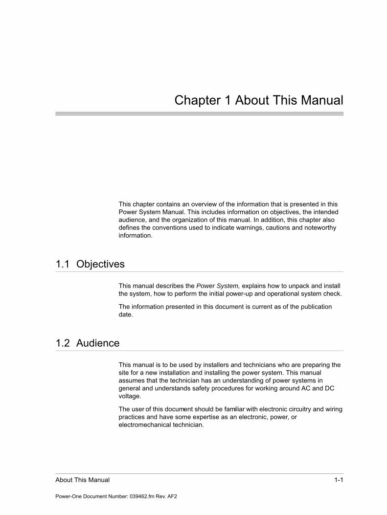
This chapter contains an overview of the information that is presented in this Power System Manual. This includes information on objectives, the intended audience, and the organization of this manual. In addition, this chapter also defines the conventions used to indicate warnings, cautions and noteworthy information.
1.1 Objectives
This manual describes the Power System, explains how to unpack and install the system, how to perform the initial power-up and operational system check.
The information presented in this document is current as of the publication date.
1.2 Audience
This manual is to be used by installers and technicians who are preparing the site for a new installation and installing the power system. This manual assumes that the technician has an understanding of power systems in general and understands safety procedures for working around AC and DC voltage.
The user of this document should be familiar with electronic circuitry and wiring practices and have some expertise as an electronic, power, or electromechanical technician.
1-2 Power Supply System Instruction Manual
Power-One Document Number: 039462.fm Rev. AF2
Document Key
1.3 Document Key
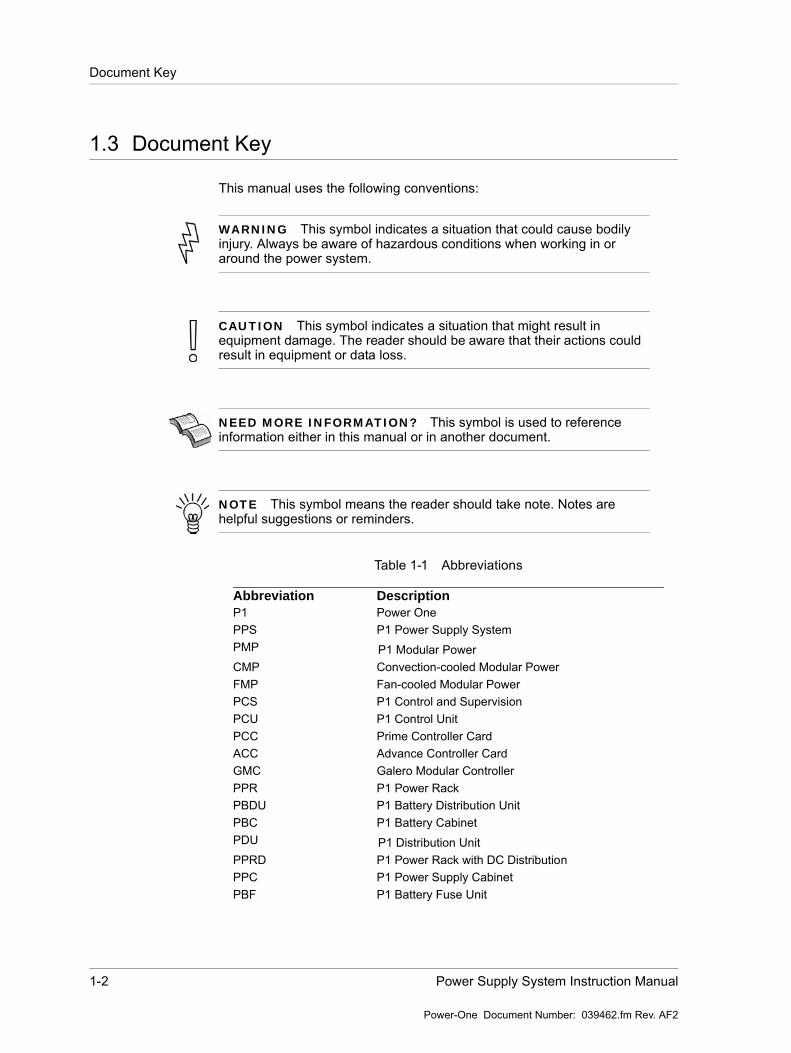
This manual uses the following conventions:
Table 1-1 Abbreviations
WARNING This symbol indicates a situation that could cause bodily injury. Always be aware of hazardous conditions when working in or around the power system.
CAUTION This symbol indicates a situation that might result in equipment damage. The reader should be aware that their actions could result in equipment or data loss.
NEED MORE INFORMATION? This symbol is used to reference information either in this manual or in another document.
NOTE This symbol means the reader should take note. Notes are helpful suggestions or reminders.
Abbreviation DescriptionP1 Power OnePPS P1 Power Supply SystemPMP P1 Modular PowerCMP Convection-cooled Modular PowerFMP Fan-cooled Modular PowerPCS P1 Control and SupervisionPCU P1 Control UnitPCC Prime Controller CardACC Advance Controller CardGMC Galero Modular ControllerPPR P1 Power RackPBDU P1 Battery Distribution UnitPBC P1 Battery CabinetPDU P1 Distribution UnitPPRD P1 Power Rack with DC DistributionPPC P1 Power Supply CabinetPBF P1 Battery Fuse Unit
About This Manual 1-3
Power-One Document Number: 039462.fm Rev. AF2
Feedback & Support
1.4 Feedback & Support
For technical support or feedback, please visit
http://www.power-one.com/contact/
Contact telephone numbers are:
1.5 Layout, Numbering and Printing
This manual is intended for two-sided black and white printing. Some pages are intentionally left blank.
The pages are numbered consecutively within each chapter, prefixed by the chapter number.
1.6 Disclaimer
Power-One is not responsible for system problems that are the result of installation or modification of the instructions provided in this manual.
PCB Printed Circuit BoardLVD Low voltage disconnectionPLD Partial load disconnectionMCB Miniature circuit breakerMCCB Moulded case circuit breakerXR Xscend RectifierDFC Direct Fan CoolingPODS P1 Outdoor SystemBTS Base Transceiver Station
Region Contact Number
Asia/Pacific + 65-6896-3363
Europe, Middle East, and Africa + 800-76937663
The Americas and Caribbean + 1-805-987-8742

1-4 Power Supply System Instruction Manual
Power-One Document Number: 039462.fm Rev. AF2
Disclaimer
System Description 2-1
Power-One. Document Number: 046078 Rev. AA
Chapter 2 System Description
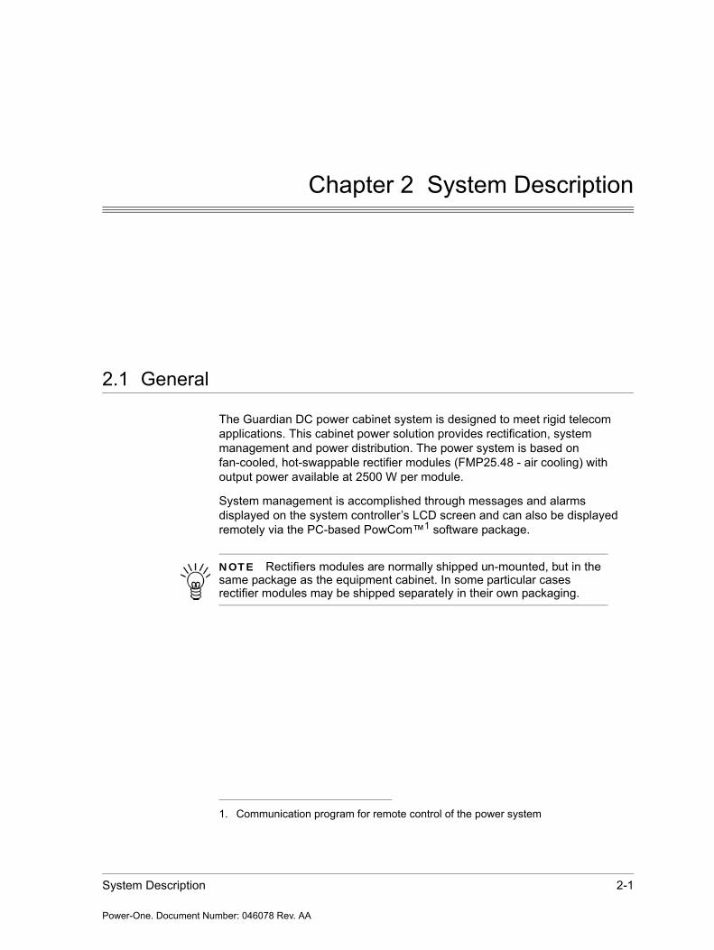
2.1 General
The Guardian DC power cabinet system is designed to meet rigid telecom applications. This cabinet power solution provides rectification, system management and power distribution. The power system is based on fan-cooled, hot-swappable rectifier modules (FMP25.48 - air cooling) with output power available at 2500 W per module.
System management is accomplished through messages and alarms displayed on the system controller’s LCD screen and can also be displayed remotely via the PC-based PowCom™1 software package.
1. Communication program for remote control of the power system
NOTE Rectifiers modules are normally shipped un-mounted, but in the same package as the equipment cabinet. In some particular cases rectifier modules may be shipped separately in their own packaging.
2-2 GDN.C.48.10 POS Power Supply System Instruction Manual
Power-One. Document Number: 046078 Rev. AA
General
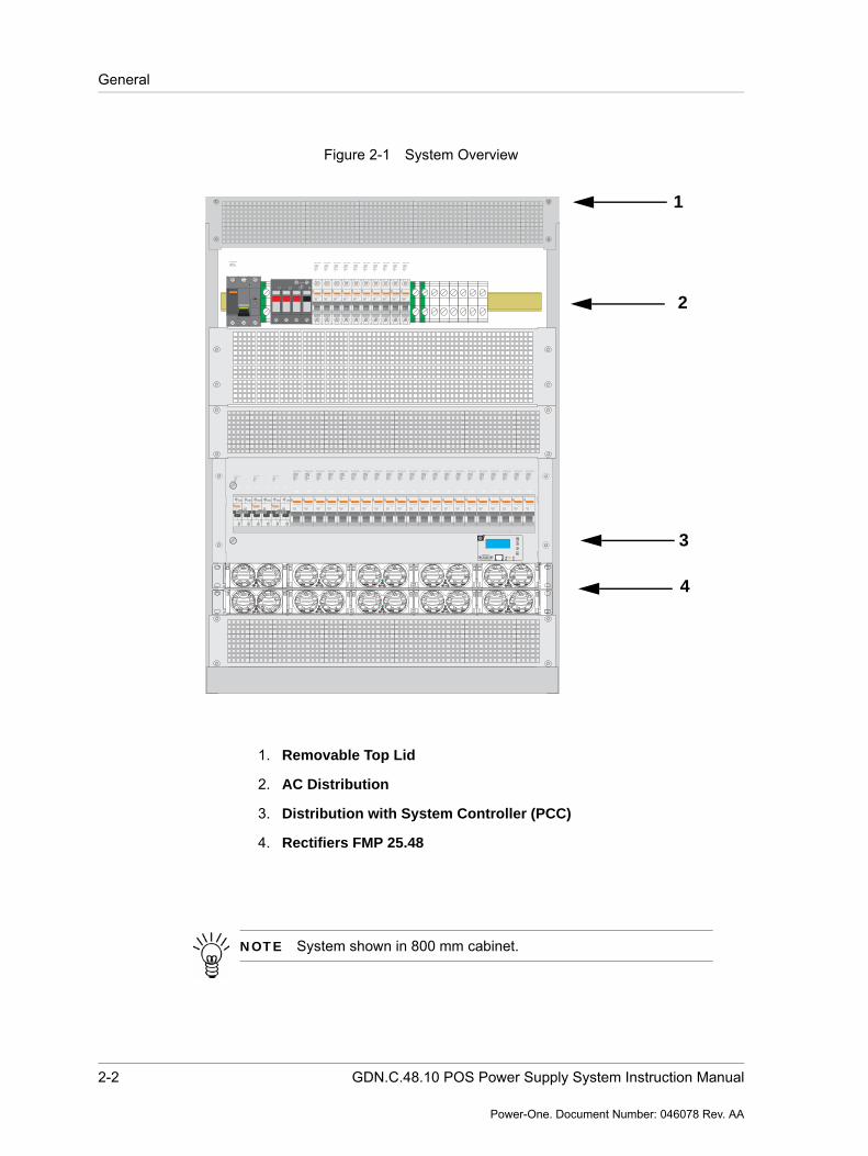
Figure 2-1 System Overview
1. Removable Top Lid
2. AC Distribution
3. Distribution with System Controller (PCC)
4. Rectifiers FMP 25.48
1
2
3
4
multi 9
C120ND100
MERLIN GERIN
415V
10000
I ONI ON I ONI ON
1
2
3
4
multi 9
C120ND100
MERLIN GERIN
415V
10000
I ONI ON I ONI ON
1
2
3
4
multi 9
C120ND100
MERLIN GERIN
415V
10000
I ONI ON I ONI ON
multi 9
C60NC16230/400V6000
3
MERLIN GERIN
I ONI ON
multi 9
C60NC16230/400V6000
3
MERLIN GERIN
I ONI ON
multi 9
C60NC16230/400V6000
3
MERLIN GERIN
I ONI ON
multi 9
C60NC16230/400V6000
3
MERLIN GERIN
I ONI ON
multi 9
C60NC16230/400V6000
3
MERLIN GERIN
I ONI ON
multi 9
C60NC16230/400V6000
3
MERLIN GERIN
I ONI ON
multi 9
C60NC16230/400V6000
3
MERLIN GERIN
I ONI ON
multi 9
C60NC16230/400V6000
3
MERLIN GERIN
I ONI ON
multi 9
C60NC16230/400V6000
3
MERLIN GERIN
I ONI ON
multi 9
C60NC16230/400V6000
3
MERLIN GERIN
I ONI ON
multi 9
C60NC16230/400V6000
3
MERLIN GERIN
I ONI ON
multi 9
C60NC16230/400V6000
3
MERLIN GERIN
I ONI ON
multi 9
C60NC16230/400V6000
3
MERLIN GERIN
I ONI ON
multi 9
C60NC16230/400V6000
3
MERLIN GERIN
I ONI ON
multi 9
C60NC16230/400V6000
3
MERLIN GERIN
I ONI ON
multi 9
C60NC16230/400V6000
3
MERLIN GERIN
I ONI ON
multi 9
C60NC16230/400V6000
3
MERLIN GERIN
I ONI ON
multi 9
C60NC16230/400V6000
3
MERLIN GERIN
I ONI ON
multi 9
C60NC16230/400V6000
3
MERLIN GERIN
I ONI ON
multi 9
C60NC16230/400V6000
3
MERLIN GERIN
I ONI ON
multi 9
C60NC16230/400V6000
3
MERLIN GERIN
I ONI ON
i
I ONI ON
multi 9
NG125L
MERLIN GERIN
0 OFF0 OFF
L1 L2 L3 N
multi 9
C60NC16230/400V6000
3
MERLIN GERIN
I ONI ON
multi 9
C60NC16230/400V6000
3
MERLIN GERIN
I ONI ON
multi 9
C60NC16230/400V6000
3
MERLIN GERIN
I ONI ON
multi 9
C60NC16230/400V6000
3
MERLIN GERIN
I ONI ON
multi 9
C60NC16230/400V6000
3
MERLIN GERIN
I ONI ON
multi 9
C60NC16230/400V6000
3
MERLIN GERIN
I ONI ON
multi 9
C60NC16230/400V6000
3
MERLIN GERIN
I ONI ON
multi 9
C60NC16230/400V6000
3
MERLIN GERIN
I ONI ON
multi 9
C60NC16230/400V6000
3
MERLIN GERIN
I ONI ON
multi 9
C60NC16230/400V6000
3
MERLIN GERIN
I ONI ON
1
2
4
3
NOTE System shown in 800 mm cabinet.
System Description 2-3
Power-One. Document Number: 046078 Rev. AA
Technical Data
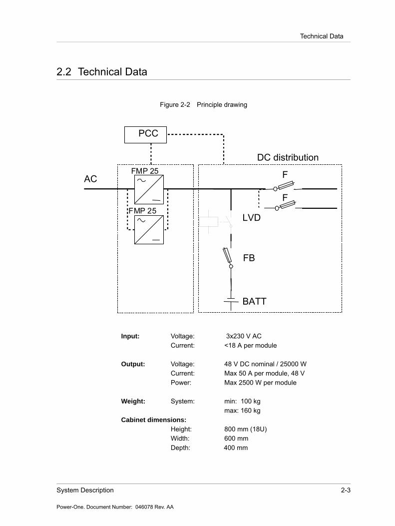
2.2 Technical Data
Figure 2-2 Principle drawing
Input: Voltage: 3x230 V ACCurrent: <18 A per module
Output: Voltage: 48 V DC nominal / 25000 WCurrent: Max 50 A per module, 48 VPower: Max 2500 W per module
Weight: System: min: 100 kgmax: 160 kg
Cabinet dimensions:
Height: 800 mm (18U)Width: 600 mmDepth: 400 mm
FB
BATT
LVD
F
F
DC distribution
ACFMP 25
FMP 25
PCC
2-4 GDN.C.48.10 POS Power Supply System Instruction Manual
Power-One. Document Number: 046078 Rev. AA
Operation
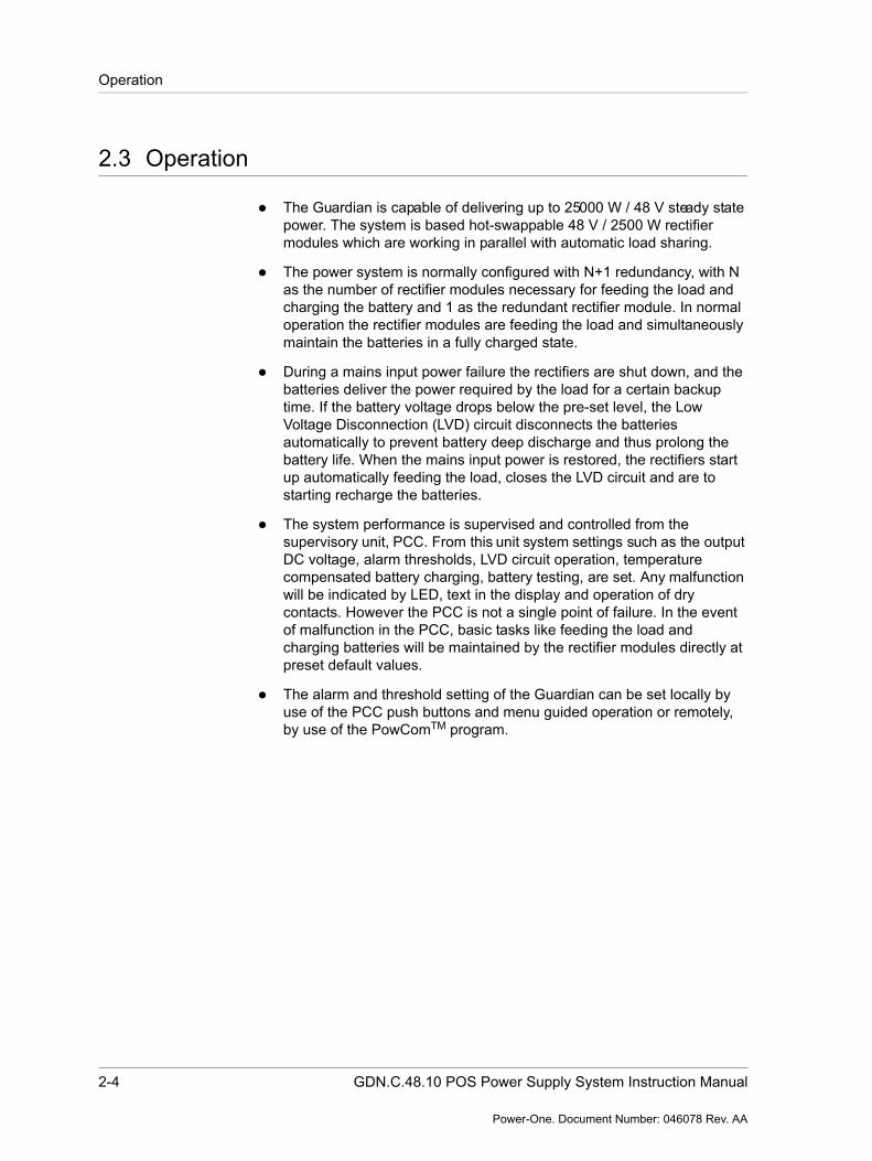
2.3 Operation
The Guardian is capable of delivering up to 25000 W / 48 V steady state power. The system is based hot-swappable 48 V / 2500 W rectifier modules which are working in parallel with automatic load sharing.
The power system is normally configured with N+1 redundancy, with N as the number of rectifier modules necessary for feeding the load and charging the battery and 1 as the redundant rectifier module. In normal operation the rectifier modules are feeding the load and simultaneously maintain the batteries in a fully charged state.
During a mains input power failure the rectifiers are shut down, and the batteries deliver the power required by the load for a certain backup time. If the battery voltage drops below the pre-set level, the Low Voltage Disconnection (LVD) circuit disconnects the batteries automatically to prevent battery deep discharge and thus prolong the battery life. When the mains input power is restored, the rectifiers start up automatically feeding the load, closes the LVD circuit and are to starting recharge the batteries.
The system performance is supervised and controlled from the supervisory unit, PCC. From this unit system settings such as the output DC voltage, alarm thresholds, LVD circuit operation, temperature compensated battery charging, battery testing, are set. Any malfunction will be indicated by LED, text in the display and operation of dry contacts. However the PCC is not a single point of failure. In the event of malfunction in the PCC, basic tasks like feeding the load and charging batteries will be maintained by the rectifier modules directly at preset default values.
The alarm and threshold setting of the Guardian can be set locally by use of the PCC push buttons and menu guided operation or remotely, by use of the PowComTM program.
System Description 2-5
Power-One. Document Number: 046078 Rev. AA
System Overview
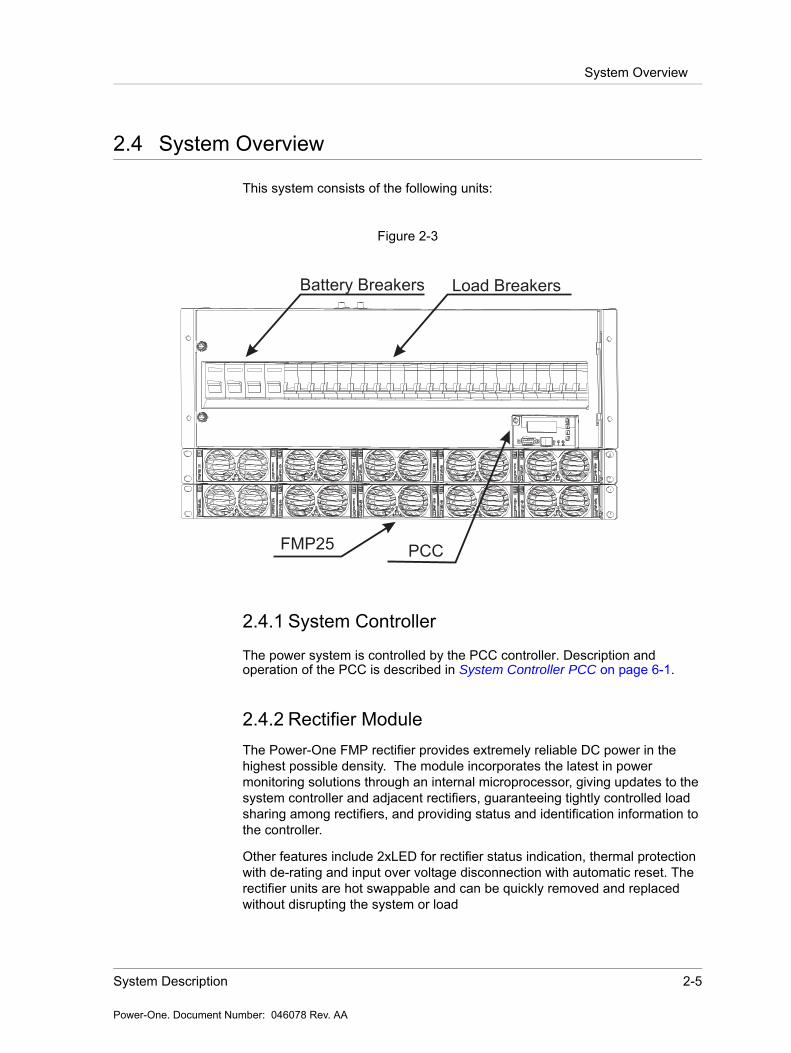
2.4 System Overview
This system consists of the following units:
Figure 2-3
2.4.1 System Controller
The power system is controlled by the PCC controller. Description andoperation of the PCC is described in System Controller PCC on page 6-1.
2.4.2 Rectifier ModuleThe Power-One FMP rectifier provides extremely reliable DC power in the highest possible density. The module incorporates the latest in power monitoring solutions through an internal microprocessor, giving updates to the system controller and adjacent rectifiers, guaranteeing tightly controlled load sharing among rectifiers, and providing status and identification information to the controller.
Other features include 2xLED for rectifier status indication, thermal protection with de-rating and input over voltage disconnection with automatic reset. The rectifier units are hot swappable and can be quickly removed and replaced without disrupting the system or load
Battery Breakers Load Breakers
FMP25 PCC
2-6 GDN.C.48.10 POS Power Supply System Instruction Manual
Power-One. Document Number: 046078 Rev. AA
System Overview
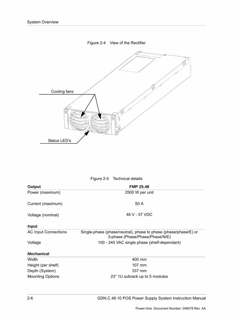
Figure 2-4 View of the Rectifier
Figure 2-5 Technical details
Cooling fans
Status LED’s
Output FMP 25.48
Power (maximum) 2500 W per unit
50 A
46 V - 57 VDC
Current (maximum)
Voltage (nominal)
Input
AC Input Connections Single-phase (phase/neutral), phase to phase (phase/phase/E) or 3-phase (Phase/Phase/Phase/N/E)
Voltage 100 - 240 VAC single phase (shelf-dependant)
Mechanical
Width 400 mm Height (per shelf) 107 mmDepth (System) 337 mmMounting Options 23” 1U subrack up to 5 modules
System Description 2-7
Power-One. Document Number: 046078 Rev. AA
System Overview
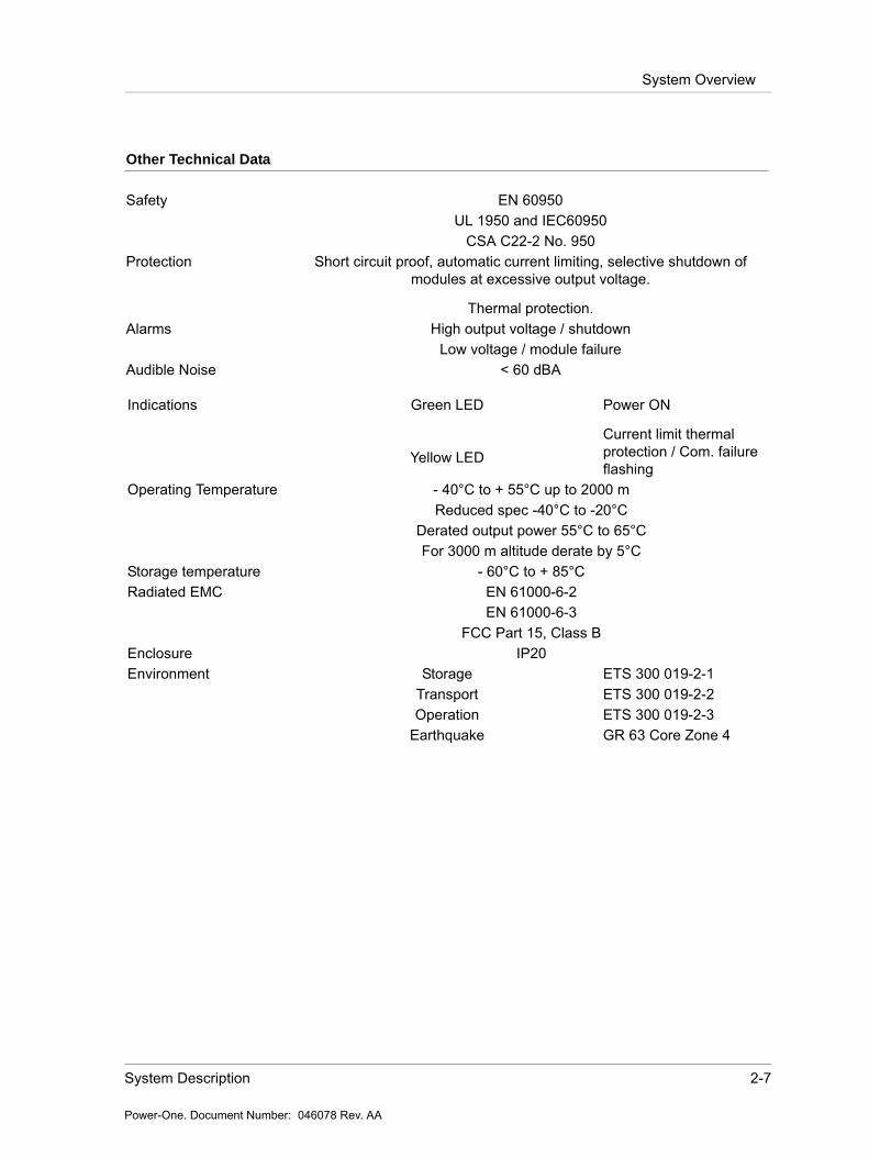
Other Technical Data
Safety EN 60950UL 1950 and IEC60950
CSA C22-2 No. 950Protection Short circuit proof, automatic current limiting, selective shutdown of
modules at excessive output voltage.
Thermal protection.Alarms High output voltage / shutdown
Low voltage / module failureAudible Noise < 60 dBA
Indications Green LED
Yellow LED
Power ON
Current limit thermal protection / Com. failure flashing
Operating Temperature - 40°C to + 55°C up to 2000 mReduced spec -40°C to -20°C
Derated output power 55°C to 65°CFor 3000 m altitude derate by 5°C
Storage temperature - 60°C to + 85°CRadiated EMC EN 61000-6-2
EN 61000-6-3FCC Part 15, Class B
Enclosure IP20Environment Storage ETS 300 019-2-1
Transport ETS 300 019-2-2Operation ETS 300 019-2-3
Earthquake GR 63 Core Zone 4

2-8 GDN.C.48.10 POS Power Supply System Instruction Manual
Power-One. Document Number: 046078 Rev. AA
System Overview
2.4.3 Rectifier SubrackThe Subrack for 5 FMP 25 is a shelf for interconnecting of FMP 25 rectifier modules. Each rectifier shelf has 5 rectifier positions, numbered from left to right viewed from the front.
Each rectifier shelf may be equipped according to present power requirements, and later be completed with additional FMP modules.
Figure 2-6 Front view of the subrack
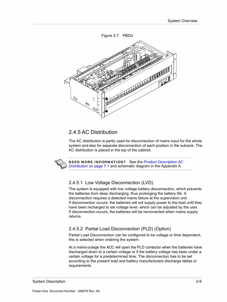
2.4.4 PBDU 23” - Distribution moduleThe Power-One PBDU includes a complete system controller plus battery and load distribution in a 4U unit. The Compact Distribution is compatible with various types of Power-One subracks/rectifier shelves, and may be configured for a variety of battery and load breaker selections as it is shown Figure 2-7.
The distribution unit is designed for switching the battery and load on and off. All DC distribution breakers are supervised by measuring voltage drop across each breaker. MCB's (breakers) which are not connected to any load will not cause breaker alarm even if they are left open.
Due to a small leakage current (2,5 - 3 mA) through the alarm circuit the voltage measured with a Digital Volt Meter (DVM) on an open breaker output, will be nearly equal to output rectifier voltage. If a battery breaker fault occurs or is simulated it might take from 2 - 10 minutes before the fault is indicated, depending on the battery condition.
System Description 2-9
Power-One. Document Number: 046078 Rev. AA
System Overview
Figure 2-7 PBDU
2.4.5 AC DistributionThe AC distribution is partly used for disconnection of mains input for the whole system and also for separate disconnection of each position in the subrack. The AC distribution is placed in the top of the cabinet.
2.4.5.1 Low Voltage Disconnection (LVD)The system is equipped with low voltage battery disconnection, which prevents the batteries from deep discharging, thus prolonging the battery life. A disconnection requires a detected mains failure at the supervision unit. .If disconnection occurs, the batteries will not supply power to the load until they have been recharged to set voltage level, which can be adjusted by the user.If disconnection occurs, the batteries will be reconnected when mains supply returns.
2.4.5.2 Partial Load Disconnection (PLD) (Option)Partial Load Disconnection can be configured to be voltage or time dependent, this is selected when ordering the system.
At a mains outage the ACC will open the PLD contactor when the batteries have discharged down to a certain voltage or if the battery voltage has been under a certain voltage for a predetermined time. The disconnection has to be set according to the present load and battery manufacturers discharge tables or requirements.
NEED MORE INFORMATION? See the Product Description AC Distribution on page 7-1 and schematic diagram in the Appendix A.

2-10 GDN.C.48.10 POS Power Supply System Instruction Manual
Power-One. Document Number: 046078 Rev. AA
System Overview

System Safety 3-1
Power-One. Document Number: 039126.fm Rev. AC1
Chapter 3 System Safety
3.1 Safety Warnings and Guidelines
The following warnings and guidelines should be followed by properly trained and authorized personnel when installing, operating, commissioning or maintaining this equipment. Neglecting the instructions may be dangerous to personnel and equipment.
3.1.1 System MarkingsThe following markings are found on the Power System:
Ground Symbol
DC Ground Symbol
Product Label - The product label contains the system part number, model number and system rating. The label is located inside the system.
Safety Label - The safety label is located inside the system.
3-2 GDN.S.00.10 POS Power Supply System User Guide
Power-One. Document Number: 039126.fm Rev. AC1
Safety Warnings and Guidelines
3.1.2 Safety RecommendationsAny device that uses electricity requires proper guidelines to ensure safety.
The Power System should only be installed or serviced by qualified personnel.
Always keep tools away from walkways and aisles. Tools present a tripping hazard in confined areas.
Keep the system area clear and dust-free during and after the installation.
Always know the location of emergency shut-off switches in case of an accident.
Always wear appropriate eye protection and use appropriate tools for working with high voltage equipment.
Do not perform any action that creates a potential hazard to other people in the system area.
Never work alone in potentially hazardous conditions. Always check for possible hazards before beginning work. Remove watches, rings and jewelry that may present a hazard while
working on the power system.
3.1.3 Installation WarningThe following safety guidelines should be observed when transporting or moving the system to the install location:
Before moving the Power System, read the system specifications sheet to determine whether the install site meets all the size, environmental, and power requirements.
The system should only be moved by qualified personnel and equipment. The Power System should be properly mounted to the building structure
at the install location to prevent bodily injury. Installation of the equipment in the rack should be properly installed so
that hazardous conditions are not present due to uneven loading. When installing the system in a rack, allow adequate room to prevent
blocking of the vent openings on the power equipment and to allow for optimal air circulation and to reduce the chance of system overheating.
3.1.4 Restricted Access Area WarningsThe Power System should be installed in a restricted access area. A restricted area is an area that can only be accessed by trained service personnel.
System Safety 3-3
Power-One. Document Number: 039126.fm Rev. AC1
Safety Warnings and Guidelines
3.1.5 Operating Temperature WarningsTo prevent the Power System from overheating, an automatic shutdown mechanism has been installed. It is not recommended to continually operate the Power System in an area that exceeds the maximum recommended operating temperature.
3.1.6 Electrical Safety WarningsThe following are electrical safety recommendations for working near the Power System:
Remove all metallic jewelry like watches or rings that may present a hazard while working on the power system.
Before connecting the AC input source to the power system, always verify voltage.
Verify the AC source capacity. See system specifications for AC information.
All AC connections must meet the National Electrical Code (NEC) and must conform to all local codes.
When making AC connections, all AC power and DC load distribution breakers should be in the OFF position.
All circuit breakers should meet the original design specifications of the system. In addition, equipment connected to the system should not overload the circuit breakers which may have a negative effect on overcurrent protection and supply wiring, causing system or user harm.
Verify the DC capacity before making connections. See system specifications for DC information.
NOTE This may be disregarded for systems delivered in a Power-One Outdoor enclosure.
WARNING Observe low voltage safety precautions before attempting to work on the system when power is connected. Potentially lethal voltages are present within the system.
WARNING Caution must be exercised when handling system power cables. Damage to the insulation or contact points of cables can cause contact with lethal voltages. For safety reasons, cables should be connected to the power system before power is applied.

3-4 GDN.S.00.10 POS Power Supply System User Guide
Power-One. Document Number: 039126.fm Rev. AC1
Safety Warnings and Guidelines
Potentially lethal voltages are present within the system. Ensure that all power supplies are completely isolated by setting all power switches to OFF, disconnecting all relevant connectors and removing all relevant breakers before attempting any maintenance work. Do not rely on switches alone to isolate a power supply. Batteries should also be disconnected.
Potentially lethal voltages are present within this system. Ensure that low voltage safety requirements are implemented before attempting to work on the system with power connected.
Potentially lethal voltages can be induced if the equipment is not grounded (earthed) correctly. Ensure that all ground connections are secure.
3.1.7 Grounding
3.1.8 Batteries
3.1.8.1 Lead Acid Batteries
Ensure the following guidelines are observed when dealing with equipment that may contain lead acid batteries:
WARNING The system should be hard-wired to the incoming earth ground. A solid high current ground connection capable of sinking the maximum system current is required.
WARNING A conductor is connected between the ground point and the 0 V DC busbar of the system/ cabinet. This conductor is connected to its own earth bar and not shared with other safety conductors.
WARNING When installing or replacing batteries, there is risk of explosion if an incorrect battery type is used.
WARNING This equipment may use Lead Acid Batteries. When handling batteries, follow the instructions included with the battery set, as the fluids contained within these batteries are known to be a health hazard. The disposal of lead acid batteries is subject to legal requirements for hazardous waste disposal. Local guidelines should be followed for disposal.
System Safety 3-5
Power-One. Document Number: 039126.fm Rev. AC1
Caution
Any attempt to burn these batteries may result in an explosion and the generation of toxic fumes.
Should a lead acid battery suffer damage, it must be moved into a well-ventilated area. Contact with the corrosive fluid must be avoided.
Neutralize any acid corrosion with copious amounts of a solution of baking soda and water, and then wipe off all traces of soda.
If the lead acid battery is removed from the equipment, any exposed contact must be insulated prior to disposal.
Ensure that protective full-face shields, rubber gloves and aprons are worn and insulated tools are used when working with the batteries. It is advised also to have water available in case acid gets in contact with the eyes.
3.1.9 In Case of an AccidentIn the event of an accident resulting in injury:
1. Use caution and check for hazards in the area.2. Disconnect power to the system.3. If possible, send someone to get medical aid. If not, check the condition
of the victim and call for help.
3.2 Caution
3.2.1 Storage and Transportation
3.2.2 Disposal
CAUTION During storage and transportation, the units must remain in their original packages in order to avoid mechanical damage, maintain tracability, and protect the units against electrostatic discharge.
CAUTION The product should not be disposed with other wastes at the end of its working life so as to prevent possible harm to the environment or human health from uncontrolled waste disposal.
3-6 GDN.S.00.10 POS Power Supply System User Guide
Power-One. Document Number: 039126.fm Rev. AC1
Caution
3.2.3 Handling Electrostatic Sensitive Devices
3.2.4 Traceability
3.2.5 Breakers
3.2.6 Hot Surfaces
CAUTION An electrostatic sensitive device is an electronic component that may be permanently damaged by the discharge of electrostatic charges encountered in routine handling, testing and transportation.
CAUTION Units are labelled with permanently attached product identification labels. The labels are designed to be indelible throughout the life span of the equipment, unless mistreated. Make sure that the product identification labels are present on the equipment and are not subjected to unusual wear or mistreatment.
CAUTION Breakers should always be replaced with the same type and rating in order to avoid damage to system components.
CAUTION Areas of the Power System may become hot. Take precautions and handle with care to avoid bodily harm.
Installation Guide 4-1
Power-One. Document Number: 046079.fm Rev. AA
Chapter 4 Installation Guide
4.1 Preface
The Guardian power system is optimized for international markets. A typical configuration is shown with up to 25 kW, site controller and DC distribution. Options include low voltage battery, AC surge protection and various AC and DC load distribution options. This procedure describes installation of all system opportunities.
4.2 Unpacking
Check that the received equipment is in accordance with the packing list. Ensure that the cabinet and the equipment have not been damaged during transportation.
You must report any parts that are damaged, missing or incorrect. If possible, correct the problem before continuing.
WARNING There are potential hazards related to installing this power system. It is important to carefully read and understand the contents of the Safety chapter before performing system installation.
4-2 GDN.C.48.10 POS Power Supply System Instruction Manual
Power-One. Document Number: 046079.fm Rev. AA
Tools required
4.3 Tools required
The following tools are required for a safe installation of the system:
Anti-static hand strap
Socket wrench, insulated
Screwdriver set, flat, insulated
Screwdriver set, torx, insulated
Screwdrivers, pozidrive (cross head), sizes 1, 2, and 3, insulated
Torque spanner (for battery connection), insulated
WARNING Use only single-ended, fully insulated tools. Shafts of for example screwdrivers should be insulated.
CAUTION Care must be taken when installing this system. The units can be damaged and can cause damage if not handled with care. Pay particular attention to the order in which units are installed.
Installation Guide 4-3
Power-One. Document Number: 046079.fm Rev. AA
Installation Procedure
4.4 Installation Procedure
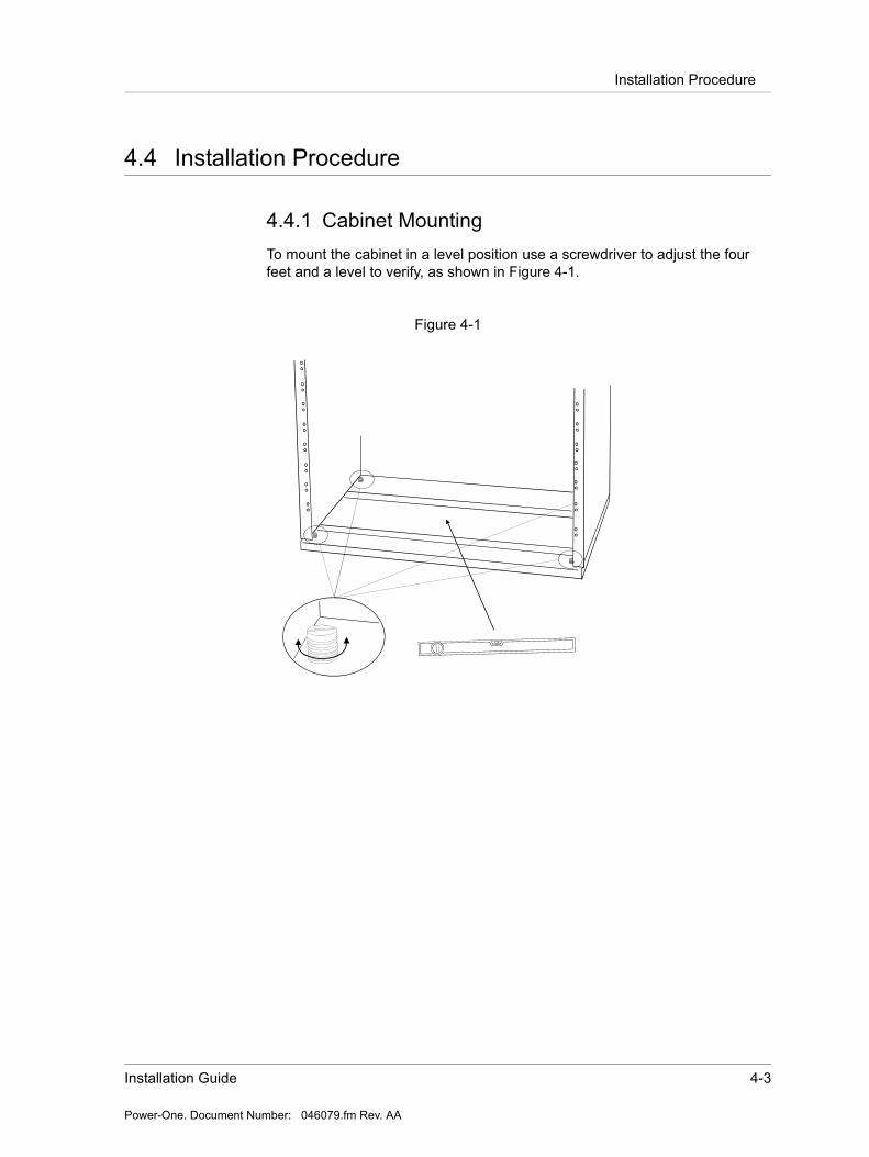
4.4.1 Cabinet MountingTo mount the cabinet in a level position use a screwdriver to adjust the four feet and a level to verify, as shown in Figure 4-1.
Figure 4-1
4-4 GDN.C.48.10 POS Power Supply System Instruction Manual
Power-One. Document Number: 046079.fm Rev. AA
Installation Procedure
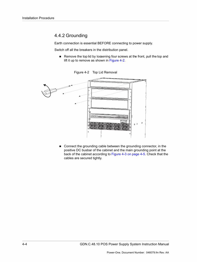
4.4.2 GroundingEarth connection is essential BEFORE connecting to power supply.
Switch off all the breakers in the distribution panel.
Remove the top lid by loosening four screws at the front, pull the top and lift it up to remove as shown in Figure 4-2.
Figure 4-2 Top Lid Removal
Connect the grounding cable between the grounding connector, in the positive DC busbar of the cabinet and the main grounding point at the back of the cabinet according to Figure 4-3 on page 4-5. Check that the cables are secured tightly.
Installation Guide 4-5
Power-One. Document Number: 046079.fm Rev. AA
Installation Procedure
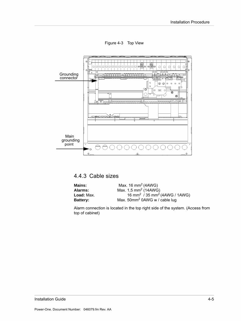
Figure 4-3 Top View
4.4.3 Cable sizesMains: Max. 16 mm2 (4AWG)Alarms: Max. 1,5 mm2 (14AWG)Load: Max. 16 mm2 / 35 mm2 (4AWG / 1AWG)Battery: Max. 50mm2 0AWG w / cable lug
Alarm connection is located in the top right side of the system. (Access from top of cabinet)
Groundingconnector
Maingrounding
point
4-6 GDN.C.48.10 POS Power Supply System Instruction Manual
Power-One. Document Number: 046079.fm Rev. AA
Installation Procedure
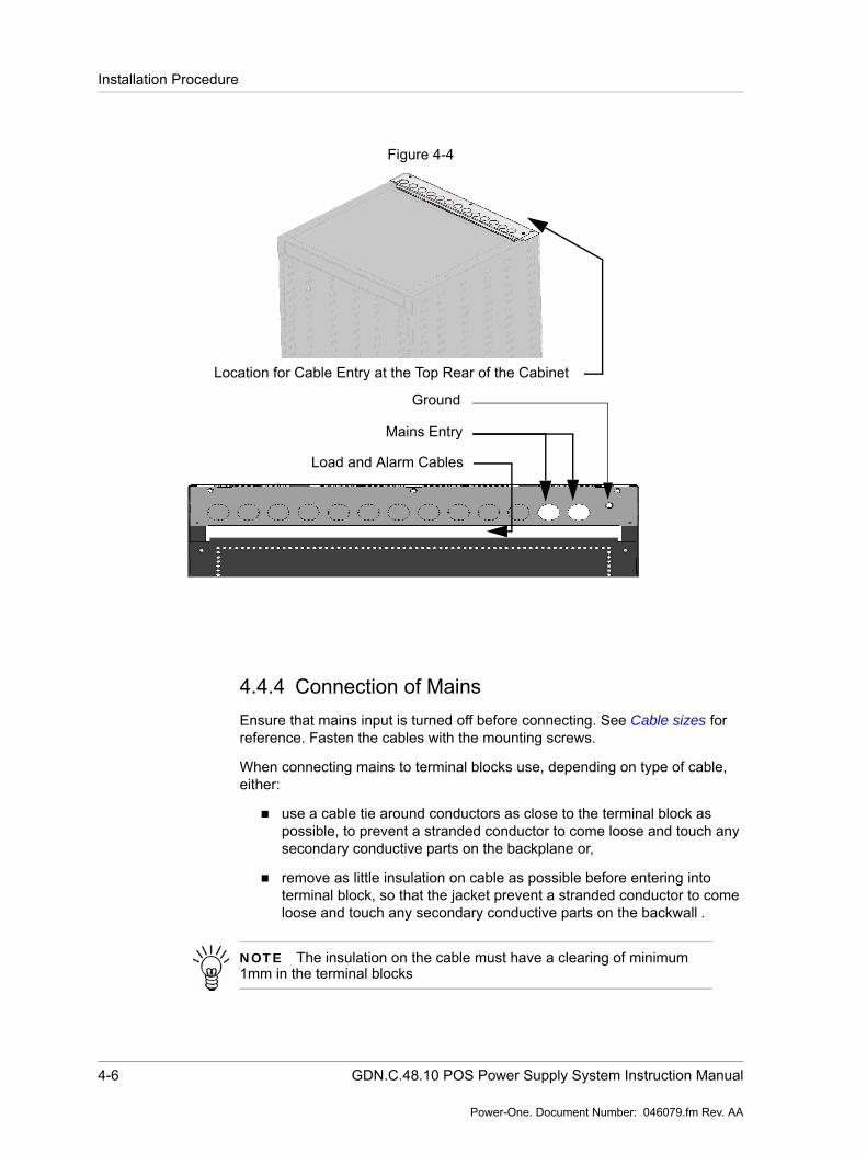
Figure 4-4
4.4.4 Connection of MainsEnsure that mains input is turned off before connecting. See Cable sizes for reference. Fasten the cables with the mounting screws.
When connecting mains to terminal blocks use, depending on type of cable, either:
use a cable tie around conductors as close to the terminal block as possible, to prevent a stranded conductor to come loose and touch any secondary conductive parts on the backplane or,
remove as little insulation on cable as possible before entering into terminal block, so that the jacket prevent a stranded conductor to come loose and touch any secondary conductive parts on the backwall .
Location for Cable Entry at the Top Rear of the Cabinet
Load and Alarm Cables
Mains Entry
Ground
NOTE The insulation on the cable must have a clearing of minimum 1mm in the terminal blocks

Installation Guide 4-7
Power-One. Document Number: 046079.fm Rev. AA
Installation Procedure
The mains input terminal blocks can be connected to 3x400 V AC.
Use Torque table in the Maintenance and Troubleshooting Chapter for the correct torque.
Figure 4-5
Recommended mains fuse:
400 V 3-phase, 5 wire only: Triple pole 63 A C-char (Mains 1)
PE
3x400V AC
7 6 5 4 3 2 1 1
NL1L2L3 PE
PE
3x230V AC
7 6 5 4 3 2 1 1
L2 PEL1L3

4-8 GDN.C.48.10 POS Power Supply System Instruction Manual
Power-One. Document Number: 046079.fm Rev. AA
Installation Procedure
4.4.5 Alarm ConnectionFor remote supervision of the alarms, there are 4 potential free alarm contacts. Each alarm contact represents different alarm conditions. See “Appendix B - Configuration” for an alarm overview. Potential free alarm contacts for remote signalling at PBDU interface are located in the right side of the distribution.
Figure 4-6 Connection of Alarms
Alarm cabling installation:
The green connectors can be easily removed, if desired. For easy installation of the wires to the connector follow the steps below:
1. Remove the green plug from each connector.
2. Determine whether to reference normally closed or normally open with reference to common for each alarm contact.
3. Strip the wires back approximately 10 mm. Stranded wire may be soldered or covered with copper ferrule if desired.
NOTE Alarm contacts are shown in alarm position.
XC6
XC6
3
2
1
6
5
4
Alarm 3
Alarm 4
XC5
XC5
3
2
1
6
5
4
Alarm 1
Alarm 2
Installation Guide 4-9
Power-One. Document Number: 046079.fm Rev. AA
Installation Procedure
4. Insert wire into the correct positions in the green connector and tighten screw to clamp wire into connector.
5. Route the wires through the cable area at the top left of the cabinet.
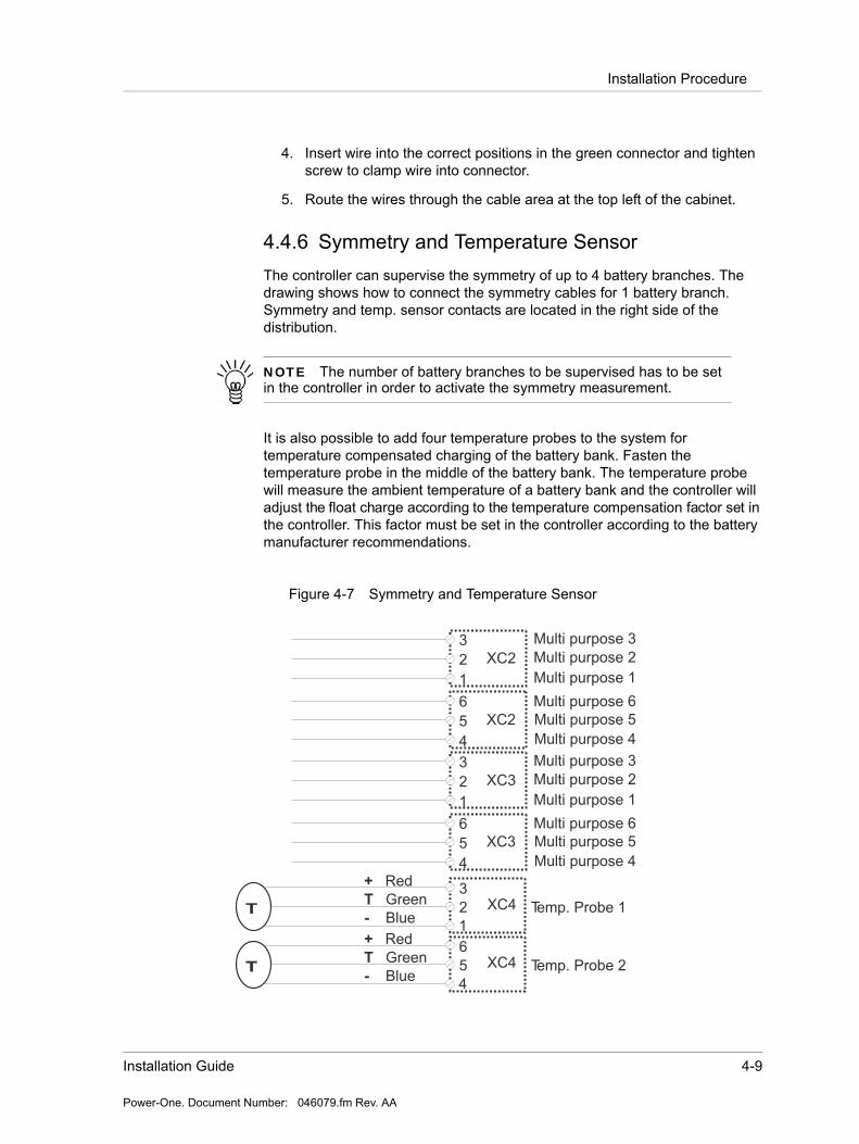
4.4.6 Symmetry and Temperature SensorThe controller can supervise the symmetry of up to 4 battery branches. The drawing shows how to connect the symmetry cables for 1 battery branch. Symmetry and temp. sensor contacts are located in the right side of the distribution.
It is also possible to add four temperature probes to the system for temperature compensated charging of the battery bank. Fasten the temperature probe in the middle of the battery bank. The temperature probe will measure the ambient temperature of a battery bank and the controller will adjust the float charge according to the temperature compensation factor set in the controller. This factor must be set in the controller according to the battery manufacturer recommendations.
Figure 4-7 Symmetry and Temperature Sensor
NOTE The number of battery branches to be supervised has to be set in the controller in order to activate the symmetry measurement.
+
-
Red
Blue
GreenTT
3
2
1
Temp. Probe 1
6
5
4
XC3
XC4
3
2
1
Multi purpose 6
XC3
Multi purpose 1
Multi purpose 2
Multi purpose 3
Multi purpose 5
Multi purpose 4
6
5
4
XC2
3
2
1
Multi purpose 6
XC2
Multi purpose 1
Multi purpose 2
Multi purpose 3
Multi purpose 5
Multi purpose 4
+
-
Red
Blue
GreenTT
6
5
4
Temp. Probe 2XC4
4-10 GDN.C.48.10 POS Power Supply System Instruction Manual
Power-One. Document Number: 046079.fm Rev. AA
Installation of Rectifiers
Installing the Symmetry cabling and the battery temperature sensor:
1. Remove the green plug from each connector.
2. Strip the wires back approximately 10mm. Stranded wire may be soldered or covered with copper ferrule if desired.
3. Insert wire into the correct positions in the green connector and tighten screw to clamp wire into connector.
4. The wires are winded up and pre-routed with fastener strips on the cabinet sidewall. The cables must be unwinded and connected to the battery pole according to Figure 4-9.
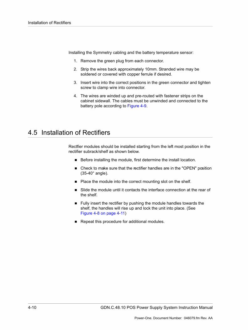
4.5 Installation of Rectifiers
Rectfier modules should be installed starting from the left most position in the rectifier subrack/shelf as shown below.
Before installing the module, first determine the install location.
Check to make sure that the rectifier handles are in the "OPEN" position (35-40° angle).
Place the module into the correct mounting slot on the shelf.
Slide the module until it contacts the interface connection at the rear of the shelf.
Fully insert the rectifier by pushing the module handles towards the shelf, the handles will rise up and lock the unit into place. (See Figure 4-8 on page 4-11)
Repeat this procedure for additional modules.

Installation Guide 4-11
Power-One. Document Number: 046079.fm Rev. AA
Installation of Rectifiers
Figure 4-8
1.
2.
3.
35- 40°
4-12 GDN.C.48.10 POS Power Supply System Instruction Manual
Power-One. Document Number: 046079.fm Rev. AA
Battery Connection
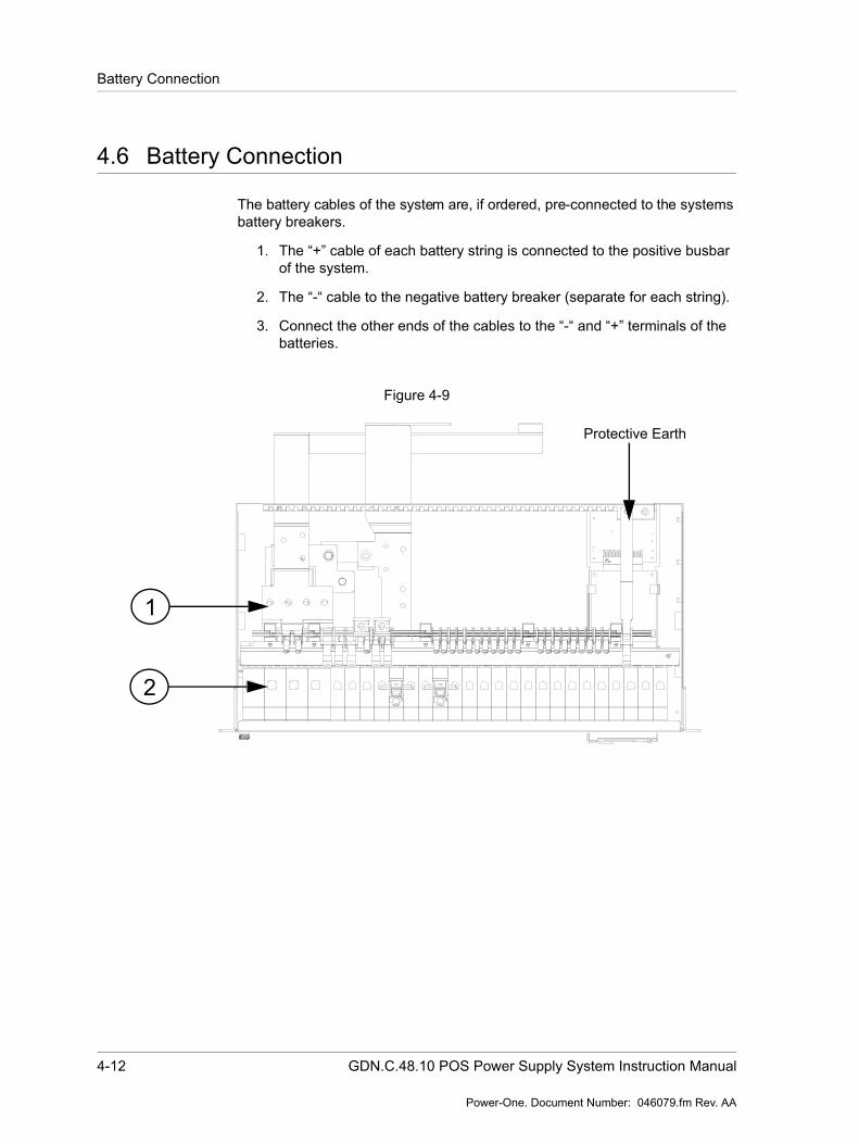
4.6 Battery Connection
The battery cables of the system are, if ordered, pre-connected to the systems battery breakers.
1. The “+” cable of each battery string is connected to the positive busbar of the system.
2. The “-“ cable to the negative battery breaker (separate for each string).
3. Connect the other ends of the cables to the “-“ and “+” terminals of the batteries.
Figure 4-9
2
1
Protective Earth

Installation Guide 4-13
Power-One. Document Number: 046079.fm Rev. AA
DC Connection
4.7 DC Connection
This section details how to connect external load to the DC load breakers.
Check that all the MCB’s are in the OFF position.
1. Connect the negative (-) DC supply cable to the appropriate negative DC distribution MCB by inserting the stripped cable in the opening on top of the MCB and tightening the screw. Make sure the cable has the correct rating for the selected MCB.
2. Connect the positive (+) DC supply cable directly to the positive bus bar by inserting the stripped cable to the hole on top of the screw connector so that the cable is behind the bus bar, and then tightening the screw. Start connecting the loads to the bus bar from the first connector on the left. Make sure, the cable is the correct rating for the load. Check, that all the cables are secured tightly to the connectors.
Use Torque table in the Maintenance and troubleshooting chapter for the correct torque.
Figure 4-10
2
1
Protective Earth
4-14 GDN.C.48.10 POS Power Supply System Instruction Manual
Power-One. Document Number: 046079.fm Rev. AA
DC Connection
Commissioning 5-1
Power-One. Document Number: 044188.fm Rev. AA
Chapter 5 Commissioning
5.1 Commissioning Overview
Before delivery the system was thoroughly inspected and tested. The following chapter is a guide to the set-up and operation of the control functions of the system.
If there are any difficulties in increasing the voltage to alarm level, the alarm level can be temporarily adjusted to a lower level.
NOTE Before starting commissioning read the product description for the individual components.
WARNING ONLY TECHNICAL STAFF WITH THE NECESSARY EXPERIENCE AND KNOWLEDGE, WITH REGARD TO THE POWER SUPPLY SUPPORT SYSTEM AND ITS BATTERIES, MAY PERFORM THE COMMISSIONING. IT IS IMPORTANT TO FOLLOW ALL SAFETY REGULATIONS.
5-2 GDN.C.48.M24 Power Supply System User Guide
Power-One. Document Number: 044188.fm Rev. AA
Tools and Test Equipment
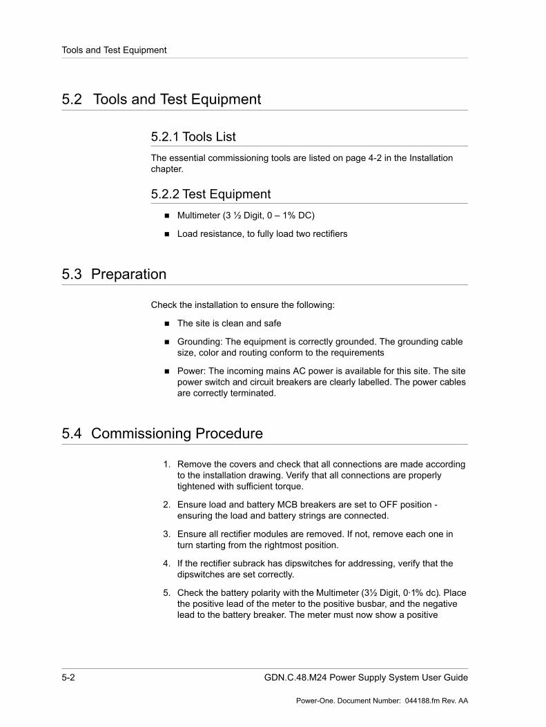
5.2 Tools and Test Equipment
5.2.1 Tools ListThe essential commissioning tools are listed on page 4-2 in the Installation chapter.
5.2.2 Test Equipment Multimeter (3 ½ Digit, 0 – 1% DC)
Load resistance, to fully load two rectifiers
5.3 Preparation
Check the installation to ensure the following:
The site is clean and safe
Grounding: The equipment is correctly grounded. The grounding cable size, color and routing conform to the requirements
Power: The incoming mains AC power is available for this site. The site power switch and circuit breakers are clearly labelled. The power cables are correctly terminated.
5.4 Commissioning Procedure
1. Remove the covers and check that all connections are made according to the installation drawing. Verify that all connections are properly tightened with sufficient torque.
2. Ensure load and battery MCB breakers are set to OFF position - ensuring the load and battery strings are connected.
3. Ensure all rectifier modules are removed. If not, remove each one in turn starting from the rightmost position.
4. If the rectifier subrack has dipswitches for addressing, verify that the dipswitches are set correctly.
5. Check the battery polarity with the Multimeter (3½ Digit, 0·1% dc). Place the positive lead of the meter to the positive busbar, and the negative lead to the battery breaker. The meter must now show a positive
Commissioning 5-3
Power-One. Document Number: 044188.fm Rev. AA
Commissioning Procedure
voltage. If the voltage is negative, change over the connection of the blue and black battery cables to the batteries.
6. Turn on the AC mains voltage.
7. Measure the AC voltage on the AC terminal block, between phases and neutral. The correct value is approximately 230 V. If the value is different, check the AC connection.
8. Plug in all rectifier modules, starting from the leftmost position. Make sure to fasten the rectifiers again. The rectifiers will turn on automatically.
9. Set load breakers into "1" (ON) position.
10. Verify right polarity on battery connection by measuring the voltage drop across battery breaker(s) (Normally not more than 5 VDC)
11. Green LED on controller should blink for approximately 20 sec.
12. Output voltage will increase slowly to U1.
13. Turn battery breaker to "1" ("on") position.
14. If any alarms are present, they should be reset in accordance with "Show alarms" in product description controller.
15. The system should now be without alarms.
16. Attach all the system covers in their correct places.
17. Check that all changes to drawings, if any have been completed.
18. Clean the site.
19. Fill in the commissioning record (see end of chapter).
5-4 GDN.C.48.M24 Power Supply System User Guide
Power-One. Document Number: 044188.fm Rev. AA
Test of output voltage
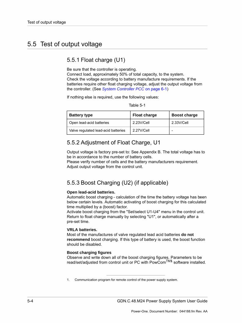
5.5 Test of output voltage
5.5.1 Float charge (U1)Be sure that the controller is operating.Connect load, approximately 50% of total capacity, to the system.Check the voltage according to battery manufacture requirements. If the batteries require other float charging voltage, adjust the output voltage from the controller. (See System Controller PCC on page 6-1)
If nothing else is required, use the following values:
Table 5-1
5.5.2 Adjustment of Float Charge, U1Output voltage is factory pre-set to: See Appendix B. The total voltage has to be in accordance to the number of battery cells.Please verify number of cells and the battery manufacturers requirement.Adjust output voltage from the control unit.
5.5.3 Boost Charging (U2) (if applicable)Open lead-acid batteries. Automatic boost charging - calculation of the time the battery voltage has been below certain levels. Automatic activating of boost charging for this calculated time multiplied by a (boost) factor.Activate boost charging from the "Set/select U1-U4" menu in the control unit.Return to float charge manually by selecting "U1", or automatically after a pre-set time.
VRLA batteries.Most of the manufactures of valve regulated lead acid batteries do not recommend boost charging. If this type of battery is used, the boost function should be disabled.
Boost charging figuresObserve and write down all of the boost charging figures. Parameters to be read/set/adjusted from control unit or PC with PowComTM1 software installed.
Battery type Float charge Boost charge
Open lead-acid batteries 2.23V/Cell 2.33V/Cell
Valve regulated lead-acid batteries 2.27V/Cell -
1. Communication program for remote control of the power supply system.
Commissioning 5-5
Power-One. Document Number: 044188.fm Rev. AA
Battery Supervision
5.6 Battery Supervision
For systems with symmetry cables supplied:
Set number of battery strings according to number of battery strings in the system. The settings are to be made in the control unit via a PC with PowComTM software installed or directly in the controller (if symmetry failure is indicated).
The symmetry fault alarm is to be simulated by pulling out one symmetry cable from the battery string. Measure that setting to make sure that it is in accordance with battery manufacturer recommendations.
For systems with temperature probe cable supplied:
The temperature compensation is factory pre-set. Check that the temperature probe is activated and verify that the compensation level is according to battery manufacturer requirements. (If no compensation level is available from the battery manufacture Power-One recommends it to be set to 0,5 V).
5.7 Battery test
The settings should be made according to battery manufacturer requirements, but as a rule of thumb the following settings can be used for standard VR lead batteries:
No. of test pr. year = 2U3 Test = 1,9 V/cellEnd voltage b.test = 1,94V/cellBatt. test time = 40% of expected backup timeAh limit for test = 40% of nominal battery capacity
Parameters are set/adjusted using the controller (Battery test menu) or "Supervision - Set parameters” menu in the PowComTM software.

5-6 GDN.C.48.M24 Power Supply System User Guide
Power-One. Document Number: 044188.fm Rev. AA
Commissioning record
5.8 Commissioning record
This is a step-by-step commissioning record for easy commissioning of Power-One Supply Systems. Do not continue if any faults occur during this commissioning. The checkpoints are to be considered as a minimum for commissioning of the system.
Table 5-2 Commissioning record
Checked
()
Result
1. Check that the rack is level2. Check that all breakers are turned to “off” position
and that no rectifiers are mounted in the subrack(s).
3. Connect AC, and measure voltage on the mains input connections in the cabinet, Is to be 230V AC (Measure 230V from phase to N when 400V mains input is used)
L1-N:………..V ACL2-N:...............V ACL3-N:...............V AC
4. Mount the rest of the rectifiers5. After connection of battery, verify right polarity by
measuring the voltage drop across the battery breakers (normally not more than 5V DC).
6. Check float charge, U1, and boost charge, U2. It is to be adjusted according to the battery manufacturers requirements.
U1:……..V DCU2:.........V DC
7. Check temperature compensation. It is to be adjusted according to the battery manufacture requirements.Check temperature read from the controller compared to the ambient temperature.
Comp. :…….V/10oC
Read off:………oC
8. Check symmetry measurement and set number of battery strings according to actual number of supervised battery strings in the system.
Number: ….
Alarm limit:……9. Check alarm transmission by running an alarm test.
System Controller PCC 6-1
Power-One. Document Number: 040178.fm Rev. AF
Chapter 6 System Controller PCC
6.1 General - Product description PCC w/Display
PCC - Prime Controller Card - is a supervisory system particularly designed for supervision of power supply systems based up on Power One rectifier modules. A RS485 data bus is used for internal communication with the rectifiers. RS232 serial interface for remote control from a PC with PowCom1 software.
For more detailed project specific information regarding system settings see Appendix B, Configuration. This document specifies all available standard Power-One alarms, i.e. alarm 0 up to 23 and any customer specific alarms (available as alarm 24 up to 39).
A complete supervision system always consist of the following units:
PCC- Main Controller Board With Front
This is the master unit in the system communicating with all distributed micro controllers. Features include LCD, visual alarm indication, RS232 contact for
1. PowCom is a communications software package that allows the remote control of the system. The software uses a Windows based interface to allow access to the PCS. PowCom is installed on a remote PC and can access the system by either direct connection, a LAN, or through a dial-up modem.
NOTE Some of the alarms have Power-One standard limits and some of them have customer specific adjusted limits.
6-2 Power Supply System Instruction Manual
Power-One. Document Number: 040178.fm Rev. AF
Technical specification:
remote operation and RS485 for internal communication with up to 20 rectifiers.
External and Internal Alarm Interface Boards
The alarm interface boards contain:
Input for current reading
Battery and load breaker monitoring
Battery temperature and battery symmetry measurement
Output for operating two individual contactors (LVD and PLD)
4 potential free alarm contacts.
2 multi purpose contacts for supervision of miscellaneous signals. These are configurable for customer needs but is set up for symmetry measurement by default.
6.2 Technical specification:
Input voltage: 18-60 V DC
Current: <200 mA at 48 V
Instrumentation: Three LED's, Green - OK, Yellow - Message, Red - Alarm. LCD Display with backlight
Interface: RS232 for remote operation via a PC. RS485 forinternal communication with 20 modules.
Basic functions: Simple menu-guided operationUser-selectable alarm parametersTemperature compensated chargingBoost charging, manual and automaticLVD control of two contactors, voltage or timecontrolledBattery test, manual or automatic with symmetry measurement. Alarm relay testSoftware controlled start up after mains outage and battery test
6.3 Operation - Introduction
The PCC communicates through an alarm interface board and a backplane that connects to the rectifier modules.
System Controller PCC 6-3
Power-One. Document Number: 040178.fm Rev. AF
Operation - Introduction
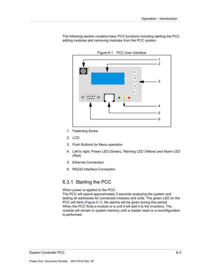
The following section contains basic PCC functions including starting the PCC, adding modules and removing modules from the PCC system.
Figure 6-1 PCC User Interface
1. Fastening Screw
2. LCD
3. Push Buttons for Menu operation
4. Left to right: Power LED (Green), Warning LED (Yellow) and Alarm LED (Red)
5. Ethernet Connection
6. RS232 Interface Connection
6.3.1 Starting the PCCWhen power is applied to the PCC:The PCC will spend approximately 5 seconds analyzing the system and testing all addresses for connected modules and units. The green LED on the PCC will blink (Figure 6-1). No alarms will be given during this period.When the PCC finds a module or a unit it will add it to the inventory. The module will remain in system memory until a master reset or a reconfiguration is performed.
i
12
3
4
5
6
6-4 Power Supply System Instruction Manual
Power-One. Document Number: 040178.fm Rev. AF
Operation - Introduction
6.3.2 Adding modulesWhen a rectifier is added to the system it will remain off until the PCC detects it.
1. The PCC constantly scan for new modules and units.
2. The PCC will locate the module, and the new module will give a current sharing fault until its output voltage has been adjusted to the correct voltage. This may take additional time.
6.3.3 Removing modulesPhysically removing a module from the system appears as a communication error on the PCC.
1. To remove the error message press the reconfigure button in the Inventory window in PowCom.
2. Make sure that there are no communication faults caused by any other failure before doing this as it will cause all non-communicating modules to be removed from the inventory.
3. This will make all communication faults disappear, but it will not fix any problems so it must only be used if the communication fault is caused by the module being intentionally removed.
6.3.4 PCC ControlThe control unit is equipped with four push buttons:
CANCEL - Used to go cancel the current selection on the menu hierarchy. When pressed the menu will return to the previous screen.
UP ARROW - Used to go up in the menu hierarchy. select options and to adjust limits.
DOWN ARROW - Used to go down in the menu hierarchy. select options and to adjust limits.
RETURN - Used to select and confirm an option or to go down a level in the PCC software hierarchy.
To adjust the alarm limits, use the arrow keys to select "adjust limits". Press RETURN to enter the sub menu, and RETURN once more to select "alarm limit". By using the arrow keys the various alarm limits can be checked. For adjusting a limit: select the correct limit and press RETURN. The correct password must be entered before a new value can be set.

System Controller PCC 6-5
Power-One. Document Number: 040178.fm Rev. AF
Operation - Introduction
The password is set to 1234 by default, but can be changed. Use the arrow keys to set and RETURN to confirm each digit. CANCEL can be used to correct a digit. For more information on setting the system password, see the section "Set New Password" in this chapter.
Adjust mode is indicated by a the edit icon being visible and a blinking cursor. Use the arrow keys to adjust the alarm limit and press RETURN to confirm the value or CANCEL to revert to the previous value.
To return to main menu, press the CANCEL button. If the PCC is left unattended the display will return to main menu automatically after 2 minutes.
6.3.5 PCC IconsThe top bar on the PCC display includes icons explaining status for various system parameters. This chapter describes these icons.
Figure 6-2 PCC Icons
Battery Icon
The battery icon displays the charge status for the batteries shown in 20% increments. The charge status is calculated from an accumulated amount of discharged Ah. It also takes into account the load current and the voltage to predict the remaining capacity.
During charging the battery icon will pulsate. During the final fill charge of the battery only the rightmost segment will blink.
After the system is started the first time it will take up to 48 hours before the battery icon is fully operational. The battery capacity must be set correctly in the Adjust Limits | Battery settings menu for the Icon to work properly. If the Battery capacity is set to 0 the icon is not shown.
+-
+-

6-6 Power Supply System Instruction Manual
Power-One. Document Number: 040178.fm Rev. AF
Operation - Introduction
NOTE The battery charge status may not be correct if the battery is malfunctioning.
Graph Icons
The graph icons indicate charging mode either Boost mode or Battery Test mode. The graph showing an upgoing curve is the Boost icon, while Battery Test is indicated with a downgoing curve on the graph.
Update Mode
This icon is displayed in editing mode when the user is accessing editable parameters in the menu tree. The values that can be updated can be accessed by pressing the enter button when the value is shown.
Warning and Alarm Icons
The Warning icon is present when a warning is present, while the alarm icon indicates an alarm situation.
Mains Failure Icon
This icon indicates mains failure.
7-segment Display
The 7-segment displays the system voltage with 2 decimal points (V).
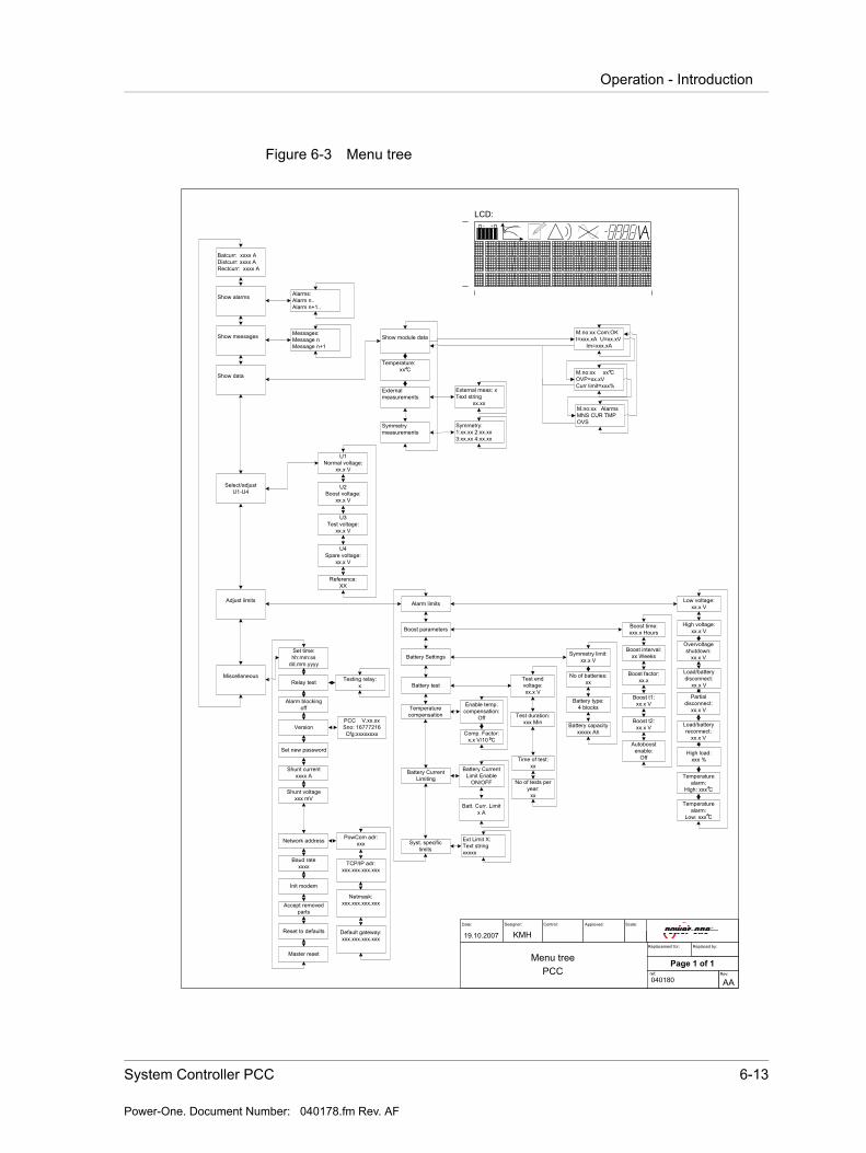
6.3.6 PCC MenusThe PCC menu is divided into nine sections. Some of these sections are further divided into more menu options. Figure 6-3 Menu tree shows the
Boost Test
Warning Alarm

System Controller PCC 6-7
Power-One. Document Number: 040178.fm Rev. AF
Operation - Introduction
hierarchy tree. The following section contains descriptions of each menu option.
6.3.6.1 Show voltage and currentsThe default PCC screen displays system voltage and battery current. Pressing the down arrow will display system voltage and distribution current, pressing down once more will display system voltage and rectifier current.
6.3.6.2 Show alarmsDisplays the current alarm status. If there are several alarms use the arrow keys to scroll through the alarms. Any new alarms or alarms that disappear will be added or taken off of the menu immediately. Battery failure and failure alarms need to be reset manually by pressing RETURN at the show alarms display.
6.3.6.3 Show messagesThis item displays any messages. If there are several messages use the arrow keys to view the various messages. New or disappearing messages will be updated immediately on the menu.
6.3.6.4 Show dataThis menu displays information about: modules, units, temperature, and symmetry voltage. Information on each of these menus is in the following section:
Module DataThis menu displays information from each rectifier module. Use the arrow keys to select the module number.
NOTE Rectifier modules are numbered from the top to bottom, and left to right.
Once the rectifier is selected on screen, Pressing RETURN will display a new menu with the following information: communication status, module current, mean current, module temperature, module measured voltage, Module OVP limit, alarm information.
Module alarms are indicated by 3 letter flags. The meanings of these are as follows.
MNS - No input mains.
LOW - Output voltage low (depends on rectifier type)
OFF - No operation, caused by no mains or other failure
6-8 Power Supply System Instruction Manual
Power-One. Document Number: 040178.fm Rev. AF
Operation - Introduction
OVS - Overvoltage shutdown
FAN - Fan failure, will cause the module turn off (depending on type of module.)
CUR - Current sharing fault. Current deviates too much from average
TMP - Temperature is high. This alarm must be reset manually
TemperatureThis menu displays the battery temperature.
Symmetry VoltageThe symmetry voltage for each battery branch is displayed.
6.3.6.5 Controller failureIn case the controller fails to operate all 4 alarm relays will be activated (In alarm position.)
6.3.6.6 Select / adjust U1 - U4This menu is used to select one of the references for the 4 charge modes, U1 - float voltage, U2 - boost voltage, U3 - battery test voltage, U4 - spare, and to adjust these references.
The voltage references can be adjusted in steps of 0,1V.
U1 Normal. The U1 reference is shown, press RETURN to change U1 (The float charge voltage) and use the arrow keys to adjust to the proper voltage.
U2 Boost. The U2 reference is shown, press RETURN to change U2 (The boost charge voltage).
U3 Test. The U3 reference is shown, press RETURN to change U3 (The Battery test voltage).
U4 Spare. The U4 reference is shown, press RETURN to change U4 (The spare voltage). The U4 setting is normally not used in this system.
CAUTION Always consult the battery user's guide before attempting to boost. Improper settings can damage batteries.
System Controller PCC 6-9
Power-One. Document Number: 040178.fm Rev. AF
Operation - Introduction
6.3.6.7 Adjust limitsThe Adjust Limits menu allows the user to change and add limits to the system. The menu has the following options: alarm limits, boost parameters, battery test, temperature compensation, battery current limit, system specific limits and distribution current limits. Parameters can be set and adjusted by selecting the different sub-menus.
Alarm limits.This menu allows the following alarm limits to be changed:
High voltage
Low voltage
Over voltage shutdown limit
Low voltage disconnect
Partial low voltage disconnect limits
Load reconnect limit
High load limit
High temperature limit.
Change these limits using the arrow keys and RETURN to select. See Appendix B, Configuration for default settings.
Boost parameters.This menu contains the limits for boost charging control. See section "Boost charging" for more information.
Battery settings.Additional setting for battery are number of branches, battery type, battery capacity and symmetry limit. Symmetry measuring is relevant with battery type where can be set number of blocks in each branch (2,3,4). Symmetry measuring point is between each block.
Battery test.This menu contains the limits for battery test. See section "Battery test" for more information.
6-10 Power Supply System Instruction Manual
Power-One. Document Number: 040178.fm Rev. AF
Operation - Introduction
Temperature comp.This menu turn the temperature compensation on and off, and is used to set the compensation factor.The temperature compensation factor is used to regulate the battery charging voltage according to high or low battery voltage. The compensation factor is added for each 10 degree change in battery temperature.
Application example:
System that includes 4 x 12 V batteries - 6 cells in each battery.
1 cell gives (example values from battery datasheet):
2.28 V/20°C
2.24 V/30°C
The difference between values at 20°C and 30°C makes 0.04 V / cell
6 x 0.04 V = 0.24 V /10°C - 6 cells in each battery
The battery string in this case comprises 4 x 12 V batteries to comprise a 48 V string. The compensation factor should be entered as a value for a full battery string. The correct compensation factor in this case will be:
4 x 0.24 V = 0,96 V /10°C
System specific limitsOnly available for specific systems. For more information see Appendix B, Configuration
Batt. Cur. Limit.This menu is used to toggle the battery current limiting on and off, and to set the current limit. The battery current limit can be set between 5 and 3000 A.This gives the possibility to select a maximum current for the system. As battery current in amps. Obviously number should be 0.1 of total battery Ahr value. If this function is not going to be used, this function should not be enabled. Do not enable this function on systems that do not have batteries.
NOTE The below is intended as a general example only. For specific applications consult the datasheet for the battery to be installed for the correct charging values.
NOTE Current limiting is not available on all systems.This setting has to be configured from the factory.
System Controller PCC 6-11
Power-One. Document Number: 040178.fm Rev. AF
Operation - Introduction
6.3.6.8 MiscellaneousThe miscellaneous menu is used to set the date and time, change password, view version information, initialize modem, show symmetry voltages and temperature.
Set timeThe clock is shown. Press RETURN to adjust the clock. The clock has a battery back-up and will keep the time even if the PCC is turned off.
Relay testPress RETURN to check the alarm relays. Use the arrow keys to select the relay to be activated.
Alarm blockingUse Alarm Blocking to disable the relays during service. One alarm relay will normally be active as long as the alarms are blocked.
VersionShow the PCC software version, configuration number and serial number.
Set new passwordChoose "set new password" from the "miscellaneous" menu. Press RETURN, enter the old password and press RETURN. Enter the new password and confirm by pressing RETURN. To avoid mistyping the new password has to be entered once more. Confirm by pressing RETURN.
Shunt ADisplays the current rating of the battery shunt. I.e. this parameter shows the value of current in the current/voltage ratio of the shunt.
Shunt mVDisplays the voltage drop of the battery shunt at rated current. I.e. this parameter shows the value of voltage in the current/voltage ratio of the shunt.
Network addressDisplays the network address for each module. Several PCC’s may be connected together in a multidrop RS232 network. The modules require a unique address between 2 and 255. This address may be set here. Also this submenu is used to set TCP/IP address for use on the ethernet version of the controller.
Baud rateSelect the baud rate for the RS232 serial port of the PCC. Either 2400 or 9600.
Init modemPress RETURN to send a string to initiate a modem. The initiation string will
NOTE Be sure to note the new password. If the password is not known or access is denied, contact Power-One technical support for assistance
6-12 Power Supply System Instruction Manual
Power-One. Document Number: 040178.fm Rev. AF
Operation - Introduction
set the modem to auto-answer after two rings. See the modem instructions to see if it requires additional initialization to operate.
Accept removed partsRemoving a module or unit will appear to the PCC as a communication error. If the module or unit is intentionally removed then the PCC will need to be informed. Select "YES" in the Accept Removed Parts menu to inform the system that the module was removed.
Reset to defaultsThis command will reset the system to default values without deleting logged data or system information. It is recommended to try this instead of Master Reset if a reset is needed. After a reset always check all limits and adjust them to the desired level.
Master resetWill completely reset the PCC, deleting all stored data. If possible backup the data to a PC before doing a master reset. After a reset always check all limits and adjust them to the desired level.
NOTE Do not accept removed parts if the there is an alarm on a module that has not been removed.
CAUTION A Master Reset will delete all information from the system. Use the master reset feature only as a last resort.
System Controller PCC 6-13
Power-One. Document Number: 040178.fm Rev. AF
Operation - Introduction
Figure 6-3 Menu tree
Approved:
19.10.2007
Date: Designer:
KMHReplacement for:
Page 1 of 1
Scale:
040180ref: Rev:
AA
Menu treePCC
Replaced by:
Control:
Batcurr: xxxx ADistcurr: xxxx ARectcurr: xxxx A
Show alarms
Show messages
Show data
Select/adjustU1-U4
Adjust limits
Miscellaneous
Set time:hh:mm:ss
dd.mm.yyyy
Relay test
Alarm blockingoff
Version
Set new password
Shunt currentxxxx A
Shunt voltagexxx mV
Network address
Baud ratexxxx
Init modem
Accept removed parts
Reset to defaults
Master reset
Alarm limits
Battery test
Boost parameters
Temperature compensation
Low voltage:xx.x V
High voltage:xx.x V
Boost time:xxx.x Hours
Enable temp. compensation:
Off
Test end voltage:xx.x V
Test duration:xxx Min
Time of test:xx
No of tests per year:
xx
Boost interval:xx Weeks
Boost factor:xx.x
Boost t1:xx.x V
Boost t2:xx.x V
Autoboost enable:
Off
Overvoltageshutdown:
xx.x V
Load/battery disconnect:
xx.x V
Partial disconnect:
xx.x V
Load/battery reconnect:
xx.x V
High load:xxx %
U1 Normal voltage:
xx.x V
U2Boost voltage:
xx.x V
U3Test voltage:
xx.x V
U4Spare voltage:
xx.x V
Reference:XX
Show module data
Symmetrymeasurements
Symmetry:1:xx.xx 2:xx.xx3:xx.xx 4:xx.xx
Messages:Message nMessage n+1
Alarms:Alarm n..Alarm n+1..
Syst. specific limits
External measurements
External meas: xText string
xx.xx
M.no:xx Com:OKI=xxx.xA U=xx.xV
Im=xxx.xA
Temperature alarm:
Low: xxx C
Temperature alarm:
High: xxx C
M.no:xx xx COVP=xx.xVCurr limit=xxx%
Temperature: xx C
Ext Limit X:Text stringxxxxx
Testing relay:x
PCC V.xx.xxSno: 16777216Cfg:xxxxxxxx
TCP/IP adr:xxx.xxx.xxx.xxx
Default gateway:xxx.xxx.xxx.xxx
PowCom adr:xxx
+-
LCD:
Netmask:xxx.xxx.xxx.xxx
Comp. Factor:x.x V/10 C
Battery Settings Symmetry limit:xx.x V
No of batteries:xx
Battery type:4 blocks
Battery capacityxxxxx Ah
M.no:xx AlarmsMNS CUR TMP OVS
Battery Current Limiting
Battery Current Limit Enable
ON/OFF
Batt. Curr. Limitx A
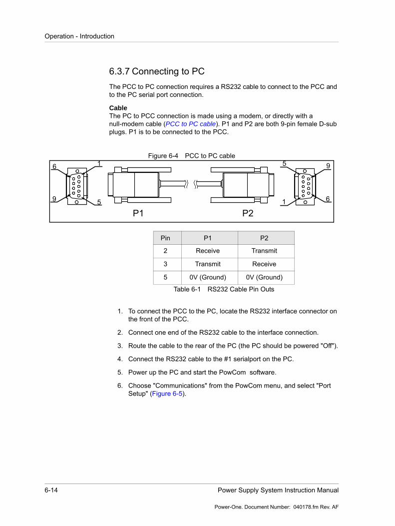
6-14 Power Supply System Instruction Manual
Power-One. Document Number: 040178.fm Rev. AF
Operation - Introduction
6.3.7 Connecting to PC The PCC to PC connection requires a RS232 cable to connect to the PCC and to the PC serial port connection.
CableThe PC to PCC connection is made using a modem, or directly with a null-modem cable (PCC to PC cable). P1 and P2 are both 9-pin female D-sub plugs. P1 is to be connected to the PCC.
Figure 6-4 PCC to PC cable
1. To connect the PCC to the PC, locate the RS232 interface connector on the front of the PCC.
2. Connect one end of the RS232 cable to the interface connection.
3. Route the cable to the rear of the PC (the PC should be powered "Off").
4. Connect the RS232 cable to the #1 serialport on the PC.
5. Power up the PC and start the PowCom software.
6. Choose "Communications" from the PowCom menu, and select "Port Setup" (Figure 6-5).
1
5
6
9 1
5
6
9
P1 P2
Pin P1 P2
2 Receive Transmit
3 Transmit Receive
5 0V (Ground) 0V (Ground)
Table 6-1 RS232 Cable Pin Outs
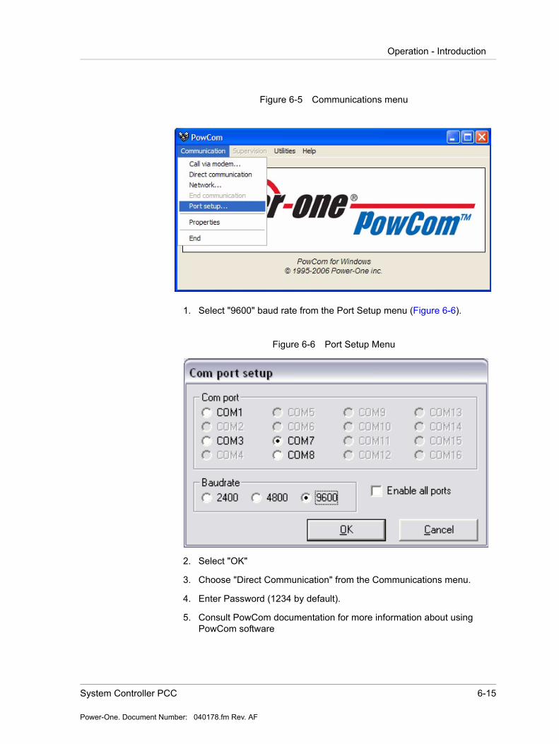
System Controller PCC 6-15
Power-One. Document Number: 040178.fm Rev. AF
Operation - Introduction
Figure 6-5 Communications menu
1. Select "9600" baud rate from the Port Setup menu (Figure 6-6).
Figure 6-6 Port Setup Menu
2. Select "OK"
3. Choose "Direct Communication" from the Communications menu.
4. Enter Password (1234 by default).
5. Consult PowCom documentation for more information about using PowCom software

6-16 Power Supply System Instruction Manual
Power-One. Document Number: 040178.fm Rev. AF
Operation - Introduction
6.3.8 Connecting a ModemModem can be connected to the serial port using a standard modem cable. To setup the modem to auto-answer use the init modem command from the Miscellaneous menu (see menu tree). Some modems may require further initiation to be done before it is connected to the PCC. Please refer to the modem manufacturer’s documentation.
To dial up the system using PowCom, please refer to the PowCom user manual delivered with the PowCom software package.
6.3.9 Boost chargingOpen the "Select/Adjust" menu on the PCC.
Boost charging can be activated by three methods:
Manual boost charging - Choose "U2" in the reference menu for activating boost charging. (Return to float charge manually by choosing "U1", or automatically after a pre-set time.)
Periodic boost charging - after a pre-set period boost charge will be automatically activated for a pre-set time. Interval and boost time to be programmed (for example 4 hours every 3rd week).
Automatic boost charging - when during a mains failure the battery voltage falls below LEVEL t1 value, a timer is started. When the mains return, the system will start an automatic boost. This will last a certain time after the battery voltage reach LEVEL t2. This time will be multiplied with a factor, K. LEVEL t1, LEVEL t2 and the factor can all be set.
Figure 6-7 Boost charging
Voltage (V)Level t2
Level t1
U1 (Float Charge)
MainsInterrupt
MainsReturns
t1 t2=K x t1 Time (hour
System Controller PCC 6-17
Power-One. Document Number: 040178.fm Rev. AF
Operation - Introduction
The following values are adjustable for boost charging:
Boost voltage40 - 60 VoltsBoost time 0 - 200 hoursBoost interval3 - 16 weeksBoost factor 1.0 - 16
Boost t1 40 - 60 VoltsBoost t2 40 - 60 VoltsAuto boost enablePassive - Active
Disabling Automatic Boost Charge:Select "Boost parameters" in the "Adjust limits" menu. Push RETURN, up arrow and RETURN / then select disable.
6.3.10Battery testThe following section contains the procedure for testing the batteries in the system.
Battery testing is activated by selecting U3 (in the "Choose reference" menu.)
Once selected the rectifier voltage will decrease to a pre-set value (U3, adjustable).
The battery test will automatically be interrupted and output rectifier voltage will raise to U1 level, if programmed time or end voltage is reached during the test.
The test is considered as accepted if time causes the interruption.
If the battery voltage reaches programmed end voltage, the battery is considered as faulty, and an alarm will be indicated and further automatic testing is interrupted.
Battery tests can also be set to activate automatically 1-6 times a year. In the "Choose Reference" menu, select "Select no. of tests".
Parameter Settings.The parameter settings feature allows for the partial discharge of the batteries (approx. 30-40% of the capacity) in order to test the batteries for errors. The settings should be done according the battery manufacturer requirements, however, the following settings can be used for standard VR lead batteries:
NOTE Most manufactures of sealed lead acid batteries do not recommend boost charging. If this type of battery is used, the boost function should be totally disabled by settings as follows: Boost time = 0; U2= U1
6-18 Power Supply System Instruction Manual
Power-One. Document Number: 040178.fm Rev. AF
Operation - Introduction
U3 = 1,9 V/cellEnd voltage = 1,94V/cellTime = 40% of expected backup time
Parameters to be set/adjusted from the "battery test" menu or PC with PowCom installed.
Battery test voltage:U3 0- 100 VoltsSymmetry limit: 0.0 - 4.0 VoltsTest end voltage: 0-100 VoltsTest duration: 0- 20 hoursTime of test: 0 - 23 (0=midnight)No of test/year: 0 - 4No of batteries: 0 - 12Battery type: 4 blocks, 3 blocks or 2 blocks
Number of batteries must be equal to number of symmetry measurements. If symmetry cables are not in use, number of batteries must be set to 0 (zero).
6.3.11Temperature compensationThe supervisory module can adjust the charging voltage to compensate for temperatures above or below 20oC. T > 20oC lower charging voltage. T < 20oC higher charging voltage. The zero point for temperature compensation can optionally be set to 25oC.
The temperature compensation function can be enabled and disabled and the level of compensation is adjustable.
6.3.12High loadThe "High Load" alarm is activated when the load current exceeds the capacity of the installed modules multiplied by the high load limit. This is an indication that the system requires increased rectifier capacity.
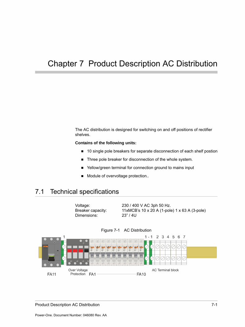
Product Description AC Distribution 7-1
Power-One. Document Number: 046080 Rev. AA
Chapter 7 Product Description AC Distribution
The AC distribution is designed for switching on and off positions of rectifier shelves.
Contains of the following units:
10 single pole breakers for separate disconnection of each shelf postion
Three pole breaker for disconnection of the whole system.
Yellow/green terminal for connection ground to mains input
Module of overvoltage protection..
7.1 Technical specifications
Voltage: 230 / 400 V AC 3ph 50 Hz.Breaker capacity: 11xMCB’s 10 x 20 A (1-pole) 1 x 63 A (3-pole)Dimensions: 23” / 4U
Figure 7-1 AC Distribution
7-2 GDN.C.48.10POS Power Supply System Instruction Manual
Power-One. Document Number: 046080 Rev. AA
Cable cross section output connections
7.2 Cable cross section output connections
Mains connections: Cable area max. 16 mm2
7.3 Installation
This section describes how to connect the mains input wires to the AC distribution.
Unscrew the cabinet's four top fixing screws and slide top-cover forward before lifting it up.
Unscrew the front cover's fixing screws and remove the two front panels according to Figure 4-2 on page 4-4
For correct connection of mains wires see installation drawing in Drawings on page A-1.
Insert the mains cable and connect it to appropriate terminals according marking shown in installation drawing. Make sure the cable is the correct rating (i.e. thick enough) for the selected MCB.
Check, that all the cables are secured tightly to the connectors. Use Torque Table in the Maintenance and troubleshooting chapter for the correct torque.
7.4 Commissioning PBDU
Switch on all MCB's in the AC distribution unit.
Make sure that all rectifier units are ON.
7.5 Maintenance
The AC distribution does not need any special maintenance except for ordinary cleaning.
Maintenance & Troubleshooting 8-1
Power-One. Document Number: 037043.fm Rev. AF
Chapter 8 Maintenance & Troubleshooting
8.1 Installing new Rectifiers
Install new rectifier modules according to following steps:
1. Plug in the rectifier module (installation steps are described in the Installation chapter).
2. Ignore the module alarm caused by current sharing.
3. After 1 minute the yellow LED will start blinking. Wait for maximum 4 minutes.
4. Verify that the yellow LED stops blinking.
5. The alarm should now disappear.
6. Tighten the front screw.
8.2 Troubleshooting
This guide is a step-by-step recommendation of what to do if problems occur. If the first step of the recommendation does not solve the problem continue to the next one. If the problem cannot be solved please call your local Power-One office for assistance.
Low system voltage:
Check the batteries with a voltmeter.
Check the low volt alarm limit in the controller or PowComTM software.
8-2 PPS 10.48-10400 Power Supply System Instruction Manual
Power-One. Document Number: 037043.fm Rev. AF
Troubleshooting
Check that the system is not in battery test mode.
Check the rectifier modules, mains and load situation compared to rectifier capacity.
High system voltage:
Check the batteries with a voltmeter.
Check High volt alarm limit in the controller or using PowComTM software.
Check that the system is not in boost/Charge mode.
Load/battery disconnected:
Verify that the input mains is present.
Check the system DC voltage with voltmeter.
Compare the system DC voltage with disconnected thresholds in the controller or PowCom software.
If a breaker blows repeatedly, there is probably either a load is too high or there is a short circuit at the system.
Mains error:
Check the mains breakers.
Check the mains voltage.
Distribution breaker failure:
Localize the blown breaker.
Check the equipment that is connected to the blown breaker (there may be a reason for this breaker to blow) and reconnect it.
Battery failure:
Check the batteries.
Check the battery test parameters in the controller or using the PowCom software.
Module failure:
Localise the failed rectifier module.
Remove the failed rectifier.
Wait for 30 sec. and reinstall it according to Installing new Rectifiers on page 8-1.
Maintenance & Troubleshooting 8-3
Power-One. Document Number: 037043.fm Rev. AF
Troubleshooting
Battery temp alarm:
Check the batteries.
Check ventilation.
Check the temperature reading in controller or PowComTM interface.
Symmetry fault:
Reset the alarm.
Check the connections according to the number of batteries in the controller or PowCom interface.
Check the batteries.
Battery breaker failure:
Localize the failed breaker.
Check the batteries.
Reconnect the breaker.
High load:
Check load situation according to the capacity of the system.
Increase the number of rectifier modules.
Urgent module failure:
See Module failure.
Communication failure:
Check if there is a rectifier module installed in the current position.
See module failure.
Temp probe failure:
Check the connection of the temperature probe.
Replace the temperature probe.
Alarms are blocked (only with LCD display):
Check the miscellaneous menu in the controller or PowCom interface.
8-4 PPS 10.48-10400 Power Supply System Instruction Manual
Power-One. Document Number: 037043.fm Rev. AF
Maintenance
8.3 Maintenance
The connections on the terminal blocks and circuit breakers must be checked according to the Torque Table below at least once a year.
At least once a year the output voltage should be verified to be within acceptable limits. The result of the test should be recorded and filed to see any deviations.
In addition, the system needs normal cleaning and verification of correct operation. It is very important to keep air inlets and outlets free from dust or other materials, which may prevent free air circulation through the cubical.
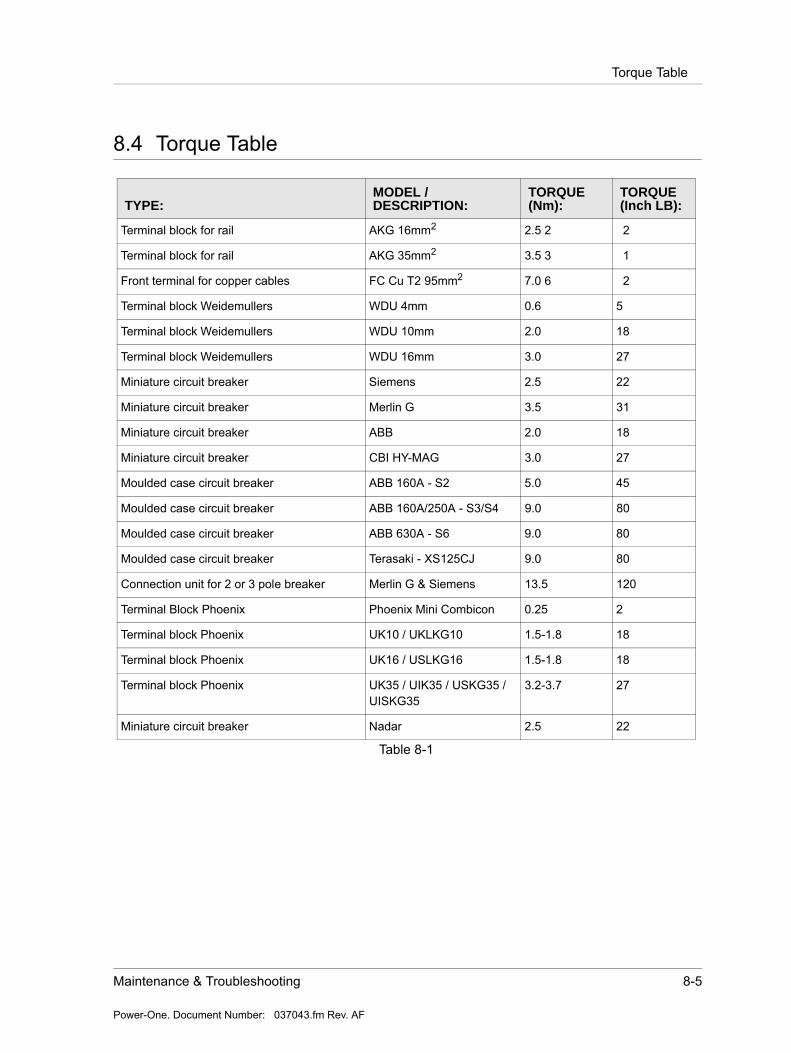
Maintenance & Troubleshooting 8-5
Power-One. Document Number: 037043.fm Rev. AF
Torque Table
8.4 Torque Table
TYPE:MODEL / DESCRIPTION:
TORQUE (Nm):
TORQUE (Inch LB):
Terminal block for rail AKG 16mm2 2.5 2 2
Terminal block for rail AKG 35mm2 3.5 3 1
Front terminal for copper cables FC Cu T2 95mm2 7.0 6 2
Terminal block Weidemullers WDU 4mm 0.6 5
Terminal block Weidemullers WDU 10mm 2.0 18
Terminal block Weidemullers WDU 16mm 3.0 27
Miniature circuit breaker Siemens 2.5 22
Miniature circuit breaker Merlin G 3.5 31
Miniature circuit breaker ABB 2.0 18
Miniature circuit breaker CBI HY-MAG 3.0 27
Moulded case circuit breaker ABB 160A - S2 5.0 45
Moulded case circuit breaker ABB 160A/250A - S3/S4 9.0 80
Moulded case circuit breaker ABB 630A - S6 9.0 80
Moulded case circuit breaker Terasaki - XS125CJ 9.0 80
Connection unit for 2 or 3 pole breaker Merlin G & Siemens 13.5 120
Terminal Block Phoenix Phoenix Mini Combicon 0.25 2
Terminal block Phoenix UK10 / UKLKG10 1.5-1.8 18
Terminal block Phoenix UK16 / USLKG16 1.5-1.8 18
Terminal block Phoenix UK35 / UIK35 / USKG35 / UISKG35
3.2-3.7 27
Miniature circuit breaker Nadar 2.5 22
Table 8-1

8-6 PPS 10.48-10400 Power Supply System Instruction Manual
Power-One. Document Number: 037043.fm Rev. AF
Torque Table

Drawings A-1
Appendix A
Drawings
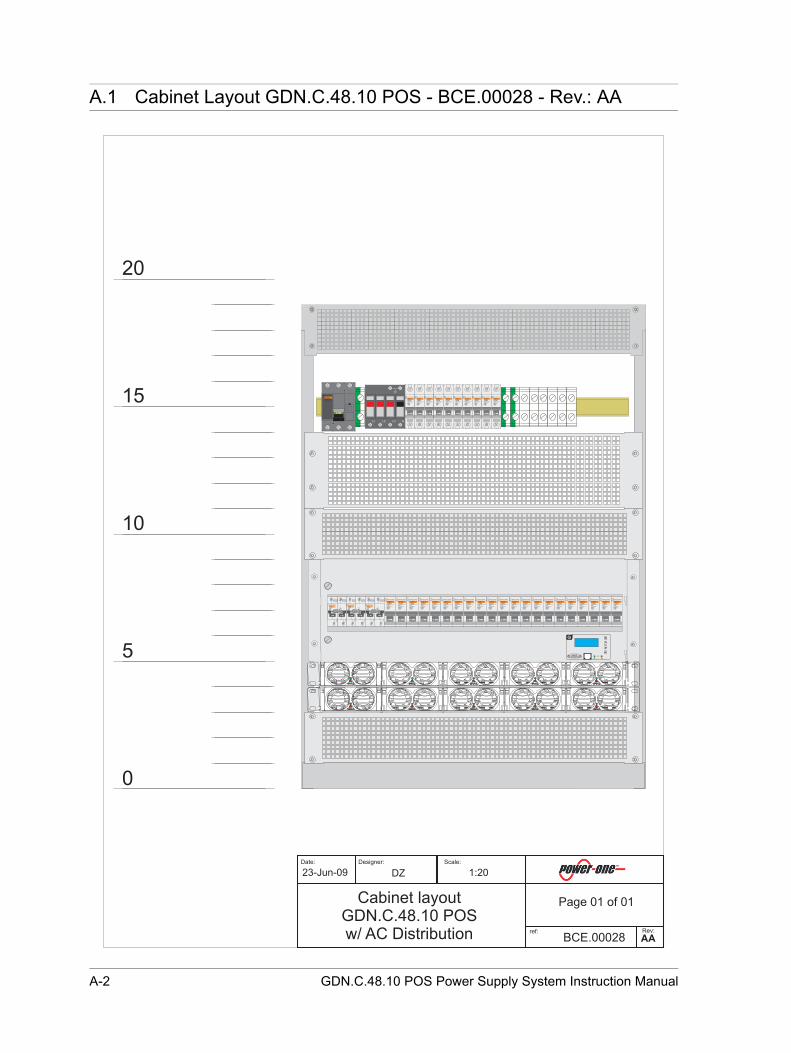
A-2 GDN.C.48.10 POS Power Supply System Instruction Manual
23-Jun-09 DZ 1:20
BCE.00028
Page 01 of 01Cabinet layoutGDN.C.48.10 POSw/ AC Distribution AA
0
5
10
15
20
1
2
3
4
multi 9
C120ND100
MERLIN GERIN
415V
10000
I ONI ON I ONI ON
1
2
3
4
multi 9
C120ND100
MERLIN GERIN
415V
10000
I ONI ON I ONI ON
1
2
3
4
multi 9
C120ND100
MERLIN GERIN
415V
10000
I ONI ON I ONI ON
multi 9
C60NC16230/400V6000
3
MERLIN GERIN
I ONI ON
multi 9
C60NC16230/400V6000
3
MERLIN GERIN
I ONI ON
multi 9
C60NC16230/400V6000
3
MERLIN GERIN
I ONI ON
multi 9
C60NC16230/400V6000
3
MERLIN GERIN
I ONI ON
multi 9
C60NC16230/400V6000
3
MERLIN GERIN
I ONI ON
multi 9
C60NC16230/400V6000
3
MERLIN GERIN
I ONI ON
multi 9
C60NC16230/400V6000
3
MERLIN GERIN
I ONI ON
multi 9
C60NC16230/400V6000
3
MERLIN GERIN
I ONI ON
multi 9
C60NC16230/400V6000
3
MERLIN GERIN
I ONI ON
multi 9
C60NC16230/400V6000
3
MERLIN GERIN
I ONI ON
multi 9
C60NC16230/400V6000
3
MERLIN GERIN
I ONI ON
multi 9
C60NC16230/400V6000
3
MERLIN GERIN
I ONI ON
multi 9
C60NC16230/400V6000
3
MERLIN GERIN
I ONI ON
multi 9
C60NC16230/400V6000
3
MERLIN GERIN
I ONI ON
multi 9
C60NC16230/400V6000
3
MERLIN GERIN
I ONI ON
multi 9
C60NC16230/400V6000
3
MERLIN GERIN
I ONI ON
multi 9
C60NC16230/400V6000
3
MERLIN GERIN
I ONI ON
multi 9
C60NC16230/400V6000
3
MERLIN GERIN
I ONI ON
multi 9
C60NC16230/400V6000
3
MERLIN GERIN
I ONI ON
multi 9
C60NC16230/400V6000
3
MERLIN GERIN
I ONI ON
multi 9
C60NC16230/400V6000
3
MERLIN GERIN
I ONI ON
i
I ONI ON
multi 9
NG125L
MERLIN GERIN
0 OFF0 OFF
L1 L2 L3 N
multi 9
C60NC16230/400V6000
3
MERLIN GERIN
I ONI ON
multi 9
C60NC16230/400V6000
3
MERLIN GERIN
I ONI ON
multi 9
C60NC16230/400V6000
3
MERLIN GERIN
I ONI ON
multi 9
C60NC16230/400V6000
3
MERLIN GERIN
I ONI ON
multi 9
C60NC16230/400V6000
3
MERLIN GERIN
I ONI ON
multi 9
C60NC16230/400V6000
3
MERLIN GERIN
I ONI ON
multi 9
C60NC16230/400V6000
3
MERLIN GERIN
I ONI ON
multi 9
C60NC16230/400V6000
3
MERLIN GERIN
I ONI ON
multi 9
C60NC16230/400V6000
3
MERLIN GERIN
I ONI ON
multi 9
C60NC16230/400V6000
3
MERLIN GERIN
I ONI ON
Date: Designer: Scale:
ref: Rev:
A.1 Cabinet Layout GDN.C.48.10 POS - BCE.00028 - Rev.: AA
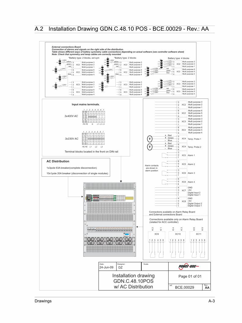
Drawings A-3
24-Jun-09 DZ
BCE.00029
Page 01 of 01Installation drawingGDN.C.48.10POSw/ AC Distribution AA
Terminal blocks located in the front on DIN rail
+
-
Red
Blue
GreenTT
3
2
1
Temp. Probe 1
6
5
4
XC3
XC4
XC6
XC6
3
21
6
5
4
Alarm 3
Alarm 4
Alarm contacts
are shown in
alarm position
XC5
XC5
3
21
6
5
4
Alarm 1
Alarm 2
3
2
1
Multi purpose 6
XC3
Multi purpose 1
Multi purpose 2
Multi purpose 3
Multi purpose 5
Multi purpose 4
6
5
4
XC2
3
2
1
Multi purpose 6
XC2
Multi purpose 1
Multi purpose 2
Multi purpose 3
Multi purpose 5
Multi purpose 4
+
-
Red
Blue
GreenTT
6
5
4
Temp. Probe 2XC4
XC7
4
3
2
GND
1
+5V
Digital Input 2Digital Input 1
XC8
4
3
2
GND
1
+5V
Digital Output 2Digital Output 1
XC9
1 2 3
K2
4 5 6
K1
XC10
1 2 3
K4
4 5 6
K3
XC11
1 2 3
K6
4 5 6
K5
Connections available only on Alarm Relay Board(related for ACC controller)
Connections available on Alarm Relay Boardand External connections Board
-48V
0V
-36V
-24V
-12V(-)12V
(-)24V
(-)36V
Battery type: 4 blocks
-48V
0V
-36V
-24V
-12V
*Battery type: 2 blocks(-)24V
6
5
4
XC2
3
2
1
Multi purpose 6
XC2
Multi purpose 1
Multi purpose 2
Multi purpose 3
Multi purpose 5
Multi purpose 4-48V
0V
-36V
-24V
-12V(-)12V
(-)24V
(-)36V
red
green
blue
6
5
4
XC2
3
2
1
Multi purpose 6
XC2
Multi purpose 1
Multi purpose 2
Multi purpose 3
Multi purpose 5
Multi purpose 4
(-)24V
External connections Board
Table shows different ways of battery symmetry cable connections depending on actual software (see controller software sheet)Note: Check that symmetry and temp cables are correctly mounted
Connection of alarms and signals on the right side of the distribution.
-48V
0V
-36V
-24V
-12V (-)24V
6
5
4
XC3
3
2
1
Multi purpose 6
XC3
Multi purpose 1
Multi purpose 2
Multi purpose 3
Multi purpose 5
Multi purpose 4
-48V
0V
-36V
-24V
-12V(-)12V
(-)24V
(-)36V
6
5
4
XC3
3
2
1
Multi purpose 6
XC3
Multi purpose 1
Multi purpose 2
Multi purpose 3
Multi purpose 5
Multi purpose 4-48V
0V
-36V
-24V
-12V(-)12V
(-)24V
(-)36V
red
green
blue
*Battery type: 2 blocks, ext sym
-48V
0V
-24V
-48V
0V
-36V
-24V
-12V
red
green
yellow
blue
-48V
0V
-36V
-24V
-12V
(-)24V
6
5
4
XC2
3
2
1
Multi purpose 6
XC2
Multi purpose 1
Multi purpose 2
Multi purpose 3
Multi purpose 5
Multi purpose 4
(-)24V
(-)24V
6
5
4
XC3
3
2
1
Multi purpose 6
XC3
Multi purpose 1
Multi purpose 2
Multi purpose 3
Multi purpose 5
Multi purpose 4
red
green
yellow
blue
-48V
0V
-24V
-48V
0V
-24V
-48V
0V
-24V
(-)24V
1
2
3
4
multi 9
C120ND100
MERLIN GERIN
415V
10000
I ONI ON I ONI ON
1
2
3
4
multi 9
C120ND100
MERLIN GERIN
415V
10000
I ONI ON I ONI ON
1
2
3
4
multi 9
C120ND100
MERLIN GERIN
415V
10000
I ONI ON I ONI ON
multi 9
C60NC16230/400V6000
3
MERLIN GERIN
I ONI ON
multi 9
C60NC16230/400V6000
3
MERLIN GERIN
I ONI ON
multi 9
C60NC16230/400V6000
3
MERLIN GERIN
I ONI ON
multi 9
C60NC16230/400V6000
3
MERLIN GERIN
I ONI ON
multi 9
C60NC16230/400V6000
3
MERLIN GERIN
I ONI ON
multi 9
C60NC16230/400V6000
3
MERLIN GERIN
I ONI ON
multi 9
C60NC16230/400V6000
3
MERLIN GERIN
I ONI ON
multi 9
C60NC16230/400V6000
3
MERLIN GERIN
I ONI ON
multi 9
C60NC16230/400V6000
3
MERLIN GERIN
I ONI ON
multi 9
C60NC16230/400V6000
3
MERLIN GERIN
I ONI ON
multi 9
C60NC16230/400V6000
3
MERLIN GERIN
I ONI ON
multi 9
C60NC16230/400V6000
3
MERLIN GERIN
I ONI ON
multi 9
C60NC16230/400V6000
3
MERLIN GERIN
I ONI ON
multi 9
C60NC16230/400V6000
3
MERLIN GERIN
I ONI ON
multi 9
C60NC16230/400V6000
3
MERLIN GERIN
I ONI ON
multi 9
C60NC16230/400V6000
3
MERLIN GERIN
I ONI ON
multi 9
C60NC16230/400V6000
3
MERLIN GERIN
I ONI ON
multi 9
C60NC16230/400V6000
3
MERLIN GERIN
I ONI ON
multi 9
C60NC16230/400V6000
3
MERLIN GERIN
I ONI ON
multi 9
C60NC16230/400V6000
3
MERLIN GERIN
I ONI ON
multi 9
C60NC16230/400V6000
3
MERLIN GERIN
I ONI ON
i
I ONI ON
multi 9
NG125L
MERLIN GERIN
0 OFF0 OFF
L1 L2 L3 N
multi 9
C60NC16230/400V6000
3
MERLIN GERIN
I ONI ON
multi 9
C60NC16230/400V6000
3
MERLIN GERIN
I ONI ON
multi 9
C60NC16230/400V6000
3
MERLIN GERIN
I ONI ON
multi 9
C60NC16230/400V6000
3
MERLIN GERIN
I ONI ON
multi 9
C60NC16230/400V6000
3
MERLIN GERIN
I ONI ON
multi 9
C60NC16230/400V6000
3
MERLIN GERIN
I ONI ON
multi 9
C60NC16230/400V6000
3
MERLIN GERIN
I ONI ON
multi 9
C60NC16230/400V6000
3
MERLIN GERIN
I ONI ON
multi 9
C60NC16230/400V6000
3
MERLIN GERIN
I ONI ON
multi 9
C60NC16230/400V6000
3
MERLIN GERIN
I ONI ON
Input mains terminals.
PE
3x400V AC
76543211
N L1 L2 L3PE
PE
3x230V AC
76543211
L2PE L1 L3
AC Distribution
1x3pole 63A breaker(complete disconnection)
10x1pole 20A breaker (disconnection of single modules)
Date: Designer: Scale:
ref: Rev:
A.2 Installation Drawing GDN.C.48.10 POS - BCE.00029 - Rev.: AA

A-4 GDN.C.48.10 POS Power Supply System Instruction Manual
03.07.2008
Date: Designer:
DZ
Page 1 of 1
Scale:
Powec ref:
044014ref: Rev:
AB
Block diagram GDN.C.48.M24
-- Battery 1- Battery n
0V
- Load 1- Load n
PCC/ACCcontrol unit
PBDUDistribution
Guardian Subrack
LVD
- PLD Load 1- PLD Load n
Optional PLD
See schematic diagram
RS 232 / USB 2.09
J2
8
96
J1
J3
J12 Display10
Ethernet
GDN Shelf 1 5xFMP25
+-
8
8X6 com
X7 com+-
8
8X6 com
X7 com
50 XC1
96
XC1
Internal connections board
1 System voltage2 0V
XC9A Sh1 Dis1
XC9B Sh1 Dis2
XC7 Com.8
XC88
0V 2System voltage 1
System voltage out
RS232
XC250
XC3
XC5 Door alarm
XC6 Surge arrestor alarm
1
1
2
2
6
6
GDN Shelf 2 5xFMP25
See schematic diagramfor Mains connection
321
Alarm
1
654
Alarm
2
321
Alarm
3
654
Alarm
4
XC6 XC5
654
Multi purpose 1-6
XC2
50 XC1
321654
XC3
321
Multi purpose7-12
654321
XC4
Temp1
Temp2
+5V1
+5V2
GN
D
GN
D
4321
XC7
Dig In 1
Dig In 2
+5VG
ND
4321
XC8
Dig O
ut 1D
ig Out 2+5V
GN
DNC2
C3
K6
NO4
NC5
C6
K5
XC11
21
K4
654
K3
XC10
21
K2
654
K1
XC9
NO1 3 3
XC128
RS485
XC138
RS485
Alarm relay board/External connections board
Note:XC9/10/11 available only on
Alarm relay board
A.3 Block Diagram GDN.C.48.10 POS -044014 - Rev.: AB
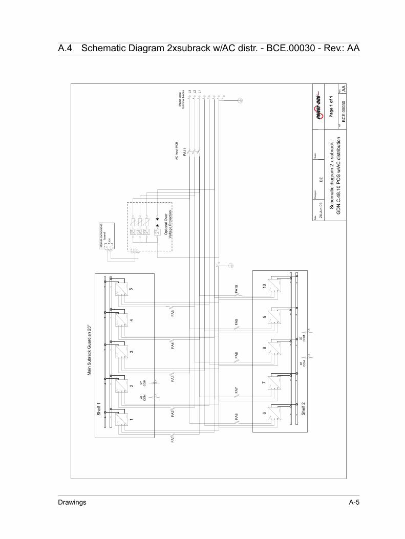
Drawings A-5
24-J
un-0
9
Dat
e:D
esig
ner:
DZ
Page
1 o
f 1
Sca
le:
Pow
ec re
f: BC
E.00
030
ref
:R
ev: AA
Sch
emat
ic d
iagr
am 2
x s
ubra
ck
GD
N.C
.48.
10 P
OS
w/A
C d
istri
butio
n
L N PE
L N PE
L N PE
L N PE
L N PE
88
X6
CO
MX
7C
OM
Mai
n S
ubra
ck G
uard
ian
23'’
123567 4
Mai
ns in
put
term
inal
blo
cks
1
Opt
iona
l Ove
r V
olta
ge P
rote
ctio
n
L N PE
L N PE
L N PE
L N PE
L N PE
88
X6
CO
MX
7C
OM
She
lf 2
She
lf 1
5
67
8
12
34
910
12 11 14
12
XC
6
Inte
rnal
con
nect
ions
bo
ard
1-1
FA1
FA2
FA3
FA4
FA5
FA6
FA7
FA8
FA9
FA10
L3 L2 L1
FA11
AC
Inpu
t MC
B
A.4 Schematic Diagram 2xsubrack w/AC distr. - BCE.00030 - Rev.: AA
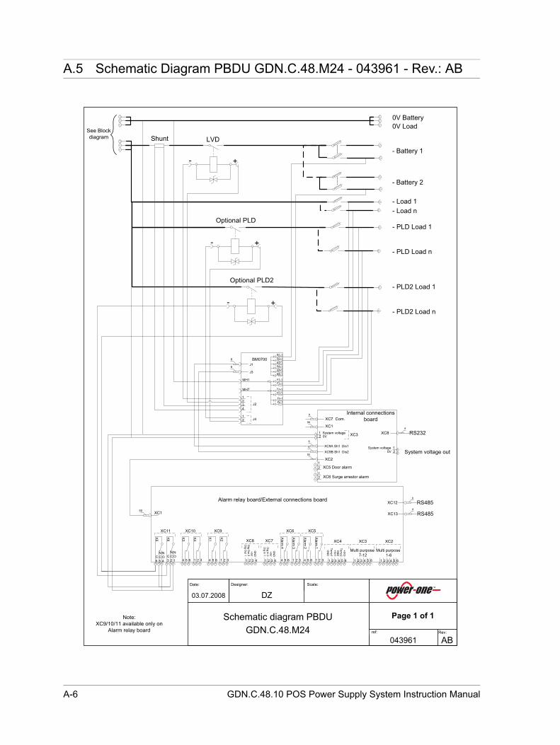
A-6 GDN.C.48.10 POS Power Supply System Instruction Manual
03.07.2008
Date: Designer:
DZ
Page 1 of 1
Scale:
Powec ref:
043961ref: Rev:
AB
Schematic diagram PBDU GDN.C.48.M24
See Block diagram
0V Load0V Battery
- Load 1
- Battery 2
- Load n
- Battery 1
LVD
- PLD Load 1
- PLD Load n
96
XC1
Internal connections board
1 System voltage2 0V
XC9A Sh1 Dis1
XC9B Sh1 Dis2
XC7 Com.8
XC88
0V 2System voltage 1
System voltage out
RS232
XC250
XC3
XC5 Door alarm
XC6 Surge arrestor alarm
1
1
2
2
6
6
321
Alarm
1
654
Alarm
2
321
Alarm
3
654
Alarm
4
XC6 XC5
654
Multi purpose 1-6
XC2
50 XC1
321654
XC3
321
Multi purpose7-12
654321
XC4
Temp1
Temp2
+5V1
+5V2
GN
D
GN
D
4321
XC7
Dig In 1
Dig In 2
+5VG
ND
4321
XC8
Dig O
ut 1D
ig Out 2+5VG
NDN
C2
C3
K6
NO4
NC5
C6
K5
XC11
21
K4
654
K3
XC10
21
K2
654
K1
XC9
NO1 3 3
XC128
RS485
XC138
RS485
- +
Optional PLD
- +
- PLD2 Load 1
- PLD2 Load n- +
Optional PLD2
B1-1B2-1B3-1B4-1B5-1B6-1
F1-1F2-1
Fn-1
6
6J1
J3
J2
J4
MH1
MH7
1234
12
Fn-1
Fn-1Fn-1
Shunt
Alarm relay board/External connections board
Note:XC9/10/11 available only on
Alarm relay board
BM0700
A.5 Schematic Diagram PBDU GDN.C.48.M24 - 043961 - Rev.: AB
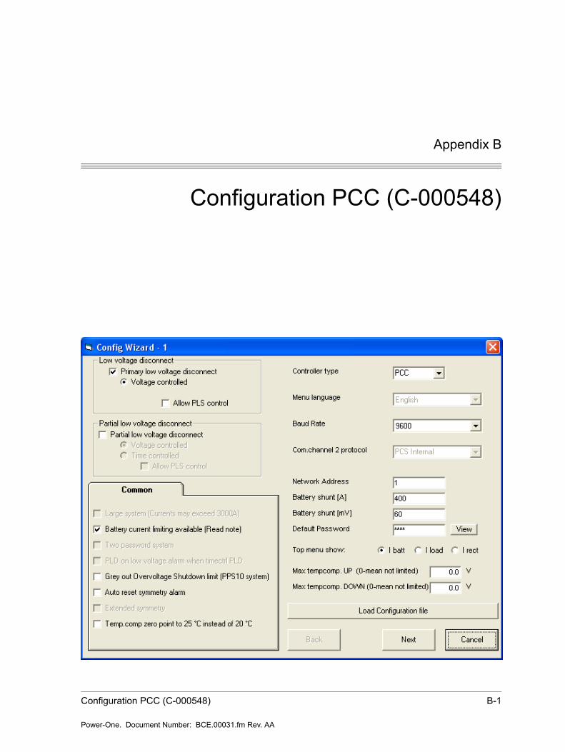
Configuration PCC (C-000548) B-1
Power-One. Document Number: BCE.00031.fm Rev. AA
Appendix B
Configuration PCC (C-000548)
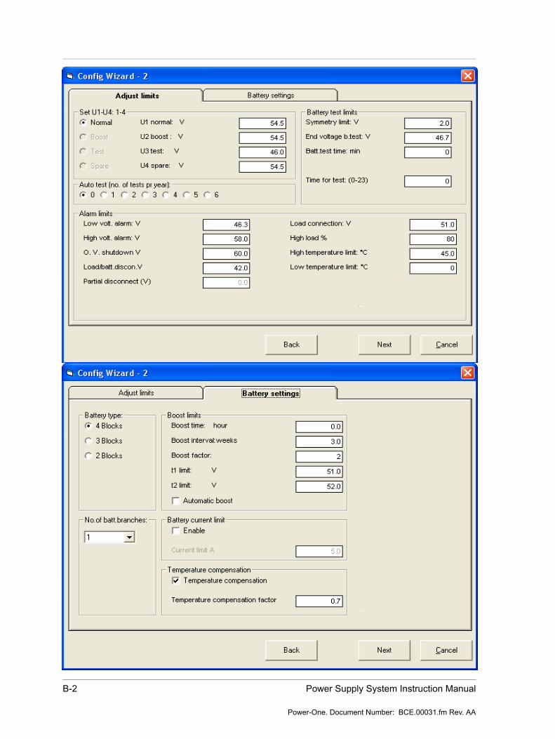
B-2 Power Supply System Instruction Manual
Power-One. Document Number: BCE.00031.fm Rev. AA

Configuration PCC (C-000548) B-3
Power-One. Document Number: BCE.00031.fm Rev. AA
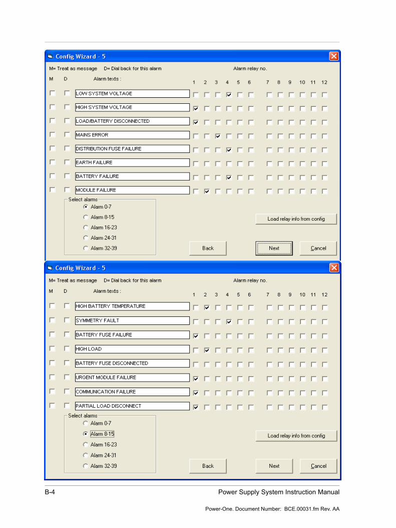
B-4 Power Supply System Instruction Manual
Power-One. Document Number: BCE.00031.fm Rev. AA

Configuration PCC (C-000548) B-5
Power-One. Document Number: BCE.00031.fm Rev. AA

B-6 Power Supply System Instruction Manual
Power-One. Document Number: BCE.00031.fm Rev. AA
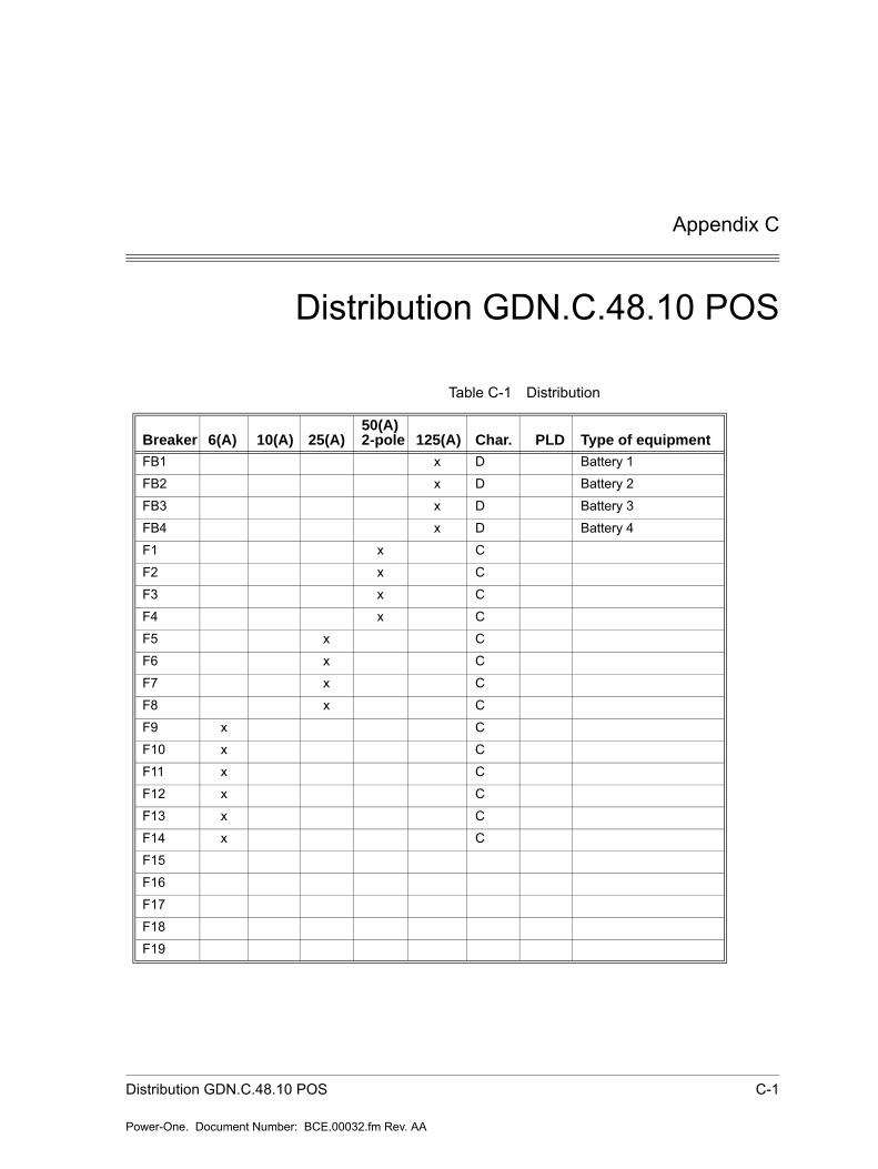
Appendix C
Distribution GDN.C.48.10 POS
Table C-1 Distribution
Breaker 6(A) 10(A) 25(A) 50(A) 2-pole 125(A) Char. PLD Type of equipment
FB1 x D Battery 1
FB2 x D Battery 2
FB3 x D Battery 3
FB4 x D Battery 4
F1 x C
F2 x C
F3 x C
F4 x C
F5 x C
F6 x C
F7 x C
F8 x C
F9 x C
F10 x C
F11 x C
F12 x C
F13 x C
F14 x C
F15
F16
F17
F18
F19
Distribution GDN.C.48.10 POS C-1
Power-One. Document Number: BCE.00032.fm Rev. AA
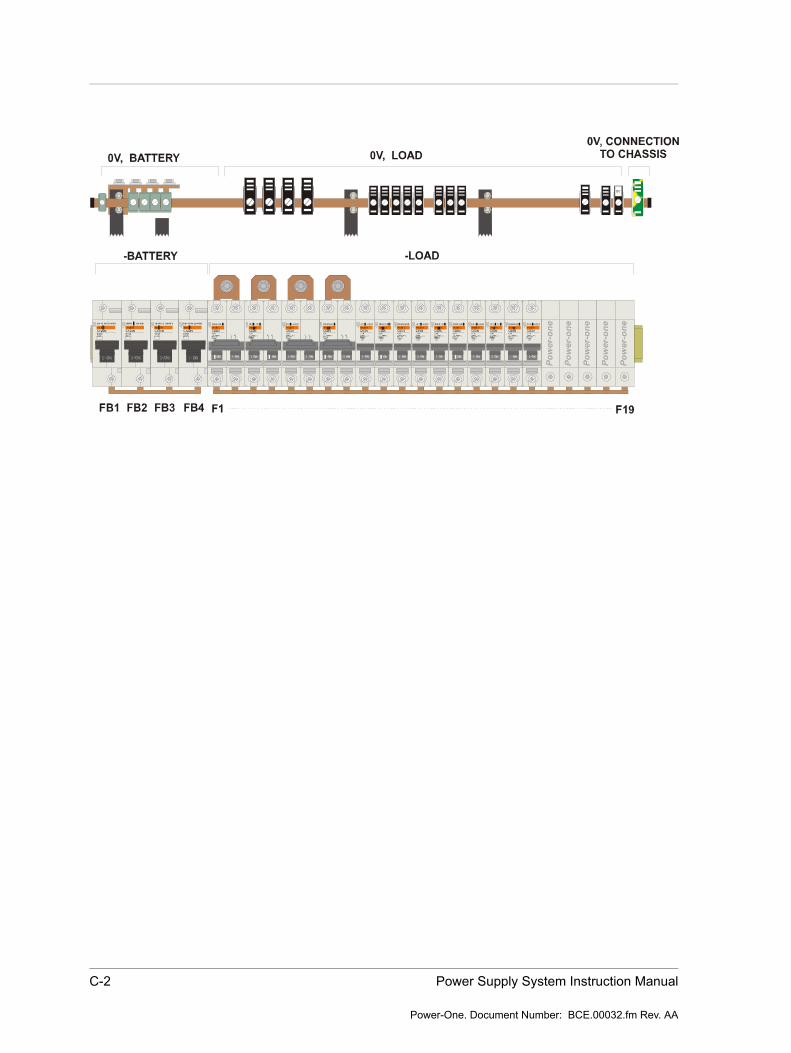
C-2 Power Supply System Instruction Manual
Power-One. Document Number: BCE.00032.fm Rev. AA
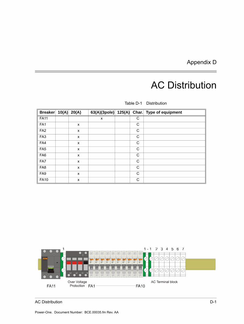
AC Distribution D-1
Power-One. Document Number: BCE.00035.fm Rev. AA
Appendix D
AC DistributionTable D-1 Distribution
Breaker 10(A) 20(A) 63(A)(3pole) 125(A) Char. Type of equipment
FA11 x C
FA1 x C
FA2 x C
FA3 x C
FA4 x C
FA5 x C
FA6 x C
FA7 x C
FA8 x C
FA9 x C
FA10 x C