power generation through speed breaker
TRANSCRIPT


Team Team membersmembersSr
no.
Name Enro. No.
1 Trambadiya vaibhav r. 1216BEME30059
2 Vachhani yagnik k. 1216BEME30061
3 Patel ronak r. 1216BEME30044
4 Patel ronak r. 1216BEME30043

absTraCTIn the present scenario power becomes major need for
human life.
Due to day-to-day increase in population and lessen of the conventional sources, it becomes necessary that we must depend on non-conventional sources for power generation.
While moving, the vehicles posses some kinetic energy and it is being wasted.
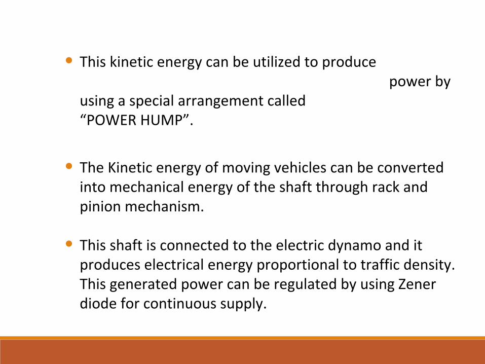
• This kinetic energy can be utilized to produce power by using a special arrangement called “POWER HUMP”.
• The Kinetic energy of moving vehicles can be converted into mechanical energy of the shaft through rack and pinion mechanism.
• This shaft is connected to the electric dynamo and it produces electrical energy proportional to traffic density. This generated power can be regulated by using Zener diode for continuous supply.
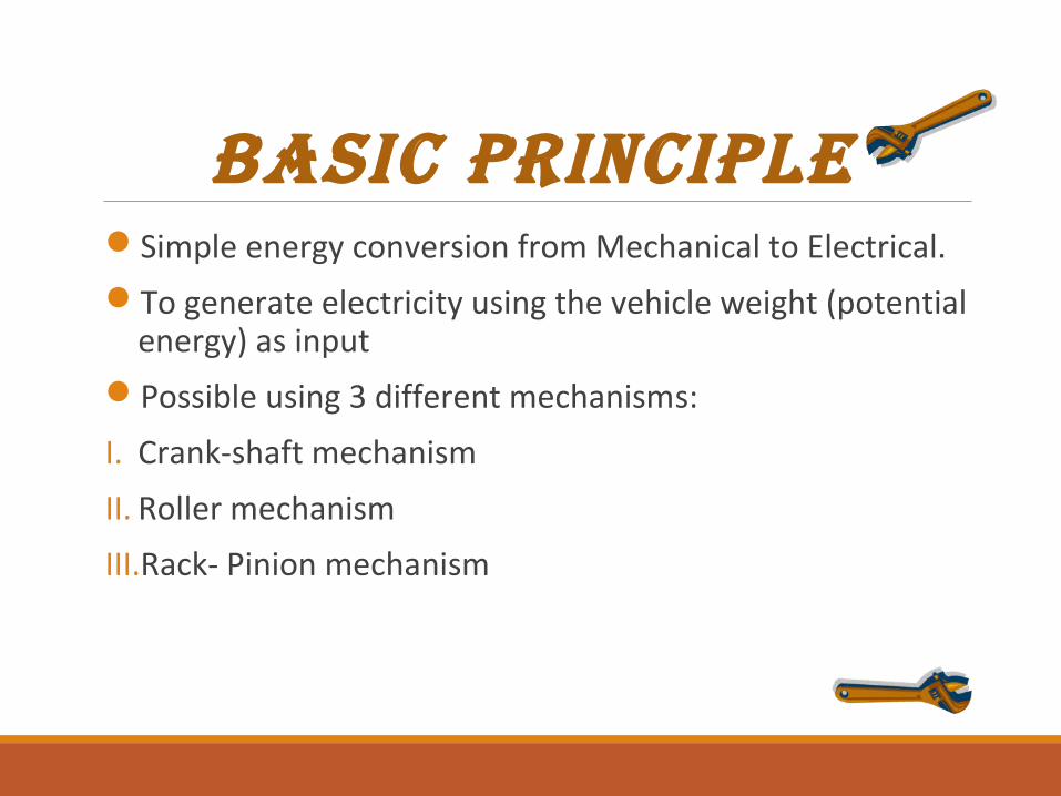
basIC PrINCIPLeSimple energy conversion from Mechanical to Electrical.
To generate electricity using the vehicle weight (potential energy) as input
Possible using 3 different mechanisms:
I. Crank-shaft mechanism
II. Roller mechanism
III.Rack- Pinion mechanism
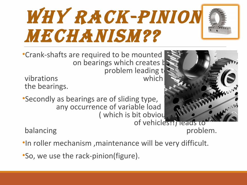
Why Rack-Pinion mechanism??•Crank-shafts are required to be mounted on bearings which creates balancing problem leading to mechanical vibrations which in turn damage the bearings.
•Secondly as bearings are of sliding type, any occurrence of variable load ( which is bit obvious in case of vehicles!!) leads to balancing problem.
•In roller mechanism ,maintenance will be very difficult.
•So, we use the rack-pinion(figure).

Block diagRam
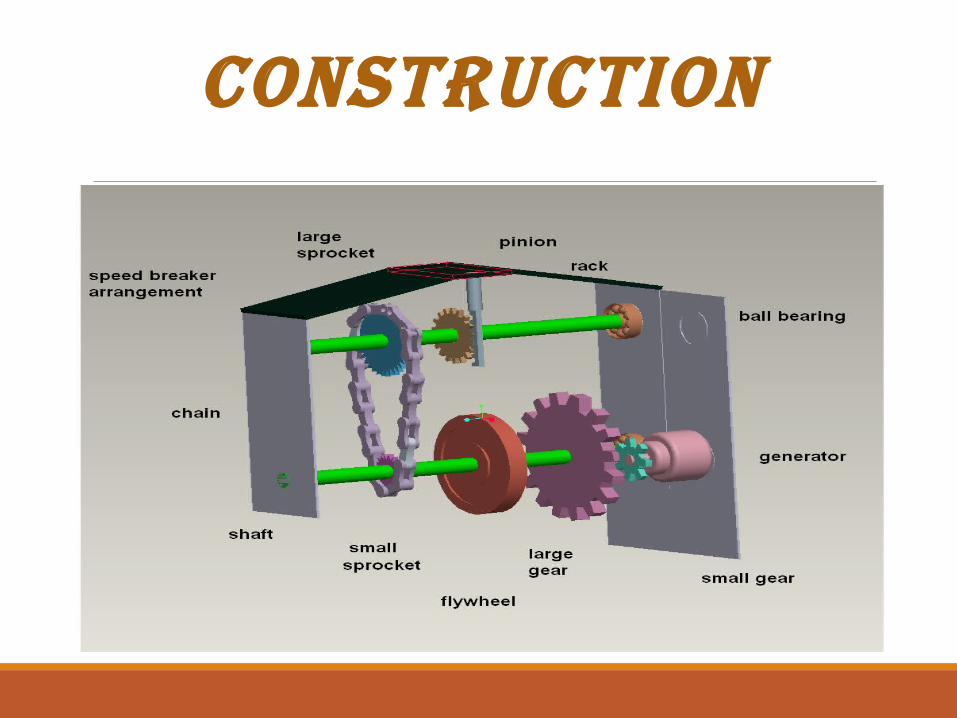
constRuction
WoRking
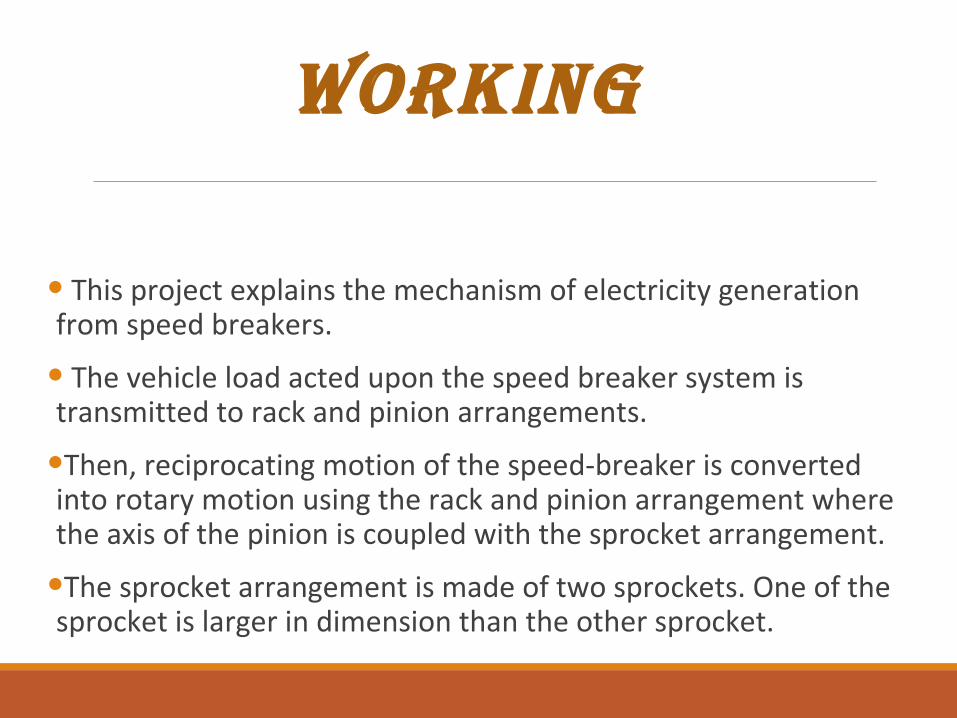
• This project explains the mechanism of electricity generation from speed breakers.
• The vehicle load acted upon the speed breaker system is transmitted to rack and pinion arrangements.
•Then, reciprocating motion of the speed-breaker is converted into rotary motion using the rack and pinion arrangement where the axis of the pinion is coupled with the sprocket arrangement.
•The sprocket arrangement is made of two sprockets. One of the sprocket is larger in dimension than the other sprocket.
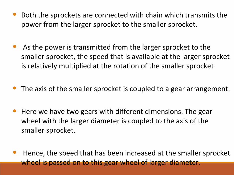
• Both the sprockets are connected with chain which transmits the power from the larger sprocket to the smaller sprocket.
• As the power is transmitted from the larger sprocket to the smaller sprocket, the speed that is available at the larger sprocket is relatively multiplied at the rotation of the smaller sprocket
• The axis of the smaller sprocket is coupled to a gear arrangement.
• Here we have two gears with different dimensions. The gear wheel with the larger diameter is coupled to the axis of the smaller sprocket.
• Hence, the speed that has been increased at the smaller sprocket wheel is passed on to this gear wheel of larger diameter.
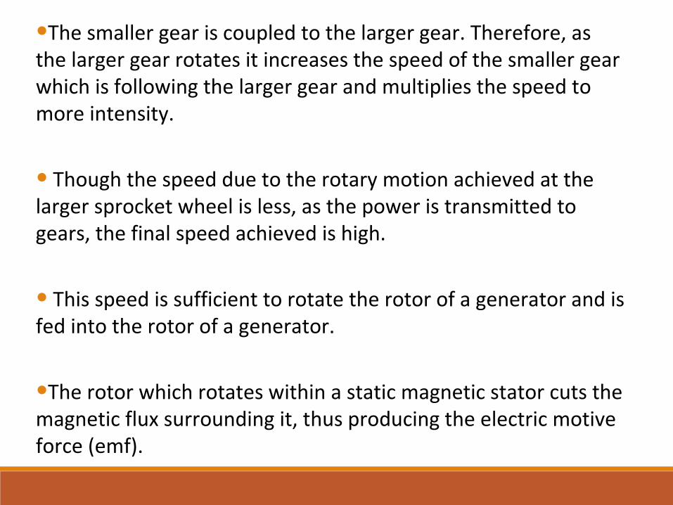
•The smaller gear is coupled to the larger gear. Therefore, as the larger gear rotates it increases the speed of the smaller gear which is following the larger gear and multiplies the speed to more intensity.
• Though the speed due to the rotary motion achieved at the larger sprocket wheel is less, as the power is transmitted to gears, the final speed achieved is high.
• This speed is sufficient to rotate the rotor of a generator and is fed into the rotor of a generator.
•The rotor which rotates within a static magnetic stator cuts the magnetic flux surrounding it, thus producing the electric motive force (emf).

POWER CALCULATIONS• The mass of any vehicle travelling over the speed
breaker= 300Kg (Approximately) • Height of speed brake = 15 cm = 0.15 m• Work done = weight of the body x distance travelled by
the vehicle • Here, Weight of the Body = 300 Kg x 9.81 = 2943 N• Distance traveled by the body = Height of the speed
breaker = 15cm • Power = Work done/Second = (2943 x 0.15)/60 = 7.3575
Watts Output
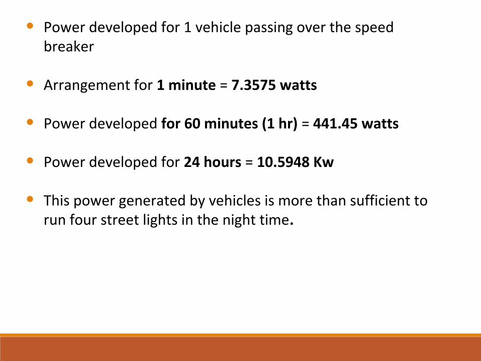
• Power developed for 1 vehicle passing over the speed breaker
• Arrangement for 1 minute = 7.3575 watts
• Power developed for 60 minutes (1 hr) = 441.45 watts
• Power developed for 24 hours = 10.5948 Kw
• This power generated by vehicles is more than sufficient to run four street lights in the night time.

ADVANTAGES
• The project is easy to install.
• The project is eco-friendly.
• Maintenance and installation cost are low.
• Pollution free power generation. • Less floor area required.
• No need of manpower during power generation.
•Don’t want to see India as an energy deficient country.
•It should be of least cost, as well as of less weight.
•Efficiency should be as high as possible.
•Losses should be minimum.
OUR GOALS
Future scope
•The shortage of light can be reduced at some extant.
•Wastage of energy can be minimized.
•Flywheel can be used to increase the rotational speed of the Dynamo shaft.
•It may also be used for light vehicle.

• It is an non conventional type of producing the energy.
• Existing source of energy may not be adequate to meet the ever increasing demands, So this project is a one step to path off that way.
• This project will be helpful to solve some of the Electricity shortage problems.
conclusion
reFerence
•Multidisciplinary journal of research in engineering and technology volume 1,issue 2 page 202-206 www.mjret.in/
•Electricity generated by Agrawal.
•www.theijes.com/papers/
•International journal of advance in engineering and technology www.e-ijaet.org/
•International journal of innovations in engineering and technology www.ijiet.com/
•G.D RaiNon conventional energy sources.

thank you