power electronics reversing thyristor controllers for...
TRANSCRIPT

Power Electronics
Reversing Thyristor Controllers
for Servo Drives
TS 700E, TS 700K, TS 701 ... TS 715

All details in this brochure are applicable at the time of issue. The contents may be subject to modification for the purpose of technicalimprovement. The regulations applicable to installation and commissioning must be observed. Circuits and project design notes given aresuggestions only and therefore no warranty can be accepted.
Attention:Instructions highlighted by this heading must be strictly observed in order to prevent hazardous situations that might endanger human life.

Reversing Thyristor Controllers 3
Contents Page
Reversing Thyristor Controllers for Electrical Servo Drives 4Application 4Summary of the Principal Features 4
Reversing Thyristor Controller TS 700E 5Application 5Mechanical Design 5Principle of Operation 5Technical Characteristics 6Block Diagram 8Dimension Drawing 9
Reversing Thyristor Controller TS 700K 10Application 10Mechanical Design 10Principle of Operation 10Technical Characteristics 11Block Diagram 13Dimension Drawing 14
Reversing Thyristor Controller TS 701, TS 705 15Application 15Mechanical Design 15Principle of Operation 15Technical Characteristics 16Block Diagram 19Dimension Drawings 20
Reversing Thyristor Controller TS 711, TS 715 21Application 21Mechanical Design 21Principle of Operation 21Technical Characteristics 22Block Diagram 25Dimension Drawings 26
Table of Contents

4 Reversing Thyristor Controllers
Application
Today's industrial production plants rely more and more onelectronic devices for logic and closed-loop control.
In many fields, optimization of process controls is achieved bycontrolling the material flow with the aid of electromotive actuatorsdriven by three-phase asynchronous or single-phase capacitormotors.
Electronic reversing thyristor controllers are often used in suchapplications. They offer many advantages over conventional rever-sing mechanisms such as contactor reversers or thyristor reverserswith reversing switches. The electronic devices are free of wearand tear, need no maintenance and impress by their long-evity andhigh number of operations.
Power reversing controllers change the motor´s sense of rotationby converting the signals of the electronic variable speed systemsfrom 24VDC to 230 or 400VDC.
In addition to their principal task of reversing the motor direction,thyristor controllers also provide facilities such as:
• contactless electrical braking of the motor at the end of thepulse, therefore free of wear and tear;
• monitoring of the motor temperature by means of PTCthermocouples and output of a signal if critical values areexceeded;
• protection against phase short circuits by means of minimumpause periods during direction change-over;
• phase monitoring;
• interlocked direction commands;
• consideration of torque limits and travel limits in the control pro-cess;
• disabling of direction commands through an external signal
• transmission of information on faults and travel limit signals tothe automation unit on the next higher level.
Summary of the Principal Features
TS 700K TS 700E TS 701 TS 705 TS 711 TS 715
Supply voltage 230VAC 230VAC 400VAC 400VAC 400 VVAC 400 VVAC
Max. motor rating 0.23 kW 0.7 kW 1.5 kW 5.5 kW 1.5 kW 5.5 kW
Evaluation oftravel limit signals X X
Motor braking X X X X
Mechanical design Built-on housing 19" plug-in unit 19" plug-in unit 19" plug-in unit 19" plug-in unit 19" plug-in unit
Motor temperature monitoring X X X X X
Suitable for switchingsingle-phase capacitor motors X X
Suitable for switching three-phase asynchronous motors X X X X
Reversing Thyristor Controllers for Electrical Servo Drives

Reversing thyristor controller TS 700E
ApplicationPreferably used for directional switching of electrical servo driveswith single-phase capacitor motors.
Mechanical DesignThe reversing thyristor controller TS 700E is a plug-in unit intendedfor a 19" cartridge ( 3 HE, 14 TE) for installation in a standardsubrack that has been prepared for this purpose. All indicatingelements are placed on the front of the unit. To access theswitches and potentiometers for setting the control parameters forthe actual application the unit must be pulled out from the rack afterhaving first switched off the mains supply by means of theintegrated safety switch.The electrical connections are made through plug-in connectors.
Principle of OperationThe binary inputs for direction control are interlocked. The directioncommand 'right turn' (RL) or 'left turn' (LL) takes effect after a delayof 20 to 40ms. The motor control signal whose minimum durationcan be preselected in the range from 60 to 200ms in steps of20ms, is available at the output of the thyristor controller (L1 RL orL1 LL). The thyristors are switched at zero crossing.Every direction command is followed by a series of braking pulsesprovided that a braking time has been set. The braking time can beselected by a switch, in steps of 20ms from 0 to 180ms.Delay time, minimum duration of the motor control signal and bra-king period are valid at a mains frequency of 50Hz. Any increase inthe frequency will reduce these periods.The braking time should be kept as short as possible in order toavoid unnecessary heating of the motor. In many cases, brakingcan be dispensed with altogether. This depends on the type ofactuating unit used. Every change of direction is followed by a compulsory pause whichis selectable in the range from 0.25 to 2.5 seconds. The direction commands RL and LL can be made ineffective byapplying the inhibit signal. Limit position signals may be incorporated in the control process.Limit values for both parameters – travel and torque – can bedetected and evaluated.
The travel limit switches are triggered either at zero current (nor-mally closed contact opens at limit position) or at working current(normally open contact closes at limit position). The selection ismade by bridging pins b32 and z32 of plug connector X1. The limitswitch for torque monitoring, however, always operates at NCcurrent. The thyristor controller is activated as soon as the limit position isreached. It keeps driving the motor in the direction of the limitposition until finally the torque limit switch operates. However, theslowing-down time selected is never exceeded. To ensure that the torque limit point is reached, the slowing-downperiod must exceed the drive's running period from travel limit pointto torque limit point. The motor is switched off upon arrival at torquelimit and electric braking is started. The direction signal towards thelimit position is inhibited at the same time. The motor is made toleave the limit position by applying the signal for the reversedirection. To ensure maximum torque at the point of reversal(start-up torque) any signal 'torque limit position reached' that mightoccur at this instant is ignored. The torque limit signal remainsinhibited until finally the travel limit switch becomes inactive again,but in any case not longer than the slowing-down time defined. Theslowing-down time for the limit position in the left direction may beset to zero by bridging pins b32 and d32 of connector X1.The positions of the travel limit switches on the drive trigger onerelay each. The floating change-over contact of this relay may beused for plant control purposes. A floating (change-over) contact isavailable for external fault indication. The following conditions generate an alarm indication after a delayof 3 seconds approximately:• Excessive temperature inside the device• Both travel limit switches triggered simultaneously• Torque limit position signalled although the corresponding travel
limit position is inactive• Slowing-down time after reversal from torque limit position
expired while the travel limit switch is still in the ON state• Thyristor breakdown • Voltage failure• Safety switch tripped • Failure of internal voltage supply • External inhibit signal applied
The fault signal is also available in the form of a pulse of about0.5 seconds, provided that the internal control voltage is stillpresent. This may be used to generate a static/dynamic groupalarm. Protective motor switches alone do usually not provide sufficientmotor protection. PTC thermocouples inside the motor winding arebetter suited for this task. An appropriate evaluation circuit isintegrated in the TS 700E device. A floating change-over contactsignals the response of the thermocouples. However, the motor isnot switched off directly by these contacts.The inputs for the direction commands (LL, RL), the inhibit signal(SP) and the position of the limit switches are galvanically isolatedfrom the internal circuits.An internal control voltage of 24VDC supplies the inputs. Alternati-vely, the control voltage may be obtained from an external source.The reference potential must in any case be taken from the voltagesource used. Any link between the external and internal controlvoltages should be avoided. Additional resistors (3.3 kOhms each,integrated in the device) may be shunted with the inputs LL, RLand SP in order to attenuate line disturbances. This is done bysetting the jumpers of connector X1 accordingly. All the important operational states are displayed by LED indicatorsat the front of the device.
Reversing Thyristor Controllers 5
Reversing Thyristor Controller TS 700E

Power StageSupply voltage 230VAC, +10%, - 20%(can be disabled throughintegrated safety switch)
Frequency 50Hz to 60Hz
Rated current 3A
Start-up current 12A max.
Motor rating 10W to 700W
Max. switching frequency 2400 switching operations /h
Operating mode For actuating drives in DINVDE 0530 intermittent operation,
duty cycle S5 - 10%
BrakingAfter every actuating command; determined by an adjustablenumber of DC half-waves; may be disabled.
Series connected protection According to motor rating
Internal protection Safety switch with remoteindication, FSA 231: 1.1 to 3A, 230V
Actuating ModeRight or left rotation, pulse-driven, with synchronization at zerocrossing.
Control StageInput signals +24VDC, galvanically isolated LL, RL, SP from the local control voltage.Input voltages basic isolated acc. to DINVDE0160.1 signal +15V to +30 V 0 signal -15V to +5VCurrent consumption 2mA max. at 24VDC Delay 20ms to 40ms The input resistance of the control inputs LL, RL, SP may be redu-ced to 3.3 kOhms by setting some links at the X1 connector if thisproves necessary in order to attenuate interfering signals on thecontrol lines to the thyristor controller. In this case, the maximumcurrent consumption per input increases to 10mA at 24VDC
Input for Floating contact betweentravel limit signals input and auxiliary voltage UH+ per input for: Travel limit, left (WEL)
Travel limit, right (WER)Torque limit, left (DEL)Torque limit, right (DER)
The torque limit switches must only be active at rest current, i.e. the normally closed contact opens as soon as the limit position isreached.
1 signal Contact is open0 signal Contact is closed
The travel limit switches may also operate with NO contacts, i.e.the contact is closed as soon as the travel limit is reached. 1 signal Contact is closed0 signal Contact is openThe choice between NO and NC contact is made by setting the linkz32 - b32 in the X1 plug connector.Link inserted NC contactLink not inserted NO contact
Minimum command period 40ms
Auxiliary voltage UH +24VDC, galvanically isolated
Load 46mA max., short-circuit proof
MonitoringInhibited Upon failure of internalactuating commands supply voltage
Interruption of power supply Upon excessive temperaturefor electronics inside the device
Integrated safety switch Upon thyristor breakdownis tripped
Fault indication Upon overtemperature ofmotor winding
Operating Mode Indicationthrough LEDs at the front plateB (green) Ready for operationRL (yellow) Actuating command, RightLL (yellow) Actuating command, LeftSP (yellow) External inhibit signal ONBR (yellow) Braking period in progressSTG (red) Fault inside the deviceSTW (red) Overtemperature of motor
windingSTE (red Fault at limit positionWER (yellow) Right travel limit reachedDER (yellow) Right torque limit reachedWEL (yellow) Left travel limit reachedDEL (yellow) Left torque limit reached
Adjustable Control ParametersThe adjustable controls can only be accessed if the module isremoved from the rack. Switch off the power supply of the devicebefore changing the settings!
Minimum actuating period at 60ms to 200ms, in steps of 20mspower output tsm (at 50Hz mains frequency)Factory setting 200ms
Braking period tbr 0ms to 180ms, in steps of 20ms (at 50Hz mains frequency)
Factory setting 0msMinimum pause period tP 0.25s to 2.5s progressively between RL and LL adjustableFactory setting 0.25s
Technical Characteristics TS 700E
6 Reversing Thyristor Controllers

Slowing-down period at 40ms to 1.5s progressivelytravel limit position tnz adjustableFactory setting 40ms
Motor TemperatureEvaluation amplifier for 1 to 6 PTC thermocouples according toDIN 44 081, floating input.
Attention:In a fault situation it might happen that this circuit reaches thepotential of the power circuit.
Total cold resistance of the monitoring loop 1.5kΩ typicallyThreshold value 2.5kΩ to 3.6kΩFall value 1.5kΩ to 2.3kΩ
Fault IndicationFault, static 1 change-over contacts, floating,
60VDC, 25VAC, 1A max.(zero current operation)
Fault, dynamic 1 change-over contact, floating, 0.5s approx. 60VDC, 25VAC, 1A max.
(working current operation)
Motor temperature 1 change-over contact, floating, 60VDC, 25VAC, 1A max.(working current operation)
Travel limit position, Right 1 change-over contact, floating, 60VDC, 25VAC, 1A max.(zero current operation)
Travel limit position, Left 1 change-over contact, floating, 60VDC, 25VAC, 1A max.(zero current operation)
Voltages must be basic isolated acc. to DINVDE0160.
Electrical ConnectionsPower input and output Plug connector Motor monitoring H-design (15 pin),
pre-mating contact forearth conductor, DIN 41 612
Signals Plug connector,F-design 48 pins, DIN 41 612
Test voltagesSurge voltage testPower stage / ground 2.5kV, 1sControl stage / ground 1.0kV, 1sPower stage /control stage 2.5kV, 1sAll interfaces respectively control input or output, must be coveredto an additional insulation. Do not activate the device only with acurrent-operated protective device.
Operating ConditionsMounting position Horizontal, front plate
facing to the frontPermissible ambient temperatureoperation 0 °C to +55°Ctransport and storage -25°C to +70°C
Humidity 90% relative humidity max.at 30 °C
Mechanical StrengthOscillates 2 g, ±0.15 mm, 10Hz to 150 HzDIN IEC 68-2-6 3x20 cycles, 1 octave /min
Bump 15g, /6ms/3x4000 shocksDIN IEC 68 - 2 - 29
Power loss ≤10W at 230V and 3A load current
Standards / RegulationsRated insulation voltagesDIN VDE 0160Power stage 230VACControl stage 60VDCFault signalling output 60VDC, 25VAC
Isolation between power and control stages DIN VDE 0160
Creepage distances and Pollution degree 2clearances DIN VDE 0110 Overvoltage class III
Insulation Insulation class IDIN VDE 0100, section 410
Protection class IP 40 at the front panel, whenDIN 40 050 mounted in rack
IP 00 at connections
Interference immunity Intensity of test 3 for mains, DIN VDE 0843, sections 2 and 4 motor and control connections
HousingPlug-in type 3 HE, 14 TE acc. to DIN 41 494
section 5
DimensionsFront plate 70.78mm x 128.4mm
Mounting depth 193.5mm (without handle) Protrusion of handle: 15mm max.
Weight 1kg approx.
Ordering Details
Designation Order Reference
Reversing thyristor controllerTS 700E 31 - 99 - 101
Reversing Thyristor Controllers 7
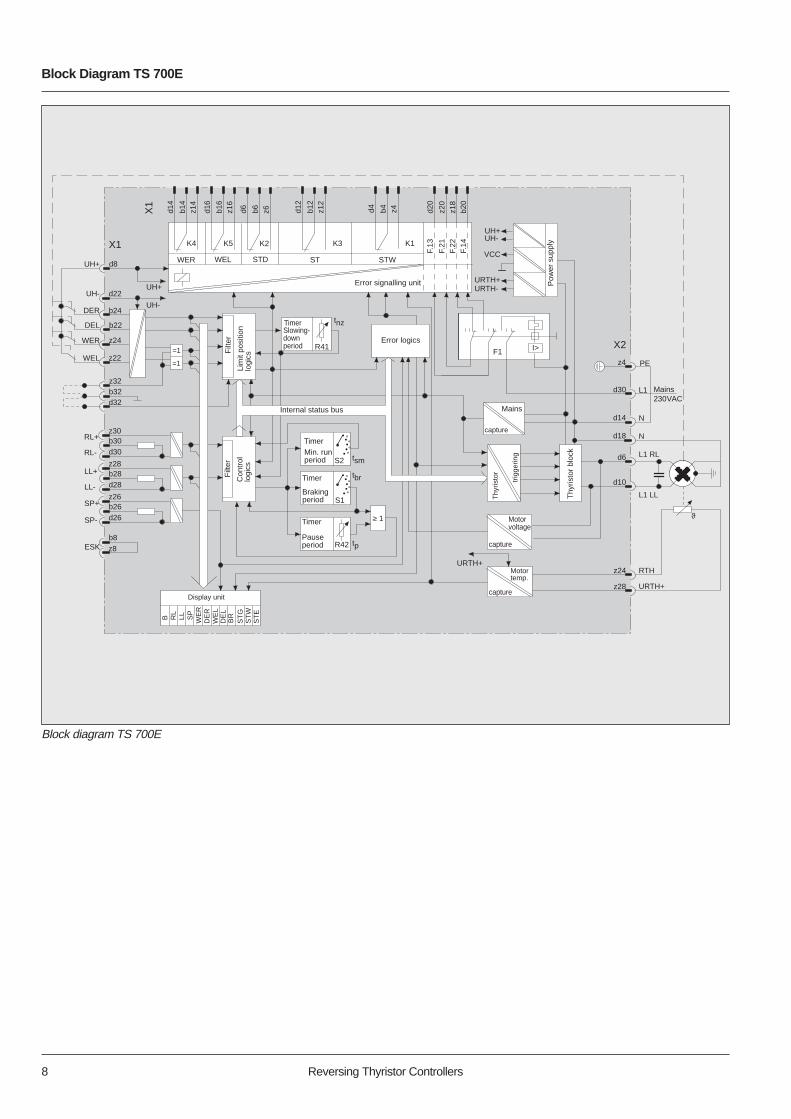
Block Diagram TS 700E
8 Reversing Thyristor Controllers
DEL
WEL
Filt
er
Lim
it po
sitio
n lo
gics
Filt
er
Con
trol
lo
gics
UH+
UH-
Error logics
TimerSlowing-down period R41
tnz
Internal status bus
TimerMin. runperiod
Timer
Brakingperiod
Timer
Pauseperiod
≥ 1
tsm
tbr
tp
F1 I>
VCC
Thy
risto
r bl
ock
Mains
capture
Thy
risto
r
trig
gerin
g
L1 Mains230 V AC
L1 LL
L1 RL
N
d8
b22
z22
d6
d10
d14
d30
RL+
RL-S2
=1
=1
DER
WER
LL-
LL+
SP+
SP-
ESK
B
Display unit
RL
LL SP
WE
RD
ER
WE
LD
EL
BR
ST
E
ST
GS
TW
R42
• • • • •
• • • • •
S1
UH+UH-
URTH+URTH-
K4 K5 K2 K3 K1
WER WEL STD ST STW
Error signalling unit
z6b6d6z16
b16
d16
z14
b14
d14
PEz4
X2
URTH+
Motorvoltage
capture
N
ϑ
z24
z28
RTH
URTH+
Motortemp.
capture
z8b8
d26b26z26
d28b28z28
d30b30z30
d32b32z32
z24
b24
d22UH-
UH+
X1
X1
F.14
F.22
F.21
F.13
b20
z18
z20
d20
Pow
er s
uppl
y
z12
b12
d12
z4b4d4
d18
Block diagram TS 700E

Dimension Diagram TS 700E
Reversing Thyristor Controllers 9
Dimension Diagram TS 700E
TS
700
E F
128.4
68.92
32.5
25
111
142.
51.
5
167
X1
X2
B RL
LL SP
BR
ST
G
ST
W
ST
E
WE
R
DE
R
WE
L
DE
L
tsm
tp
tnz
tbr

Reversing thyristor controller TS 700K
Application
Preferably used for directional switching of electrical servo driveswith single-phase capacitor motors.
Mechanical Design
The reversing thyristor controller TS 700K is intended for mountingon standard rails according to DIN EN 50022-35. All indicatingelements and the setting potentiometers for the minimum actuatingtime, the braking time and the slowing-down time at limit positionCLOSED are at the front of the device.
The lever of the integrated safety switch allows single-pole (phase)disconnection from the mains. The electrical connections are madethrough screw-type connectors.
Principle of Operation
The binary inputs for direction control are interlocked. The directioncommand OPEN (A) or CLOSED (Z) takes effect after a delay of20ms to 40ms. The motor control signal whose minimum durationcan be preselected in the range of 80ms to 400ms, is available atthe corresponding actuator output L1 A or L1 Z. The thyristors areswitched at zero crossing.
Every direction command is followed by a series of braking pulsesprovided that a braking time has been set. The braking time isselectable from 0ms to 200ms.
The braking time should be kept as short as possible in order toavoid unnecessary heating of the motor. In many cases, brakingcan be dispensed with altogether. This depends on the type ofactuating unit used.
Every change of direction is followed by a compulsory pause ofmore than 100ms.
This compulsory pause will have the same length as the brakingtime if the latter was set to more than 100ms.
Limit position signals may be incorporated in the control process.The thyristor controller provides a 24VDC auxiliary voltage for thispurpose which is connected to the binary inputs (EA, EZ) throughthe limit switches.
Triggering of the limit switches must always occur at rest current(normally closed contact opens on arrival at limit position).
When the limit position CLOSED is reached the drive continues forthe period of the slowing-down time defined. Then, electricalbraking sets in and the direction signal CLOSED is inhibited. Withthe end position OPEN, there is no slowing-down phase of themotor.
It is possible to leave a limit position again by giving the commandfor moving in the opposite direction.
If the drive is in the limit position CLOSED then issuing thecommand OPEN initiates a monitoring function. The drive mustnow leave the position CLOSED within a certain delay, the lengthof which is identical to the length of the slowing-down timeselected. Otherwise a fault message would be displayed; the drivewould however not be switched off.
The TS 700K reversing thyristor controller comes in two differentversions, depending on the type of direction inputs A and Z (voltageinput or floating contact). All inputs are galvanically isolated fromthe internal circuit voltage. In the device offering a voltage input,there is an additional galvanical isolation between the inputs for thedirection commands (EA and EZ) and the limit signals.
A floating contact (NC, zero current operated) is available forexternal fault indication.
The following conditions generate an alarm indication after a delayof 3 seconds approximately:
• Excessive heat inside the device
• Both travel limit switches triggered simultaneously
• Slowing-down time expired, but drive has not left the limitposition CLOSED
• Thyristor breakdown
• Voltage failure
• Safety switch tripped
• Failure of internal voltage supply
A useful accessory for these modules is our newly developed andpatent registered wire clamp which helps to keep order inside thecontrol cubicle. The comb-type clamps are made of self-extinguishing synthetics and are self-adhesive. They can easily beplaced where necessary (see dimension drawing). Please state the number of wire clamps required when placing yourorder.
Reversing Thyristor Controller TS 700K
10 Reversing Thyristor Controllers

Power StageSupply voltage 230VAC ,+10 %, - 20 %(can be disabled throughintegrated safety switch)
Frequency 50Hz to 60Hz
Rated current 1A
Start-up current 4A max.
Motor rating 10W to 230W
Max. switching frequency 2400 switching operations / h
Operating mode For actuating drives in DIN VDE 0530 intermittent operation,
duty cycle S5 - 10 %
BrakingAfter every actuating command; determined by an adjustablenumber of DC half-waves; may be disabled.
Series connected protection According to motor rating
Internal protection Safety switch with remoteindication, FSA 231: 1.1 to 1A, 230V
Actuating ModeDirectional motor control (OPEN or CLOSE), pulse-driven, withsynchronization at zero crossing.
Control StageInputs for sense of rotation OPEN (A) or CLOSE (Z).
Version "Voltage input": +24VDC input, isolated from local control voltage and from limit inputs. Input voltages basic isolated acc. toDINVDE0160.1 signal +15V to +30V 0 signal -15V to +5VCurrent consumption 2mA max. at 24VDCDelay 20ms to 40ms
Version "Contact input": floating contact between input and auxiliaryvoltage UH+1 signal Closed contact0 signal Open contactCurrent consumption 2mA max.Delay 20ms to 40ms
Inputs for Floating contact betweentravel limit signals input and auxiliary voltage UH+ EA or EZ: Travel limit, left (WEL) 1 signal Open contact0 signal Closed contactContact current 6mA min.Delay 20ms to 40msMinimum command period 40ms
Minimum pause upon change Identical to value set for brakingof sense of rotation period; in any case 100ms min.
Auxiliary voltage UH +24VDC galvanically isolatedLoad 46mA max., short-circuit proof
MonitoringInhibited Upon drop of internal supply actuating commands voltage
Interruption of power supply Upon excessive temperaturefor electronics inside the device
Integrated safety switch Upon thryristor breakdownis tripped
Operating Mode Indicationthrough LEDs at the front plateB (green) Ready for operationST (red) Fault A (yellow) Actuating command OPENZ (yellow) Actuating command CLOSEEA (yellow) Travel limit switch OPEN openEZ (yellow) Travel limit switch CLOSE open
Adjustable Control ParametersThe adjustable controls can be accessed at the front of the module.
Minimum actuating period tsm 80ms to 400msFactory setting 400ms
Brake period tbr 0ms to 200msFactory setting 0ms
Fault Indication 1 NC contact, floating 60VDC, 25VAC, 1A max.
Voltage must be basic isolated acc. to DINVDE0160.
Reversing Thyristor Controllers 11
Technical Characteristics TS 700K

Electrical Connections
Screw-type connectionsMax. cross-sectional area 1 x 2.5mm2 or 2 x 1.5mm2
Test voltages
Surge voltage test
Power stage/ground 2.5kV, 1s
Control stage/ground 1.0kV, 1s
Power stage/control stage 2.5kV, 1s
Operating Conditions
Mounting position Horizontal, front platefacing to the front
Permissible ambient temperature
operation 0°C to +55°C
transport and storage -25°C to +70°C
Humidity 90 % relative humidity max.at 30°C
Mechanical Strength
Oscillates 2g /±0.15mm, 10Hz to 150HzDIN IEC 68 - 2 - 6 3x20 cycles, 1 Octave /min
Bump 15g, /6ms/3x4000 shocksDIN IEC 68 - 2 - 29
Power loss 4W max. at 230V and 1A load current
Standards / Regulations
Rated insulation voltagesDIN VDE 0160
Power stage 230VAC
Control stage 60VDC
Fault signalling output 60VDC, 25VAC
Isolation between power and control stages DIN VDE 0160
Creepage distances and Pollution degree 2clearances DIN VDE 0110 Overvoltage class III
Insulation acc. to Double insulated, DIN VDE 0100, section 410 Insulation class II
Protection class IP 40 at frontDIN 40 050 IP 20 at connections
touch protected acc. to DIN VDE 0106, section 100
Interference immunity Intensity of test 3 for mains, DIN VDE 0843, sections 2 and 4 motor and control connections
Housing
Surface mounting
Dimensions (W x H x D) 45mm x 78mm x 110mm
Fixing Lock onto standard railDIN EN 50022-35
Weight 0.37 kg
Ordering Details
Designation Order Reference
Reversing thyristor controller TS 700K, voltage control 31 - 99 - 102
Reversing thyristor controller TS 700K, contact control 31 - 99 - 103
Accessory partsWire clamp for 45 mm casing width 06 - 21 - 225Please state the number of wire clamps required.
12 Reversing Thyristor Controllers

Block Diagram TS 700K
Reversing Thyristor Controllers 13
Block Diagram TS 700K
EZ
EA
Filt
er
Lim
it po
sitio
n lo
gics
Filt
er
Con
trol
lo
gics
UH+
UH-
Error logics
TimerSlowing-downperiod R18
tnz
Internal status bus
Timer
Min. runperiod
Timer
Brakingperiod
Timer
Pauseperiod
≥ 1
tsm
tbr
tp
F1 I>
VCC
UH+
UH- Pow
er s
uppl
y
Thy
risto
r bl
ock
Mains
capture
Motorvoltage
capture
Thy
risto
r
trig
gerin
g
L1Mains230 V AC
L1 A
L1 Z
N
12
11
10
7
9
8
B ST
A Z EA
EZ
Display unit
4
3
6
5
1 2
ST
Z
ME
A
R20
R19
X01
UH+
S2 S1

Dimension Drawing TS 700K
Dimension Drawing TS 700K
14 Reversing Thyristor Controllers
110
45 78
3830112.
5
≈2.578.6
Wire clamp(if required)
Standard railDIN EN 50 022-35
7.5
104
TS 700K
987
+0.
5
10 11 12
1 2 3 4 5 6
Bt sm
t nz
t br
ST
A
Z
EA
EZ
F
•••••
••
•••••
••
•••••
••

Reversing thyristor controller TS 701
ApplicationPreferably used for directional switching of electrical servo driveswith three-phase asynchronous motors. Both switching and brakingare contactless operations and therefore free of wear and tear.
Mechanical DesignThe TS 701 and TS 705 thyristor controllers are plug-in units(TS 701: 3 HE, 28 TE; TS 705: 3 HE, 42 TE) for installation in astandard rack that has been prepared for this purpose. A safety switch at the module's front plate mechanically interlocksthe device so that it cannot be removed from the rack without firstswitching off its supply. The interlocking is adjustable for each rackused. All signal connections are made through plug contacts; all indica-tors are placed on the module's front plate. To access the switchesfor setting parameters such as braking pulses, braking force andminimum actuating period, the module must be pulled out from therack.
Principle of OperationThe actuating commands 'LL' (left turn) and 'RL' (right turn) areinterlocked and delayed on pick-up by 30ms typically. Theinterlocking circuit is secured by an OFF-delay of 20ms.After the ON-delay the direction command takes effect andswitches the associated thyristor at zero crossing. This initiatesanother delay of up to 20ms. Change-over from one direction tothe other is achieved by switching the phases L1 and L3.Only two phases are being swapped. The motor winding isthere-fore constantly live when the main switch is ON. Every direction actuating command is followed by a series ofbraking pulses provided that a brake period has been set (selectionof braking pulses by 'n' number of half-waves). There is a pause of 20ms after every direction command and every braking phase inorder to prevent short circuits.Braking is only effective within the set braking period which shouldbe kept as short as possible in order to avoid unnecessary heatingof the motor. It is not recommended to use the thyristor controllerfor maintaining constant motor speed on load (braking against load)as this would cause a thermal overload of the motor. In manycases, braking can be dispensed with altogether. This depends onthe type of actuating drive used.
The use of a 3-pole safety switch in line with the motor rating isrecommended for connecting the control module to the powersupply and for thyristor protection (please refer to the 'TechnicalCharacteristics: Accessory Parts'). Semiconductor fuses may beused instead of the special safety switch. Each one of the three supply phases is monitored at both the inputand output. For motor protection, a protective motor switch alone isusually not sufficient. PCT thermocouples inside the motor windingare better suited for this task. An appropriate evaluation circuit isintegrated in the module. This signals a fault due to overtempera-ture, but does not directly switch off the motor. The motor tempera-ture monitoring circuit operates at zero current. The correspondinginput must be short-circuited if thermocouples are not used. The inputs for the direction commands (LL, RL) and the inhibitsignal (SP) are galvanically isolated from the internal circuits. Theymust one below the other be sotted to jumpers plus-or-minus on aside. The negative as well as the positive pole may be to commonreference potential of the control logic.An internal control voltage of 24VDC supplies the directioncommands and the inhibit signal. Alternatively, the control voltagemay be obtained from an external source. The reference potential(M) must in any case be taken from the voltage source used. Anylink between the external and internal voltage sources should beavoided. Additional resistors (3.3 kOhms each, integrated in thedevice) may be shunted with the inputs in order to attenuate linedisturbances. This is done by setting the jumpers of the plugconnector X1 accordingly.Upon power up, the TS module is ready for operation after a delayof about one second (indicated by the light emitting diode 'B'). Themodule will not give the ready signal if there is a supply voltagefailure, an incorrect phase sequence, an internal error or if theexternal inhibit signal has been applied (indicated by the LED 'SP').An internal error can only be cleared by switching off the powersupply.All the important operational states are displayed by LED indicatorsat the front of the device.Floating contacts (2 change-over contacts for each message) areavailable for external error signalling for the faults 'Motor overtem-perature' and 'Fault' (not ready for operation).The general error signal 'Fault' (2 floating change-over contacts) isalso available in the form of a pulse of about 0.5 s, provided thatthe internal control voltage is still present.
Reversing Thyristor Controllers 15
Reversing Thyristor Controllers TS 701, TS 705
Reversing thyristor controller TS 705

Power StageSupply voltage 3/N/PE ac, 50Hz 400VL1, L2, L3 +10 %/ -20 %,
clockwise rotationCan be disabled by means of a rotary switch on the front plate ofthe plug-in module. An automatic mechanical interlock ensures thatthe module cannot be removed from the rack as long as the switchis in the ON position.
Rated currentTS 701 3 x 6ATS 705 3 x 12A
Start-up currentTS 701 3 x 30A max.TS 705 3 x 60A max.
Motor-minimum current 0,1A
Max. switching frequencyTS 701 ≤ 2400 operations/h up to 2.5A
≤ 1200 operations/h up to 6ATS 705 ≤ 600 operations/h up to 12A
Operating mode For actuating drives in DIN VDE 0530 intermittent operation,
duty cycle S5 - 10 %
BrakingAfter every actuating command; determined by an adjustablenumber of DC half-waves; may be disabled. The braking powercan be set in steps of 2 or 4.
Series connected ProtectionTS 701 10A max.TS 705 16A max.High-speed heavy-duty circuit breaker with the characteristic L acc.to VDE 0641, (which also serves as the main switch) orsemiconductor fuses for thyristor protection.
Actuating ModeRight or left rotation, pulse driven, with synchonization at zerocrossing.
Control StageInput signals +24VDC, galvanically isolatedLL, RL, SP from the local control voltage.The input voltages must be basic isolated acc. to DIN VDE 0160.1 signal +15 V to +30V0 signal -15V to +5VCurrent consumption ≤ 2mADelay 30ms typically
(25ms ≤ tdelay ≤ 40ms)Internal +24VDC, only to be used for thecontrol voltage actuating commands RL/LL or
the external inhibit signal SPLoad 4 mA max., short-circuit proofDo not connect any other control voltage if you are using theinternal control voltage.
MonitoringInhibited Upon failure of operationalactuating commands voltage (also if switch on front
plate is open).Upon failure of one or twophases.Upon drop of internal supply voltage.Upon overheating inside the device.
Interruption Upon incorrect phase sequence.
Short-circuit Upon thyristor breakdown.These faults can only be cleared by switching off the supplyvoltage.
Fault indication Upon overtemperature of motorwinding.
Operating Mode Indicationthrough LEDs at the front plateSP (red) External inhibit signal ONSN (red) Mains faultSG (red) Fault inside the deviceSW (red) Overtemperature of motor
windingRL (yellow) Actuating command, RightLL (yellow) Actuating command, LeftBR (yellow) Braking period in progressB (green) Control and braking logics
enabled
Parameter Switches The switches for setting the parameters can only be accessed if themodule is removed from the rack.Braking period tbr 0/20ms to 180ms, in steps of
20ms (1 to 9 periods)Factory setting 0ms = switch position 1
Braking torque Tbr
TS 701 Selectable in 2 steps (1; 0.5)TS 705: Selectable in 4 steps (1; 0.75;
0.5; 0.25)Factory setting 1
Min. period of actuating cmds. 40ms to 180ms, in steps of tsmin at power output 20ms (2 to 9 periods)Factory setting 180ms = switch position 8
Motor TemperatureEvaluation amplifier for 1 to 6 PCT thermocouples (acc. toDIN 44081) in the motor winding. Internal power supply.Attention:In a fault situation it might happen that this circuit reaches thepotential of the power circuit.
Total cold resistance ofthe monitoring loop 1.5 kΩ typicallyThreshold value 2.5 kΩ to 3.6 kΩFall value 1.5 kΩ to 2.3 kΩ
Technical Characteristics TS 701, TS 705
16 Reversing Thyristor Controllers
Fault IndicationDevice ready for operation /at fault
static 2 change-over contacts, floating 60VDC, 25VAC, 1A max
dynamic 2 change-over contacts, floating(at fault) 60VDC, 25VAC, 1A max
Motor winding temperature 2 change-over contacts, floatingstatisch 60VDC, 25VAC, 1A max
Time ResponseMin. actuating period LL, RL, SP 60ms
Min. pause between tworeversing commands 20ms
Braking period 0/20ms to 180ms immediatelyafter end of actuating pulse
Not ready for operation
static ≥ 3s, delayed OFF
dynamic ≥ 0.5s, pulse after OFF delay
Fault signal
Motor temperature ≥ 2s, delayed ON
Reversing Conditions
The minimum pause between RL and LL commands is 20mswithout braking or 20ms after end of braking period (the brakingperiod is interrupted with every new or reversing command).
Electrical ConnectionsPower input and output Plug connectors DIN 41 612,
H-design, 15 pins, pre-mating plug contact for earth conductor
Signals Plug connectors DIN 41 612, F-design, 32 pins
Test voltages
Surge voltage test
Power stage/ground 2.5kV, 1s
Control stage/ground 1.0kV, 1s
Power stage/control stage 2.5kV, 1s
All interfaces respectively control input or output, must be coveredto an additional insulation. Do not activate the device only with acurrent-operated protective device.
Operating ConditionsMounting position Horizontal, front plate
facing to the front
Permissible ambient temperature
operation 0 °C to +55 °C
transport and storage -40 °C to +70 °C
Humidity class GDIN 40 040
Mechanical StrengthOscillates 1g /±0.075mm, 10Hz to 500HzDIN IEC 68 - 2 - 6 3x30 cycles, 1 Octave /min
Bump 15g/6ms/3x4000 shocksDIN IEC 68 - 2 - 29
Power loss
TS 701 ≤30W
TS 705 ≤50W
Standards/ RegulationsRated insulation voltages DIN VDE 0160
Power stage 400VAC Control stage 60VDCFault signalling outputs 60VDC, 25VAC
Overvoltage resistance Overvoltage resistance class IIDIN VDE 0160
Isolation between power and control stages DINVDE 0160
Creepage distances and Pollution degree 2clearances Overvoltage class IIIDIN VDE 0110
Isulation Isulation class IDIN VDE 0100, section 410
Protection class IP 40 at the front panel, whenDIN 40 050 mounted in rack;
IP 00 at connections
Interference immunity Intensity of test 3 for mains, DIN VDE 0843, sections 2 and 4 motor and control connections
HousingTS 701 Plug-in unit 3 HE, 28 TE
TS 705 Plug-in unit 3 HE, 42 TEaccording to DIN 41 494, section 5, with PCBs inserted100mm x 160mm
DimensionsFront plateTS 701 141.9mm x 128.4mmTS 705 213.0mm x 128.4mm
Mounting depth 193.5mm (without handle) Protrusion of handle: 30mm max.
WeightTS 701 1.85 kg TS 705 2.25 kg
Reversing Thyristor Controllers 17

18 Reversing Thyristor Controllers
Ordering Details
Designation Order Reference
Reversing thyristor controllerTS 701 31 - 99 - 001
Reversing thyristor controllerTS 705 31 - 99 - 005
Accessory Parts
Safety switch for TS 701
Safety switch (by CMC)
Motor rated current Start-up Type / Magnetic trip(kW approx.) current rated current
≤ 2.5A/ (0.75kW) ≤ 10A QL3 6.0A 18 to 30A≤ 6.0A/ (1.5kW) ≤ 30A QC3 10.0A 50 to 100A
Rated switching capacity
Irated = 6A 10kA at 3 x 400/230V, 50Hz
Irated ≥ 10A 30kA at 3 x 400/230V, 50Hz
Safety switch for TS 705
≤ 6A/ (3kW) ≤ 25A QC 3 10A 50 to 100A≤ 12A (5.5kW) ≤ 50A QC 3 16A 80 to 160A
Rated switching capacity 30kA at 3 x 400/230V, 50Hz
Trip delay at short circuit 2ms approx.
Installation On standard railDIN EN 50022-35
Note
These safety switches are 3-pole quick-response heavy-dutycircuit breakers with trip characteristics adapted to semiconductors.Available without and with (option) auxiliary contacts (1NC + 1NO).Another tripping characteristic posible (option).
Terminal Connections
15-pin female multipoint connector DIN 41 612, H-design, order reference: 01 - 69 - 095
32-pin female multipoint connector DIN 41 612, F-design, order reference: 01 - 69 - 058Note: The contacts of the plug connector X2 are counted inascending order, from bottom to top!
Subrack
19" subrack according to DIN 41 494, section 5; 3 HE, for theinsertion of 3 plug-in modules TS 701, equipped with 3 x 2 multi-point connectors, or 2 plug-in modules TS 705, equipped with2 x 2 multipoint connectors.
Control Cubicle
Standard: 900mm x 2200mm x 500mm (W x H x D), doors onboth sides. Cable inlet at bottom or top. Suited for a maximum of24 units of type TS 701 or 16 units of type TS 705, inclusive of themain power switch, separate protection (safety switch) andterminals. Protection class: IP 20 (standard)

Block diagram TS 701, TS 705
Reversing Thyristor Controllers 19
Block Diagram TS 701, TS 705
&
11
M
Mbr
t
tsmintbr
+
+ +
30b 24z
I >
B
32b30z 26b 26z28z 22z 28bX1 20b 20zX2 30d 26d 22d 18d4z
L1 L2 L3 N
LL RL
Control logic 24 V DC
SP M
Plug-inverfication
-+--
-
Voltage
Phase sequence
Phase position
SP
LL
RL
BRControl logic
switchingand brakinglogics
SN SG
Fault, dynamicFault, static
voltage
SW
Motor temperature
X2: X1:
PE T1 T2 T3
22b 24b
Monitoringlogics
Q1
O I
PE
O I
2b 10b14d 10d 6d 24z 28z 6z 4z 6b 2z 4b 12z 10z 12b 8z 8b 18z 16b 18b 16z 14z 14b
−
I > I >
ϑ
∼

Dimension Drawings TS 701, TS 705
Dimension Drawings TS 701 Dimension Drawings TS 705
20 Reversing Thyristor Controllers
TS 701SP
SN
SG
SW
RL
LL
BR
B
141.9
1277.45
27
128.
4
EIN
AUS
2
32
32
4
Front view
Rear view
Side view169.5
167 2.5
tsmin
Heat sink
30188.5
Lock
Position of female multipoint connectorand guide bead(seen from the front)
X1 X2
106.68 (21 TE)15.24
137.16 (27 TE)
tbr
1/2 1Mbr
141
111
30
106.68 (21 TE)
LL
BR
B
Connector X2 Connector X1
TS 705
213
198.17.45
52.3
128.
4
2
32
32
4
177.8 (35TE)
Front view
Rear view
Side view169.5
167 2.5
tsmin
Heat sink
30
30Lock
Position of female multipoint connectorand guide bead(seen from the front)
X1 X2
177.8 (35TE)15.24
208.28 (41TE)
tbr
212.1
111
191
SP
SN
SG
SW
RL
LL
BR
B
LL
BR
B
EIN
AUS
Mbr
Connector X2 Connector X1
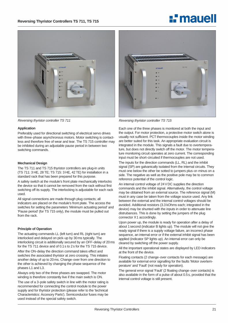
Reversing thyristor controller TS 711
ApplicationPreferably used for directional switching of electrical servo driveswith three-phase asynchronous motors. Motor switching is contact-less and therefore free of wear and tear. The TS 715 controller maybe inhibited during an adjustable pause period in between twoswitching commands.
Mechanical DesignThe TS 711 and TS 715 thyristor controllers are plug-in units(TS 711: 3 HE, 28 TE; TS 715: 3 HE, 42 TE) for installation in astandard rack that has been prepared for this purpose.
A safety switch at the module's front plate mechanically interlocksthe device so that it cannot be removed from the rack without firstswitching off its supply. The interlocking is adjustable for each rackused.
All signal connections are made through plug contacts; allindicators are placed on the module's front plate. The access theswitches for setting the parameters 'Minimum actuating period' and'Pause period' (for TS 715 only), the module must be pulled outfrom the rack.
Principle of OperationThe actuating commands LL (left turn) and RL (right turn) areinterlocked and delayed on pick-up by 30ms typically. Theinterlocking circuit is additionally secured by an OFF-delay of 20msfor the TS 711 device and of 0.1s to 2s for the TS 715 device.
After the ON-delay the direction command takes effect andswitches the associated thyristor at zero crossing. This initiatesanother delay of up to 20ms. Change-over from one direction tothe other is achieved by changing the phase sequence of thephases L1 and L3.
Always only two of the three phases are swapped. The motorwinding is therefore constantly live if the main switch is ON.
The use of a 3-pole safety switch in line with the motor rating isrecommended for connecting the control module to the powersupply and for thyristor protection (please refer to the 'technicalCharacteristics: Accesory Parts'). Semiconductor fuses may beused instead of the special safety switch.
Each one of the three phases is monitored at both the input andthe output. For motor protection, a protective motor switch alone isusually not sufficient. PCT thermocouples inside the motor windingare better suited for this task. An appropriate evaluation circuit isintegrated in the module. This signals a fault due to overtempera-ture, but does not directly switch off the motor. The motor tempera-ture monitoring circuit operates at zero current. The correspondinginput must be short-circuited if thermocouples are not used.
The inputs for the direction commands (LL, RL) and the inhibitsignal (SP) are galvanically isolated from the internal circuits. Theymust one below the other be sotted to jumpers plus-or-minus on aside. The negative as well as the positive pole may be to commonreference potential of the control logic.
An internal control voltage of 24VDC supplies the directioncommands and the inhibit signal. Alternatively, the control voltagemay be obtained from an external source. The reference signal (M)must in any case be taken from the voltage source used. Any linkbetween the external and the internal control voltages should beavoided. Additional resistors (3.3 kOhms each; integrated in thedevice) may be shunted with the inputs in order to attenuate linedistrubances. This is done by setting the jumpers of the plugconnector X1 accordingly.
Upon power up, the module is ready for operation after a delay ofabout 1second (indicator B lights up). The module will not give theready signal if there is a supply voltage failure, an incorrect phasesequence, an internal error or if the external inhibit signal has beenapplied (indicator SP lights up). An internal error can only becleared by switching off the power supply.
All the important operational states are displayed by LED indicatorsat the front of the device.
Floating contacts (2 change-over contacts for each message) areavailable for external error signalling for the faults 'Motor overtem-perature' and 'Fault' (not ready for operation).
The general error signal 'Fault' (2 floating change-over contacts) isalso available in the form of a pulse of about 0.5s, provided that theinternal control voltage is still present.
Reversing Thyristor Controllers 21
Reversing Thyristor Controllers TS 711, TS 715
Reversing thyristor controller TS 715

Technical Characteristics TS 711, TS 715
Power StageSupply voltage 3/N/PE AC 50Hz 400VL1, L2, L3 +10 %/-20 %,
clockwise rotationCan be disabled by means of a rotary switch on the front plate ofthe plug-in module. An automatic mechanical interlock ensures thatthe module cannot be removed from the rack as long as the switchis in the ON position.
Rated currentTS 711 3 x 6ATS 715 3 x 12A
Start-up currentTS 711 3 x 30A max.TS 715 3 x 60A max.
Motor-minimum-current 0.1A
Max. switching frequencyTS 711 ≤ 2400 operations/h up to 2.5A
≤ 1200 operations/h up to 6ATS 715 ≤ 600 operations/h up to 12A
Operating mode For actuating drives in DIN VDE 0530 intermittent operation,
duty cycle S4 - 10 %
Circuit ProtectionTS 711 10A max.TS 715 16A max.High-speed heavy-duty circuit breaker with the characteristic L acc.to VDE 0641, (which also serves as the main switch) orsemiconductor fuses for thyristor protection.
Actuating ModeRight or left rotation, pulse driven, with synchonization at zerocrossing.
Control StageInput signals +24VDC, galvanically isolatedLL, RL, SP from the local control voltage. The input voltages must be basic isolated acc. to DIN VDE 01601 signal +15V to +30V0 signal -15V to +5VCurrent consumption ≤ 2mADelay 30ms typically
(25ms ≤ tdelay ≤ 40ms)Internal +24VDC, only to be used for thecontrol voltage actuating commands RL/LL or
the external inhibit signal SPLoad 4mA max., short-circuit proofDo not connect any other control voltage if you are using theinternal control voltage.
MonitoringInhibited Upon failure of operationalactuating commands voltage (also if switch on front
plate is open).Upon failure of one or twophases.
Upon drop of internal supply voltage.Upon overheating inside the device.
Interruption Upon incorrect phase sequence.
Short-circuit Upon thyristor breakdown.These faults can only be cleared by switching off the supplyvoltage.
Fault indication Upon overtemperature of motorwinding.
Operating Mode Indicationthrough LEDs at the front plateSP (red) External inhibit signal ONSN (red) Mains faultSG (red) Fault inside the deviceSW (red) Overtemperature of motor
windingRL (yellow) Actuating command, RightLL (yellow) Actuating command, LeftB (green) Control and braking logics
enabled
Parameter Switches The switches for setting the parameters can only be accessed if themodule is removed from the rack.
Min. period of actuating cmds. 40ms to 180ms, in steps of tsmin at power output 20ms (2 to 9 periods)Factory setting 180ms = switch position 8
Pause period tp 0.1s to 2s, constantfor TS 715 only
Motor TemperatureEvaluation amplifier for 1 to 6 PCT thermocouples (acc. toDIN 44081) in the motor winding. Internal power supply.Attention:In a fault situation it might happen that this circuit reaches thepotential of the power circuit.
Total cold resistance ofthe monitoring loop 1.5kΩ typicallyThreshold value 2.5kΩ to 3.6kΩFall value 1.5kΩ to 2.3kΩ
Fault IndicationDevice ready for operation /at faultstatic 2 change-over contacts, floating
60VDC, 25VAC, 1A max.dynamic 2 change-over contacts, floating(at fault) 60VDC, 25VAC, 1A max.Motor winding temperature 2 change-over contacts, floatingstatic 60VDC, 25VAC, 1A max.
22 Reversing Thyristor Controllers

Time ResponseMin. actuating period LL, RL, SP 60ms
Min. pause between tworeversing commandsTS 711 20msTS 715 0.1s to 2s
Not ready for operationstatic ≥ 3s, delayed OFFdynamic ≥ 0.5s, pulse after OFF delay
Fault signalMotor temperature ≥ 2s, delayed ON
Electrical ConnectionsPower input and output Plug connectors DIN 41 612,
H-design, 15 pins, pre-mating plug contact for earth conductor
Signals Plug connectors DIN 41 612, F-design, 32 pins
Test voltagesSurge voltage testPower stage/ground 2.5kV, 1sControl stage/ground 1.0kV, 1sPower stage/control stage 2.5kV, 1sAll interfaces respectively control input or output, must be coveredto an additional insulation. Do not activate the device only with acurrent-operated protective device.
Operating ConditionsMounting position Horizontal, front plate
facing to the front
Permissible ambient temperatureoperation 0 °C to +55 °Ctransport and storage -40 °C to +70 °C
Humidity class DIN 40 040 G
Mechanical StrengthOscillates 1g /±0.075mm, 10Hz to 500HzDIN IEC 68 - 2 - 6 3x30 cycles, 1 Octave /min
Bump 15g/6ms/3x4000 shocksDIN IEC 68 - 2 - 29
Power lossTS 711 ≤ 30WTS 715 ≤ 50W
Standards/ RegulationsRated insulation voltages DIN VDE 0160Power stage 400VACControl stage 60VDCFault signalling outputs 60VDC, 25VAC
Overvoltage resistance Overvoltage resistance class IIDIN VDE 0160
Isolation between power and control stages DIN VDE 0160
Insulation Insulation class IDIN VDE 0100, section 410
Protection class IP 40 at the front panel, whenDIN 40 050 mounted in rack;
IP 00 at connections
Creepage distances and Pollution degree 2clearances DIN VDE 0110 Overvoltage class III
Interference immunity Intensity of test 3 for mains, DIN VDE 0843, sections 2 and 4 motor and control connections
HousingTS 711 Plug-in unit 3 HE, 28 TE TS 715 Plug-in unit 3 HE, 42 TEaccording to DIN 41 494, section 5, with PCBs inserted100mm x 160mm
DimensionsFront plateTS 711 141.9mm x 128.4mmTS 715 213.0mm x 128.4mm
Mounting depth 193.5mm (without handle) Protrusion of handle: 30mm max.
WeightTS 711 1.75kg TS 715 2.15kg
Ordering Details
Designation Order Reference
Reversing thyristor controllerTS 711 31 - 99 - 011
Reversing thyristor controllerTS 715 31 - 99 - 015
Reversing Thyristor Controllers 23

24 Reversing Thyristor Controllers
Accessory Parts
Safety switch for TS 711
Safety switch (by CMC)
Motor rated current Start-up Type / Magnetic trip(kW approx.) current rated current
≤ 2.5A/ (0.75kW) ≤ 10A QL3 6.0A 18A to 30A≤ 6.0A/ (1.5kW) ≤ 30A QC3 10.0A 50A to 100A
Rated switching capacity
Irated = 6A 10kA at 3 x 400/230V, 50Hz
Irated ≥ 10A 30kA at 3 x 400/230V, 50Hz
Safety switch for TS 705
≤ 6A/ (3kW) ≤ 25A QC 3 10A 50A to 100A≤ 12A (5.5kW) ≤ 50A QC 3 16A 80A to 160A
Rated switching capacity 30kA at 3 x 400/230V, 50Hz
Trip delay at short circuit 2ms approx.
Installation On standard railDIN EN 50022-35
Note
These safety switches are 3-pole quick-response heavy-dutycircuit breakers with trip characteristics adapted to semiconductors.Available without and with (option) auxiliary contacts (1NC + 1NO).Another tripping characteristic posible (option).
Terminal Connections
15-pin female multipoint connector DIN 41 612, H-design, order reference: 01 - 69 - 095
32-pin female multipoint connector DIN 41 612, F-design, order reference: 01 - 69 - 058
Note: The contacts of the plug connector X2 are counted inascending order, from bottom to top!
Subrack
19" subrack according to DIN 41 494, section 5; 3 HE, for theinsertion of 3 plug-in modules TS 701, equipped with 3 x 2multipoint connectors, or 2 plug-in modules TS 705, equipped with2 x 2 multipoint connectors.
Control Cubicle
Standard: 900mm x 2200mm x 500mm (W x H x D), doors onboth sides. Cable inlet at bottom or top. Suited for a maximum of24 units of type TS 711 or 16 units of type 715, inclusive of themain power switch, separate protection (safety switch) andterminals. Protection class: IP 20 (standard)

Reversing Thyristor Controllers 25
Block diagram TS 711, TS 715
Block Diagrams TS 711, TS 715
&
11
M
t
tsmintp *)
+
+ +
30b 24z
I >
B
32b30z 26b 26z28z 22z 28bX1 20b 20zX2 30d 26d 22d 18d4z
L1 L2 L3 N
LL RL
Control logic 24 V DC
SP M
Plug-inverification
-+--
-
voltage
Phase sequence
Phase position
SP
LL
RLControl logicsControl-
logics
SN SG
Fault, dynamicFault, static
voltage
SW
Motor temperature
X2: X1:
PE T1 T2 T3
22b 24b
Monitoringlogics
Q1
O I
PE
O I
2b 10b14d 10d 6d 24z 28z 6z 4z 6b 2z 4b 12z 10z 12b 8z 8b 18z 16b 18b 16z 14z 14b
I > I >
ϑ
∼−
*) In the TS 711 controller, there is no potentiometer tP

26 Reversing Thyristor Controllers
Dimension drawing TS 711 Dimension drawing TS 715
TS 711SP
SN
SG
SW
RL
LL
B
141.9
1277.45
27
128.
4
EIN
AUS
2
32
32
4
Connector X2 Connector X1
Front view
Rear view
Side view169.5
167 2.5
tsmin
Heat sink
30188.5
Lock
Position of female multipoint connectorand guide bead(seen from the front)
X1 X2
106.68 (21 TE)15.24
137.16 (27 TE)
141
111
30
106.68 (21 TE)
LL
B
TS 715
213
198.17.45
52.3
128.
4
2
32
32
4
Connector X2 Connector X1
177.8 (35TE)
Front view
Rear view
Side view169.5
167 2.5
tsmin
Heat sink
30
30
Lock
Position of female multipoint connectorand guide bead(seen from the front)
X1 X2
177.8 (35TE)15.24
208.28 (41TE)
tp
212.1
111
191
SP
SN
SG
SW
RL
LL
B
LL
B
EIN
AUS
Dimension Drawings TS 711, TS 715

Reversing Thyristor Controllers 27

Representatives
17.0700.01E94
Germany
Helmut Mauell GmbHAm Rosenhügel 1–7D-42553 VelbertTel.: +49 (0)20 53 /1 30Fax.: +49 (0)20 53 /1 36 53Internet: www.mauell.comE-Mail: [email protected]
For an up-to-date list of all our representa-tives and branch offices, please visit ourhomepage: www.mauell.com
Representatives andBranch Offices All Over The World:Abu Dhabi U.A.E.ArgentinaAustriaBelgiumBrazilCzech RepublicDenmarkFinlandFranceGreat BritainHungary
IranKoreaKuwaitNetherlandsNorwayPolandSingaporeSpainSwedenSwitzerlandTurkeyUSA