power electronics - philadelphia.edu.jo electronic... · power electronics single phase...
TRANSCRIPT
Power Electronics Single Phase Uncontrolled Half
Wave Rectifiers
1
Dr. Firas Obeidat
2
Table of contents
1 • Resistive Load
2
• R-L Load
3
• R-L Load with Freewheeling Diode
4
• Half Wave Rectifier with a Capacitor Filter
Dr. Firas Obeidat Faculty of Engineering Philadelphia University
3 Dr. Firas Obeidat Faculty of Engineering Philadelphia University
Introduction
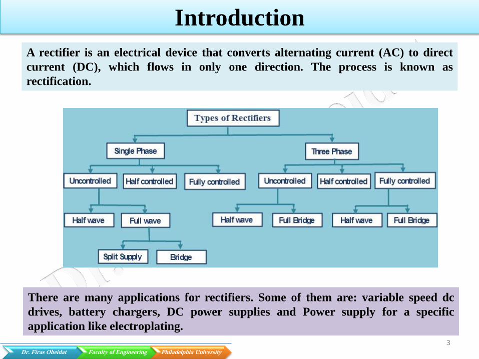
A rectifier is an electrical device that converts alternating current (AC) to direct
current (DC), which flows in only one direction. The process is known as
rectification.
There are many applications for rectifiers. Some of them are: variable speed dc
drives, battery chargers, DC power supplies and Power supply for a specific
application like electroplating.
4 Dr. Firas Obeidat Faculty of Engineering Philadelphia University
Resistive Load
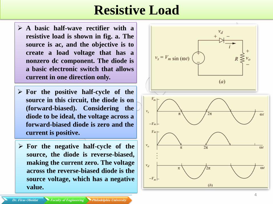
A basic half-wave rectifier with a
resistive load is shown in fig. a. The
source is ac, and the objective is to
create a load voltage that has a
nonzero dc component. The diode is
a basic electronic switch that allows
current in one direction only.
For the positive half-cycle of the
source in this circuit, the diode is on
(forward-biased). Considering the
diode to be ideal, the voltage across a
forward-biased diode is zero and the
current is positive.
For the negative half-cycle of the
source, the diode is reverse-biased,
making the current zero. The voltage
across the reverse-biased diode is the
source voltage, which has a negative
value.

5 Dr. Firas Obeidat Faculty of Engineering Philadelphia University
Resistive Load
The dc component Vo of the output voltage is the average value of a half-wave
rectified sinusoid
The dc component of the current for the purely resistive load is
The rms values of Vo and Io can be written as
Vdc=
Idc=
6 Dr. Firas Obeidat Faculty of Engineering Philadelphia University
Resistive Load
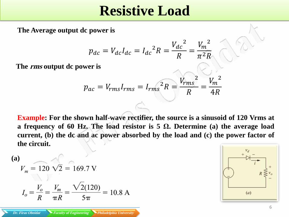
The Average output dc power is
𝑝𝑑𝑐 = 𝑉𝑑𝑐𝐼𝑑𝑐 = 𝐼𝑑𝑐2𝑅 =
𝑉𝑑𝑐2
𝑅=𝑉𝑚2
𝜋2𝑅
The rms output dc power is
𝑝𝑎𝑐 = 𝑉𝑟𝑚𝑠𝐼𝑟𝑚𝑠 = 𝐼𝑟𝑚𝑠2𝑅 =
𝑉𝑟𝑚𝑠2
𝑅=𝑉𝑚2
4𝑅
Example: For the shown half-wave rectifier, the source is a sinusoid of 120 Vrms at
a frequency of 60 Hz. The load resistor is 5 Ω. Determine (a) the average load
current, (b) the dc and ac power absorbed by the load and (c) the power factor of
the circuit.
(a)
7 Dr. Firas Obeidat Faculty of Engineering Philadelphia University
Resistive Load
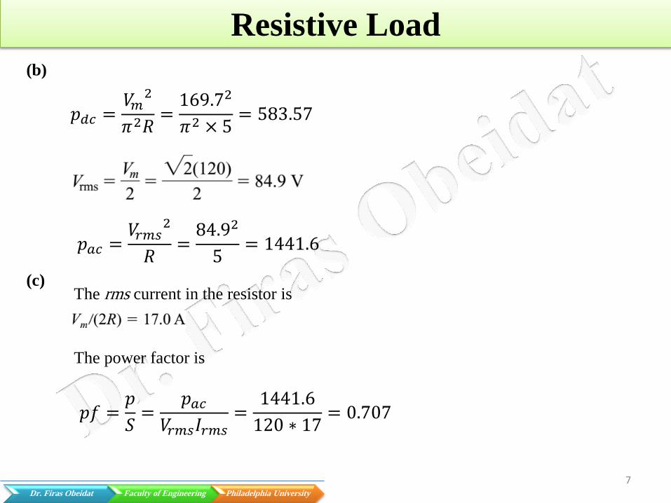
(b)
(c) The rms current in the resistor is
The power factor is
𝑝𝑑𝑐 =𝑉𝑚2
𝜋2𝑅=169.72
𝜋2 × 5= 583.57
𝑝𝑎𝑐 =𝑉𝑟𝑚𝑠
2
𝑅=84.92
5= 1441.6
𝑝𝑓 =𝑝
𝑆=
𝑝𝑎𝑐𝑉𝑟𝑚𝑠𝐼𝑟𝑚𝑠
=1441.6
120 ∗ 17= 0.707
8 Dr. Firas Obeidat Faculty of Engineering Philadelphia University
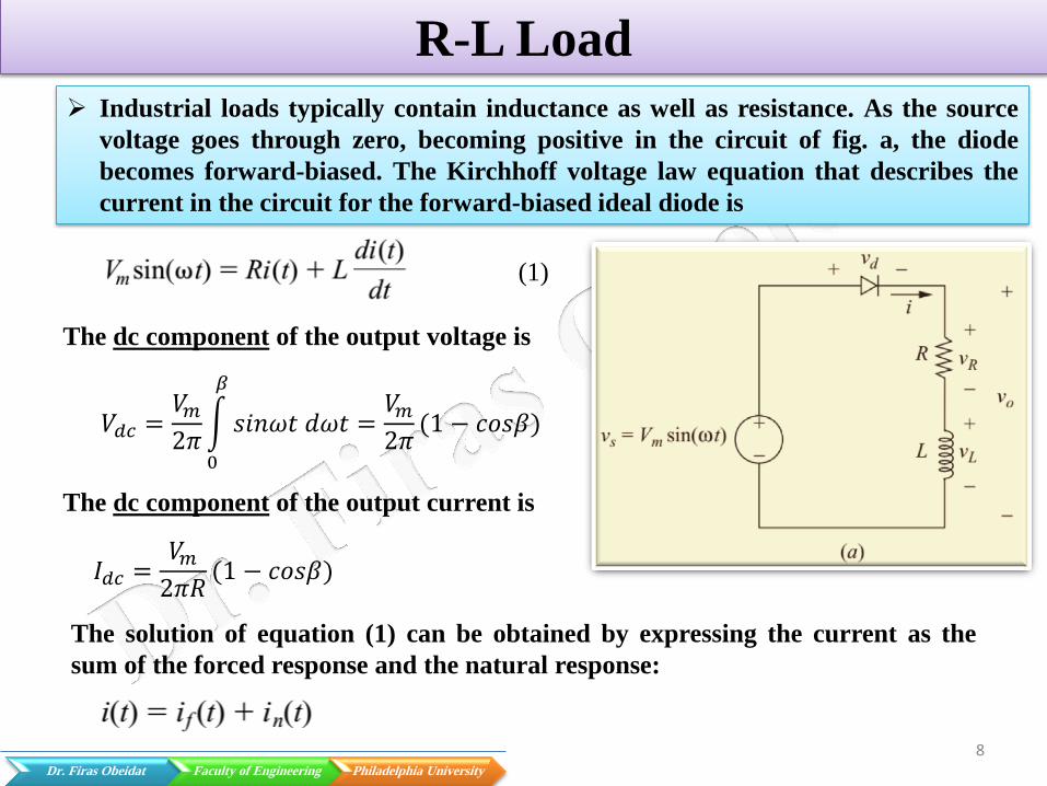
R-L Load
Industrial loads typically contain inductance as well as resistance. As the source
voltage goes through zero, becoming positive in the circuit of fig. a, the diode
becomes forward-biased. The Kirchhoff voltage law equation that describes the
current in the circuit for the forward-biased ideal diode is
The dc component of the output voltage is
𝑉𝑑𝑐 =𝑉𝑚2𝜋 𝑠𝑖𝑛𝜔𝑡 𝑑𝜔𝑡
𝛽
0
=𝑉𝑚2𝜋(1 − 𝑐𝑜𝑠𝛽)
The dc component of the output current is
𝐼𝑑𝑐 =𝑉𝑚2𝜋𝑅
(1 − 𝑐𝑜𝑠𝛽)
(1)
The solution of equation (1) can be obtained by expressing the current as the
sum of the forced response and the natural response:

9 Dr. Firas Obeidat Faculty of Engineering Philadelphia University
R-L Load
The forced response for this circuit is the
current that exists after the natural
response has decayed to zero. In this case,
the forced response is the steady-state
sinusoidal current that would exist in the
circuit if the diode were not present.
This steady-state current can be found from
phasor analysis, resulting in
Where
The natural response is the transient that
occurs when the load is energized. It is the
solution to the homogeneous differential
equation for the circuit without the source
or diode.

10 Dr. Firas Obeidat Faculty of Engineering Philadelphia University
R-L Load
For this first-order circuit, the natural response has the form
Adding the forced and natural responses gets the complete solution.
Where 𝜏 =
𝐿
𝑅 A= constant
The constant A is evaluated by using the initial condition for current:
t=0, i(𝜔t)=0.
Using the initial condition and equation (2) to evaluate A yields
(2)
11 Dr. Firas Obeidat Faculty of Engineering Philadelphia University
R-L Load
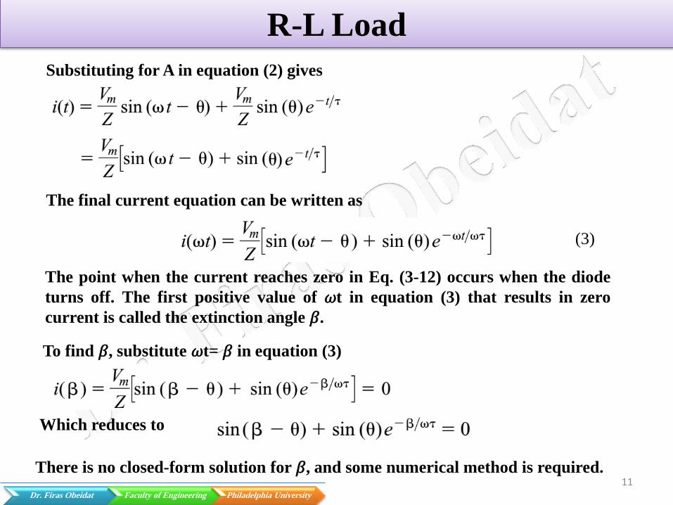
Substituting for A in equation (2) gives
The final current equation can be written as
The point when the current reaches zero in Eq. (3-12) occurs when the diode
turns off. The first positive value of 𝜔t in equation (3) that results in zero
current is called the extinction angle 𝛽.
(3)
To find 𝛽, substitute 𝜔t= 𝛽 in equation (3)
Which reduces to
There is no closed-form solution for 𝛽, and some numerical method is required.

12
R-L Load
To summarize, the current in the half-wave rectifier circuit with RL load is
expressed as
𝑉𝑑𝑐 =𝑉𝑚2𝜋 𝑠𝑖𝑛𝜔𝑡 𝑑𝜔𝑡
𝛽
0
=𝑉𝑚2𝜋(1 − 𝑐𝑜𝑠𝛽)
The dc component of the output current is
𝐼𝑑𝑐 = 𝐼𝑜 =𝑉𝑚2𝜋𝑅
(1 − 𝑐𝑜𝑠𝛽)
Or it can be found as

13 Dr. Firas Obeidat Faculty of Engineering Philadelphia University
R-L Load
The rms value of Io can be written as
Or it can be written as
𝑉𝑟𝑚𝑠 =1
2𝜋 (𝑉𝑚𝑠𝑖𝑛𝜔𝑡)
2 𝑑𝜔𝑡
𝛽
0
=𝑉𝑚2
4𝜋(𝛽 −
1
2𝑠𝑖𝑛2𝛽)
𝐼𝑟𝑚𝑠 =𝑉𝑟𝑚𝑠𝑍=
𝑉𝑟𝑚𝑠
𝑅2 + (𝜔𝐿)2=
1
𝑅2 + (𝜔𝐿)2
𝑉𝑚2
4𝜋(𝛽 −
1
2𝑠𝑖𝑛2𝛽)
14 Dr. Firas Obeidat Faculty of Engineering Philadelphia University
R-L Load
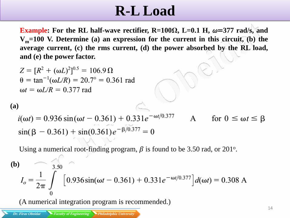
Example: For the RL half-wave rectifier, R=100Ω, L=0.1 H, 𝜔=377 rad/s, and
Vm=100 V. Determine (a) an expression for the current in this circuit, (b) the
average current, (c) the rms current, (d) the power absorbed by the RL load,
and (e) the power factor.
(a)
Using a numerical root-finding program, 𝛽 is found to be 3.50 rad, or 201o.
(b)
(A numerical integration program is recommended.)

15 Dr. Firas Obeidat Faculty of Engineering Philadelphia University
R-L Load
𝐼𝑑𝑐 = 𝐼𝑜 =𝑉𝑚2𝜋𝑅
1 − 𝑐𝑜𝑠𝛽 =100
2𝜋1001 − 𝑐𝑜𝑠201 = 0.308 𝐴
Io can be also found from
(c)
Irms can be also found from
(d)
(e)
Note that the power factor is not cosθ.
𝐼𝑟𝑚𝑠 =1
𝑅2 + (𝜔𝐿)2
𝑉𝑚2
4𝜋(𝛽 −
1
2𝑠𝑖𝑛2𝛽) =
1
106.9
1002
4𝜋(3.5 −
1
2𝑠𝑖𝑛7) = 0.489 A
16 Dr. Firas Obeidat Faculty of Engineering Philadelphia University
R-L Load with Freewheeling Diode
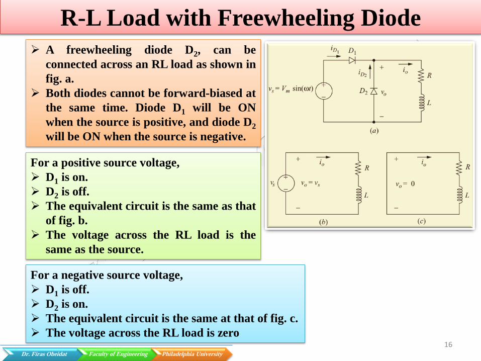
A freewheeling diode D2, can be
connected across an RL load as shown in
fig. a.
Both diodes cannot be forward-biased at
the same time. Diode D1 will be ON
when the source is positive, and diode D2
will be ON when the source is negative.
For a positive source voltage,
D1 is on.
D2 is off.
The equivalent circuit is the same as that
of fig. b.
The voltage across the RL load is the
same as the source.
For a negative source voltage,
D1 is off.
D2 is on.
The equivalent circuit is the same at that of fig. c.
The voltage across the RL load is zero

17 Dr. Firas Obeidat Faculty of Engineering Philadelphia University
R-L Load with Freewheeling Diode
Since the voltage across the RL load is
the same as the source voltage when the
source is positive and is zero when the
source is negative, the load voltage is a
half-wave rectified sine wave. Steady-
state load, source, and diode currents
are shown in the fig..
Example: Determine the average load
voltage and current for the circuit, where
R=2 Ω and L=25mH, Vm is 100 V, and the
frequency is 60 Hz.
18 Dr. Firas Obeidat Faculty of Engineering Philadelphia University
Half Wave Rectifier with a Capacitor Filter
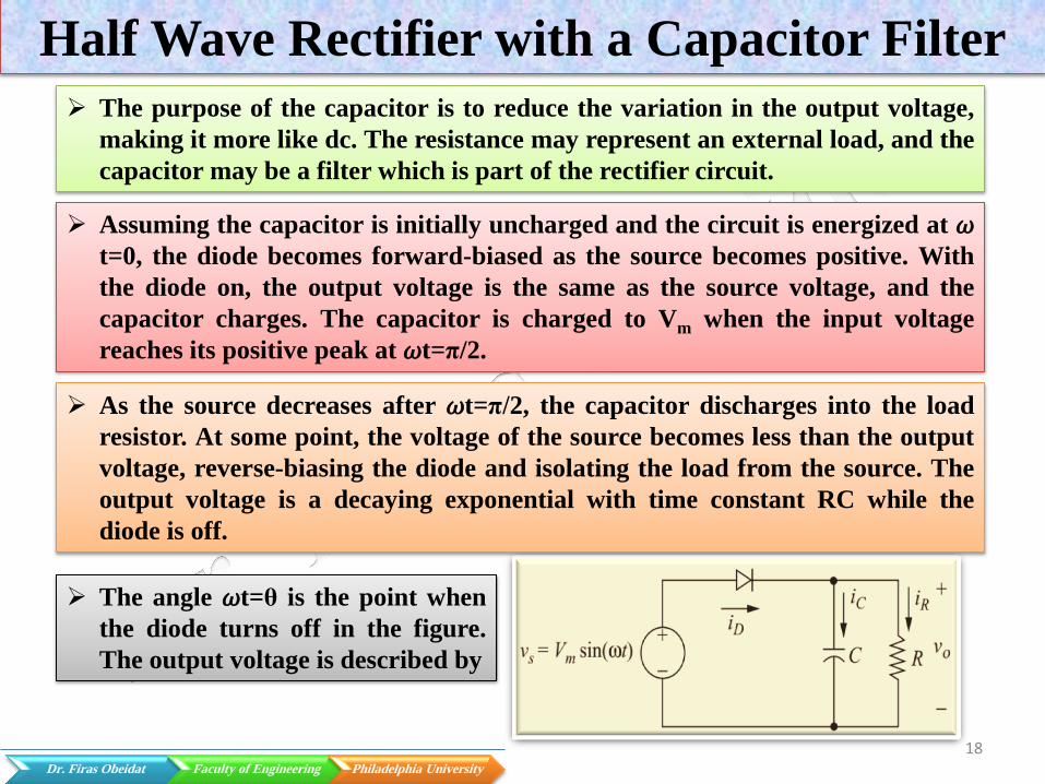
The purpose of the capacitor is to reduce the variation in the output voltage,
making it more like dc. The resistance may represent an external load, and the
capacitor may be a filter which is part of the rectifier circuit.
Assuming the capacitor is initially uncharged and the circuit is energized at 𝜔t=0, the diode becomes forward-biased as the source becomes positive. With
the diode on, the output voltage is the same as the source voltage, and the
capacitor charges. The capacitor is charged to Vm when the input voltage
reaches its positive peak at 𝜔t=π/2.
As the source decreases after 𝜔t=π/2, the capacitor discharges into the load
resistor. At some point, the voltage of the source becomes less than the output
voltage, reverse-biasing the diode and isolating the load from the source. The
output voltage is a decaying exponential with time constant RC while the
diode is off.
The angle 𝜔t=θ is the point when
the diode turns off in the figure.
The output voltage is described by
19 Dr. Firas Obeidat Faculty of Engineering Philadelphia University
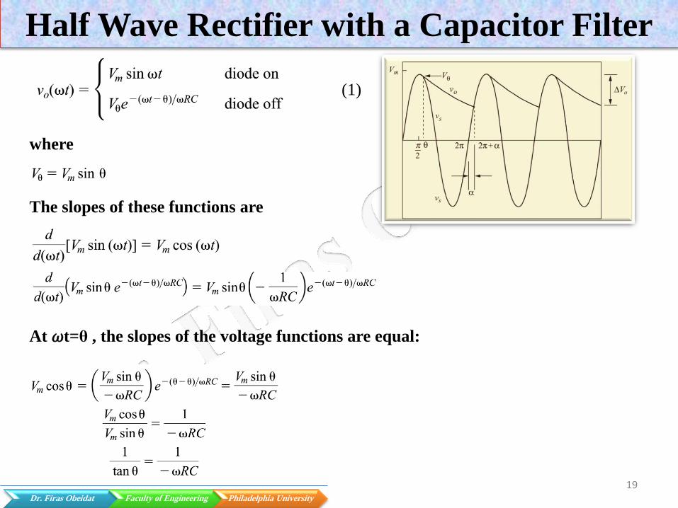
Half Wave Rectifier with a Capacitor Filter
where
The slopes of these functions are
At 𝜔t=θ , the slopes of the voltage functions are equal:
(1)

20 Dr. Firas Obeidat Faculty of Engineering Philadelphia University
Half Wave Rectifier with a Capacitor Filter
Solving for θ and expressing θ so it is in the proper quadrant,
In practical circuits where the time constant is large,
The angle at which the diode turns on in the second period, 𝜔t=2π+α, is the point
when the sinusoidal source reaches the same value as the decaying exponential
output:
The above equation must be solved numerically for α.
The current in the resistor is calculated from
𝑖𝑅 =𝑣𝑜𝑅
The current in the capacitor is calculated from
Or

21 Dr. Firas Obeidat Faculty of Engineering Philadelphia University
Half Wave Rectifier with a Capacitor Filter
Using vo from equation (1) we, get
The source current, which is the same as the diode current, is
Peak capacitor current occurs when the diode turns on at 𝜔t=2π+α. From
equation (2)
(2)
Resistor current at 𝜔t=2π+α is obtained from equation (1)
Peak diode current is
22 Dr. Firas Obeidat Faculty of Engineering Philadelphia University
Half Wave Rectifier with a Capacitor Filter
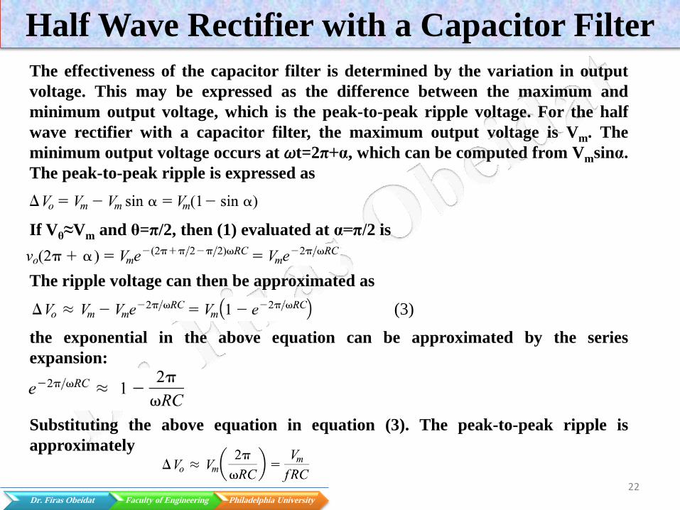
The effectiveness of the capacitor filter is determined by the variation in output
voltage. This may be expressed as the difference between the maximum and
minimum output voltage, which is the peak-to-peak ripple voltage. For the half
wave rectifier with a capacitor filter, the maximum output voltage is Vm. The
minimum output voltage occurs at 𝜔t=2π+α, which can be computed from Vmsinα.
The peak-to-peak ripple is expressed as
If Vθ≈Vm and θ=π/2, then (1) evaluated at α=π/2 is
The ripple voltage can then be approximated as
the exponential in the above equation can be approximated by the series
expansion:
(3)
Substituting the above equation in equation (3). The peak-to-peak ripple is
approximately
23 Dr. Firas Obeidat Faculty of Engineering Philadelphia University
Half Wave Rectifier with a Capacitor Filter
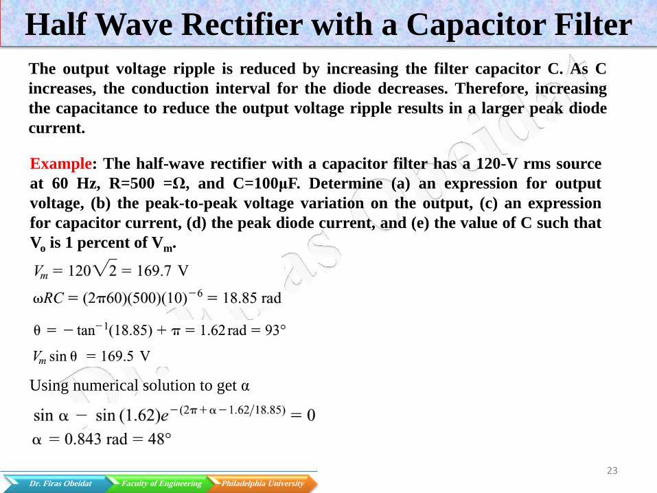
The output voltage ripple is reduced by increasing the filter capacitor C. As C
increases, the conduction interval for the diode decreases. Therefore, increasing
the capacitance to reduce the output voltage ripple results in a larger peak diode
current.
Example: The half-wave rectifier with a capacitor filter has a 120-V rms source
at 60 Hz, R=500 =Ω, and C=100μF. Determine (a) an expression for output
voltage, (b) the peak-to-peak voltage variation on the output, (c) an expression
for capacitor current, (d) the peak diode current, and (e) the value of C such that
Vo is 1 percent of Vm.
Using numerical solution to get α
24 Dr. Firas Obeidat Faculty of Engineering Philadelphia University
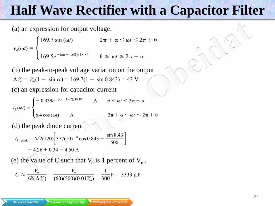
Half Wave Rectifier with a Capacitor Filter
(a) an expression for output voltage.
(b) the peak-to-peak voltage variation on the output
(c) an expression for capacitor current
(d) the peak diode current
(e) the value of C such that Vo is 1 percent of Vm.

25