power edger - echo · pdf filepower edger operator's manual models pe-2000 type 1/1e ......
TRANSCRIPT

POWER EDGEROPERATOR'S MANUAL 1
Power EdgerOperator's Manual
MODELS PE-2000 Type 1/1ESerial Number 001001 & Up
PE-2000 Type 2ESerial Number 508036 & Up
8986105883208/01
X7502124502
PE-2400 Type 1/1ESerial Number 001001 & Up
PE-3100 Type 1/1ESerial Number 001001 & Up
WARNING DANGERRead rules for safe operation and instructions carefully. ECHO provides anOperator's Manual and a Safety Manual. Both must be read and understood forproper and safe operation.

2INTRODUCTION
Welcome to the ECHO family. This ECHO product was designed and manufactured to provide long life and on-the-job-dependability. Read and understand this manual and the SAFETY MANUAL you found in the same package. You willfind both easy to use and full of helpful operations tips and SAFETY messages.
THE OPERATOR'S MANUALContains specifications and information for operation, starting,stopping, maintenance, storage and assembly specific to this product.
THE SAFETY MANUALExplains possible hazards involved with the use of Edgers and themeasures you should take to make their use safer.
TABLE OF CONTENTS
Introduction ............................................................... 2- The Operator's Manual .............................................. 2
- The Safety Manual ..................................................... 2
Manual Safety Symbols and Important Information .. 3Safety ......................................................................... 3
- Decals .................................................................. 4- International Symbols ......................................... 4
Safety Instructions .................................................... 4- Personal Condition and Safety Equipment .......... 4- Extended Operation/Extreme Conditions ............. 5- Equipment ........................................................... 5- Safe Operation ..................................................... 6
Emission Control ........................................................ 6Description ................................................................ 7
- Contents .............................................................. 7Assembly ................................................................. 10
- Specifications .................................................... 10- Drive Shaft/Power Head .................................... 11- Throttle Cable .................................................... 11- Loop Handle ...................................................... 12
Pre-Operation ........................................................... 13- Fuel ................................................................... 13
Operation ................................................................. 14- Starting Cold Engine ......................................... 14- Starting Warm Engine ....................................... 15- Stopping Engine ................................................ 15
- Operating Techniques ....................................... 16Maintenance ............................................................ 17
- Skill Levels ........................................................ 17- Maintenance Intervals ...................................... 17- Air filter ............................................................. 18- Fuel Filter .......................................................... 18- Spark Plug ......................................................... 19- Cooling System ................................................. 19- Exhaust System ................................................. 20- Carburetor Adjustment Emission ...................... 21- Carburetor Adjustment Non Emission .............. 22- Lubrication ........................................................ 23
Troubleshooting ...................................................... 25Storage ..................................................................... 26Servicing Information ............................................... 28
- Parts .................................................................. 28- Service ............................................................... 28- Echo Consumer Product Support ...................... 28- Warranty Card ................................................... 28- Additional or Replacement Manuals ................. 28
Specifications, descriptions, and illustrative material in thisliterature are as accurate as known at the time of publication,but are subject to change without notice. Illustrations mayinclude optional equipment and accessories, and may notinclude all standard equipment.
Copyright© 2001 By Echo, IncorporatedAll Rights Reserved.

POWER EDGEROPERATOR'S MANUAL 3
The circle with the slash symbol means whateveris shown within the circle is prohibited.
This symbol accompanied by the words WARNING andDANGER calls attention to an act or condition that canlead to serious personal injury to operator and bystanders.
MANUAL SAFETY SYMBOLS AND IMPORTANT INFORMATION
Throughout this manual and on the product itself, you will find safetyalerts and helpful information messages preceded by symbols or keywords. The following is an explanation of those symbols and keywords.
IMPORTANTThe enclosed message provides informationnecessary for the protection of the unit.
NOTEThis enclosed message provides tips for use,care and maintenance of the unit.
SAFETY
DECALSLocate these safety decals on your unit. The complete unit illustrationfound in the "DESCRIPTION" section will help you locate them. Makesure the decals are legible and that you understand and follow theinstructions on them. If a decal cannot be read, a new one can beordered from your ECHO Dealer. See PARTS ORDERING instructionsfor specific information.
These decals are in English only:
Shaft Decal
P/N 89016025560
P/N 89016052631
P/N 89016006361
IMPORTANT NOTE
Guard Decal

4INTERNATIONAL SYMBOLS
SAFETY INSTRUCTIONS
PERSONAL CONDITION AND SAFETY EQUIPMENT
WARNING DANGEREdger users risk injury to themselves and others if the edger is used improperly or safety precautions are notfollowed. Proper clothing and safety gear must be worn when operating an edger.
Eye ProtectionWear eye protection that meets ANSI Z87.1 or CE require-ments whenever you operate the edger.
Hand ProtectionWear no-slip, heavy-duty work gloves to improve yourgrip on the edger handles. Gloves also reduce thetransmission of machine vibration to your hands.
Hearing ProtectionECHO recommends wearing hearing protection wheneverunit is used.
Proper ClothingWear snug fitting, durable clothing:• Pants should have long legs, shirts with long sleeves.• DO NOT WEAR SHORTS,• DO NOT WEAR TIES, SCARVES, JEWELRY.
Wear sturdy work shoes with non-skid soles:• DO NOT WEAR OPEN TOED SHOES,• DO NOT OPERATE UNIT BAREFOOTED.
Hot Humid WeatherHeavy protective clothing can increase operator fatiguewhich may lead to heat stroke. Schedule heavy work forearly morning or late afternoon hours when temperaturesare cooler.
Symboldescription/application
Symbol form/shape
Symboldescription/application
Symbol form/shape
HotSurface
Carburetoradjustment- Idle speed
Carburetoradjustment
- High speedmixture
Symboldescription/application
Symbol form/shape
Symboldescription/application
Symbol form/shape
Read and understandOperator's Manual.
Wear eyes, ears andhead protection
Emergency stop
Fuel and oil mixture
Finger Severing
Carburetoradjustment- Low speed
mixture
Safety/Alert
Avoid all powerlines. This unit is
not insulatedagainst electrical
current.
Wear handprotection. Use
two handed.
DO NOT smokenear fuel.
DO NOT allowflames or sparks
near fuel.
Wear slipresistant foot
wear.
Engine chokecontrol.
IgnitionON/OFF
Primer bulb
Keep bystanders away15 m (50 ft.)
Keep feet awayfrom blade
Thrownobjects
Direction ofblade

POWER EDGEROPERATOR'S MANUAL 5
EXTENDED OPERATION/EXTREME CONDITIONS
Vibration and ColdIt is believed that a condition called Raynaud’s Phenomenon, whichaffects the fingers of certain individuals, may be brought about byexposure to vibration and cold. Exposure to vibration and cold maycause tingling and burning sensations, followed by loss of color andnumbness in the fingers. The following precautions are stronglyrecommended because the minimum exposure which might trigger theailment is unknown.
• Keep your body warm, especially the head, neck, feet, ankles, hands,and wrists.
• Maintain good blood circulation by performing vigorous armexercisesduring frequent work breaks, and also by not smoking.
• Limit the hours of operation. Try to fill each day with jobs whereoperating the edger or other hand-held power equipment is notrequired.
• If you experience discomfort, redness, and swelling of the fingers,followed by whitening and loss of feeling, consult your physicianbefore further exposing yourself to cold and vibration.
Repetitive Stress InjuriesIt is believed that overusing the muscles and tendons of the fingers,hands, arms, and shoulders may cause soreness, swelling, numbness,weakness, and extreme pain in those areas. Certain repetitive handactivities may put you at a high risk for developing a Repetitive StressInjury (RSI). An extreme RSI condition is Carpal Tunnel Syndrome(CTS), which could occur when your wrist swells and squeezes a vitalnerve that runs through the area. Some believe that prolonged exposureto vibration may contribute to CTS. CTS can cause severe pain formonths or even years.
To reduce the risk of RSI/CTS, do thefollowing:
• Avoid using your wrist in a bent, extendedor twisted position. Instead try to maintaina straight wrist position. Also, whengrasping, use your whole hand, not justthe thumb and index finger.
• Take periodic breaks to minimize repetitionand rest your hands.
• Reduce the speed and force with whichyou do the repetitive movement.
• Do exercises to strengthen the hand andarm muscles.
• Immediately stop using all power equip-ment and consult a doctor if you feeltingling, numbness or pain in the fingers,hands, wrists, or arms. The sooner RSI/CTS is diagnosed, the more likely perma-nent nerve and muscle damage can beprevented.
EQUIPMENT
• Check unit for loose/missing nuts, bolts and screws. Tighten and/orreplace as needed.
• Inspect fuel lines, tank and area around carburetor for fuel leaks. DONOT operate unit if leaks are found.
• Inspect shield for damage and is securely in place. Replace if shield isdamaged or missing.
• Check that the cutting attachment is firmly attached and in safeoperating condition.
• Check that front handle is adjusted for safe, comfortable operation.See Assembly for proper adjustment.
• Keep exhaust area clear of flammable debris. Avoid contact duringand immediately after operation.

6SAFE OPERATION
WARNING DANGERDo not operate this product indoors or in inadequately ventilatedareas. Engine exhaust contains poisonous emissions and can causeserious injury or death.
• Provide all operators of this equipment with the Operator's Manualand Safety Manual for instructions on safe operation.
Keep A Firm Grip• Hold the left and right handles with both hands, with thumbs and
fingers tightly encircling the handles
Keep A Solid Stance• Maintain footing and balance at all times. Do not stand on slippery,
uneven or unstable surfaces. Do not work in odd positions or onladders. Do not over-reach.
An Emission Control Label is located on the engine. (This is an EXAMPLE ONLY, information on label varies by enginefamily).
EMISSION CONTROL
The emission control system for this engine is EM (Engine Modification).
IMPORTANT ENGINE INFORMATIONENGINE FAMILY: TEH024UB24RCDISPLACEMENT: 23.6 CCTHIS ENGINE MEETS U.S. EPA PH1 AND 1996 -1998 CALIFORNIA EMISSION REGULATIONSFOR ULGE ENGINES. REFER TO OWNER'SMANUAL FOR MAINTENANCE SPECIFICATIONSAND ADJUSTMENTS.

POWER EDGEROPERATOR'S MANUAL 7
20 21
DESCRIPTIONThe ECHO product you purchased has been factory pre-assembled for your convenience. Due to packaging restrictions,shield installation and positioning of the front handle are necessary.
After opening the carton, check for damage. Immediately notify your retailer or ECHO Dealer of damaged or missingparts. Use the contents list to check for missing parts.
CONTENTS__1, Edger Assembly__1, Power Head__1, Drive Shaft Assembly__1, Plastic Bag (Co-Pack)__1, Operators Manual__1, Safety Manual__1, Warranty Registration Card__1, ECHO Emissions and Warranty Statement__1, 50:1 1 Gal. ECHO Oil Mix__1, Front Handle__2, bolt 5x40 mm__2, nut 5__1, split pin__1, Scrench (Combination Spark Plug Socket/Screwdriver__1, Locking Tool__1, 10 mm Spanner Wrench__Safety Glasses
PE-2000
1
2
3
45
6 7
8
9
10
11
12
13
14
15
1617
1819

820 21CONTENTS
__ 1, Edger Assembly__ 1, Power Head__ 1, Drive Shaft Assembly__ 1, Plastic Bag (Co-Pack)__ 1, Operators Manual__ 1, Safety Manual__ 1, Warranty Registration Card__ 1, ECHO Emissions and Warranty Statement__ 1, 50:1 1 Gal. ECHO Oil Mix__ 1, Front Handle__ 4, 5X35 mm screws__ 4, 5 mm nuts__ 1, Scrench (Combination Spark Plug Socket/Screwdriver__ 1, split pin__ 1, 3 mm Hexagon Wrench__ 1, Locking Tool__ 1, 10 mm Spanner Wrench__ Safety Glasses
PE-2400PE-3100
1
2
3
45
6 7
8
9
10
1213
14
15
1617
18
19 11

POWER EDGEROPERATOR'S MANUAL 9
1. TOP GUARD - Protects arm from the hot engine.
2. FRONT HANDLE - The front handle can be repositioned for comfortable operation by loosening the screws andmoving the handle.
3. SHAFT DECAL (See page 3)
4. GUARD DECAL (See page 3)
5. DEBRIS SHIELD/FLAP - Mounted over the cutting attachment. Helps protect operator by deflecting debrisproduced during the edging operation.
6. BLADE - Rotates to provide cutting action.
7. WHEEL - Adjustable up/down, sets depth of blade.
8. DRIVE SHAFT ASSEMBLY - Contains a specially designed liner and the flexible drive shaft.
9. THROTTLE TRIGGER - Spring loaded to return to idle when released. When accelerating, press trigger graduallyfor best operating technique.
10. GRIP - Rear (right hand) handle.
11. STOP SWITCH -PE-2000 - "Toggle Switch" mounted on the engine. Move switch UP to RUN, DOWN to STOP.PE-2400/3100 - "Slide Switch" mounted on top of the throttle Trigger Housing. Move switch FORWARD to RUN,BACK to STOP.
12. CHOKE - The choke control is located on the top of the air filter case (PE-2400, 3100), or on the side of the air filtercase (PE-2000).PE-2000 - Move lever to "COLD START" to close choke for cold starting. Move lever to "RUN" position to openchoke.PE-2400/3100 - Pull choke knob up to close choke for cold starting. Push knob down to "RUN" position to openchoke.
13. SPARK PLUG - Provides spark to ignite fuel mixture.
14. MUFFLER/SPARK ARRESTOR -The spark arrestor muffler controls the exhaust noise and prevents hot, glowingparticles of carbon from leaving the muffler.
15. FUEL TANK - Contains fuel and fuel filter.
16. RECOIL STARTER HANDLE - Pull recoil handle slowly until starter engages, then quickly and firmly. DO NOT lethandle snap back or damage to unit will occur.
17. FUEL TANK CAP - Cover and seals fuel tank.
18. PRIMER BULB - Pumping primer bulb before starting engine draws fresh fuel from the fuel tank priming the carbure-tor for starting. Pump primer bulb until fuel is visible and flows freely in the clear fuel tank return line. Pump bulb anadditional 4 or 5 times.
19. AIR CLEANER - Contains replaceable felt element.
20. OPERATORS MANUAL - Read and understand this manual before assembly or operation. Keep manual in a safelocation for future reference, i.e., operation, maintenance, storage and specifications.
21. SAFETY MANUAL - Read and understand this manual before assembly or operation, and keep in a safe place forfuture reference to learn proper, safe operating techniques.

10ASSEMBLY
SPECFICATIONS
LEDOM E2/E10002-EP E1/10042-EP E1/10013-EP
htgneL ).ni0.96(mm3571 ).ni7.96(mm0771 ).ni7.07(mm5971
htdiW ).ni0.31(mm033 ).ni0.31(mm033 ).ni0.31(mm033
thgieH ).ni8.11(mm003 ).ni8.11(mm003 ).ni8.11(mm003
)daehrettuc/wyrd(thgieW ).bl2.21(gk5.5 ).bl0.31(gk9.5 ).bl6.51(gk1.7
epyTenignE enigneenilosagrednilycelgnis,ekorts-owt,deloocriA
eroB ).ni862.1(mm2.23 ).ni43.1(mm0.43 ).ni24.1(mm0.63
ekortS ).ni420.1(mm0.62 ).ni420.1(mm0.62 ).ni81.1(mm0.03
tnemecalpsiD ).ni.uc92.1(cc2.12 ).ni.uc44.1(cc6.32 ).ni.uc98.1(cc5.03
tsuahxE relffuMrotserrAkrapS*
egrup/wmgarhpaidroterubraC U1CledomamaZ TWledomorblaW TWledomorblaW
metsySnoitingI )noitingiegrahcsidroticapac(IDC
gulPkrapS ,A7-MPBKGN).ni620.0(mm56.0
Y7-JCnoipmahCroY7-MPBKGN).ni620.0(mm56.0
leuF )liOekorts-owTdnaenilosaG(dexiM
oitaRliO/leuF lioenignedeloocriaekorts-owt,ecnamrofrePhgiHOHCE1:05
enilosaG %01nahterom,lohoclalyhtemgniniatnocleufesuTONOD.dedaelnuenatcO98.EBTM%51rolohoclalyhte
liO lioenignedeloocriaekorts-owt,ecnamrofrePhgiHOHCE1:05
yticapaCknaTleuF ).zo.lfSU0.41(.til4.0 ).zo.lfSU0.41(.til4.0 ).zo.lfSU1.72(.til8.0
metsySretratS retratSdniweRcitamotuA
hctulC epyTlagufirtneC
tfahSevirD tfahselbixelf.ni4/1
noitceriDnoitatoR edismorfdeweivesiwkcolC
daeHregdE edalblateM
htgneLedalB ).ni0.8(mm2.302
htdiWedalB ).ni2(mm8.05
ssenkcihTedalB ).ni9.0(mm5.2 ).ni081.0(mm5.4
eldnaH pirG-thgiR,pool-D-tfeL
noitcudeRnoitarbiV noihsuCrebbuR
deepSeldI MPR0013-0052 MPR0013-0052 MPR0003-0042
deepSelttorhTnepOediW MPR00001-0009 MPR00011-00001 MPR00011-0059

POWER EDGEROPERATOR'S MANUAL 11
DRIVE SHAFT/POWER HEADTools Required: 8mm x 10mm Open End Wrench (PE-2000, PE-2400),
4mm Hex Wrench (PE-3100)
1. Stand engine on a level surface.
2a. (PE-2000/2400) Loosen the two bolts (A) at drive shaft end ofengine.
2b. (PE-3100) Loosen two bolts (A) at drive shaft end of engine andremove center drive shaft location bolt (B).
3. Carefully fit drive shaft assembly to engine, making sure that innerdrive shaft engages into clutch mount.
NOTEThe line on the drive shaft housing must be in contact with theengine (arrow on drive shaft indicates line).
4a. (PE-2000/2400) Rotate the drive shaft housing until edger housing isin line with the engine.
4b. (PE-3100) Rotate drive shaft housing until locating hole lines up withcenter location hole in clamp and install center bolt (B).
5. Tighten bolts (A).
THROTTLE LINKAGETools Required: 8mm x 10mm Open End Wrench (All Models), 3mmWrench (PE-2400)
1. Close choke and remove air filter cover.
2. Loosen nut (A) and place threaded end of throttle linkage inbracket slot. Finger tighten nut (A). Place inner cable in slot ofcarburetor (B).
3. Check throttle action, for freedom of movement and that the innerthrottle linkage allows the carburetor throttle plate (E) to return toidle stop. Adjust cable nut counter clockwise to increase innerthrottle lnkage length and allow throttle plate to rest against stop.
4. Tighten nut (A).
A
AA
B
PE-2400
PE-3100
PE-2000
PE-2000
A

12
PE-2400PE-3100
FRONTHANDLE
PE-2400
PE-3100
NOTESteps 5, 6 & 7 required for PE-2400 and PE-3100 only.
5. Connect ignition leads (C).
6. (PE-2400) Secure ground lead under screw (D) on housing.
7. Install air filter and cover.
FRONT HANDLE
Tools Required:Cross-Head Screwdriver
(PE-2000)1. Assemble loop handle (A) and bottom bracket (B) loosely using
screws (C) and nuts (D) to loop handle collar (E), located on driveshaft (F).
2. Position handle in comfortable operating position and tightenscrews (C).
(PE-2400, 3100)1. Assemble front handle and bracket loosely to drive shaft.
2. Position front handle in comfortable operating position and tightenscrews.
PE-2000
LOOPHANDLE
A
B
C
D
E
F

POWER EDGEROPERATOR'S MANUAL 13
PRE-OPERATION
FUEL
Fuel Requirements
Gasoline - Use 89 Octane [ (R+M) ÷ 2 ] gasoline known to be goodquality. Gasoline may contain up to 10% Ethanol (grain alcohol) or 15%MTBE (methyl tertiary-butyl ether). Gasoline containing methanol(wood alcohol) is NOT approved.
Two-Stroke Oil - Two Stroke Oil - A two-stroke engine oil meetingISO-L-EGD (ISO/CD 13738) and J.A.S.O. FC Standards, must be used.Echo brand Premium 50:1 oil meets these standards. Engine problemsdue to inadequate lubrication caused by failure to use an ISO-L-EGDand J.A.S.O. FC certified oil, such as Echo Premium 50:1 Two-stroke Oil,will void the two-stroke engine warranty. (Emission related parts onlyare covered for two years, regardless of two-stroke oil used, per thestatement listed in the EPA Phase I/California Emission Defect War-ranty Explanation.)
IMPORTANTEcho Premium 2-Stroke Oil may be mixed at 50:1 ratio for applicationin all Echo engines sold in the past regardless of ratio specified inthose manuals.
Mixing Instructions1. Fill an approved fuel container with half of the required amount of
gasoline.2. Add 2-stroke oil to gasoline.3. Close container and shake to mix oil with gasoline.4. Add remaining gasoline and remix.5. Install fuel container cap and wipe any spilled fuel from container
and surrounding area.
Handling Fuel
WARNING DANGERFuel is VERY flammable. Use extreme care when mixing, storing orhandling, or serious personal injury may result.• Use an approved fuel container.• DO NOT smoke near fuel.• DO NOT allow flames or sparks near fuel.• Fuel tanks/cans may be under pressure. Always loosen fuel
caps slowly allowing pressure to equalize.• NEVER refuel a unit when the engine is HOT!• NEVER refuel a unit with the engine running.• DO NOT fill fuel tanks indoors. ALWAYS fill fuel tanks outdoors
over bare ground.• Securely tighten fuel cap after refueling.• Inspect for fuel leakage. If fuel leakage is found, do not start or
operate unit until leakage is repaired.
IMPORTANTSpilled fuel is a leading cause ofhydrocarbon emissions. Some statesmay require the use of automatic fuelshut-off containers to reduce fuelspillage. Contact your ECHO dealer forordering information.
After refueling• Wipe any spilled fuel from the unit.• Move at least 3 m (10 ft.) from refueling
location before starting the engine.
After use• DO NOT store a unit with fuel in its tank.
Leaks can occur. Return unused fuel to anapproved fuel storage container.
StorageFuel storage laws vary by locality. Contactyour local government for the laws affectingyour area. As a precaution, store fuel in anapproved, air tight container. Store in a wellventilated, unoccupied building, away fromsparks and flames. Do not store fuel longerthan 30 days.
IMPORTANTStored fuel ages. Do not mix more fuelthan you expect to use in thirty (30)days, ninety (90) days when a fuelstabilizer is added.
IMPORTANTStored two-stroke fuel may separate.ALWAYS shake fuel container thor-oughly before each use.

14OPERATION
STARTING COLD ENGINENOTE• Check unit for loose nuts, bolts and screws before starting.• Always clear work area of debris before starting operation.• Always position the unit firmly on the ground before starting.• When pulling recoil starter rope, use short pulls, 1/2 to 2/3 of
rope length.• Do not allow the recoil starter handle to snap back against the
housing.• Always hold the unit firmly.
WARNING DANGERWhen engine starts, the blade may rotate, even with throttle trigger inidle (Release) position.
1. Stop SwitchMove stop switch button (A) away from the STOP position.
2. ChokeMove choke (B) to "Cold Start" position.
3. Primer BulbPump primer bulb (C) until fuel is visible in the "Clear" fuel returnline. Pump bulb an additional 4 or 5 times.
WARNING DANGERInspect starting area for hazards such as rocks, glass, debris etc.which could be contacted by the cutting attachment when starting.Keep helpers and bystanders at least 15 m (50 ft.) from startingarea, otherwise serious personal injury may result.
4. Recoil StarterLay trimmer on a flat, clear area. Firmly grasp throttle grip with lefthand and fully depress throttle trigger to wide open position.Rapidly pull recoil starter handle/rope (D) until engine fires (ormaximum five [5] pulls).
5. ChokeAfter engine fires (or five [5] pulls), move choke lever back to"RUN" position. Hold throttle trigger fully depressed and pullrecoil starter handle/rope until engine starts and runs. Releasethrottle trigger and allow unit to warn up at idle for several minutes.
NOTEIf engine does not start with choke in "RUN" position after 4 pulls,repeat instructions.
6. Throttle TriggerAfter engine warm up, gradually depress throttle trigger to increaseengine RPM to operating speed.
PE-2000
PE-2400PE-3100
A
A
PE-2000
C
B
D
PE-2400PE-3100
B
C
D
POWER EDGEROPERATOR'S MANUAL 15
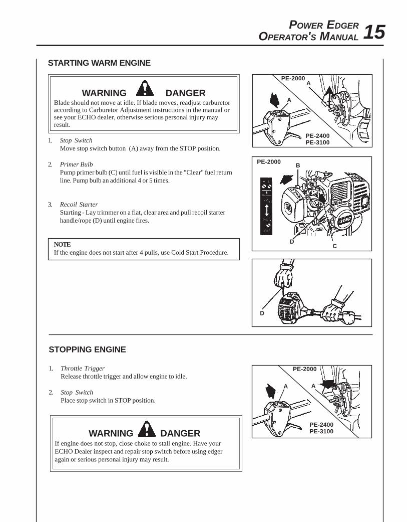
STARTING WARM ENGINE
WARNING DANGERBlade should not move at idle. If blade moves, readjust carburetoraccording to Carburetor Adjustment instructions in the manual orsee your ECHO dealer, otherwise serious personal injury mayresult.
1. Stop SwitchMove stop switch button (A) away from the STOP position.
2. Primer BulbPump primer bulb (C) until fuel is visible in the "Clear" fuel returnline. Pump bulb an additional 4 or 5 times.
3. Recoil StarterStarting - Lay trimmer on a flat, clear area and pull recoil starterhandle/rope (D) until engine fires.
NOTEIf the engine does not start after 4 pulls, use Cold Start Procedure.
STOPPING ENGINE
1. Throttle TriggerRelease throttle trigger and allow engine to idle.
2. Stop SwitchPlace stop switch in STOP position.
WARNING DANGERIf engine does not stop, close choke to stall engine. Have yourECHO Dealer inspect and repair stop switch before using edgeragain or serious personal injury may result.
PE-2000
PE-2400PE-3100
A
A
PE-2000
C
B
D
D
PE-2000
PE-2400PE-3100
AA

16
INCREASEDEPTH
OPERATING TECHNIQUES
1. Before edging, water the area to soften the ground to make edgingeasier.
2 Before edging, check the area and remove all obstacles and objectsthat could be thrown.
3. Plan to edge regularly to make it easier to keep a neat edge and toavoid having to make more than one pass.
NOTEBlade depth may have to be adjusted due to differences in heightbetween the hard surface and the top of the grass.
WARNING DANGERNever adjust blade height with engine running, otherwise seriouspersonal injury may result.
4. Adjust the blade's depth of cut to produce a fine cut betweensidewalk and grass using a minimum blade depth, usually withabout 1/2 in. of the blade into the ground.
5. Before edging, plan your direction of travel so that the unit willalways be positioned on your right side and so that you walk on ahard surface whenever possible.
6. Hold edger as shown.
WARNING DANGERBefore edging, be sure to read and understand the entireOperator's Manual to avoid the chance of serious injury.
7. When starting to edge, run the engine at full throttle, and lower theblade gently into the ground, being careful not to hit the concretewith the blade.
8. Don't force the blade. Move as quickly as the blade will allow.
WARNING DANGERThe complete unit, specifically the drive shaft assembly maybecome very hot (too hot to touch) during use. Avoid contactduring and immediately after operation, otherwise serious personalinjury may result.
WHEELWINGNUT
DECREASEDEPTH1/2 in.

POWER EDGEROPERATOR'S MANUAL 17
MAINTENANCEYour ECHO edger is designed to provide many hours of trouble free service. Regular scheduled maintenance will helpyour edger achieve that goal. If you are unsure or are not equipped with the necessary tools, you may want to take yourunit to an ECHO Service Dealer for maintenance. To help you decide whether you want to DO-IT-YOURSELF or have theECHO Dealer do it, each maintenance task has been graded. If the task is not listed, see your ECHO Dealer for repairs.
SKILL LEVELLevel 1 = Easy to do. Most required tools come with unit.Level 2 = Moderate difficulty. Some specialized tools may be required.Level 3 = Experience required. Specialized tools are required. ECHO recommends
that the unit be returned to your ECHO dealer for service.
ECHO offers REPOWERTM Maintenance Kits and Parts to make your maintenance job easier. Just below each taskheading are listed the various part numbers required for that task. See your ECHO dealer for these parts.
MAINTENANCE INTERVALS
/TNENOPMOCMETSYS
ECNANETNIAMERUDECORP
D'QERLLIKSLEVEL
ROYLIADEROFEB
ESU
YREVELEUFER
3SHTNOM
09ROSRUOH
6SHTNOM
072ROSRUOH
YLRAEY006
SRUOH
serudecorPecnanetniaMrelaeDohcEdednemmoceR
troPtsuahxErednilyC nobraceD/naelC/tcepsnI 3 C/I
serudecorPecnanetniaMflesruoY-tI-oD
retliFriA ecalpeR/naelC/tcepsnI 1 C/I *R
ekohC naelC/tcepsnI 2 C/I
retliFleuF ecalpeR/tcepsnI 1 I *R
skael,metsySleuF ecalpeR/tcepsnI 1 I *R/I
metsySgnilooC naelC/tcepsnI 2 C/I
rotserrAkrapSrelffuM ecalpeR/tcepsnI 2 C/I *R/I
tfahSevirD esaerG 2 )1(I
gnisuoHraeG esaerG 2 )2(I
epoRretratSlioceR naelC/tcepsnI 1 *C/I *R/I
gulPkrapS naelC/tcepsnI 2 C/I *R
tnemecalpeRedalB ecalpeR/tcepsnI 1 I I *R/I
stloB/stuN/swercS ecalpeR/nethgiT/tcepsnI 1 *R/I
SEDOCRETTELERUDECORPECNANETNIAM NAELC=C,ECALPER=R,TCEPSNI=I:-ETONTNATROPMI deriuqerfoycneuqerfehtenimretedlliwecneirepxeruoydnaesulautcA.mumixameranwohsslavretniemiT
.ecnanetniam:SETONERUDECORPECNANETNIAM
)1( OHCEylppA ® EBUL MT .esufosruoh05yreve)2( OHCEylppA ® EBUL MT .esufosruoh52-51yreve
* ..noitcepsnignirudraewroegamadfognidnifehtnodesaberaecalperotsnoitadnemmocerllA

18AIR FILTER
Level 1.
Tools required: Cleaning brush, 25 or 50 mm (1 or 2 in.) medium bristlepaint brush.
Parts required: (PE-2000) 90008 REPOWER AIR & FUEL FILTER KIT(PE-2400/3100) 90030 REPOWER AIR & FUELFILTER KIT
1. Close choke (Cold Start Position). This prevents dirt from enteringthe carburetor throat when the air filter is removed. Brush accumu-lated dirt from the air cleaner area.
2. Remove the air cleaner cover. Clean and inspect the element fordamage. If element is fuel soaked and very dirty, replace.
3. If element can be cleaned and reused, be certain it:•still fits the cavity in the air cleaner cover.•is installed with the original side out.
NOTECarburetor adjustment may be needed after air filter cleaning/replacement. See Carburetor Adjustment Section.
FUEL FILTERLevel 1.
Tools required: Fuel line hook, 200-250 mm (8-10 in.) length of wirewith one end bent into a hook. Clean rag, funnel, andan approved fuel container.
Parts required: (PE-2000) 90008 REPOWER AIR & FUEL FILTER KIT(PE-2400/3100) 90030 REPOWER AIR & FUELFILTER KIT
WARNING DANGERFuel is VERY flammable. Use extreme care when mixing, storing orhandling.
1. Use a clean rag to remove loose dirt from around fuel cap and emptyfuel tank.
2. Use the “fuel line hook” to pull the fuel line and filter from the tank.
3. Remove the filter from the line and install the new filter.
PE-2000
PE-2000

POWER EDGEROPERATOR'S MANUAL 19
SPARK PLUG
Level 2.Tools required: Scrench (combination socket wrench and screwdriver)
and Feeler gauge (preferably a wire gauge), Soft MetalBrush
Parts Required: Spark Plug, PE-2000 NGK BPM-7APE-2400, 3100 NGK BPM-7Y
1. Remove spark plug and check for fouling, worn and rounded centerelectrode.
2. Clean the plug or replace with a new one. DO NOT sand blast toclean. Remaining sand will damage engine.
3. Adjust spark plug gap by bending outer electrode.
4. Tighten spark plug to 145-155 kg/cm (125-135 in. lb.).
COOLING SYSTEMS CLEANING
Level 3.Tools required: Cross Head Screwdriver, 3 and 4 mm Hex Wrench,
Cleaning Brush, 25 or 50 mm (1 or 2 in.) medium bristlepaint brush, Pointed Wood Stick.
Parts Required: None.
IMPORTANTTo maintain proper engine operating temperatures, cooling air mustpass freely through the cylinder fin area. This flow of air carriescombustion heat away from the engine.
Overheating and engine seizure can occur when:• Air intakes are blocked, preventing cooling air from reaching the
cylinder.• Dust and grass build up on the outside of the cylinder. This build up
insulates the engine and prevents the heat from leaving.
Removal of cooling passage blockages or cleaning of cooling fins isconsidered “Normal Maintenance.” Any failure attributed to lack ofmaintenance is not warranted.
1. Remove spark plug lead and throttle linkage end from the carburetorswivel.
2. Remove the four screws that retain the cover. Two at the top of therecoil starter, two on either side of the front. Lift the engine cover(A) from the engine and lay to the front of the edger.
A
0.65 mm(0.026 in.)

20
NOTEThe throttle linkage remains assembled to the cover and the sparkplug lead and grommet remain installed.
IMPORTANTDO NOT use a metal scraper to remove dirt from the cylinder fins.
3. Use the wooden stick or brush to remove dirt from the cylinder fins.
4. Remove grass and leaves from the grid between the recoil starterand fuel tank.
5. When installing the cover, be certain the tab of the metal deflectorshield is in the slot of the cover.
EXHAUST SYSTEM
Level 2.
Tools Required: Cross Head Screwdriver, 4mm Hex Wrench, SoftMetal Brush
Parts Required: (PE-2000/2400) (1) 14586652031 Spark ArrestorScreen.(PE-3100) (1) 14590555730 Spark Arrestor Screen.
1. Remove engine cover (A). See "Cooling Systems Cleaning" for stepby step instructions.
2. Remove muffler cover (B), screen holder (C) PE-2000/2400 only,gasket (D) and screen (E) from muffler body.
3. Clean carbon deposits from screen and muffler components.
4. Replace screen if it is cracked, plugged or has holes burnedthrough.
5. Reassemble parts with new gasket in reverse order.
PE-2000PE-2400
PE-3100
B
C
D
E
E
D
B

POWER EDGEROPERATOR'S MANUAL 21
CARBURETOR ADJUSTMENTType 1E Emission Models
Level 2.
Parts required: None.
NOTEEvery unit is run at the factory and the carburetor is set in compli-ance with EPA Phase 1 and California Emission Regulations. Inaddition, the carburetor is equipped with HI (A) and LO (B) needleadjustment limiters that prevent settings outside acceptable limits.
1. Before adjusting the carburetor, clean or replace the air filter andspark arrester screen.
2. Start engine and run for several minutes to reach operatingtemperature.
3. Stop engine. Turn HI (A) speed needle CCW (counter clockwise)to stop. Turn LO (B) speed needle midway between full CCW andCW (clockwise) stops.
4. Idle Speed Adjustment.-Start engine and turn idle (C) speed adjustment screw CW untilthe blade begins to turn, then turn the screw CCW until bladestops turning. Turn screw CCW an additional 1/4 turn.
5. Accelerate to full throttle for 2-3 seconds to clear excess fuel fromengine then return to idle. Accelerate to full throttle to check forsmooth transition from idle to full throttle. If engine hesitates, turnLO (B) needle CCW an additional 1/8 turn and repeat acceleration.Continue adjusting until smooth acceleration results.
6. Check HI speed RPM at W.O.T. (Wide Open Throttle). HI speedRPM should be set to specifications found on page 10 "Specifica-tions" of this manual.
7. Check idle speed and reset if necessary. If a tachometer is available,idle speed should be set to the specification found on page 10"Specifications" of this manual.
WARNING DANGERWhen carburetor adjustment is completed, blade should not moveat idle, otherwise serious personal injury may result.
BA
C
PE-2000
PE-2400PE-3100
AB
C

22CARBURETOR ADJUSTMENTType 1 Non-Emission Models
NOTEIf carburetor has limiter caps follow "Carburetor Adjustment"procedures for Type 1E models on previous page.
Idle Speed AdjustmentTurn "idle" speed adjustment screw (C) CW (clockwise) until cuttingattachment begins to turn, then turn screw out CCW (counter clock-wise) until cutting attachment stops turning. Turn screw out, CCW anadditional 1/4 turn.
WARNING DANGERBlade must not turn when unit is idling, otherwise serious personalinjury may result.
Basic Setting
1. Stop engine and turn both LO (B) and HI (A) needles in, CW untilthey stop and are lightly seated.
IMPORTANTDO NOT over tighten needles. Forcing them to tighten will damagethe carburetor.
2. Turn needles out CCWPE-2000 LO (B) 1-3/8 turns; HI (A) 1-7/8 turnsPE-2400 LO (B) 2-1/2 turns; HI (A) 2-1/4 turnsPE-3100 LO (B) 1-1/8 turns; HI (A) 1-1/8 turns
Fine Tuning(Requires Accurate Tachometer)1. Start engine and allow to warm to operating temperature (minimum 2 - 3
minutes) varying engine speed from idle to full throttle.2. Always begin fine tuning with LO (B) needle.
a. Lean drop-off - With engine idling, turn LO (B) needle slowly CW (in)to lean drop-off point. RPM will increase, then abruptly drop-off.Note this position. (1)
b. Rich drop-off - With engine idling, slowly turn LO (B) needle CCW(out) to rich drop-off point. RPM will increase then gradually slow anddrop-off. Note this position. (2)
c. Final setting - Set needle at mid point between lean rich drop-off points.(3)
d. Turn needle 1/8 turn CCW (out) making mixture slightly richer. (4)3. HI speed adjustment.
Adjust HI (A) needle with tachometer. Refer to Wide Open Throttle RPMsettings listed in "Specifications" on page 10.
4. Check idle speed and reset if necessary. If tachometer is available, idlespeed should be set to the specifications found on page 10 "Specifications"of this manual.
WARNING DANGERWhen carburetor adjustment is completed, the blade should notturn at idle, otherwise serious personal injury may result.
C
BA
C
BA
PE-2000
PE-2400PE-3100

POWER EDGEROPERATOR'S MANUAL 23
LUBRICATIONLevel 1.
Tools Required: Scrench, Locking Tool, Screwdriver, 8 mm Open EndWrench
Parts Required: Echo LubeTM 8 oz. (P/N 91014) or Lithium Base Grease,Blade
NOTEGrease gear case every 50 hours of use. Replace blade when it isworn shorter than 6". Remove blade and holders before greasing toprevent damage to gear and bearings.
1. Shut engine off.
2. Remove split pin (A).
3. Rotate blade until holes in inner blade adapter (B) and gear boxalign. Insert locking tool supplied to lock PTO shaft (C).
NOTEShield cover not shown for illustration clarity.
NOTEBlade nut (D) is left hand thread.
4. Remove blade nut (D) in a clockwise direction using box wrenchsupplied. Remove outer blade adapter (E), blade (F) and inner bladeadapter (B).
5. Remove plug (G) and grease gear housing. Do not over fill - greasewill emerge between PTO shaft (C) and seal when overfull. Usegood quality lithium multigrease.
NOTEShield cover not shown for illustration clarity.

24
6. Install inner blade adapter (B) onto PTO shaft (C).
7. Install and center blade (F) onto inner adapter (B).
WARNING DANGERUse only ECHO approved attachments. Serious injury may resultfrom the use of a non approved attachment combination. Read andcomply with all safety instructions listed in this manual and safetymanual. ECHO, INC. will not be responsible for the failure of cuttingdevices, attachments or accessories which have not been testedand approved by ECHO.
8. Install outer adapter (E) and nut (D). Tighten nut (D) firmly,counterclockwise (CCW).
IMPORTANTNever reuse old split pin.
9. Install new split pin (A) (#89850201130) to secure nut.

POWER EDGEROPERATOR'S MANUAL 25
TROUBLESHOOTING
WARNING DANGERFuel vapors are extremely flammable and may cause fire and/or explosion. Never test for ignition spark near an openspark plug opening, otherwise serious personal injury may result.
TRAHCGNITOOHSELBUORTMELBORPENIGNE
melborP kcehC sutatS esuaC ydemeR
enignE-sknarc
/drahstratst'nseod
trats
roterubractaleuFroterubractaleufoN deggolcreniartsleuF
deggolcenilleuFroterubraC
ecalperronaelCecalperronaelC
relaedohcEruoyeeS
rednilyctaleuF
rednilyctaleufoN roterubraC relaedohcEruoyeeS
leufhtiwtewrelffuM hcirooterutxiMleuF ekohcnepOretlifriaecalper/naelC
roterubractsujdArelaedohcEruoyeeS
dnetakrapSeriwgulpfo
krapsoN ffohctiwspotSmelborplacirtcelE
hctiwskcolretnI
NOothctiwsnruTrelaedohcEruoyeeSrelaedohcEruoyeeS
gulptakrapS
krapsoN tcerrocnipagkrapSnobrachtiwderevoC
leufhtiwdeluoFevitcefedgulP
).ni620.0(mm56.ottsujdAecalperronaelCecalperronaelC
gulpecalpeR
,snurenignEroseidtub
tonseodetarelecca
ylreporp
retlifriAytridretlifriA raewlamroN ecalperronaelC
retlifleuFytridretlifleuF seudiser/stnanimatnoC ni
leufecalpeR
tnevleuFdeggulptnevleuF niseudiser/stnanimatnoC
leufecalperronaelC
gulPkrapS nrow/ytridgulP raewlamroN ecalperrotsujdadnanaelC
roterubraC tnemtsujdareporpmI noitarbiV tsujdA
metsySgnilooCmetsysgnilooC
deggulp/ytridninoitarepodednetxE
snoitacolytsud/ytridnaelC
rotserrAkrapSneercS
rotserrakrapSdeggulpneercs
raewlamroN ecalpeR
seodenignEtonknarc
A/NA/N melborpenignelanretnI relaedohcEruoyeeS

26STORAGE
WARNING DANGERDuring operation the muffler or catalytic muffler and surrounding cover become hot. Always keep exhaust area clearof flammable debris during transportation or when storing, otherwise serious property damage or personal injurymay result.
Long Term Storage (over 30 days)
Do not store your unit for a prolonged period of time (30 days or longer) without performing protective storage mainte-nance which includes the following:
1. Store unit in a dry, dust free place, out of the reach of children.
WARNING DANGERDo not store in enclosure where fuel fumes may accumulate or reach an open flame or spark.
2. Place the stop switch in the "STOP" position.
3. Remove accumulation of grease, oil, dirt and debrisfrom exterior of unit.
4. Perform all periodic lubrication and services that arerequired.
5. Tighten all the screws and nuts.
6. Drain the fuel tank completely and pull the recoilstarter handle several times to remove fuel from thecarburetor.
7. Remove the spark plug and pour 7 cc (1/4 oz.) (1/2tablespoon) of fresh, clean, two-stroke engine oil intothe cylinder through the spark plug hole.
A. Place a clean cloth over the spark plug hole.
B. Pull the recoil starter handle 2-3 times todistribute the oil inside the engine.
C. Observe the piston location through the sparkplug hole. Pull the recoil handle slowly until thepiston reaches the top of its travel and leave itthere.
8. Install the spark plug (do not connect ignition cable).

POWER EDGEROPERATOR'S MANUAL 27
NOTES

SERVICING INFORMATION
PARTSGenuine ECHO Parts and ECHO Re Power Parts and Assemblies foryour ECHO products are available only from an Authorized ECHODealer. When you do need to buy parts always have the ModelNumber, Type number and Serial Number of the unit with you. You canfind all three numbers on the engine housing. For future reference, writethem in the space provided below.
Model No. ____________ Type No. ________ SN. __________
SERVICEService of this product during the warranty period must be performedby an Authorized ECHO Service Dealer. For the name and address ofthe Authorized ECHO Service Dealer nearest you, ask your retailer orcall: 1-800-432-ECHO (3246). Dealer information is also available on ourWeb Site. When presenting your unit for Warranty service/repairs,proof of purchase is required.
ECHO CONSUMER PRODUCT SUPPORTIf you require assistance or have questions concerning the application,operation or maintenance of this product you may call the ECHOConsumer Product Support Department at 1-800-673-1558 from 8:30 amto 4:30 pm (Central Standard Time) Monday through Friday. Beforecalling, please know the model and serial number of your unit to helpyour Consumer Product Support Representative.
WARRANTY REGISTRATIONYou may register your Echo equipment using the warranty registrationcard or register on-line at www.echo-usa.com. Registering provides adirect link between you and ECHO if we find it necessary to contactyou.
DEALER?Call
1-800-432-ECHOor
www.echo-usa.com
CONSUMER PRODUCTSUPPORT
1-800-673-15588:30 - 4:30 Mon - Fri C.S.T.
ECHO, INCORPORATED400 OAKWOOD ROAD
LAKE ZURICH, IL 60047
www.echo-usa.com
ADDITIONAL OR REPLACEMENT MANUALSSafety Manuals in English/Spanish or English/French are available free of charge, from your ECHO dealer or at www.echo-usa.com.
Operator's and Parts Manuals are available by:• Downloading free from www.echo-usa.com• Purchasing from your Echo Dealer.• Sending a check or money order for $2.00 per Parts Catalog or $1.50 per Operator's Manual made payable to ECHO,
INCORPORATED. State on a sheet of paper the model number and serial number of the ECHO unit you have, partnumber of the manual (if known), your name and address and mail to address above.
Safety Videos are available from your Echo dealer. A $5.00 shipping charge will be required for each video.
Available Parts Catalogs
PE-2000 Type 1E S/N 001001 & Up Part Number 99922202766PE-2000 Type 2E S/N 001001 & Up Part Number 99922202991PE-2400 Type 1E S/N 001001 & Up Part Number 99922202767PE-3100 Type 1E S/N 001001 & Up Part Number 99922202929