powder metallurgy and nondestructive testing marks 14 time...
TRANSCRIPT

Chapter No. – 06
Powder Metallurgy
And
Nondestructive Testing
Marks – 14
Time – 07 Hrs

Part – I
Powder Metallurgy

INTRODUCTION Powder metallurgy is a forming and fabrication technique consisting
of three major processing stages. First, the primary material is physically powdered, divided into many
small individual particles. Next, the powder is injected into a mold or passed through a die to
produce a weakly cohesive structure (via cold welding) very near the dimensions of the object ultimately to be manufactured.
Pressures of 10-50 tons per square inch are commonly used. Finally, the end part is formed by applying pressure, high temperature, long setting times.
Two main techniques used to form and consolidate the powder are sintering and metal injection molding.
Recent developments have made it possible to use rapid manufacturing techniques which use the metal powder for the products. Because with this technique the powder is melted and not sintered, better mechanical strength can be accomplished.

Advantages 1) A combination of metals and non metals powdered parts can be
manufactured. 2) High Dimensional accuracy is achieved. 3) Fine Surface finish is achieved. 4) No material is wasted as scrap. 5) Porous parts can be produced which is not possible by any other method. 6) Highly qualified or skilled person is not required for handling powder metallurgy method. 7) Large scale production of small parts with this process gives efficient results. 8) Production of cemented carbide tools is possible only by this process. 9) It eliminates numerous machining operations. 10) Powder metallurgy parts can be easily brazed, welded, soldered. 11) Process is economical as mass production process

Limitations 1) High tooling costs. 2) Expensive raw materials (powders). 3) Relatively long parts are difficult to manufacture. 4) Difficult storing and handling of powders (degradation with
time and fire hazard with particular metallic powders). 5) Powder metallurgy is not economical for small scale production. 6) Articles produced by powder metallurgy process possess poor ductility. 7) Difficult to produce high purity powder. 8) Due to porosity, specified mechanical properties are difficult
to be obtained. 9) P/M parts show poor plastic properties. 10) Punches, dies, rolls etc are very costly and also very bulky to
transfer from one place to another

Applications 1) Automotive applications –
• In motor car industry, porous bearings are used for starters, wipers, sliding doors, dynamos, clutches and brakes of cars, buses, trucks and tractors.
• Sintered gears are widely used in cars and trucks.
• Electrical contacts, crank shaft drive, piston rings, connecting rods and brake linings.
• Sintered friction materials are used for brakes in cars, trucks and aircrafts.

2) Defense applications-
• Metal powders play an important role in military and national systems.
• These powders find use in rockets, missiles, cartridge cases, bullets and military pyrotechnics such as tracers.

3) High temperature applications –
• Refractory metals.
• Components made from W and Mo are widely
used in electric bulbs, fluorescent tubes, radio
valves, mercury arc rectifiers and X-ray tubes
in the form of filament, cathode, anode, screen
and control grids.
• Refractory metal carbides are used for dies,
rolls, cutting tools etc. at high temperature.

4) Aerospace application –
• Metal powders play an important role in rockets, missiles, satellites and space vehicles.
• Metals powders of Be, Mg and Zr are used as solid fuel in rockets and missiles.
• Tungsten parts with uniform distribution of porosity are used in plasma engines.
• Bronze bearings, filters and ferrite cores for transformers and inductor coils in communication systems are used in various space satellite and vehicles.
5) Atomic energy applications –
• Composite materials are applied in various fuel elements arm control rods.
• Dispersion strengthened materials are used in atomic reactors, magneto-hydrodynamic generators, high temp. gas turbines.
• Beryllium and Zirconium metal powders are used as control rods and radiation reflectors.
• Beryllium is used as moderator and Zirconium as a cladding material in nuclear reactor.

6) Other applications –
• Parts in clocks and timing devices, typewriters,
calculators, permanent magnets and laminated
bimetallic strips.
• Sintered bearings, cemented carbides,
refractory metals, etc.

Powder Metallurgy Process
1) Powder production
2) Blending or Mixing
3) Compacting or pressing
4) Sintering
5) Sizing or Impregnation
6) Testing and Inspection

1) Powder Production
• Powders are manufactured by various methods and the powder from each method has typical properties.
• A right type of powder should be used for obtaining the specific properties in the component.

1. Atomization.
• The process of metal spraying against a stream of compressed air or inert
• gas is Atomization.
• •It is an excellent means of producing metal powders from many of the low
• temperature metals such as lead, aluminum, zinc and tin


2. Reduction
•Reduction process is carried out in an atmosphere controlled furnace.
•In reduction process, the compounds of metals usually oxides like iron oxides are reduced with CO/H2 at temperature below melting point of metal.
•Tungsten, molybdenum, iron, cobalt, nickel powders are commercially produced by this process

3. Crushing.
•Process of passing the metal powders against two rollers so that the metal powders are crushed to required size.
•Crushing requires equipments such as stamp, hammers, jaw crushers

4. Milling.
•Milling is carried out by using equipments such as ball mill, rod mill, impact mill, disk mill etc.
•In ball milling, material to be powdered is collected in a container with a large number of hard steel balls.
• These balls hit the material and break it in powder form.

Blending or mixing Blending: mixing powder of the same chemical composition but different
sizes Mixing: combining powders of different chemistries. The above figure (a) shows the container in which the powder to be mixed is added The blade continuously rotates and mixes the powder. Figure (b) shows a rotating drum in which powder is filled and the drum keeps on rotating and simultaneously mixing the powders. Wet or dry mixing is generally employed. For wet mixing water or dry solvent is used to obtain better mixing. Blending and mixing is necessary for ✔Addition of lubricants coats the powders and reduces die wear and lowers
pressure required for pressing of powders. ✔Mixing powders of different materials ✔Obtaining uniform distribution of particle sizes

Compacting or Pressing
Compaction– pressing the powders into desired part shape as closely as possible to final dimensions. •Powders are compacted using high pressure. •Degree of pressure required depends upon- ✔Required density of final product ✔Ease with which powder particles will weld together. •Compacting processes are- 1) Die pressing 2) Roll pressing 3)Extrusion

1) Die pressing.
➢It consists of upper punch and lower punch as shown in figure.
➢Powder is filled on the space above lower punch.
➢Upper punch applies high pressure to the powder.
➢Finally the green compact powder is received as shown in figure


2. Roll pressing .
➢Two rolls of appropriate sizes are used.
➢Stream of powder is guided, so that the rolls are able to apply the necessary compacting pressure in a continuous sequence.
3. Extrusion Method
➢Ram is used for applying force.
➢Two dies are used for achieving proper thickness.
➢As seen in the figure the green compact is received which is further send for sintering process


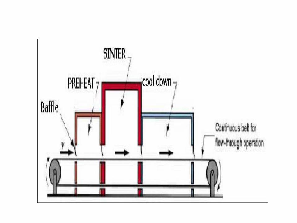
Sintering
➢Sintering is the Heat treatment process, to bond the metallic particles, thereby increasing strength and hardness
➢Sintering consists of heating pressed metal compacts in batch or continuous furnaces to a temperature below the melting point of material.
➢Most metals are sintered at 70% to 80% of melting temperature

A number of secondary and finishing operations can be applied
after sintering, some of them are: Sizing: cold pressing the sintered part to improve
dimensional accuracy. Coining: cold pressing to press details into its
surface . Impregnation: oil fills the pores of the part Infiltration: pores are filled with a molten metal Heat treating: annealing can be done for stress
relief in powder metallurgy part. Machining - creates geometric features that
cannot be achieved by pressing, such as threads, side holes, and other details

Part - II
Non-destructive Testing

Introduction Nondestructive testing (NDT) is a wide group of
analysis techniques used in science and industry to evaluate the properties of a material, component or system without causing damage. Because NDT does not permanently alter the article being inspected, it is a highly-valuable technique that can save both money and time in product evaluation, troubleshooting, and research. Common NDT methods include ultrasonic, magnetic-particle, liquid penetrant, radiographic, and eddy-current testing. NDT is a commonly-used tool in forensic engineering, mechanical engineering, electrical engineering, civil engineering, systems engineering, aeronautical engineering, medicine, and art.

Importance of NDT • Non Destructive Testing, also termed NDT, is
the cornerstone of all activities in all engineering industries.
• Imagine cracked bridges about to break with the effect of excessive weight of vehicles and pedestrians or just say corroded railway tracks making it dangerous for trains to pass or just imagine your vehicle breaking down very often no matter what the brand is.
• Well, perfection and the no-risk factor including flawless performance is the result of non destructive testing.

• This justifies the importance of non destructive testing equipment and universal testing machines to monitor beforehand or during service period the performance features engineering products and services.
• Solid objects may have the risk of breaking in service, no matter whether they carry the guarantee tag, unless they are subjected to non destructive testing during the manufacture stage as well as during use.

• If a welding company utilizes the best welding machines to manufacture casted products, it cannot guarantee of 100% perfect welds. It is mandatory that the products undergo non destructive testing.
• Availability of porous bubbles inside a weld that may cause breakage or rupture, especially in pipes and structures.
• Detection of damage in industrial components during service life.
• Cracks in aircraft skins

Stress corrosion cracking in underground pipelines.
Erosion and corrosion of pipes in industrial plants.
Corrosion of inner reinforcing steel in reinforced concrete structures.
Cracks in welds in pressure vessels.
Broken wires and other damage in wire ropes in suspension bridges.
Missing pieces in assembled finished machined parts.
Improper level of oil in a roller motor and like machines.
Presence of cracks in wheels of locomotives.
• Hence, the importance of non destructive testing. In the category of non destructive testing equipment and universal testing machines, there is also the use of X-rays for non destructive testing, especially for detecting defects in low density materials.
• The scope of non destructive testing and the usage of non destructive testing equipment and universal testing machines applies in various sectors ranging from automotive, aviation, aerospace, construction, maintenance, manufacturing, and more.

Methods of NDT
1.Radiography (X-ray and gamma
ray Test)
2.Ultrasonic Inspection
3.Dye Penetrant Test
4.Magnetic Particle Test
Radiographic Testing • Radiographic Testing is a nondestructive testing (NDT) method of
inspecting materials for hidden flaws by using the ability of short wavelength electromagnetic radiation (high energy photons) to penetrate various materials.
• Either an X-ray machine or a radioactive source can be used as a source of photons. Neutron radiographic testing (NR) is a variant of radiographic testing which uses neutrons instead of photons to penetrate materials. This can see very different things from X-rays, because neutrons can pass with ease through lead and steel but are stopped by plastics, water and oils.
• Since the amount of radiation emerging from the opposite side of the material can be detected and measured, variations in this amount of radiation are used to determine thickness or composition of material. Penetrating radiations are those restricted to that part of the electromagnetic spectrum of wavelength less than about 10 nanometers

X-Ray Radiography Procedure • This technique involves the use of penetrating X-radiation to examine parts
and products for imperfections.
• An X-ray machine or radioactive isotope is used as a source of radiation.
• Radiation is directed through a part and onto film or other media.
• The resulting shadowgraph shows the internal soundness of the part.
• Possible imperfections are indicated as density changes in the film in the
same manner as an X-ray shows broken bones.
• Radiographic applications fall into two distinct categories evaluation of
material properties and evaluation of manufacturing and assembly
properties.
• Material property evaluation includes the determination of composition,
density, uniformity, and cell or particle size. Manufacturing and assembly
property evaluation is normally concerned with dimensions, flaws (voids,
inclusions, and cracks), bond integrity (welds, brazes, etc.), and verification
of proper assembly of component pieces.


Advantages
1. A permanent record of defects in a welded object is obtained.
2. Reference standards for defects are available.
Disadvantages
1. The equipment is costly.
2. Trained operator is required.
3. The method involves radiation hazards.
Applications 1. Pressure vessels and boilers. 2. Penstocks. 3. Aircraft and ship structures.

Gamma-Ray Radiography Gamma-ray radiography differs from X-ray
radiography in following respects:
1. Gamma-rays are used for detecting defects in welded plates thicker than those inspected by X-rays.
2. Owing to less scatter, gamma rays are more satisfactory than X-rays for examining objects of varying thickness, where as X-rays provide better results for welded plates of uniform thickness.
3. X-rays are better than gamma-rays for detecting small defects in Weld element sections less than about 50 mm.
4. X-ray method is much more rapid than gamma-ray method, because unlike gamma-ray method, it requires seconds or minutes instead of hours.

5. Unlike X-ray method, gamma-ray technique can inspect a number of welded objects at one time.
6. Gamma-ray equipment being small possesses better portability and convenience of use for certain field inspections.
7. Gamma radiations, a product of radioactive decay, are extensively used in the testing of welded objects.
8. Radium and its salts decompose at a constant rate, giving out gamma rays which are of much shorter wavelength and more penetrating (than ordinary X-rays).
9. Radium and Radon were originally employed as gamma-ray sources but more convenient sources are available at present in the form of isotopes, for example cobalt 60. It is an isotope produced by neutron irradiation and can be used in place of radium; it is much cheaper as well.

Ultrasonic Crack Detection Introduction (i) Ultrasonic inspection is employed to detect and locate
internal defects such as cracks, porosity, inclusions, lack of fusion and incomplete penetration. Wall thickness can be measured in close vessels or in cases where such measurement cannot otherwise be made.
(ii) Ultrasonic vibrations can be used to locate defects in ferrous and non-ferrous metallic objects as well as in plastics and ceramics.
(iii) Ultrasonic inspection for flaw detection makes use of acoustic waves with frequencies in the range between 20 kHz and 20 MHz, which can be transmitted through solids (even liquid and air as well) and get reflected by the subsurface defects. Ultrasonic waves form a basis for detection, location and size estimation of defects.

Principle of Operation Ultrasonic waves are usually generated by the
Piezoelectric effect which converts electrical energy to mechanical energy.
A quartz crystal is used for the purpose. When a high frequency alternating electric current (of about 1 million cycles per second) is impressed across the faces of the quartz crystal, the crystal will expand during the first half of the cycle and contract when the electric field is reversed.
In this manner the mechanical vibrations (sound waves) arc produced in the crystal.
The surface of job to be inspected by ultrasonic is made fairly smooth either by machining or otherwise so that ultrasonic waves can be efficiently transmitted from the probe into the job and even small defects can be detected properly.
• Ultrasonic inspection employs separate probes (or search units), one for transmitting the waves and other to receive them after passage through the welded jobs.
• Alternatively, since the ultrasonic waves are transmitted as a series of intermittent pulses, the same crystals may be employed both as the transmitter and receiver.
• Before transmitting ultrasonic waves, an oil film is provided between the probe and the job surface; this ensures proper contact between them and better transmission of waves from the probe into the surface of the object to be tested.

• For operation, ultrasonic wave is introduced into the metal and the time interval between transmission of the outgoing and reception of the incoming signals is measured with a cathode ray oscilloscope (CRO).
• The time base of CRO is so adjusted that the full width of the trace represents the section being examined.
• To start with, as the wave is sent from the transmitter probe, it strikes the upper surface of the job and makes a sharp (peak) or pips (echo) at the left hand side of the CRO screen.
If the job is sound, this wave will strike the bottom surface of the same, get reflected and indicated by a pip towards the right-hand end of CRO screen. In case a defect exists in between the top and bottom surfaces, most of the beam striking this defect will get reflected from the defect, reach the receiver probe and indicate a pip (echo) on the CRO screen before the pip given by the waves striking the far end of the job and returning.
The distance of the defect from the surface where transmitter probe is applied, can be determined with the help of a time distance scale in the form of a square wave constantly shown on the oscilloscope. The distance scale may be changed as per convenience and one cycle of square wave may indicate 1 cm or 25cms,etc.
Advantages
1. It is a fast and reliable method of non-destructive inspection.
2. This method of locating flaws with metal objects is more sensitive than radiography.
3. The minimum flaw size which can be detected is equal to about 0.1 % of the distance from the probe to the defect.
4. Big weldments can be systematically scanned for initial detection of major defects.
5. Ultrasonic inspection involves low cost and high speed of operation.
6. The sensitivity of ultrasonic flaw detection is extremely high, being at a maximum when using waves of highest frequency.

Limitations
1. Surface to be tested must be ground smooth and clean.
2. Skilled and trained operator is required.
3. It is not suited to the examination of weld elements of complex shape or configurations.

Applications
1. Inspection of large weld elements, castings and forging, for internal soundness, before carrying out expensive machining operations.
2. Inspection of moving strip or plate (for laminations) as regards its thickness.
3. Routine inspection of locomotive axles and wheel pins for fatigue cracks.
4. Inspection of rails for bolt-hole breaks without dismantling rail-end assemblies.

Liquid dye Penetrant Test • Dye penetrant inspection (DPI), also called liquid
penetrant inspection (LPI) or penetrant testing (PT), is a widely applied and low-cost inspection method used to locate surface-breaking defects in all non-porous materials (metals, plastics, or ceramics).
• The penetrant may be applied to all non-ferrous materials and ferrous materials, but for inspection of ferrous components magnetic-particle inspection is also preferred for its subsurface detection capability.
• LPI is used to detect casting, forging and welding surface defects such as cracks, surface porosities, and leaks in new products, and fatigue cracks on in-service components.

Inspection steps 1. Pre-cleaning:
The test surface is cleaned to remove any dirt, paint, oil, grease or any loose scale that could either keep penetrant out of a defect, or cause irrelevant or false indications.
Cleaning methods may include solvents, alkaline cleaning steps, vapor degreasing, or media blasting.
The end goal of this step is a clean surface where any defects present are open to the surface, dry, and free of contamination.
Note that if media blasting is used, it may "work over" small discontinuities in the part, and an etching bath is recommended as a post-bath treatment.

2. Application of Penetrant:
• The penetrant is then applied to the surface of the item being tested.
• The penetrant is allowed time to soak into any flaws (generally 5 to 30 minutes) is called dwell time.
• The dwell time mainly depends upon the penetrant being used, material being testing and the size of flaws sought.
• As expected, smaller flaws require a longer penetration time.
• Due to their incompatible nature one must be careful not to apply solvent-based penetrant to a surface which is to be inspected with a water-washable penetrant.

3. Excess Penetrant Removal: The excess penetrant is then removed from the surface. The removal method is controlled by the type of
penetrant used. Water-washable, solvent-removable, lipophilic post-emulsifiable, or hydrophilic post-emulsifiable are the common choices.
Emulsifiers represent the highest sensitivity level, and chemically interact with the oily penetrant to make it removable with a water spray.
When using solvent remover and lint-free cloth it is important to not spray the solvent on the test surface directly, because this can remove the penetrant from the flaws.
If excess penetrant is not properly removed, once the developer is applied, it may leave a background in the developed area that can mask indications or defects.
In addition, this may also produce false indications severely hindering your ability to do a proper inspection.

4. Application of Developer: After excess penetrant has been removed a white
developer is applied to the sample. Several developer types are available, including: non-aqueous wet developer, dry powder, water suspendable, and water soluble.
Choice of developer is governed by penetrant compatibility (one can't use water-soluble or suspendable developer with water-washable penetrant), and by inspection conditions.
When using non-aqueous wet developer (NAWD) or dry powder, the sample must be dried prior to application, while soluble and suspendable developers are applied with the part still wet from the previous step.
NAWD is commercially available in aerosol spray cans, and may employ acetone, isopropyl alcohol, or a propellant that is a combination of the two. Developer should form a semi-transparent, even coating on the surface.

• The developer draws penetrant from defects out onto the surface to form a visible indication, commonly known as bleed-out. Any areas that bleed-out can indicate the location, orientation and possible types of defects on the surface. Interpreting the results and characterizing defects from the indications found may require some training and/or experience [the indication size is not the actual size of the defect]
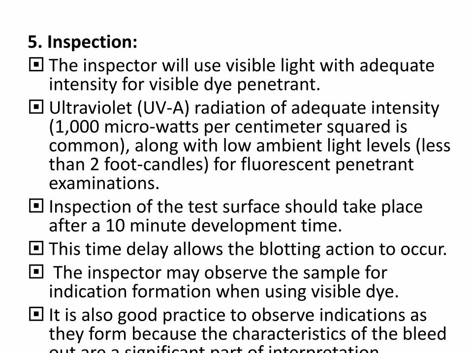
5. Inspection: The inspector will use visible light with adequate
intensity for visible dye penetrant. Ultraviolet (UV-A) radiation of adequate intensity
(1,000 micro-watts per centimeter squared is common), along with low ambient light levels (less than 2 foot-candles) for fluorescent penetrant examinations.
Inspection of the test surface should take place after a 10 minute development time.
This time delay allows the blotting action to occur. The inspector may observe the sample for
indication formation when using visible dye. It is also good practice to observe indications as
they form because the characteristics of the bleed out are a significant part of interpretation characterization of flaws
6. Post Cleaning:
• The test surface is often cleaned after inspection and recording of defects, especially if post-inspection coating processes are scheduled.

Advantages and disadvantages The main advantages of DPI are the speed of the
test and the low cost. The main disadvantages are that it only detects surface flaws and it does not work on very rough surfaces. Also, on certain surfaces a great enough color contrast cannot be achieved or the dye will stain the workpiece.
Limited training is required for the operator — although experience is quite valuable. Proper cleaning is necessary to assure that surface contaminants have been removed and any defects present are clean and dry. Some cleaning methods have been shown to be detrimental to test sensitivity, so acid etching to remove metal smearing and re-open the defect may be necessary

Magnaflux Test
Introduction –
• This method of NDT tends to supplement rather than displace radiography.
• For Example, radiography ordinarily cannot detect small cracks, especially when they are too small to be seen with the human eye.
• Magnetic particles inspection is a relatively simple and easy technique.
• It is almost free from any restriction as to size, shape, composition and treatment of a ferromagnetic specimen.

Principle of this method • When a piece of metal is placed in a magnetic
field and the lines of magnetic flux get inserted by a discontinuity such as crack or slag inclusion in a casting, magnetic poles are induced on either side of the discontinuity.
• The discontinuity causes an abrupt change in the path of magnetic flux flowing through the casting normal to the discontinuity, resulting a local flux leakage field and interference with the magnetic lines of force.

This local flux disturbance can be detected by its affect upon magnetic particles which collect on the region of discontinuity and pile up and bridge over the discontinuity.
A surface crack is indicated by a line of fine particles following the crack outline and a subsurface defect by a fuzzy collection of the magnetic particles on the surface near the discontinuity.
Maximum sensitivity of indication is obtained when the discontinuity lies in a direction normal to the applied magnetic field and when the strength of magnetic field is just enough to saturate the section being inspected.

Techniques Or Procedures
1)Magnetizing the component part
(e.g. casting).
2)Applying magnetic particles on
the component part.
3)Locating the defects.
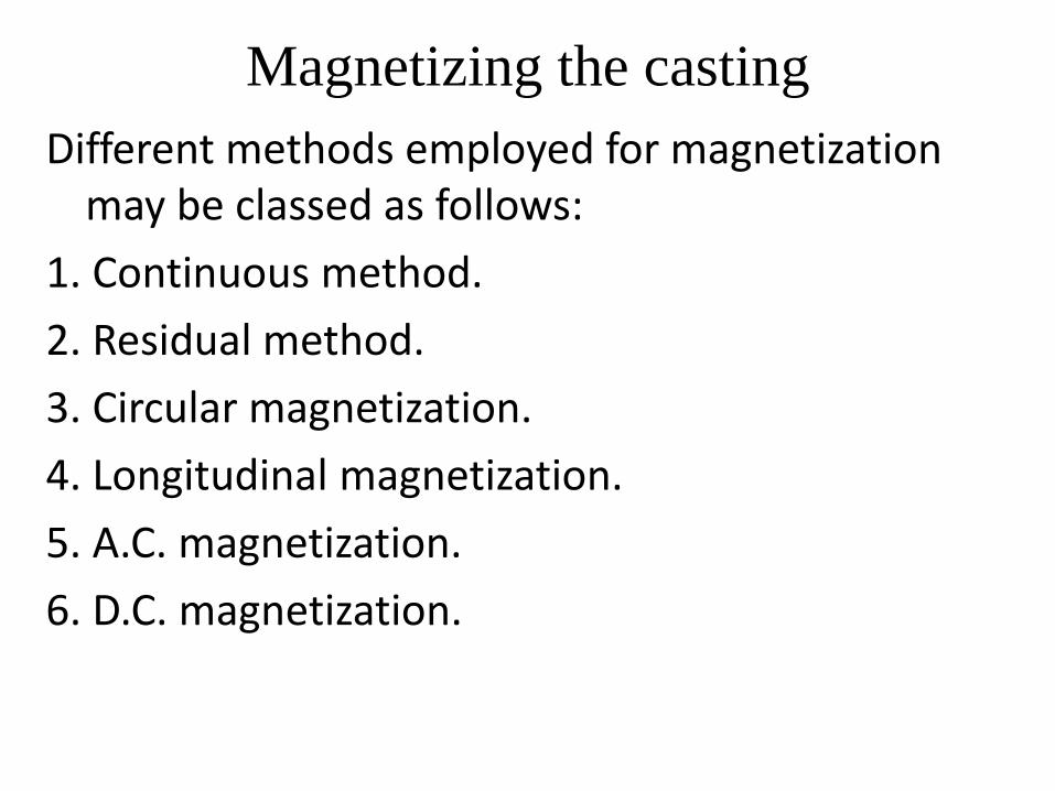
Magnetizing the casting
Different methods employed for magnetization may be classed as follows:
1. Continuous method.
2. Residual method.
3. Circular magnetization.
4. Longitudinal magnetization.
5. A.C. magnetization.
6. D.C. magnetization.

• In continuous method, the current inducing the magnetic flux in the work piece to be inspected is allowed to flow while the powder is applied. The job is placed between two contacts (in the form) of solid copper clamps.
• The induced magnetic field runs in the transverse direction; producing conditions favorable to the detection of longitudinally disposed cracks.
• Continuous method is much mare sensitive than the residual method and especially far steels having law magnetic retentivity, only continuous method is used.

• Residual method relies upon the residual magnetism in the welded job.
• The job may be magnetized by any method but the magnetizing source is removed first and then the magnetic particles are applied over the job.
• Circular magnetization is produced by circular fields.
• A conductor carrying an electric current is surrounded by a magnetic field which farms closed circles in plane at right angles to the direction of current flow.

Circular magnetization may be produced:
(i) By passing current through the part itself.
(ii) By passing current through a conductor placed axially inside the hollow abject.
(iii) With the help of prods or cant acts.
Longitudinal magnetization is produced by passing
current through a solenoid coil .or several turns of
conductor surrounding the jab, the jab serving as
the core of the solenoid. Cable wrappings are
commonly used an large objects such as tanks,
bailers, large crankshafts, etc.
The cracks running in the transverse direction are best revealed in longitudinal fields.

• A.C. magnetization is preferred far maximum surface sensitivity and offers special operating advantages, including straight forward demagnetization after testing, whereas D.C. appears to permit the detection of defects lying mare deeply in the objects.

Applying Magnetic particles or Powder
• Magnetic particles may be applied during the passage of magnetizing current or following the same when the residual magnetism is made use of in detecting cracks in welded objects; this method avoids the danger of over saturation.
• The magnetic powder of iron or black magnetic iron oxide base and having elongated individual particles is used far the purpose Metallic iron particles are coated to prevent oxidation and sticking.
• The powder is available in two colors red and black; a color which shows up to best advantage an the part to be inspected is selected.

• Magnetic particles prepared with a fluorescent coating and inspected under ultraviolet light are also used. In this case the cracks are marked by glowing indication.
• Ordinary magnetic powder is applied the job in Dry or Wet farm.
• Dry powder is applied in form of a cloud or spray. The dry powder is better far locating near surface defects; moreover all the powder can be recovered after the test. Dry powder is not so messy to work with as is the powder wet in oil.

• In wet method, the powder is suspended in law viscosity non-corrosive fluid such as kerosene and is sprayed aver the job; alternatively jab may be immersed in the liquid far the purpose.
• Wet method is better far locating minute surface defects; moreover wetted powder can be applied bath an vertical and underside of horizontal surfaces far detecting cracks.

Applications
This method of inspection is used on magnetic ferrous castings for detecting invisible surface or slightly subsurface defects.
Deeper subsurface defects are not satisfactorily detected because the influence of the distorted lines of magnetic flux (owing to a discontinuity) on the magnetic particles spread over the job surface becomes weaker with the distance, so that sensitivity falls away rapidly with the depth.
The defects commonly revealed by magnetic particle inspection are quenching cracks, thermal cracks, seams, laps, grinding cracks, overlaps, non-metallic inclusions, fatigue cracks, hot tears, etc.
Magnetic particle inspection is a relatively simple and easy technique.
It is almost free from any restriction as to size, shape, composition and heat-treatment of a ferromagnetic specimen.
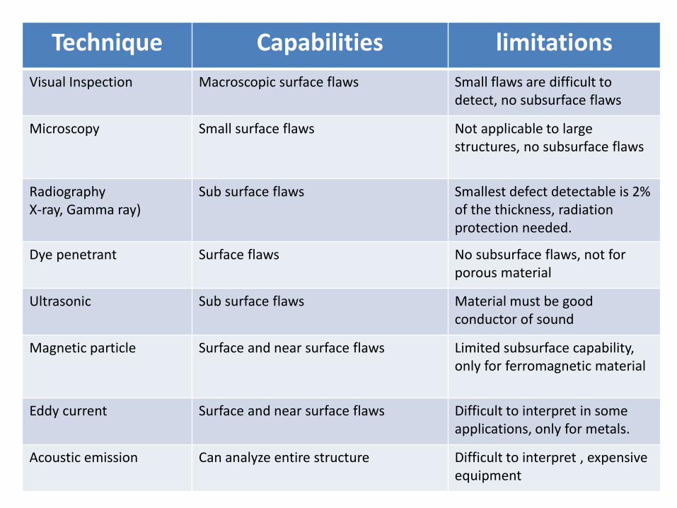
Comparison of various NDT Technique Capabilities limitations
Visual Inspection Macroscopic surface flaws Small flaws are difficult to detect, no subsurface flaws
Microscopy Small surface flaws Not applicable to large structures, no subsurface flaws
Radiography X-ray, Gamma ray)
Sub surface flaws Smallest defect detectable is 2% of the thickness, radiation protection needed.
Dye penetrant Surface flaws No subsurface flaws, not for porous material
Ultrasonic Sub surface flaws
Material must be good conductor of sound
Magnetic particle Surface and near surface flaws Limited subsurface capability, only for ferromagnetic material
Eddy current Surface and near surface flaws
Difficult to interpret in some applications, only for metals.
Acoustic emission Can analyze entire structure Difficult to interpret , expensive equipment
