powder metal steel gears versus wrought steel gears ... · pdf fileperformance tested for...
TRANSCRIPT

1
Powder Metal Steel Gears versus Wrought Steel Gears: Performance Tested for Industrial Applications
Catherine M. Price [email protected]
ACKNOWLEDGEMENTS
Diran Apelian, WPI Professor and Dir, Metal Processing Institute
Tim Geiman, R&D Director for GKN Sinter Metals
GKN Sinter Metals, Germantown, WI
1 INTRODUCTION/BACKGROUND RESEARCH
1.1 Basic Stresses on a Spur Gear Tooth A gear tooth running under industrial loadings will experience three applied stresses: bending
stress, Hertzian stress, and surface contact stress. In turn, these three applied loads will ultimately result in their respective cause of failure, which are as follows: cracks (or tooth shearing), subsurface cracks, and pitting. The stress applied to a spur gear’s tooth during meshing begins with the initial contact of the opposing gear’s tooth. This load results in a tensile stress at the tooth’s root radius in direct contact with the opposing gear tooth, while the root radius of the non-loaded side of the tooth in mesh experiences a compressive stress. As the teeth in mesh move across one another a Hertzian stress and surface contact stress are induced, which forms a rolling-sliding action across the tooth’s surface. Once the opposing tooth moves along the pitch line, pure-rolling stresses initiate. When the tooth moves above the pitch line the Hertzian and surface contact stresses are once again applied to the loaded tooth, though the rolling-sliding action will now be in the reverse direction. This concept can be further understood through Figure 1-1 below. It should be noted that if the two surfaces in contact are properly lubricated there should be no problems during the rolling-sliding actions on the teeth as far as wear failure (Alban, 7.) Also, if the gearsets are properly designed, a tooth in normal service should never fracture but must be expected to eventually fail through wear over time (Norton, 713.)
Figure 1-1: Common Tooth Areas Affected by High Stress Concentration

2
Applied Stress
Pure Rolling Roll-slide Tensile/Compression
Effected Area
Pitch line Addendum/ Dedendum
Opposing root radii
Failure Rolling groove Adhesion, abrasion and/or
pitting Cracks
Table 1-1: Common Stresses Applied to a Gear Tooth and Their Caused Failures
2 TESTING GEAR PERFORMANCE
2.1 Forschungstelle für Zahnräder und Getriebebau (FZG) Visual Method Test As mentioned in the previous section on gear stresses, a gear experiences more than just Hertzian
stresses or RCF. Thus using this method as a test would not properly simulate a meshed gearset during normal industrial application use. Therefore, a back-to-back (or foursquare) test method has been standardized and is referred to as the FZG Visual Method test. It should be noted that this standard uses an FZG test rig, which is described in detail in DIN 51 354. This test rig has been designed specifically for this standard test and therefore, a back-to-back (or foursquare) designed test rig should not be supplemented in its place. Also, the FZG test specifies a standard gearset to be utilized as test specimens, however, as long as the test gear’s fit the FZG test rig’s pre-determined dimensions, then these standard gearsets are not a requirement for testing; especially if there is reason to be testing a specific profile, etc.
The FZG test, as expressed in ASTM D5182-97, is used to determine the scuffing and/or scoring on hardened steel gears due to the oil used for lubrication. The rig itself as mentioned above was specifically designed for this ASTM test procedure, in order to handle the loads and provide proper results. The test rig described in a general sense utilizes a foursquare configuration, which allows for a fixed torque load to be applied to the test gears, shown in Figure 2-1.
Figure 2-1: ASTM D5182-97 FZG Test Rig
Both the driver-side and test-side gearboxes are connected by means of two torsional shafts; the test pinion shaft side contains a load coupling that allows for the applied torque to be induced. The test rig is
3
driven be an electric motor delivering at least 5.5kW (7.4HP) of power and rotating at 1440rpm (ASTM D5182-97.) It should be noted for correct results the test gears need to be properly aligned on their respective shafts. The ASTM D5182-97 describes the testing procedure as follows:
Prior to starting a test apply Load Stage 12 to the system for 2 to 3 minutes without running the motor. This ensures all clearances are in the correct working position. Load the clutch-locking pin in place, and load clutch bolts loose, apply Load Stage 1 to the loading clutch. Tighten the bolts of the load clutch, remove the weight assembly and lever arm, and remove the load clutch-arresting bolt. Start the motor at 1450rpm, run for 21700revs, and then stop the motor. Repeat. At the end of Load Stage 4 record the type of failure and amount of damage observed on the gear flank. The failure criteria is reached when the summed total width of scuffing or scoring damage from all the teeth is estimated to equal or exceed one gear tooth width. This is then reported as the failure load stage.
3 PROBLEM STATEMENT The GKN facility in Germantown, Wisconsin designed and built a gear test machine. The
machine is ultimately configured as a foursquare test rig and was designed to be similar to the FZG test rig discussed above in Chapter 2: Testing Gear Performance. The gears tested followed the ASTM standard D5182-97, also discussed in Chapter 2 and again in Chapter 4: Experimental Procedures. A similar test stand used to evaluate coatings of gears can be found in Gear Technology magazine: Influence of Coatings and Surface Improvements on the Lifetime of Gears, which was used as a guideline and literature review.
The goal of this experiment was to evaluate the performance of various powder metal materials and processes by utilizing the gear machine test bench. The powder metal results gained from the gear test rig were then compared to the performance of wrought materials. The first material used for comparison was wrought 8620-carburized-steel, which is a common gear material. The P/M materials evaluations would include standard PM processing, high density PM processing, rolled tooth flanks, and forged. The experiments also, provided an understanding of the mechanics behind the tests and failures of gears; including induced stresses on gears and dynamics involved in gear testing. This information provided a relation to failure modes, whether rolling contact fatigue caused scuffing or spalling wear. Evaluations included in experimental procedures were microstructures, retained austenite, surface finish, residual stresses, and others that would affect gear performance.
4 RESULTS
4.1 Microstructures The results from the powder metal material’s micro-structural analysis can be seen in Figures 4-1
through 4-4. All of these figures show an etched sample zoomed to 200x and are prior to wear testing.

4
Figure 4-2: HOEG 737 SFH
Figure 4-3: FL4405 HT
4.2 Results from Gear Testing All of the results gained from the GKN foursquare test rig utilized the ASTM standard D5182-97
for testing procedures, thus all of the loads referenced are that associated with the loads table provided in the standard. After optimizing the test rig, the machine was only able to reach an output potential of Load Level 8, therefore all of the gears tested below only reach a maximum applied torque value associated with Load 8. The first gear tested was GKN 815 at maximum density. Figure 4-5 shows the wear on the gear after Load 8. The gear is not officially failed according to the failure criteria expressed in ASTM D5182-97. In Figure 4-5 the dotted line represents the pitch line of the gear and clearly shows a lack of wear in this particular area. The gear’s teeth show signs of polishing and minor scuffing both at the addendum and dedendum of the tooth profile. In Figure 4-10 is the micro-structural image of the gear’s tooth after testing. Figure 4-6 shows the PM material HOEG 737SHF after Load Level 8. This gear is not considered to be failed. There are signs of minor scoring across the entire tooth’s surface, which means the surface is encountering evenly distributed stresses across the surface and thus even wear. The red arrow shows a shinier area, which seems to be the beginnings of moderate wear failure, perhaps even scuffing. In Figure 4-11 is the micro-structural image of the gear’s tooth after testing and also, unetched. The first picture shows what happened to the tooth’s profile after testing; the area circled in red displays a portion of the tooth’s surface that further densified during testing. PM FL-4405HT in Figure 4-7 the photograph shows wear on the tooth’s surface only up to Load Level 7, this is because while running Load Level 8 the gear shattered into several pieces. The gear is not considered to be failed at this point.
Martensite
Austenite
Figure 4-1: GKN 815 SFH
Figure 4-4: Ancorloy 2 Slow Cool
Martensite
Austenite
Pearlite
5
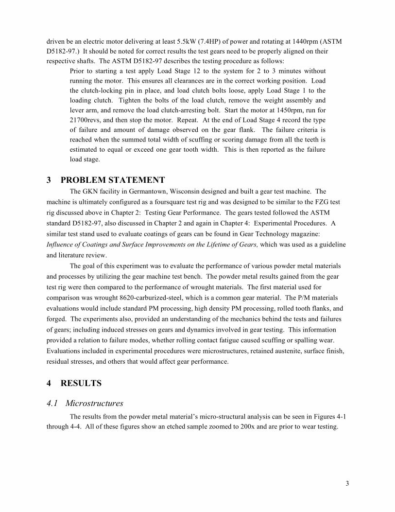
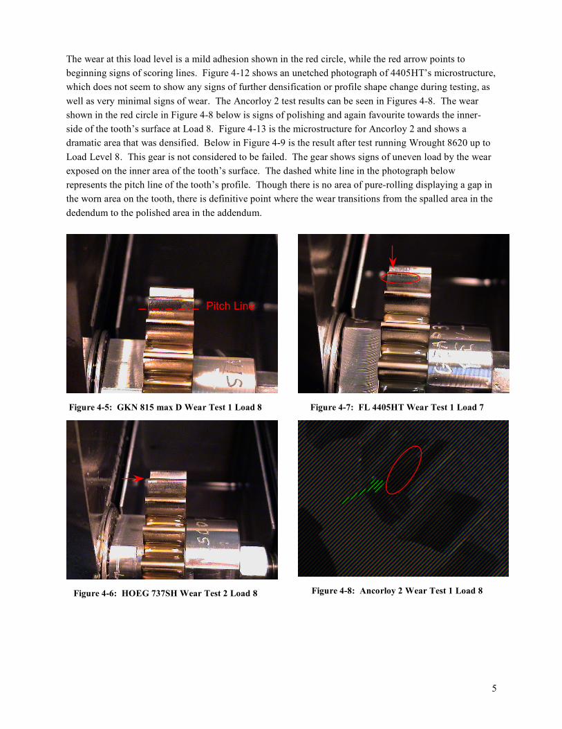
The wear at this load level is a mild adhesion shown in the red circle, while the red arrow points to beginning signs of scoring lines. Figure 4-12 shows an unetched photograph of 4405HT’s microstructure, which does not seem to show any signs of further densification or profile shape change during testing, as well as very minimal signs of wear. The Ancorloy 2 test results can be seen in Figures 4-8. The wear shown in the red circle in Figure 4-8 below is signs of polishing and again favourite towards the inner-side of the tooth’s surface at Load 8. Figure 4-13 is the microstructure for Ancorloy 2 and shows a dramatic area that was densified. Below in Figure 4-9 is the result after test running Wrought 8620 up to Load Level 8. This gear is not considered to be failed. The gear shows signs of uneven load by the wear exposed on the inner area of the tooth’s surface. The dashed white line in the photograph below represents the pitch line of the tooth’s profile. Though there is no area of pure-rolling displaying a gap in the worn area on the tooth, there is definitive point where the wear transitions from the spalled area in the dedendum to the polished area in the addendum.
Figure 4-5: GKN 815 max D Wear Test 1 Load 8
Figure 4-6: HOEG 737SH Wear Test 2 Load 8
Figure 4-7: FL 4405HT Wear Test 1 Load 7
Figure 4-8: Ancorloy 2 Wear Test 1 Load 8
Pitch Line

6
Figure 4-9: Wrought 8620 Wear Test 1 Load 8
Figure 4-10: GKN 815 Worn Tooth at 200x
Figure 4-11: HOEG 737SH Worn Side at 200x
Figure 4-12: FL 4405HT Worn Tooth at 200x
Figure 4-13: Ancorloy Worn Side at 200x
5 CONCLUSIONS In the end the results and conclusions are as follows: gears produced by standard sintering at
maximum density of 7.0g/cc tend to display lower (or at best comparable) wear performance than that of wrought steel. Also, a compensation must be made between wear resistance and hardness when designing gear materials, otherwise a shattered gear or deformed profile may be the end result.