powder feed center - nordsonemanuals.nordson.com/finishing/files/powder/334590a03.pdf · powder...
TRANSCRIPT

Powder Feed Center
Customer Product ManualPart 334590A03
Issued 1/09
NORDSON CORPORATION • AMHERST, OHIO • USA
For parts and technical support, call the Industrial CoatingSystems Customer Support Center at (800) 433-9319 or
contact your local Nordson representative.
This document is subject to change without notice.Check http://emanuals.nordson.com for the latest version.

Part 334590A03 � 2009 Nordson Corporation
Contact UsNordson Corporation welcomes requests for information, comments, andinquiries about its products. General information about Nordson can befound on the Internet using the following address:http://www.nordson.com.Address all correspondence to:
Nordson CorporationAttn: Customer Service555 Jackson StreetAmherst, OH 44001
NoticeThis is a Nordson Corporation publication which is protected by copyright.Original copyright date 2002. No part of this document may bephotocopied, reproduced, or translated to another language without theprior written consent of Nordson Corporation. The information containedin this publication is subject to change without notice.
Trademarks
Nordson and the Nordson logo are registered trademarks of NordsonCorporation.
Tivar is a registered trademark of Poly Hi Solidur, Inc.
Vibrasonic is a trademark of Russell Finex Limited Corporation.

1
Table of ContentsSafety 1-1. . . . . . . . . . . . . . . . . . . . . . . . . . . . . . . . . . . .Introduction 1-1. . . . . . . . . . . . . . . . . . . . . . . . . . . . . . . .Qualified Personnel 1-1. . . . . . . . . . . . . . . . . . . . . . . . .Intended Use 1-1. . . . . . . . . . . . . . . . . . . . . . . . . . . . . .Regulations and Approvals 1-1. . . . . . . . . . . . . . . . . .Personal Safety 1-2. . . . . . . . . . . . . . . . . . . . . . . . . . . .Fire Safety 1-2. . . . . . . . . . . . . . . . . . . . . . . . . . . . . . . . .Grounding 1-3. . . . . . . . . . . . . . . . . . . . . . . . . . . . . . . . .Action in the Event of a Malfunction 1-4. . . . . . . . . . .Disposal 1-4. . . . . . . . . . . . . . . . . . . . . . . . . . . . . . . . . .
Description 2-1. . . . . . . . . . . . . . . . . . . . . . . . . . . . . . .Introduction 2-1. . . . . . . . . . . . . . . . . . . . . . . . . . . . . . . .Components 2-2. . . . . . . . . . . . . . . . . . . . . . . . . . . . . . .Operator Interface 2-4. . . . . . . . . . . . . . . . . . . . . . . . . .Theory of Operation 2-4. . . . . . . . . . . . . . . . . . . . . . . . .
Powder Fluidization and Transfer 2-4. . . . . . . . . . .Air Filtration 2-6. . . . . . . . . . . . . . . . . . . . . . . . . . . . .Purge Cycle 2-7. . . . . . . . . . . . . . . . . . . . . . . . . . . . .Sure Max Powder Transfer System Operation 2-7
Normal Operation 2-8. . . . . . . . . . . . . . . . . . . . .Color Change Operation 2-9. . . . . . . . . . . . . . .
Initial Setup 3-1. . . . . . . . . . . . . . . . . . . . . . . . . . . . . . .Introduction 3-1. . . . . . . . . . . . . . . . . . . . . . . . . . . . . . .User Access Levels 3-2. . . . . . . . . . . . . . . . . . . . . . . .Feed Center Configuration Menu 3-2. . . . . . . . . . . . .Spray System Configuration Menu 3-4. . . . . . . . . . . .Typical Operating Settings 3-6. . . . . . . . . . . . . . . . . . .
Operating Air Pressures 3-6. . . . . . . . . . . . . . . . . .Cartridge Filter Pulse Valve Timing Settings 3-6. .
Level Sensor Programming 3-7. . . . . . . . . . . . . . . . . .Operation 3-7. . . . . . . . . . . . . . . . . . . . . . . . . . . . . .
One Button Level Sensor Probe Programming 3-8. . . . . . . . . . . . . . . . . . . . . . .Operational Faults (Red LED Flashing) 3-10. .Locking and Unlocking Adjustment 3-10. . . . . .
Two Button Level Sensor Probe Programming 3-11LED Functions for Operation 3-11. . . . . . . . . . .Empty (no powder) Adjustment 3-12. . . . . . . . .Full Adjustment 3-12. . . . . . . . . . . . . . . . . . . . . . .Locking and Unlocking Adjustment 3-13. . . . . .Operational Faults 3-13. . . . . . . . . . . . . . . . . . . .
Operation 4-1. . . . . . . . . . . . . . . . . . . . . . . . . . . . . . . . .Introduction 4-1. . . . . . . . . . . . . . . . . . . . . . . . . . . . . . . .Operator Interface Menus 4-2. . . . . . . . . . . . . . . . . . .
Main Menu 4-2. . . . . . . . . . . . . . . . . . . . . . . . . . . . .Auto Menu 4-3. . . . . . . . . . . . . . . . . . . . . . . . . . . . .Manual Functions 4-5. . . . . . . . . . . . . . . . . . . . . . . .Setup and Special Functions 4-5. . . . . . . . . . . . . .
Daily Startup 4-6. . . . . . . . . . . . . . . . . . . . . . . . . . . . . .Powder Feed Source Installation 4-7. . . . . . . . . . . . . .
Powder Box Installation 4-7. . . . . . . . . . . . . . . . . . .Fluidizing Hopper Installation 4-8. . . . . . . . . . . . . .
Shutdown 4-9. . . . . . . . . . . . . . . . . . . . . . . . . . . . . . . . .
2
Color Change 5-1. . . . . . . . . . . . . . . . . . . . . . . . . . . . .Introduction 5-1. . . . . . . . . . . . . . . . . . . . . . . . . . . . . . . .
Types of Color Changes 5-1. . . . . . . . . . . . . . . . . .Performing a Color Change 5-3. . . . . . . . . . . . . . . .
Color Change Control Menu 5-3. . . . . . . . . . . . . . . . . .Menu Navigation 5-4. . . . . . . . . . . . . . . . . . . . . . . . .Color Change Menu Functions 5-5. . . . . . . . . . . . .
Quick Color Change System Color Change Process . . . . .5-6
Changing the Sure Max Filter Element 5-12. . . . . .Removal 5-12. . . . . . . . . . . . . . . . . . . . . . . . . . . . .Installation 5-12. . . . . . . . . . . . . . . . . . . . . . . . . . .
Washing the Sure Max Filter Element 5-14. . . . . .Conventional System Color Change Process 5-15. . .
Maintenance 6-1. . . . . . . . . . . . . . . . . . . . . . . . . . . . . .Daily Maintenance 6-1. . . . . . . . . . . . . . . . . . . . . . . . . .Emptying the Waste Hopper 6-2. . . . . . . . . . . . . . . . . .Periodic Maintenance 6-4. . . . . . . . . . . . . . . . . . . . . . .
Troubleshooting 7-1. . . . . . . . . . . . . . . . . . . . . . . . . . .Powder Supply Problems 7-2. . . . . . . . . . . . . . . . . . .Purge Cycle Problems 7-4. . . . . . . . . . . . . . . . . . . . . .
Bottom of Stroke Sensor and Stop Bolt Realignment . . . . . .7-4
Sieve Problems 7-6. . . . . . . . . . . . . . . . . . . . . . . . . . . .Filter Section Problems 7-7. . . . . . . . . . . . . . . . . . . . . .
Repair 8-1. . . . . . . . . . . . . . . . . . . . . . . . . . . . . . . . . . . .Introduction 8-1. . . . . . . . . . . . . . . . . . . . . . . . . . . . . . . .Cartridge Filter Replacement 8-1. . . . . . . . . . . . . . . . .
Removing the Cartridge Filter 8-2. . . . . . . . . . . . . .Installing the Cartridge Filter 8-2. . . . . . . . . . . . . . .
Final Filter Replacement 8-4. . . . . . . . . . . . . . . . . . . . .Pulse Valve Replacement 8-5. . . . . . . . . . . . . . . . . . . .Waste Hopper Fluidizing Plate Replacement 8-6. . . .Vibratory Table Isolator Mount Replacement 8-7. . .
Parts 9-1. . . . . . . . . . . . . . . . . . . . . . . . . . . . . . . . . . . . .Introduction 9-1. . . . . . . . . . . . . . . . . . . . . . . . . . . . . . .
Using the Illustrated Parts List 9-1. . . . . . . . . . . . .Powder Feed Center Assembly 9-2. . . . . . . . . . . . . . .Sieve Assembly 9-4. . . . . . . . . . . . . . . . . . . . . . . . . . . .Sure Max Powder Transfer System 9-6. . . . . . . . . . . .
Sure Max System Assembly 9-6. . . . . . . . . . . . . . .Sure Max Receiver and Filter 9-8. . . . . . . . . . . . . .Filter Containers 9-8. . . . . . . . . . . . . . . . . . . . . . . . .
Lance Arm Assembly 9-10. . . . . . . . . . . . . . . . . . . . . . .Vibratory Table and Purge Assembly 9-12. . . . . . . . . .Fan Housing Assembly 9-14. . . . . . . . . . . . . . . . . . . . . .Blowdown Housing Assembly 9-15. . . . . . . . . . . . . . . .Cartridge Filter Housing Assembly 9-16. . . . . . . . . . . .Fluid Bed Assembly 9-17. . . . . . . . . . . . . . . . . . . . . . . . .

3
Options 10-1. . . . . . . . . . . . . . . . . . . . . . . . . . . . . . . . . . .Introduction 10-1. . . . . . . . . . . . . . . . . . . . . . . . . . . . . . . .Fluidizing Hopper 10-1. . . . . . . . . . . . . . . . . . . . . . . . . . .
Installation 10-1. . . . . . . . . . . . . . . . . . . . . . . . . . . . . .Fluidizing Plate Replacement 10-4. . . . . . . . . . . . . .Fluidizing Hopper Parts 10-4. . . . . . . . . . . . . . . . . .
Vibrasonic Sieve Screen 10-6. . . . . . . . . . . . . . . . . . . . .Vibrasonic System Components 10-6. . . . . . . . . . .Installation 10-7. . . . . . . . . . . . . . . . . . . . . . . . . . . . . .
Vibrasonic Transducer and Sieve Screen Installation . . . . . .10-7Control Box and Cable Installation 10-7. . . . . . .
Operation 10-8. . . . . . . . . . . . . . . . . . . . . . . . . . . . . . .Troubleshooting 10-8. . . . . . . . . . . . . . . . . . . . . . . . .
Fault Conditions 10-8. . . . . . . . . . . . . . . . . . . . . . .Causes and Corrective Actions 10-9. . . . . . . . . .VIBRASONICS/POWER Indicator Troubleshooting . . . . . . . .10-10
Vibrasonic System Parts 10-11. . . . . . . . . . . . . . . . . .

4

Safety 1-1
Part 334590A03� 2009 Nordson Corporation
Section 1Safety
IntroductionRead and follow these safety instructions. Task- and equipment-specificwarnings, cautions, and instructions are included in equipmentdocumentation where appropriate.
Make sure all equipment documentation, including these instructions, isaccessible to all persons operating or servicing equipment.
Qualified PersonnelEquipment owners are responsible for making sure that Nordson equipmentis installed, operated, and serviced by qualified personnel. Qualifiedpersonnel are those employees or contractors who are trained to safelyperform their assigned tasks. They are familiar with all relevant safety rulesand regulations and are physically capable of performing their assignedtasks.
Intended UseUse of Nordson equipment in ways other than those described in thedocumentation supplied with the equipment may result in injury to personsor damage to property.
Some examples of unintended use of equipment include
� using incompatible materials
� making unauthorized modifications
� removing or bypassing safety guards or interlocks
� using incompatible or damaged parts
� using unapproved auxiliary equipment
� operating equipment in excess of maximum ratings
Regulations and ApprovalsMake sure all equipment is rated and approved for the environment in whichit is used. Any approvals obtained for Nordson equipment will be voided ifinstructions for installation, operation, and service are not followed.

Safety1-2
Part 334590A03 � 2009 Nordson Corporation
All phases of equipment installation must comply with all federal, state, andlocal codes.
Personal SafetyTo prevent injury follow these instructions.
� Do not operate or service equipment unless you are qualified.
� Do not operate equipment unless safety guards, doors, or covers areintact and automatic interlocks are operating properly. Do not bypass ordisarm any safety devices.
� Keep clear of moving equipment. Before adjusting or servicing anymoving equipment, shut off the power supply and wait until theequipment comes to a complete stop. Lock out power and secure theequipment to prevent unexpected movement.
� Relieve (bleed off) hydraulic and pneumatic pressure before adjusting orservicing pressurized systems or components. Disconnect, lock out,and tag switches before servicing electrical equipment.
� Obtain and read Material Safety Data Sheets (MSDS) for all materialsused. Follow the manufacturer’s instructions for safe handling and useof materials, and use recommended personal protection devices.
� To prevent injury, be aware of less-obvious dangers in the workplacethat often cannot be completely eliminated, such as hot surfaces, sharpedges, energized electrical circuits, and moving parts that cannot beenclosed or otherwise guarded for practical reasons.
Fire SafetyTo avoid a fire or explosion, follow these instructions.
� Do not smoke, weld, grind, or use open flames where flammablematerials are being used or stored.
� Provide adequate ventilation to prevent dangerous concentrations ofvolatile materials or vapors. Refer to local codes or your material MSDSfor guidance.
� Do not disconnect live electrical circuits while working with flammablematerials. Shut off power at a disconnect switch first to preventsparking.
Safety 1-3
Part 334590A03� 2009 Nordson Corporation
� Know where emergency stop buttons, shutoff valves, and fireextinguishers are located. If a fire starts in a spray booth, immediatelyshut off the spray system and exhaust fans.
� Clean, maintain, test, and repair equipment according to the instructionsin your equipment documentation.
� Use only replacement parts that are designed for use with originalequipment. Contact your Nordson representative for parts informationand advice.
GroundingWARNING: Operating faulty electrostatic equipment is hazardous and cancause electrocution, fire, or explosion. Make resistance checks part of yourperiodic maintenance program. If you receive even a slight electrical shockor notice static sparking or arcing, shut down all electrical or electrostaticequipment immediately. Do not restart the equipment until the problem hasbeen identified and corrected.
All work conducted inside the spray booth or within 1 m (3 ft) of boothopenings is considered within a Class 2, Division 1 or 2 Hazardous locationand must comply with NFPA 33, NFPA 70 (NEC articles 500, 502, and 516),and NFPA 77, latest conditions.
� All electrically conductive objects in the spray areas shall be electricallyconnected to ground with a resistance of not more than 1 megohm asmeasured with an instrument that applies at least 500 volts to the circuitbeing evaluated.
� Equipment to be grounded includes, but is not limited to, the floor of thespray area, operator platforms, hoppers, photoeye supports, andblow-off nozzles. Personnel working in the spray area must begrounded.
� There is a possible ignition potential from the charged human body.Personnel standing on a painted surface, such as an operator platform,or wearing non-conductive shoes, are not grounded. Personnel mustwear shoes with conductive soles or use a ground strap to maintain aconnection to ground when working with or around electrostaticequipment.
� Operators must maintain skin-to-handle contact between their hand andthe gun handle to prevent shocks while operating manual electrostaticspray guns. If gloves must be worn, cut away the palm or fingers, wearelectrically conductive gloves, or wear a grounding strap connected tothe gun handle or other true earth ground.
� Shut off electrostatic power supplies and ground gun electrodes beforemaking adjustments or cleaning powder spray guns.
� Connect all disconnected equipment, ground cables, and wires afterservicing equipment.

Safety1-4
Part 334590A03 � 2009 Nordson Corporation
Action in the Event of a MalfunctionIf a system or any equipment in a system malfunctions, shut off the systemimmediately and perform the following steps:
� Disconnect and lock out electrical power. Close pneumatic shutoffvalves and relieve pressures.
� Identify the reason for the malfunction and correct it before restarting theequipment.
DisposalDispose of equipment and materials used in operation and servicingaccording to local codes.

Description 2-1
Part 334590A03� 2009 Nordson Corporation
Section 2Description
IntroductionThe Nordson powder feed center delivers powder to up to 27 powder sprayguns, while simultaneously receiving and conditioning reclaimed powderand introducing it back into the virgin powder source. The powder feedcenter efficiently reclaims powder and helps a powder coating systemachieve fast, efficient color changes.
Refer to Table 2-1.
The powder feed center may be used with two types of powder coatingsystems:
Table 2-1 Compatible Powder Coating Systems
System Type Description
Quick Color Change These systems are specially equipped toquickly perform color changes. Quick colorchange systems include the followingNordson product lines:
� Colormax
� Sure Clean
Conventional These systems use conventional cyclone orcartridge technology. Conventional colorchange systems include the followingNordson product lines:
� Cyclo-Kinetic
� Excel
� Horizon
Description2-2
Part 334590A03 � 2009 Nordson Corporation
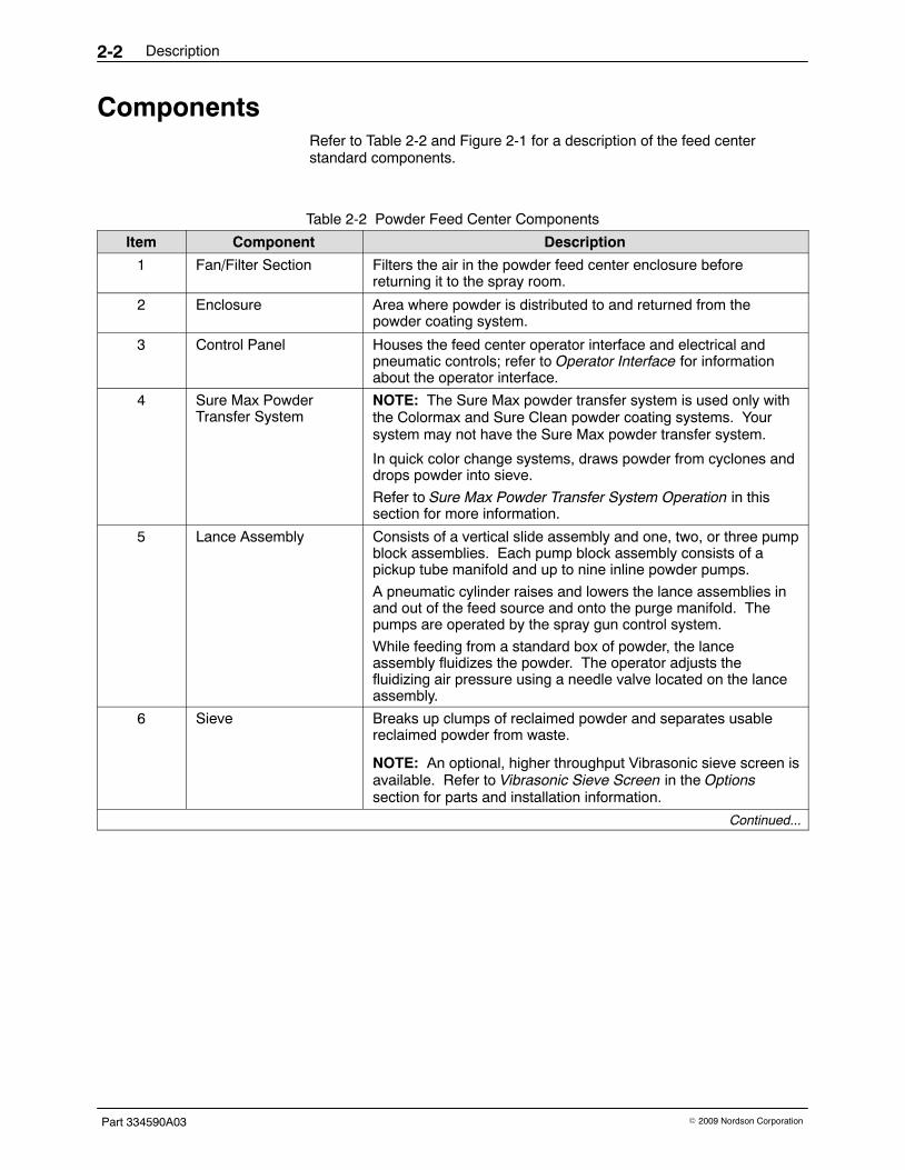
ComponentsRefer to Table 2-2 and Figure 2-1 for a description of the feed centerstandard components.
Table 2-2 Powder Feed Center Components
Item Component Description
1 Fan/Filter Section Filters the air in the powder feed center enclosure beforereturning it to the spray room.
2 Enclosure Area where powder is distributed to and returned from thepowder coating system.
3 Control Panel Houses the feed center operator interface and electrical andpneumatic controls; refer to Operator Interface for informationabout the operator interface.
4 Sure Max PowderTransfer System
NOTE: The Sure Max powder transfer system is used only withthe Colormax and Sure Clean powder coating systems. Yoursystem may not have the Sure Max powder transfer system.
In quick color change systems, draws powder from cyclones anddrops powder into sieve.
Refer to Sure Max Powder Transfer System Operation in thissection for more information.
5 Lance Assembly Consists of a vertical slide assembly and one, two, or three pumpblock assemblies. Each pump block assembly consists of apickup tube manifold and up to nine inline powder pumps.
A pneumatic cylinder raises and lowers the lance assemblies inand out of the feed source and onto the purge manifold. Thepumps are operated by the spray gun control system.
While feeding from a standard box of powder, the lanceassembly fluidizes the powder. The operator adjusts thefluidizing air pressure using a needle valve located on the lanceassembly.
6 Sieve Breaks up clumps of reclaimed powder and separates usablereclaimed powder from waste.
NOTE: An optional, higher throughput Vibrasonic sieve screen isavailable. Refer to Vibrasonic Sieve Screen in the Optionssection for parts and installation information.
Continued...

Description 2-3
Part 334590A03� 2009 Nordson Corporation
DescriptionComponentItem
7 Feed Source Stores the powder supply for the spray guns. The source maybe either a standard box of powder or an optional fluidizinghopper.
NOTE: Optional fluidizing hopper is shown. Refer to theOptions section for more information.
8 Vibratory Table Vibrates to prevent cavitation when feeding powder from astandard box of powder.
NOTE: The vibratory table only vibrates for a short time whilethe optional fluidizing hopper is being used.
9 Purge Manifold Pulses compressed air through the pickup tubes, pumps, powderfeed hoses, and spray guns to blow out all loose powder.Consists of one manifold block for each lance assembly. Eachmanifold block is equipped with up to nine open ports to matchthe number of pumps and spray guns in the system.
3
8
5 4
10 9
3
8
5 4
10 9
2 1
7 6
2 1
7 6 678910
12345
678910
12345
3 5
6
7
89
2
1
4
Figure 2-1 Powder Feed Center Components

Description2-4
Part 334590A03 � 2009 Nordson Corporation
Operator InterfaceThe control panel houses a PLC that controls the powder feed center’soperations. The operator can adjust and start or stop the automatedfunctions using the touch screen operator interface located in the controlpanel. Refer to the Operation section for more information about theoperator interface.
NOTE: In quick color change systems, the PLC and operator interface alsocontrol other booth functions. Refer to your quick color change systemmanual for more information about the operator interface.
Theory of OperationThe following paragraphs explain how the powder feed center operates.
Powder Fluidization and TransferSee Figure 2-2.
A feed source (5) is placed directly on the vibratory table (6). Powder in thefeed source is fluidized and the lance assembly (4) lowers in one of thefollowing ways:
Box of Powder: The vibratory table vibrates to maintain an evendistribution of powder in the box. The lance assembly fluidizes the powderin the box. When all feed center functions are set to AUTO, the lanceassembly lowers until its level sensor senses the powder in the box, andcontinues to lower as the powder level falls. When the level sensor sensesthat the lance assembly has lowered below a set limit, the sensor activateseither a low-powder alarm or automatic bulk feed.
Fluidizing Hopper (Optional): Compressed air forced through a porousfluidizing plate in the bottom of the hopper fluidizes the powder in thehopper. When all feed center functions are set to AUTO, the lanceassembly lowers into the hopper until it reaches a set position. The lanceassembly stays at the set position. When the level sensor senses that thepowder level has fallen below a set limit (above the lance inlet), the sensoractivates either a low-powder alarm or automatic bulk feed.
Air flowing through the powder pumps (3) draws the fluidized powder up thelance assembly and out the powder feed hoses to the spray guns.
Standard powder feed centers have two sets of powder feed hoses: one foruse with light-colored powders, and one for use with dark-colored powders.Having two separate sets of powder feed hoses minimizes the possibility ofcross-contamination of powder after a color change.

Description 2-5
Part 334590A03� 2009 Nordson Corporation
In applications that use special powders (such as metallics or textures), aseparate set of hoses can be added. The feed center can accommodate upto four sets of hoses:
� Standard, light-color powders
� Standard, dark-color powders
� Special, light-color powders
� Special, dark-color powders
When a set of hoses is not being used, it is stored offline in the hose lockeron the side of the feed center.
3
4
6
5
1
2
Figure 2-2 Powder Feed Center Operation
1. Purge manifold2. Sieve3. Powder pumps
4. Lance assembly5. Feed source6. Vibratory table
Note: Optional fluidizing hopper shown.

Description2-6
Part 334590A03 � 2009 Nordson Corporation
Air Filtration See Figure 2-3.
The exhaust fan (1) draws airborne powder through the cartridge filters (4),where the powder collects on the filter media.
The pulse valves (3) send periodic pulses of air through the cartridge filters,blowing the powder off the filter media. The powder then falls into the wastehopper (5), which holds the waste powder until the operator empties it usingthe feed center’s transfer pump.
Any powder that remains in the air that passes through the cartridge filtersis collected on the final filters (2) before the air returns to the spray room.
1
3
4
5
2
3
8
5 4
10 9
3
8
5 4
10 9
2 1
7 6
2 1
7 6 678910
12345
678910
12345
Figure 2-3 Powder Feed Center Air Filtration
1. Exhaust fan2. Final filters3. Pulse valves
4. Cartridge filters5. Waste hopper

Description 2-7
Part 334590A03� 2009 Nordson Corporation
Purge CycleSee Figure 2-2.
The operator starts a purge cycle either when changing colors or shuttingdown the system. When the purge cycle starts, the spray guns turn off andthe lance assembly raises up out of the feed source. The operator blowspowder off the lance assembly, then removes the feed source from thevibratory table.
The operator lowers the lance assembly until the pickup tubes contact thepurge manifold (1). The purge manifold sends timed pulses of air throughthe pickup tubes, powder pumps, powder feed hoses, and spray guns.
NOTE: Depending on how the feed center is configured, the purge cyclepurges each pump block assembly separately, or all pump block assembliesat the same time.
Sure Max Powder Transfer System OperationNOTE: In powder coating systems that do not have the Sure Max powdertransfer system, oversprayed powder collects in either a surge hopper at thebottom of the cyclones or the booth collector module. A transfer pumppumps the powder back to the powder feed center.
Refer to the following paragraphs for the Sure Max powder transfersystem’s process during normal and color change operations.

Description2-8
Part 334590A03 � 2009 Nordson Corporation
Normal OperationSee Figure 2-4.
During normal operation, reclaimed powder collects in the transfer pan (11)at the bottom of the cyclones. The scrap port on the transfer pan is pluggedwith the scrap cap (9), and both reclaim plugs (3) are disconnected. Thevacuum amplifier (1) draws the reclaimed powder out of the transfer panand through the reclaim conveyor line (8). The powder collects in thereclaim receiver (5), which filters the powder from the air before it gets tothe vacuum amplifier.
The reclaim receiver’s discharge door (6) periodically opens, dropping thereclaimed powder into the sieve (7). The sieve separates contaminatesfrom the reclaimed powder before dropping the powder back into the feedsource.
1
2
5
6
7
8
4
1112
Reclaimed Powder
Vacuum
3
4
3 910
Figure 2-4 Sure Max Powder Transfer System: Normal Operation
1. Vacuum amplifier2. Vacuum diverter handle3. Reclaim plug4. Reclaim couplings
5. Reclaim receiver6. Discharge door7. Sieve8. Reclaim conveyor line
9. Scrap cap10. Scrap conveyor line11. Transfer pan12. Scrap receiver

Description 2-9
Part 334590A03� 2009 Nordson Corporation
Color Change Operation See Figure 2-5.
At the beginning of the color change process, the discharge door (6)remains open. Pulses of air are forced through the filter in the reclaimreceiver (5), blowing loose powder off the filter.
At the end of the color change process, the operator disconnects thereclaim couplings (4) attaching the reclaim conveyor line (8); cleans andplugs (3) the reclaim conveyor line; removes the scrap cap (9) and installsthe scrap conveyor line (10). The operator then turns the vacuum diverterhandle (2) counterclockwise to cause oversprayed powder to be drawn outof the transfer pan (11) and into the scrap receiver (12). Spraying 0.5 kg(one lb) of overspray to waste seasons the ducts and cyclones, allowing forefficient powder reclaim during normal operation.
After 0.5 kg (one lb) of overspray has been collected in the scrap receiver,the operator disconnects the scrap conveyor line; installs the scrap cap;uncaps and connects the reclaim conveyor line; and turns the diverterhandle clockwise to return the system to normal operation (reclaim mode).
1
2
5
6
7
8
4
11 12
Reclaimed Powder
Vacuum
3
4 3 910
Figure 2-5 Sure Max Powder Transfer System: Color Change Operation
1. Vacuum amplifier2. Vacuum diverter handle3. Reclaim plug4. Reclaim couplings
5. Reclaim receiver6. Discharge door7. Sieve8. Reclaim conveyor line
9. Scrap cap10. Scrap conveyor line11. Transfer pan12. Scrap receiver

Description2-10
Part 334590A03 � 2009 Nordson Corporation

Initial Setup 3-1
Part 334590A03� 2009 Nordson Corporation
Section 3Initial Setup
WARNING: Allow only qualified personnel to perform the following tasks.Follow the safety instructions in this document and all other relateddocumentation.
Introduction This section explains how to set up the powder feed center to suit yourapplication requirements. The following topics are covered in this section:
Topic Description
User Access Levels Logging in to the feed center’s operator interface using one ofthree access levels
Feed Center Configuration Menu Setting up the operator interface to recognize the optionalhardware that is included with your feed center
Spray System Configuration Menu Setting up the operator interface to recognize the optionalhardware that is included in the powder coating system
Typical Operating Settings Setting the recommended air pressure and cartridge filter pulsetiming values for the feed center
Level Sensor Programming Programming the level sensor probe to cause the lanceassembly to raise or lower to the appropriate level in the powderfeed source
These procedures need to be completed only when you start up the powderfeed center for the first time. After the initial configuration is completed andthe system is operating, you may also access the configuration menus tochange operating parameters.

Initial Setup3-2
Part 334590A03 � 2009 Nordson Corporation
User Access Levels There are three user access levels. Not all users have access to adjust allfunctions of the powder feed center.
The user access level can be changed by touching the Log-On button inthe Special Functions area of the Main Menu or on either of theconfiguration screens. Refer to Table 3-1 for a list of the three user accesslevels and their passwords. The default user access level is Operator.
Table 3-1 User Access Levels
User Access Level Password
Operator 0
Lead Operator 108
Supervisor 1597
Feed Center Configuration Menu See Screen 3-1. The Feed Center Configuration menu appears the firsttime that the powder feed center is powered up. This menu allows you toidentify the components that are used in your powder feed center.
All configuration settings on the menu are YES/NO selections. Touch abutton to change the current selection from NO to YES. Touch the buttonagain to change it back to NO. Refer to Table 3-2 for a description of thebuttons on the menu.
NOTE: To access the Feed Center Configuration menu from the MainMenu, touch the Special Functions button, then the System Configbutton.
Screen 3-1 Feed Center Configuration Menu

Initial Setup 3-3
Part 334590A03� 2009 Nordson Corporation
Table 3-2 Feed Center Configuration Menu
Selection Description Note
Sure CleanSpray System
Select YES if the feed center is used with a Sure Cleansystem
ColormaxSpray System
Select YES if the feed center is used with a Colormaxsystem
Sure Max System Select YES if the feed center is equipped with aSure Max powder transfer system
Gun Purge Valve #1 Select YES if purge valve #1 is used A
Gun Purge Valve #2 Select YES if purge valve #2 is used A
Gun Purge Valve #3 Select YES if purge valve #3 is used A
Sieve Vibrator Select YES if the feed center is equipped with a vibratorysieve motor (feed center does not have a feed chutevibrator)
B
Vibrasonic Sieve Screen Select YES if the feed center is equipped with theVibrasonic sieve screen system
Feed Chute Vibrator Select YES if the feed center is equipped with a feedchute vibrator (feed center does not have a vibratorysieve motor)
B
Four Filter Pulse Valves Select YES if there are four cartridge filters (the standardnumber is three)
Configuration Completed Select YES if the configuration process has beencompleted
� The Spray System Configuration menu will appearwhen you touch this button if either Sure CleanSystem or Colormax System is set to YES
� The Special Functions menu will appear when youtouch this button if either Sure Clean System orColormax System is set to NO
Special Functions Opens the Special Functions menu C
Log-On Allows you to change to a different user access level
Config System Opens the Spray System Configuration menu C
NOTE A: Each gun purge valve can purge up to nine spray guns. Enable the appropriate number of gun purge valves based on how many spray guns are in your system.
B: The powder feed center has either a sieve vibrator motor or a feed chute vibrator.
C: This button is visible only if Configuration Completed is set to YES.

Initial Setup3-4
Part 334590A03 � 2009 Nordson Corporation
Spray System Configuration Menu See Screen 3-2. The Spray System Configuration menu allows you toidentify the components that are used in your powder coating system.
Screen 3-2 Spray System Configuration Menu

Initial Setup 3-5
Part 334590A03� 2009 Nordson Corporation
All configuration buttons on the menu are YES/NO selections. Touch abutton to change the current selection from NO to YES. Touch the buttonagain to change it back to NO. Refer to Table 3-3 for a description of thebuttons on the menu.
Table 3-3 Spray System Configuration Menu
Selection Description Note
Remote Exhauster Panel Select YES if your system has a remote after filter andexhauster panel
Oscillator #1 Select YES if your system has one or more verticaloscillators
Oscillator #2 Select YES if your system has two vertical oscillators
Automatic Gunmovers Select YES if your system has one or more horizontalin/out positioners
Booth Mover Select YES if your system is equipped with aroll-on/roll-off system
A
After Filter Rolls w/ Booth Select YES if the after filter moves with the rest of thebooth and Booth Mover is set to YES
A
Configuration Completed Select YES if you are finished making the selections onthe Spray System Configuration menu
Special Functions Opens the Special Functions menu B
Log-On Allows you to change to a different user access level
Previous Opens the Feed Center Configuration menu B
NOTE A: These settings are only applicable to powder coating systems equipped with roll-on/roll-off systems. Leave all of these set to NO if your system does not have a roll-on/roll-off system.
B: These buttons are visible only if Configuration Completed is set to YES.

Initial Setup3-6
Part 334590A03 � 2009 Nordson Corporation
Typical Operating SettingsThe settings listed here are approximate. You may need to adjust thesesettings to obtain the desired results.
Operating Air PressuresRefer to Table 3-4 for a list of typical operating air pressures. Thesesettings are average starting points. You may need to adjust these settingsdepending on your application.
Table 3-4 Typical Operating Air Pressures
Air Pressure Setting
Input (Minimum) 6 bar (90 psi)
Cartridge Filter Pulse 2.75 bar (40 psi)
Waste Hopper Fluidizing 0.5 bar (8 psi)
Fluidizing Hopper (Optional) 0.3 bar (5 psi)
Waste Hopper Transfer Pump 2.75 bar (40 psi)
Lance Assembly
Raise 5.5 bar (80 psi)
Lower 3 bar (45 psi)
Cartridge Filter Pulse Valve Timing SettingsRefer to Table 3-5 for typical pulse valve timing settings. These settings areaverage starting points. You may need to adjust the settings if the feedcenter’s cartridge filters are not being pulsed sufficiently.
NOTE: The pulse valves are typically set to PULSE-ON-DEMAND. Mostsystems are normally set to automatically pulse the cartridge filters whenthe differential pressure across the filters reaches approximately 3-in. wc,which is approximately 1-in. wc higher than the pressure drop at startup.The exact reading will depend on the life of the cartridge filters.
Table 3-5 Typical Pulse Valve Timer Board Settings
Timer Setting
Filter Pulse On Duration 0.07 seconds
Filter Pulse Off Duration 90 seconds

Initial Setup 3-7
Part 334590A03� 2009 Nordson Corporation
Level Sensor Programming The level sensor probe signals the lance assembly to raise or lower to theappropriate level in the powder feed source. Follow these procedures toprogram the level sensor probe to recognize the level of powder in the feedsource.
There are two different kinds of sensor probes that are identified by thenumber of programming buttons on the probe.
Operation The level sensor probe has two operating states: empty powder and full.The function of these operating states is dependent on whether the feedsource is a box of powder or the optional fluidizing hopper.
Operating State Box of Powder Fluidizing Hopper
Empty(no powder)
The lance assembly lowers until theprobe senses powder, then stops.When the probe no longer sensespowder, the lance assembly lowers untilit senses powder in the full range.
When the probe does not sense powderin the full range, it activates either a lowpowder alarm or automatic bulk feed.
Full When the probe senses powder in thefull range, the lance assembly stops.When the lance assembly is at its lowestallowable level and the powder levelfalls below the full range, the probeactivates either a low powder alarm orautomatic bulk feed.
If the probe senses powder above thefull range, the lance assembly raises tomaintain the optimum level forfluidization by the lance assembly.
When the probe senses powder the lowpowder alarm and bulk feed are turnedoff.

Initial Setup3-8
Part 334590A03 � 2009 Nordson Corporation
One Button Level Sensor Probe Programming
PROGRAMMINGBUTTON
GREEN
REDYELLOW
Figure 3-1 Programming the Level Sensor Probe
LED Functions for Operation
LED Color Status Meaning
Green Lit continuously Ready for operation (power is on)
Yellow Lit continuously Output has switched (powder is detected; full condition)
Yellow andRed
Flashing quickly Short circuit of the switching output
Red Lit temporarily Normal function check; level sensor probe is approaching the fullstate
Lit continuously Level sensor probe is dirty or out of adjustment.

Initial Setup 3-9
Part 334590A03� 2009 Nordson Corporation
Empty (no powder) Adjustment
NOTE: Completing the Empty Powder Adjustment overwrites the values setin the Full Adjustment. If you complete a Empty Powder Adjustment, besure to complete a Full Adjustment.
The level sensor probe is operational after the empty powder adjustment,but completing the full adjustment allows the level sensor probe to operateat its fullest potential.
1. Make sure that the level sensor probe is in the fully down position.Refer to Powder Box Installation in the Operation section.
2. Put a box or hopper of powder on the vibratory table and turn onfluidizing air to the lance assembly. If using a hopper, allow the powderin the box to thoroughly fluidize.
3. From the Main Menu, touch the Auto Menu button to open the AutoMenu. On the Auto Menu, touch the LANCE UP button. Raise thelance assembly so that the bottom of the level sensor is at least 25 mm(1 in.) away from the top level of the fluidized powder.
4. See Figure 3-1. Press the programming button until the green LEDflashes slowly. When the green LED stops flashing and the yellow LEDturns off, the Empty Adjustment is complete.
NOTE: If the programming button remains pressed after the green LEDflashes slowly, the green light will eventually start to flash quickly,signaling the programming for the Full Adjustment instead of the EmptyAdjustment. To correct the error in programming, repeat the steps fromthe beginning for programming the Empty Adjustment.
Full Adjustment
NOTE: You may complete the Full Adjustment as often as you like withoutoverwriting the Empty Powder Adjustment value.
1. Place a box or hopper of powder on the vibratory table. If using ahopper, allow the powder to thoroughly fluidize.
2. From the Auto Menu, touch the LANCE DOWN button. Lower thelance assembly until the fluidized powder covers at least 25 mm (1 in.)of the tip of the level sensor probe.
3. See Figure 3-1. Press the programming button until the green LEDflashes quickly.
The green LED flashes slowly at first, then after five seconds it flashesquickly. When both the green and the yellow LEDs are lit continuously,the Full Adjustment is complete.

Initial Setup3-10
Part 334590A03 � 2009 Nordson Corporation
Operational Faults (Red LED Flashing) If either the empty or full adjustment cannot be completed, the probe’s redLED flashes quickly.
Task Procedure
Clearing a Fault Clear the fault by either
� pressing the programming button once, or
� turning off power to the feed center, then turning it back on again.
Correcting PossibleCauses for the Fault
Check for and correct any of these possible causes for the fault:
� The signal difference between the empty powder and full states is toosmall (the level between empty powder and full was not greatenough).
� The empty powder adjustment was completed while the level sensorprobe was in the powder, or the full adjustment was completed whilethe level sensor probe was out of the powder.
� During the empty powder adjustment, the distance between the levelsensor probe and the powder was too short.
Locking and Unlocking Adjustment The level sensor probe can be locked to protect it from unauthorizedadjustment. Use these guidelines to lock or unlock the level sensor probe.
NOTE: The level sensor probe is shipped from the factory in the unlockedstate.
Task Procedure
Locking Press the programming button for 10 seconds. The green LED will flashslowly for five seconds, then it will flash quickly.
When the green LED turns off, the level sensor probe is locked. Whenthe green LED turns back on continuously, the level sensor probe isready for operation.
Unlocking Press the programming button for 10 seconds. After 10 seconds, allLEDs turn off, indicating that the level sensor probe is unlocked.

Initial Setup 3-11
Part 334590A03� 2009 Nordson Corporation
Two Button Level Sensor Probe Programming When you program the level sensor probe, the powder feed center exhaustfan must be on and the Lance/Purge Mode must be set to Manual.
NOTE: Your system may have two level sensor probes. Perform thefollowing procedures for both probes.
OUT OFFProgramming Button
OUT ONProgramming Button
LED Ring
Figure 3-2 Programming the Two Button Level Sensor Probe
LED Functions for Operation LED Color Status Meaning
Green On Material not detected
Yellow On Material detected

Initial Setup3-12
Part 334590A03 � 2009 Nordson Corporation
Empty (no powder) Adjustment 1. Put a box or hopper of powder on the vibratory table.
2. Make sure that the level sensor probe is in the fully down position.Refer to Powder Box Installation in the Operation section.
3. Put a box or hopper of powder on the vibratory table and turn onfluidizing air to the lance assembly. If using a hopper, allow the powderin the box to thoroughly fluidize.
4. From the Auto Menu, touch the LANCE DOWN button. Lower thelance assembly until the powder covers at least 25 mm (1 in.) of the tipof the level sensor probe.
5. From the Auto Menu, touch the LANCE UP button. Raise the lanceassembly so that the bottom of the level sensor is at least 25 mm (1 in.)away from the top level of the powder.
6. See Figure 3-2 Press the OUT OFF programming button until the LEDring slowly flashes yellow.
7. Release the button and the yellow light will go off. The emptyadjustment is complete.
Full Adjustment 1. Place a box or hopper of powder on the vibratory table.
2. From the Auto Menu, touch the LANCE DOWN button. Lower thelance assembly until the powder covers at least 25 mm (1 in.) of the tipof the level sensor probe and LED ring should light up yellow.
3. See Figure 3-2. Press the OUT ON programming button until the yellowlight from the LED ring goes from flashing slowly to flashing quickly.
4. Release the button and the LED ring lights yellow continuously. The fulladjustment is complete.

Initial Setup 3-13
Part 334590A03� 2009 Nordson Corporation
Locking and Unlocking Adjustment The level sensor probe can be locked to protect it from unauthorizedadjustment. Use these guidelines to lock or unlock the level sensor probe.
NOTE: The level sensor probe is shipped from the factory in the unlockedstate.
Task Procedure
Locking Simultaneously press the two programming buttons for at 10 seconds inthe operating mode. Once the LED ring light changes its status for abrief moment, release the buttons, and the lock is complete.
Unlocking Simultaneously press the two programming buttons for at 10 seconds inthe operating mode. Once the LED ring light changes its status for abrief moment, release the buttons, and the unlock is complete.
Operational Faults If the sensor deviates from normal operation, use the following steps toreturn to normal operation.
Task Procedure
Return to NormalOperation
Check for and correct any of these possible causes for incorrectoperation:
� The difference between the empty and full states is not great enough.
� The empty adjustment was completed while the level sensor probewas in the powder, or the full adjustment was completed while thelevel sensor probe was out of the powder.
� During the empty adjustment, the distance between the level sensorprobe and the powder was too short.

Initial Setup3-14
Part 334590A03 � 2009 Nordson Corporation

Operation 4-1
Part 334590A03� 2009 Nordson Corporation
Section 4Operation
WARNING: Allow only qualified personnel to perform the following tasks.Follow the safety instructions in this document and all other relateddocumentation.
IntroductionNOTE: If you are using the powder feed center with a quick color changesystem, refer to your quick color change system manual for procedures foroperating the powder feed center with the system.
The PLC in the powder feed center control panel controls most of theautomatic processes in a typical system. Your Nordson applicationengineer typically programs and configures the PLC to suit your applicationrequirements.
NOTE: Your feed center may not have all of the functions that are identifiedin this section.

Operation4-2
Part 334590A03 � 2009 Nordson Corporation
Operator Interface Menus The following paragraphs explain the functions of the basic menus thatappear on the feed center’s operator interface. The menus shown aretypical. Your feed center’s menus may appear slightly different.
Main Menu See Screen 4-1.
The Main Menu is the first menu that appears when you start up thepowder feed center for normal operation. Touching the buttons at thebottom of the menu allow you to access the feed center controls.
The Auto, Manual, Setup, and Special Functions buttons appear at thebottom of every screen.
� Touching the Auto button causes the Auto Menu to appear.
� Touching the Manual, Setup, and Special Functions buttons causes arow of buttons to appear directly above the existing buttons.
NOTE: Refer to Manual Functions in this section for more informationabout the Manual functions. Contact your Nordson representative forinformation about the Setup and Special Functions buttons.
Screen 4-1 Main Menu

Operation 4-3
Part 334590A03� 2009 Nordson Corporation
Auto Menu The Auto Menu allows the operator to control the automated functions ofthe powder feed center. Refer to Table 4-1 for a description of the typicalfunctions of the buttons on the Auto Menu.
See Screen 4-2.
Screen 4-2 Auto Menu
Table 4-1 Auto Menu Functions
Button Function
Alarm Appears in the upper right-hand corner of the menu when an alarm is present.Opens the Alarm Display menu.
NOTE: Refer to your quick color change system manual’s Troubleshootingsection for more information about the Alarm Display menu.
SYSTEM START/STOP Starts and stops all normal powder feed center functions.
LANCE UP/DOWN Raises and lowers the lance assembly (when the Lance/Purge Mode is set toMANUAL).
GO TO COLORCHANGE MENU
Opens the Color Change menu.
NOTE: Refer to the Color Change section for more information about theColor Change menu.
FINISH COLORCHANGE
Returns the system to normal operation after the color change process iscomplete.
Continued...

Operation4-4
Part 334590A03 � 2009 Nordson Corporation
Auto Menu (contd)
Table 4-1 Auto Menu Functions (contd)
Button Function
Select Box When using a box of powder as a feed source, the
� vibratory table turns on;
� lance assembly fluidizing air turns on; and
� lance assembly lowers as the powder level lowers. (Bulk powder can beadded automatically when the lance assembly reaches the box of powderlimit switch position.)
The button displays BOX Selected when it is touched.
NOTE: The low powder alarm will be activated when the lance assemblystays at the box of powder limit switch position for an extended period of time.
Select Hopper When using the optional fluidizing hopper as a feed source, the
� vibratory table turns off;
� lance assembly fluidizing air turns off; and
� lance assembly maintains fixed position and activates bulk feed as thepowder level lowers.
The button displays HOPPER Selected when it is touched.
NOTE: The low powder alarm will be activated if the level of powder remainsbelow the lance’s powder sensor for an extended period of time.
Enable Reclaim Spray Enables system to collect and reuse oversprayed powder.
Enable Virgin Powder Allows powder from a bulk source to be automatically added to the feedsource in the powder feed center.
Enable Vibrasonic Starts the optional Vibrasonic system. Refer to Vibrasonic Sieve Screen in theOptions section for more information.
Lance/Purge Mode Switches between MANUAL and AUTO lance assembly/purge operatingmodes. Interrupts the automated purge process.
Blowoff Mode Switches between MANUAL and AUTO gun blow-off operating modes.Interrupts the automated gun blow-off process.
Main Opens the Main Menu.
DISABLE SURE MAXSYSTEM
Stops the Sure Max powder transfer system.

Operation 4-5
Part 334590A03� 2009 Nordson Corporation
Manual FunctionsTouch the Manual button on the Main Menu to display the manual functionbuttons. Following is a list of the manual function buttons.
NOTE: Your system may have other manual functions. Refer to yourpowder coating system manual for information about functions notexplained in this manual.
� fan motor (start/stop)
� waste pumps (start/stop)
� sieve (start/stop)
� collector filter pulsing (continuous/on-demand)
� lance assembly (raise/lower)
� purge process (start/stop)
Setup and Special FunctionsThe Setup and Special Functions buttons display buttons that can adjustadvanced operating parameters and other functions. These functions arecustomized to your system and should only be adjusted under thesupervision of your Nordson representative.
Operation4-6
Part 334590A03 � 2009 Nordson Corporation
Daily Startup Use the following procedures to start up the powder feed center on a dailybasis.
NOTE: These procedures assume that the powder coating system(including the feed center) has been cleaned and is in the online position.
1. Turn the powder feed center control panel disconnect switch to the onposition.
2. Start up your powder coating system by performing the startupprocedure in the powder coating system manual.
3. Touch the Auto button on the Main Menu to display the Auto Menu.
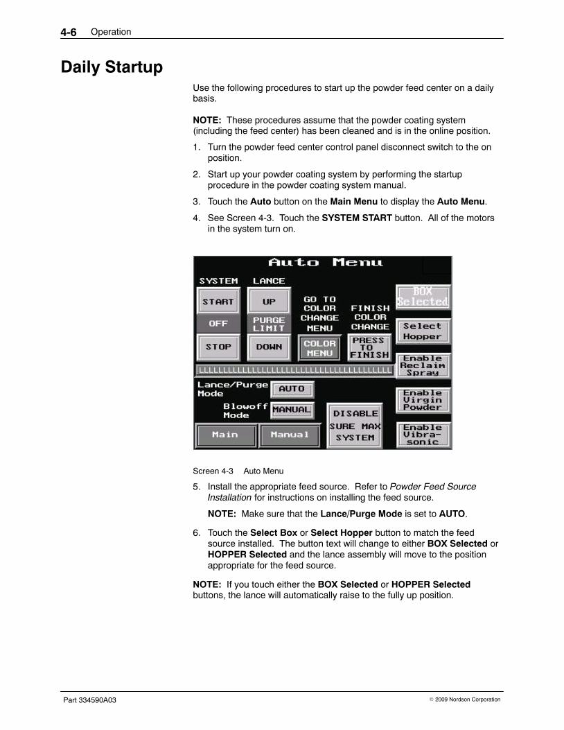
4. See Screen 4-3. Touch the SYSTEM START button. All of the motorsin the system turn on.
Screen 4-3 Auto Menu
5. Install the appropriate feed source. Refer to Powder Feed SourceInstallation for instructions on installing the feed source.
NOTE: Make sure that the Lance/Purge Mode is set to AUTO.
6. Touch the Select Box or Select Hopper button to match the feedsource installed. The button text will change to either BOX Selected orHOPPER Selected and the lance assembly will move to the positionappropriate for the feed source.
NOTE: If you touch either the BOX Selected or HOPPER Selectedbuttons, the lance will automatically raise to the fully up position.

Operation 4-7
Part 334590A03� 2009 Nordson Corporation
7. Adjust the fluidizing air pressure:
� Powder Box: Adjust the needle valve on the lance assembly.
� Fluidizing Hopper: Adjust the fluidizing air at the powder feedcenter’s pneumatic panel. (Recommended setting: 0.3 bar (5 psi))
8. Touch the following buttons (as applicable) to activate options for yourfeed center:
� Enable Reclaim Spray
� Enable Virgin Powder
� Enable Vibrasonic
9. Start spraying powder.
Powder Feed Source InstallationUse one of the following procedures to install a powder feed source into thepowder feed center.
Powder Box Installation1. On the Auto Menu, set the Lance/Purge Mode to MANUAL.
2. See Figure 4-1. Touch the LANCE UP button to raise the lanceassembly (5).
3. Loosen the thumb screw (1) and slide the level sensor probe (4) downuntil it stops against the top of the probe bracket (2). Tighten the thumbscrew.
4. Open the box of powder and place it on the vibratory table.
5. Make sure that the box is centered under the lance assembly, thensecure the box to the vibratory table using the box guides and clampinglevers.
6. Set the Lance/Purge Mode to AUTO.
When all feed center modes are set to AUTO, the lance assembly lowers asthe powder level falls. When the level sensor senses that the lanceassembly has lowered below the box limit, the sensor activates either alow-powder alarm or automatic bulk feed.

Operation4-8
Part 334590A03 � 2009 Nordson Corporation
Fluidizing Hopper Installation1. On the Auto Menu, set the Lance/Purge Mode to MANUAL.
2. See Figure 4-1. Touch the LANCE UP button to raise the lanceassembly (5).
3. Loosen the thumb screw (1). Slide the level sensor probe (4) up untilthe collar (3) stops against the bottom of the probe bracket (2), thentighten the thumb screw.
4. Remove the front box guide from the vibratory table and set it aside.
5. Place the hopper on the vibratory table. Make sure that the hopper iscentered under the lance assembly, then remove the lid from the hopper.
6. Connect the fluidizing air tubing to the air fitting on the hopper.
NOTE: Adjust the fluidizing air pressure at the feed center’s pneumaticpanel as necessary.
7. Set the Lance/Purge Mode to AUTO.
When all feed center modes are set to AUTO, the lance assembly stays at afixed position. When the level sensor senses that the powder level hasfallen below the hopper limit, the sensor activates either a low-powder alarmor automatic bulk feed.
3
2
4
5
Hopper
Box
1
Figure 4-1 Level Sensor Probe Adjustment
1. Thumb screw2. Probe bracket3. Collar
4. Level sensor probe5. Lance assembly
Note: Level sensor probe shown in the powder box (down) position.

Operation 4-9
Part 334590A03� 2009 Nordson Corporation
ShutdownUse the following procedure to shut down the powder feed center.
1. Move the system offline, if applicable.
2. Clean the system by performing the color change process, but do notinstall a new powder source. Refer to the Color Change section formore information.
NOTE: If you are shutting down the system for a short break in production,do not perform steps 3 or 4.
3. See Screen 4-3.
From the Auto Menu, touch the SYSTEM STOP button. All of themotors in the system turn off.
4. If you will be shutting down the powder feed center for maintenance,repair, or an extended period of time, perform these steps:
a. Press the SYSTEM STOP button on the system control panel.
b. Turn the disconnect switch on the powder feed center control panelto the off position.

Operation4-10
Part 334590A03 � 2009 Nordson Corporation

Color Change 5-1
Part 334590A03� 2009 Nordson Corporation
Section 5Color Change
WARNING: Allow only qualified personnel to perform the following tasks.Follow the safety instructions in this document and all other relateddocumentation.
IntroductionUse the following procedures to change colors in the powder feed center.Follow the procedures listed in your system and application equipmentmanuals to clean the booth canopy and powder application equipment.
The operators start the automated tasks of the color change process byusing the Color Change and Auto Menu screens.
NOTE: Your powder coating system may not have all of the equipment orfunctions described in this section. Disregard any steps that refer toequipment or functions that are not present in your system.
Types of Color Changes Refer to Table 5-1 for descriptions of the two types of color changes.
Table 5-1 Types of Color Changes
Color Change Type Description
Similar Shade When changing from either
� a light powder to another light powder, or
� a dark powder to another dark powder.
Different Shade
or
Different Powder Type
When changing from either
� a light powder to a dark powder,
� a dark powder to a light powder,
� a standard powder to a special powder, or
� a special powder to a standard powder.
NOTE: The time that it takes to perform a different shade/powder typecolor change will depend on how many spray guns are in your system.

Color Change5-2
Part 334590A03 � 2009 Nordson Corporation
Types of Color Changes (contd)
Refer to Table 5-2.
The powder feed center may be used with two types of powder coatingsystems. The powder feed center has a specific color change process foreach type of system.
Table 5-2 Compatible Powder Coating Systems
System Type Description
Quick Color Change These systems are specially equipped toquickly perform color changes. Quick colorchange systems include the followingNordson product lines:
� Colormax
� Sure Clean
Conventional These systems use conventional cyclone orcartridge technology. Conventional colorchange systems include the followingNordson product lines:
� Cyclo-Kinetic
� Excel
� Horizon

Color Change 5-3
Part 334590A03� 2009 Nordson Corporation
Performing a Color ChangeTwo operators typically perform the color change process. The twooperators are responsible for cleaning the following things:
Operator Responsible for theseBooth Components
Refer to thisDocumentation
A � Booth interior
� Cyclones and/or colormodule
Powder coating systemmanual
B Powder feed center � Appropriate colorchange procedure inthis section, or
� Quick color changepowder coating systemmanual
Operators A and B typically perform their respective color changeprocedures at the same time.
Color Change Control MenuThe operators start the automated tasks of the color change process byusing the Color Change Control and Auto Menu screens.

Color Change5-4
Part 334590A03 � 2009 Nordson Corporation
Menu NavigationFigure 5-1 shows how to navigate through the menus used to perform acolor change.
Figure 5-1 Color Change Menu Navigation
Color Change 5-5
Part 334590A03� 2009 Nordson Corporation
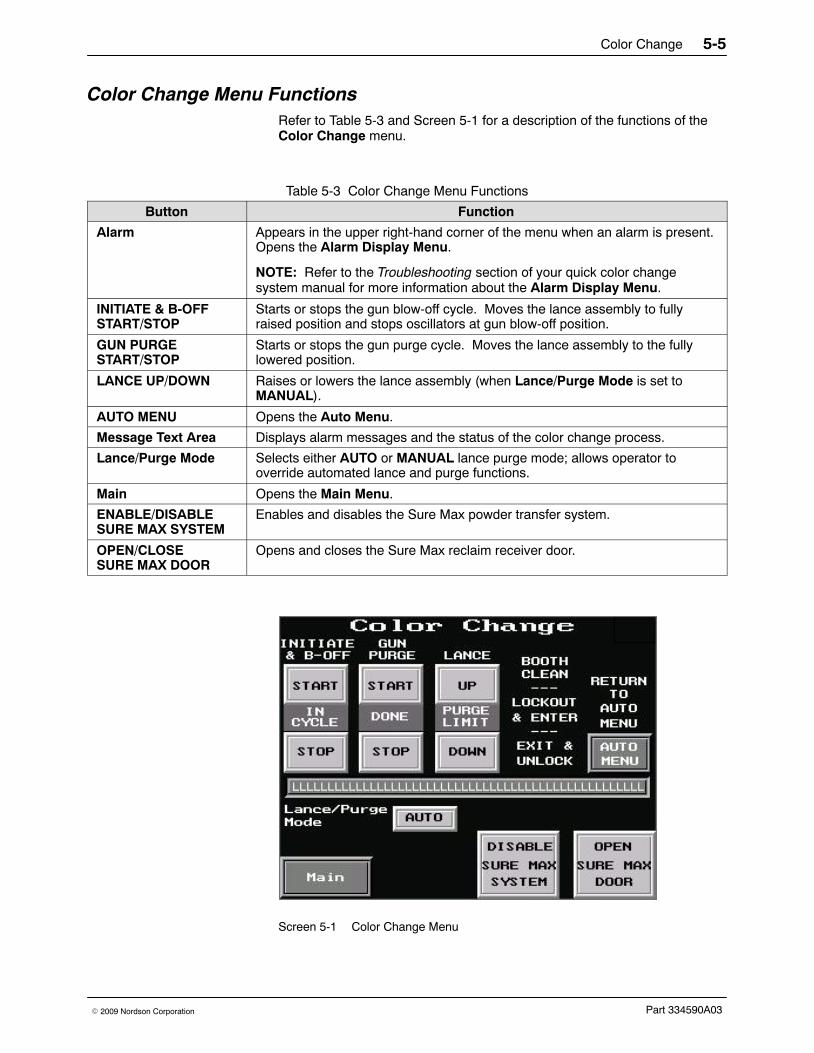
Color Change Menu FunctionsRefer to Table 5-3 and Screen 5-1 for a description of the functions of theColor Change menu.
Table 5-3 Color Change Menu Functions
Button Function
Alarm Appears in the upper right-hand corner of the menu when an alarm is present.Opens the Alarm Display Menu.
NOTE: Refer to the Troubleshooting section of your quick color changesystem manual for more information about the Alarm Display Menu.
INITIATE & B-OFFSTART/STOP
Starts or stops the gun blow-off cycle. Moves the lance assembly to fullyraised position and stops oscillators at gun blow-off position.
GUN PURGESTART/STOP
Starts or stops the gun purge cycle. Moves the lance assembly to the fullylowered position.
LANCE UP/DOWN Raises or lowers the lance assembly (when Lance/Purge Mode is set toMANUAL).
AUTO MENU Opens the Auto Menu.
Message Text Area Displays alarm messages and the status of the color change process.
Lance/Purge Mode Selects either AUTO or MANUAL lance purge mode; allows operator tooverride automated lance and purge functions.
Main Opens the Main Menu.
ENABLE/DISABLESURE MAX SYSTEM
Enables and disables the Sure Max powder transfer system.
OPEN/CLOSE SURE MAX DOOR
Opens and closes the Sure Max reclaim receiver door.
Screen 5-1 Color Change Menu

Color Change5-6
Part 334590A03 � 2009 Nordson Corporation
Quick Color Change System Color Change Process Use the following chart to complete the color change process in a Colormaxor Sure Clean powder coating system.
NOTE: Refer to the Color Change section in your quick-color changepowder coating system manual for a more detailed description of the colorchange process.
Procedure
Tasks
Operator A
See Figure 5-2
Operator B
See Figure 5-3
1 Close the booth doors and, if applicable, move the booth offline.
2 From the Auto Menu, touch the COLOR MENU button to access the Color Change menu.
Touch the INITIATE & B-OFF START button. The system automatically performs thefollowing tasks:
NOTE: Perform procedure 3 while the system is performing these tasks.
NOTE: To interrupt the gun blow-off cycle, touch the INITIATE & B-OFF STOP button.
� Oscillators (if used) stop and the spray guns move into the fully extended position.
� Sieve, fluidizing air, and vibrating table stop and lance assembly raises.
� In/out gun positioners retract (one at a time) and powder is blown off the spray guns.
When the gun blow-off cycle is complete, the COLOR CHANGE CYCLE DONE indicatorflashes.
3 1. Disengage the coupling (2) connectingthe reclaim conveyor line (1) to thereclaim port (4).
2. Remove the scrap cap (7) from the scrapport (5).
3. Open the transfer pan (8) and and blowout all powder remaining in the pan.
4. Send three cleaning sponges through thereclaim conveyor line.
5. Install the reclaim plug (3) in the reclaimconveyor line (1).
NOTE: Do not close the transfer pan at thistime.
1. Unclamp the underpan (3) and turn itcounterclockwise until the chute isdirectly over the chute on the back wallof the feed center.
NOTE: If you are using the optionalfluidizing hopper, disconnect the airtubing before removing the hopper fromthe feed center.
2. Remove the powder source from thefeed center.
Continued...

Color Change 5-7
Part 334590A03� 2009 Nordson Corporation
Procedure
Tasks
Operator A
See Figure 5-2
Operator B
See Figure 5-3
4 Touch the GUN PURGE START button. The system automatically performs the followingtasks:
NOTE: Perform procedure 5 while the system is performing these tasks.
NOTE: To interrupt the gun purge cycle, touch the GUN PURGE STOP button.
� Lance assembly lowers onto the purge manifold.
� Purge manifold sends pulses of air through the lances, pumps, feed hoses, and sprayguns.
� Lance assembly raises and sieve restarts.
When the gun purge cycle is complete, the COLOR CHANGE CYCLE DONE indicatorflashes.
5 Blow off all door seams from the outside ofthe booth.
Blow powder off the lance assembly (7).
Continued...
18
2
9
7
10
3
654
Figure 5-2 Operator A Color Change Tasks
1. Reclaim conveyor line2. Reclaim conveyor line coupling3. Reclaim plug4. Reclaim port
5. Scrap port6. Scrap conveyor line7. Scrap cap
8. Transfer pan9. Scrap receiver
10. Cyclone access doors
Color Change5-8
Part 334590A03 � 2009 Nordson Corporation
Quick Color Change System Color Change Process (contd)
Procedure
Tasks
Operator A
See Figure 5-2
Operator B
See Figure 5-3
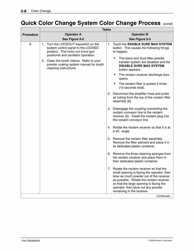
6 1. Turn the LOCKOUT keyswitch on thesystem control panel to the LOCKEDposition. This locks out in/out gunpositioner and oscillator operation.
2. Clean the booth interior. Refer to yourpowder coating system manual for boothcleaning instructions.
1. Touch the ENABLE SURE MAX SYSTEMbutton. This causes the following thingsto happen:
� The sieve and Sure Max powdertransfer system are disabled and theDISABLE SURE MAX SYSTEMbutton appears.
� The reclaim receiver discharge dooropens.
� The reclaim filter is pulsed 3 times(10 seconds total).
2. Disconnect the amplifier hose and pulseair tubing from the top of the reclaim filterassembly (6).
3. Disengage the coupling connecting thereclaim conveyor line to the reclaimreceiver (5). Install the reclaim plug intothe reclaim conveyor line.
4. Rotate the reclaim receiver so that it is ata 45� angle.
5. Remove the reclaim filter assembly.Remove the filter element and place it inits dedicated plastic container.
6. Remove the three cleaning sponges fromthe reclaim receiver and place them intheir dedicated plastic container.
7. Rotate the reclaim receiver so that thesmall opening is facing the operator, thenblow as much powder out of the receiveras possible. Rotate the reclaim receiverso that the large opening is facing theoperator, then blow out any powderremaining in the receiver.
Continued...

Color Change 5-9
Part 334590A03� 2009 Nordson Corporation
1
2
3
4
5
8
7
6
9
Figure 5-3 Operator B Color Change Tasks
1. Sieve deck2. Sieve screen3. Sieve underpan
4. Sieve5. Reclaim receiver6. Reclaim filter assembly
7. Lance assembly8. Feed hose manifold9. Vacuum diverter handle

Color Change5-10
Part 334590A03 � 2009 Nordson Corporation
Procedure
Tasks
Operator A
See Figure 5-2
Operator B
See Figure 5-3
7 1. Open the access doors on the cyclonesvertical ducts and blow all powder out ofthe vertical duct. Close and latch theaccess doors when done.
2. Blow off any powder remaining in thetransfer pan.
3. Remove the plug (3) from the conveyorline (1) and install it into the reclaimport (4).
4. Open the cyclone access doors (10) andblow off all interior surfaces of thecyclones.
5. Depending on whether the system will beoperating in either spray-to-reclaim orspray-to-waste mode, follow one of theseprocedures:
Spray-to-Reclaim Mode Operation:
a. Close and latch the cyclone accessdoors (10).
b. Close and latch the transfer pan (8).
c. Install the scrap conveyor line (6)onto the scrap port (5).
Spray-to-Waste Mode Operation:
Leave the cyclone access doors (10) andtransfer pan (8) open.
NOTE: Each color must have a dedicatedreclaim filter element. Using a filter elementfor multiple colors will result in crosscontamination.
1. Install the appropriate color-specific filterelement and install the filter assembly (6)into the reclaim receiver (5).
2. Rotate the reclaim receiver so that it is inthe upright position.
3. Connect the amplifier hose, pulse airtubing, and reclaim conveyor line to thereclaim receiver.
4. Touch the CLOSE SURE MAX DOORbutton to close the reclaim receiver door.
NOTE: If your system has the optionalVibrasonic sieve screen, unplug theVibrasonic transducer cable from its supportbracket and use caution when cleaningaround the screen’s Vibrasonic transducer.
5. Remove the sieve deck (1) andscreen (2).
� Similar Shade Color Change: Blowoff the sieve screen.
� Different Shade Color Change: Setthe sieve screen aside and clean itlater. Install a clean sieve screen.
6. Blow off the sieve deck andunderpan (3). Turn the underpanclockwise until the chute is directedtoward the lance assembly (7).
7. Install the appropriate sieve screen andthe sieve deck, and connect theVibrasonic transducer cable if applicable.
8. Touch the DISABLE SURE MAX buttonto enable the Sure Max powder transfersystem. Turn the vacuum diverterhandle to the counterclockwise position.
� Similar Shade Color Change: Installthe powder source into the feed centerand connect the fluidizing air tubing (ifapplicable).
� Different Shade Color Change: Do notinstall a new powder source until the endof procedure 8.
Continued...

Color Change 5-11
Part 334590A03� 2009 Nordson Corporation
Procedure
Tasks
Operator A
See Figure 5-2
Operator B
See Figure 5-3
NOTE: Perform procedure 8 only if you are performing a different shade color change. If you areperforming a similar shade color change, proceed to procedure 9.
8 Remove the powder feed hose from eachspray gun and install the other feed hose.
1. Remove the feed hose manifolds (8)from the lance assembly (7).
2. Blow down into the powder pumps on thelance assembly to clear away anyremaining powder.
3. Store the feed hoses and manifoldassemblies in the appropriate hoselocker.
4. Remove the appropriate feed hoses andmanifold assemblies from the hoselocker and install them onto the lanceassembly.
5. Install the new powder feed source andconnect the fluidizing air tubing, ifapplicable.
9 1. Turn the LOCKOUT keyswitch on the system control panel to the NORMAL position.
2. From the Auto Menu, touch the FINISH COLOR CHANGE PRESS TO FINISH button.The spray guns move back into the booth and begin oscillating, if applicable.
3. Touch either the Select Box or Select Hopper button to lower the lance assembly to theappropriate location.
4. If you want to operate the booth in spray-to-reclaim mode, touch the Enable WasteSpray button. The button’s text changes to Enable Reclaim Spray to indicate thecurrently selected operating mode.
NOTE: After a few minutes, the powder in the feed source will fluidize and the system willstart spraying powder. Spray approximately 0.5 kg (one lb) of powder to waste beforeperforming procedure 10. The amount of time that it will take to spray 0.5 kg (one lb) ofpowder will vary depending on the components in your system. Spraying the powder towaste seasons the ducts and cyclones to allow for more effective powder reclaim.
10 Spray-to-Reclaim Mode Operation Only:
1. Disengage the scrap conveyor line (6)from the scrap port (5)
2. Remove the plug (3) from the reclaimport (4) and set it aside.
3. Install the scrap cap (7) onto the scrapport (5).
4. Install the reclaim conveyor line (1) andcoupling (2) onto the reclaim port (4).
Spray-to-Reclaim Mode Operation Only:
Turn the vacuum diverter handle (9) to thefully clockwise position.

Color Change5-12
Part 334590A03 � 2009 Nordson Corporation
Changing the Sure Max Filter ElementUse the following procedure to change the filter element in either thereclaim or scrap receiver.
RemovalSee Figure 5-4.
1. Loosen and remove the hose clamp (7) using the flexible nut driversupplied with the Sure Max powder transfer system.
2. Remove the filter retaining nut (5) using the flexible nut driver.
3. Remove the filter element (6) from the filter basket (3).
4. Reach inside the top (clean side) of the filter element and push out thefilter element’s inner cone.
CAUTION: Do not vacuum the inside surface (clean side) of the filterelement. Failure to observe this caution may cause the powder to becomemore embedded in the filter media, making it more difficult to clean andcausing further blockage.
5. Using a soft brush attachment, vacuum the outside surface of the filterelement, then put the filter in its storage container.
6. Remove the grommet (4) from around the air shock tank stem (2).
7. Remove the filter basket (3) and seal (1).
8. Blow off all powder from the Sure Max filter assembly and itscomponents.
NOTE: The Sure Max filter element can be washed if it is either clogged orneeded for use with another color powder. Refer to Washing the Sure MaxFilter Element for more information.
InstallationSee Figure 5-4.
1. Install the seal (1) onto the top of the filter basket (3).
2. Slide the new filter element (6) onto the filter basket. Make sure that thebottom of the filter element covers the basket seal.
3. Install the hose clamp (7) over the filter basket so that it covers thebasket seal. Tighten the hose clamp only enough to hold it in place onthe filter basket assembly.
4. Install the filter basket assembly onto the filter housing assembly,making sure that the air shock tank stem (2) goes through the hole inthe filter element.
5. Install the grommet (4) around the air shock tank stem.
6. Install the filter retaining nut (5) onto the air shock tank stem. Tightenthe retaining nut using the flexible nut driver.

Color Change 5-13
Part 334590A03� 2009 Nordson Corporation
CAUTION: Make sure that there are no folds in the filter element when youtighten the hose clamp. Folds in the filter element may cause powder topass the filter, causing powder cross contamination and vacuum amplifierdamage.
7. Tighten the hose clamp using the flexible nut driver.
3
4
2
1
6
5
7
Figure 5-4 Changing the Sure Max Filter Element
1. Basket seal2. Air shock tank stem3. Filter basket
4. Grommet5. Filter retaining nut
6. Filter element7. Hose clamp

Color Change5-14
Part 334590A03 � 2009 Nordson Corporation
Washing the Sure Max Filter Element NOTE: Repeated washing can degrade the filter element performance.How many times the filter element may be washed will depend on howmuch it is used in between washes. Nordson Corporation recommendsreplacing the filter element with a new one after 2−4 washes.
The Sure Max filter element can be washed if the filter element is either
� needed for use with a different powder, or
� clogged due to continuous use.
These are indications that the filter element is clogged:
� The transfer pan has large amounts of powder in it while theSure Max system is operating.
� During the color change process, the cleaning sponges do not comethrough the vacuum conveyor line easily.
� The Sure Max differential pressure gauge reading is higher than8-in. wc.
Use this procedure to wash the Sure Max filter element.
1. Remove the filter element from the filter assembly. Refer to Changingthe Sure Max Filter Element for instructions.
2. Gently knock the filter element against the screen in front of the feedcenter cartridge filters and shake it to remove as much powder aspossible.
3. Reach inside the top (clean side) of the filter element and push out thefilter element’s inner cone.
CAUTION: Do not vacuum the inside surface (clean side) of the filterelement. Failure to observe this caution may cause the powder to becomemore embedded in the filter media, making it more difficult to clean andcausing further blockage.
4. Using a soft brush attachment, vacuum the outside surface of the filterelement.
CAUTION: Do not use detergent when washing the filter element. Usingdetergent will damage the filter.
5. Wash the filter element in a standard commercial or residential washingmachine in the Hand Wash cycle using cold water (40 �C).
6. Remove the filter element from the washing machine and form the filterelement into its normal shape.
7. Before installing the filter element, allow it to air dry for 24 hours or untilit is completely dry.

Color Change 5-15
Part 334590A03� 2009 Nordson Corporation
Conventional System Color Change Process Use the following chart to complete the color change process in aCyclo-Kinetic, Excel, or Horizon powder coating system.
NOTE: Refer to your powder coating system manual for instructions forcleaning your booth during the color change process.
Procedure TasksSee Figure 5-5
1 If applicable, move the booth offline.
2 From the Auto Menu, touch the COLOR MENU button to access the Color Change menu.
Touch the INITIATE & B-OFF START button. The system automatically performs thefollowing tasks:
NOTE: Perform procedure 3 while the system is performing these tasks.
NOTE: To interrupt the gun blow-off cycle, touch the INITIATE & B-OFF STOP button.
� Oscillators (if used) stop.
� Sieve, fluidizing air, and vibrating table stop, and lance assembly raises.
When the gun blow-off cycle is complete, the COLOR CHANGE CYCLE DONE indicator willflash.
3 1. Unclamp the underpan (3) and turn it counterclockwise until the chute is directly over thechute on the back wall of the feed center.
NOTE: If you are using the optional fluidizing hopper, disconnect the air tubing beforeremoving the hopper from the feed center.
2. Remove the powder source from the feed center.
4 Touch the GUN PURGE START button. The system automatically performs the followingtasks:
NOTE: Perform procedure 5 while the system is performing these tasks.
NOTE: To interrupt the gun purge cycle, touch the GUN PURGE STOP button.
� Lance assembly lowers onto the purge manifold.
� Purge manifold sends pulses of air through the lances, pumps, feed hoses, and sprayguns.
� Lance assembly raises.
When the gun purge cycle is complete, the COLOR CHANGE CYCLE DONE indicator willflash.
5 Blow powder off the lance assembly (6).
6 Turn the LOCKOUT keyswitch on the system control panel to the LOCKED position. Thislocks out oscillator operation so that an operator may enter the booth to clean the interior.
Continued...

Color Change5-16
Part 334590A03 � 2009 Nordson Corporation
Conventional System Color Change Process (contd)
Procedure TasksSee Figure 5-5
7 NOTE: If your system has the optional Vibrasonic sieve screen, unplug the Vibrasonictransducer cable from its support bracket and use caution when cleaning around thescreen’s Vibrasonic transducer. Refer to the Options section for Vibrasonic systemcomponent locations.
1. Remove the sieve deck (1) and sieve screen (2).
� Similar Shade Color Change: Blow off the sieve screen.
� Different Shade Color Change: Set the sieve screen aside and clean it later.
2. Blow off the sieve deck and underpan (3). Turn the underpan clockwise until the chute isdirected toward the lance assembly (6).
3. Install the appropriate sieve screen and the sieve deck, and connect the Vibrasonictransducer cable, if applicable.
NOTE: Only perform procedure 8 if you are performing a different shade color change. If you areperforming a similar shade color change, proceed to procedure 9.
8 1. Remove the feed hose manifold (5) from the lance assembly (6).
2. Blow down into the powder pumps on the lance assembly to clear away any remainingpowder.
3. Install the other feed hose manifold. Switch the powder feed hoses at the back of eachspray gun.
9 Install a new powder source into the powder feed center. Refer to Powder Feed SourceInstallation in the Operation section for instructions.
NOTE: If you are using the optional fluidizing hopper, connect the air tubing after installingthe hopper into the feed center.
10 1. Turn the LOCKOUT keyswitch on the system control panel to the NORMAL position.
2. From the Auto Menu, touch the FINISH COLOR CHANGE PRESS TO FINISH button.
3. Touch either the Select Box or Select Hopper button to lower the lance assembly to theappropriate location.
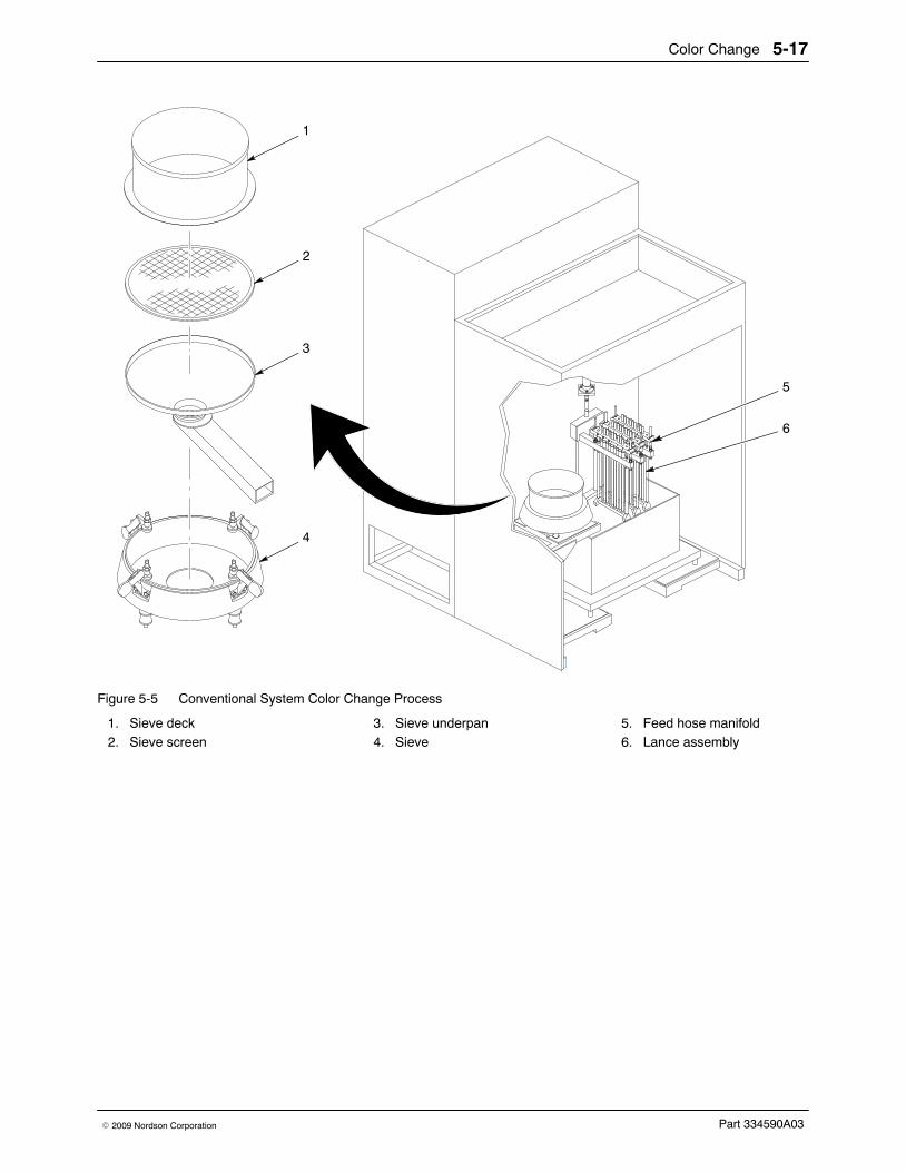
Color Change 5-17
Part 334590A03� 2009 Nordson Corporation
1
2
3
4
5
6
Figure 5-5 Conventional System Color Change Process
1. Sieve deck2. Sieve screen
3. Sieve underpan4. Sieve
5. Feed hose manifold6. Lance assembly

Color Change5-18
Part 334590A03 � 2009 Nordson Corporation

Maintenance 6-1
Part 334590A03� 2009 Nordson Corporation
Section 6Maintenance
WARNING: Allow only qualified personnel to perform the following tasks.Follow the safety instructions in this document and all other relateddocumentation.
Daily MaintenanceNOTE: You may need to perform these procedures more or less often,depending on your application requirements.
Table 6-1 Daily Maintenance Procedures
Component Maintenance Procedure
Sieve Disassemble and clean the sieve. Inspect the sieve screen and replace it ifthere is impact fusion present or the screen is damaged.
Sure Max PowderTransfer System(If Applicable)
Disassemble and clean the Sure Max reclaim receiver. Inspect each color’sreclaim filter and replace if damaged.
Empty the Sure Max scrap receiver. Inspect the scrap filter and replace ifdamaged.
Check all vacuum hoses for blockages. Clean or replace them if necessary.
Cables and FeedHoses
Check all external cables and powder feed hoses for damage. Replace themif necessary.
Waste Hopper Turn off the exhaust fan and check the level of powder in the waste hopper. Ifthe powder level is above 1/2 full, empty the waste hopper. Refer to Emptyingthe Waste Hopper in this section for instructions.
Pumps Disassemble the pumps and blow off their parts with low-pressure,compressed air. Replace any worn parts.
Cartridge Filters Check the seals around the cartridge filters. If the cartridge filters are notsealing properly, tighten them.
Powder Supply Check the powder supply level regularly and add powder as necessary.

Maintenance6-2
Part 334590A03 � 2009 Nordson Corporation
Emptying the Waste HopperNOTE: You may choose to have a single, shared scrap drum for the feedcenter and the afterfilter. In this application, the feed center’s scrap transferhose may remain connected to the scrap drum at all times, allowing you tofrequently empty the feed center’s waste hopper to keep the powder leveldown.
See Figure 6-1.
1. Secure the waste lid (6) to an empty 55-gallon drum (3).
2. Connect the ground clamp (7) to a true earth ground.
3. Attach a 3/4-in. transfer hose (8) between the transfer pump (9) and ahose connector (5) on the waste lid. Use hose clamps on both ends ofthe transfer hose.
NOTE: Make sure that all unused hose connectors on the waste lid areplugged.
4. Attach the vent hose (2) to the waste lid vent stub (4). Attach the otherend of the vent hose to the vent stub (1) on the opposite side of the feedcenter.
5. Touch the TRANSFER PUMP ON button on the Manual Menu. Thefluidizing and flow air will turn on and the powder will be drawn out of thewaste hopper.
NOTE: The normal operating air pressure for the transfer pump is 2 bar(30 psi). The normal fluidizing air pressure is 0.5 bar (8 psi). Adjust the airpressures as needed at the feed center pneumatic panel.
6. While standing at the transfer pump side of the feed center, use a rubbersqueegee to pull the powder in the waste hopper toward the pick-uptube (10). Be careful not to damage the fluidizing plate at the bottom ofthe waste hopper.
7. When the transfer pump is not drawing any more powder out of thewaste hopper, touch the TRANSFER PUMP OFF button.

Maintenance 6-3
Part 334590A03� 2009 Nordson Corporation
1
4 5 6 7
10
2
3
8
9
Figure 6-1 Emptying the Waste Hopper
1. Feed center vent stub2. Vent hose3. 55-Gallon waste drum4. Waste lid vent stub
5. Hose connector6. Waste lid7. Ground clamp
8. 3/4-in. Transfer hose9. Transfer pump
10. Pick-up tube

Maintenance6-4
Part 334590A03 � 2009 Nordson Corporation
Periodic MaintenanceNOTE: You may need to perform these procedures more or less often,depending on your application requirements.
Table 6-2 Periodic Maintenance Procedures
Component Maintenance Procedure
Airflow Take regular airflow readings. A properly functioning powder feed centershould provide a face velocity of around 125 fpm. A lower reading indicatesclogged filters or a malfunctioning fan.
Fan Motor Perform the following checks regularly. Problems will be apparent if you noticechanges in the following factors.
� Pay attention to changes in vibration and noise levels.
� Take current readings regularly.
� Check all electrical connections regularly.
Cartridge Filters/FinalFilters
Check the differential pressure gauges on the pneumatic panel.
� Cartridge Filters: pulsing on demand at 3-in. wc
� Final Filters: warning at 4-in. wc; shutdown at 5-in. wc
Check all filters and replace them if necessary.
Remove the final filters and inspect the fan housing. Signs of powder insidethe fan section indicate a leaking cartridge filter.
Compressed AirSystem
Open the drop leg and use a clean, white cloth to check for contaminants.Correct any problems immediately.
Electrical System Tighten all electrical connections and inspect for loose or broken wires.
Check the electrical system for electrical safety every 12 months. The systemmust comply with all local, state, and federal codes.

Troubleshooting 7-1
Part 334590A03� 2009 Nordson Corporation
Section 7Troubleshooting
WARNING: Allow only qualified personnel to perform the following tasks.Follow the safety instructions in this document and all other relateddocumentation.
This section contains troubleshooting procedures. These procedures coveronly the most common problems that you may encounter. If you cannotsolve the problem with the information given here, contact your localNordson representative for help.
Table 7-1 Powder Supply Problems
No. Problem Page
1. Spray guns are surging or spitting; powder flow isinadequate or intermittent
7-2
2. Powder in feed source contaminated 7-2
3. Powder in feed source not fluidizing, or clouds ofpowder erupting from surface
7-2
4. Powder escaping from enclosure openings 7-3
Table 7-2 Purge Cycle Problems
No. Problem Page
1. Purge cycle will not start 7-4
Table 7-3 Sieve Problems
No. Problem Page
1. Vibrator does not start 7-6
2. Powder build up on sieve mesh 7-6
3. Excessive sieve noise 7-6
4. Contaminants in powder in feed source 7-6
Table 7-4 Filter Section Problems
No. Problem Page
1. Fan will not start 7-7
2. Loss of extraction 7-7
3. Final filters clogged; powder in the fan section 7-7

Troubleshooting7-2
Part 334590A03 � 2009 Nordson Corporation
Powder Supply Problems
Problem Possible Cause Corrective Action
1. Spray guns aresurging or spitting;powder flow isinadequate orintermittent
Insufficient air volume in feedhose; powder is settling out
Increase the atomizing air pressureand decrease the flow rate airpressure. Refer to the spray gun andcontrol unit manuals forrecommended air pressures andratios.
Powder in feed sourceinadequately fluidized; cavitiesforming in powder below pickuptube ends
Adjust the fluidizing air pressure. Thepowder should be gently boiling.Refer to problem 3.
Low powder level in feed source Add powder to the feed source.Refer to problem 3.
Powder pump venturi nozzles orthroats worn; pickup tube suckingair at connection to pump mountingarm; pump or pickup tube clogged
Clean the pump and pickup tube.Replace any worn parts. Replaceany damaged O-rings.
Obstruction in powder feed hose Disconnect the feed hose from thepump. Blow the powder out of thehose with compressed air. Make surethe hose is clear. Eliminate kinks orsevere bends in the hose. The hoseshould be no longer than 7.6 m (25 ft)with a maximum 2.7-m (9-ft) verticalrise.
Severe tribo-charging in powderfeed hose
Contact your Nordson Corporationrepresentative for a suitable hosematerial. Contact your powdersupplier.
Obstruction in spray gun Clean the spray gun. If you are usingconical nozzles, make sure there is a3 mm (0.125 in.) or larger gapbetween the deflector and the nozzle.
2. Powder in feedsource contaminated
Sieve screen damaged Replace the sieve screen.
Sieve screen not thoroughlycleaned before installation
Remove and clean the sieve screen.
3. Powder in feedsource not fluidizing,or clouds of powdererupting from surface
Fluidizing air pressure too low ortoo high
Check the powder in the feed source.Increase the fluidizing air pressureuntil the powder is gently boiling.Decrease the pressure if clouds ofpowder are erupting from the surface.
Moist or oil-contaminated powder Open the drain valve at the air-supplydrop leg and check the air supply forwater or oil. Check the filters,separators, and air dryer.
Replace the powder in the feedsource. Refer to the next possiblecause.
Continued...

Troubleshooting 7-3
Part 334590A03� 2009 Nordson Corporation
Corrective ActionPossible CauseProblem
3. Powder in feedsource not fluidizing,or clouds of powdererupting from surface (contd)
Systems with fluidizing hopperonly: Fluidizing plate gasketleaking, or fluidizing plate plugged,cracked, or installed incorrectly
Check for air leaks around thefluidizing plate gaskets. If leaks arefound, remove the plate and replacethe gasket.
Remove the fluidizing plate from thefluidizing box. Inspect it for stains,discoloration, polished surfaces, orcracks. Replace the fluidizing plate ifit is contaminated, plugged, ordamaged. Plate should be installedwith smooth surface up (in contactwith powder).
Incorrect ratio of reclaimed-to-newpowder
Change the transfer pump airpressure to increase or decrease thetransfer rate. Add new powder tofeed source. The powder supplyshould be no more than three partsreclaim-to-one part new powder.
Uneven distribution of powder infeed source
Check the powder and the fluidizingplate for contamination as previouslydescribed.
Vibratory table isolator mountsloose or damaged
Inspect the vibratory table isolatormounts. Tighten or replace them asnecessary. Refer to Vibratory TableIsolator Mount Replacement in theRepair section.
4. Powder escapingfrom enclosureopenings
Cartridge filters clogged; exhaustfan draw insufficient to retainpowder within enclosure
Check the cartridge filter pulsesequence and pulse the cartridgefilters for 30 minutes. Replace thecartridge filters if necessary.
Cross drafts interfering withexhaust fan draw
Check for cross drafts at theenclosure opening. Eliminate ordivert drafts.
Fan rotation backward Reverse the rotation of the motor.Refer to the Reversing MotorDirection procedure in this section.
Access panels not sealed Tighten knobs on all access panels.Check and replace the panel gasketsas necessary.
Cartridge filters leaking Check the cartridge filter mountingseal. Tighten or replace thecartridge.
Check the cartridge filters forpunctures. Replace as necessary.
Powder feed hose leak Check the powder feed hose for leaksor damage. Replace as necessary.
Powder pump leak Check all pump O-rings. Replaceany damaged O-rings.
Gaps in enclosure seams orgaskets
Caulk seams or replace gaskets.

Troubleshooting7-4
Part 334590A03 � 2009 Nordson Corporation
Purge Cycle Problems
Problem Possible Cause Corrective Action
1. Purge cycle will notstart
Bottom of stroke sensor and stopbolts out of alignment
Realign the sensor and stop boltsusing the Bottom of Stroke Sensorand Stop Bolt Realignmentprocedure.
Bottom of Stroke Sensor and Stop Bolt Realignment See Figure 7-1.
1. Remove the feed source from the powder feed center.
2. From the Color Change menu, touch the Lance/Purge Mode button sothat it displays MANUAL.
NOTE: To ensure that all lance assemblies will lower to the same location,make the same adjustments to both stop bolts.
3. Touch the LANCE DOWN button to lower the lance assembly. Lowerthe lance assembly until the pickup tubes (9) fully engage with the purgenozzles (10).
If the pickup tubes do not engage the purge nozzles, turn both stopbolts (7) clockwise one turn and touch the LANCE DOWN button again.Repeat if necessary.
4. Turn both stop bolts counterclockwise until their heads are firmly againstthe bottom of the linear slide (6). When both stop bolts are firmly inplace, lock them into position using the jam nuts (8).
NOTE: Figure 7-1 shows the typical locations of the three sensors on thecylinder rod. Use these dimensions only as a starting point for aligning thesensors.
5. Loosen the sensor bracket (4) and slide it up and down the cylinder roduntil the LED (5) illuminates. With the LED illuminated, tighten thesensor bracket.
6. Use the LANCE UP/DOWN buttons to make sure that the sensor LEDilluminates when the pickup tubes engage the purge nozzles. Readjustthe stop bolts and sensor if necessary.

Troubleshooting 7-5
Part 334590A03� 2009 Nordson Corporation
1
2
3
4
5
6
7
8
8
7
9
10
187 mm(7 in.)
center of light102 mm(4 in.)
center of light
279 mm(11 in.)
center of light
Figure 7-1 Bottom of Stroke Sensor and Stop Bolt Realignment
1. Hopper stop sensor2. Box stop sensor3. Bottom of stroke (purge) sensor4. Sensor bracket
5. Sensor LED6. Linear slide7. Stop bolts
8. Jam nuts9. Pickup tubes
10. Purge nozzles

Troubleshooting7-6
Part 334590A03 � 2009 Nordson Corporation
Sieve Problems
Problem Possible Cause Corrective Action
1. Vibrator does notstart
No input power Check the power supply.
Check the sieve power cable.
Vibrator capacitor failed Replace the vibrator.
Vibrator failed Replace the vibrator.
2. Powder build up onsieve mesh
Mesh not cleaned frequentlyenough
Clean the sieve mesh at morefrequent intervals. Upgrade toVibrasonic sieve screen if necessary.
Mesh size too small for powderbeing used
Use a sieve screen with a largermesh size. Upgrade to Vibrasonicsieve screen if necessary.
3. Excessive sieve noise Sieve deck or underpan not secure Tighten the clamps securing the sievedeck and underpan to the sieve.
Knobs or clamps not tightened;isolators loose or damaged; rubbersleeves damaged
Make sure the clamps are tight.Check the isolators for looseness ordamage. Tighten the isolatormounting screws. Check the rubbersleeves for damage and replace themif necessary.
4. Contaminants inpowder in feed source
Sieve screen torn Replace the screen.
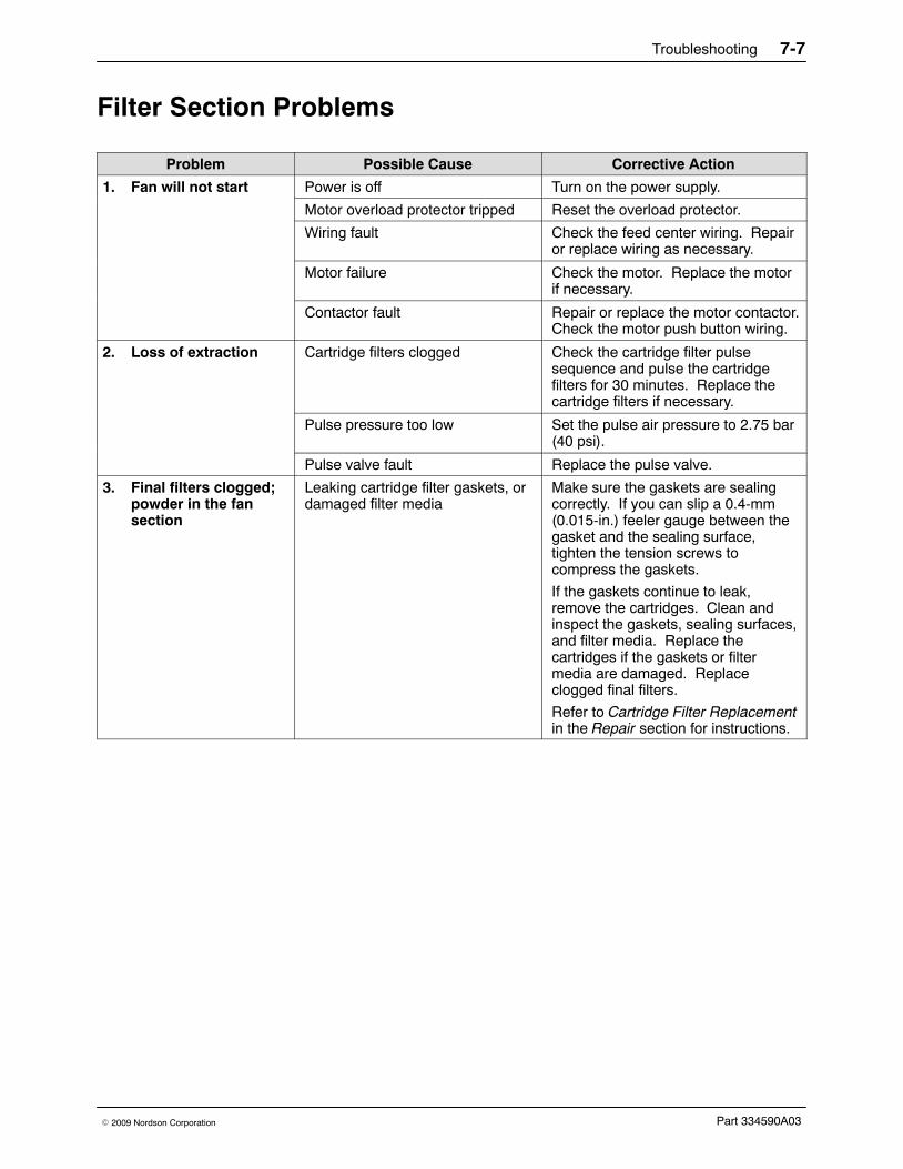
Troubleshooting 7-7
Part 334590A03� 2009 Nordson Corporation
Filter Section Problems
Problem Possible Cause Corrective Action
1. Fan will not start Power is off Turn on the power supply.
Motor overload protector tripped Reset the overload protector.
Wiring fault Check the feed center wiring. Repairor replace wiring as necessary.
Motor failure Check the motor. Replace the motorif necessary.
Contactor fault Repair or replace the motor contactor.Check the motor push button wiring.
2. Loss of extraction Cartridge filters clogged Check the cartridge filter pulsesequence and pulse the cartridgefilters for 30 minutes. Replace thecartridge filters if necessary.
Pulse pressure too low Set the pulse air pressure to 2.75 bar(40 psi).
Pulse valve fault Replace the pulse valve.
3. Final filters clogged;powder in the fansection
Leaking cartridge filter gaskets, ordamaged filter media
Make sure the gaskets are sealingcorrectly. If you can slip a 0.4-mm(0.015-in.) feeler gauge between thegasket and the sealing surface,tighten the tension screws tocompress the gaskets.
If the gaskets continue to leak,remove the cartridges. Clean andinspect the gaskets, sealing surfaces,and filter media. Replace thecartridges if the gaskets or filtermedia are damaged. Replaceclogged final filters.
Refer to Cartridge Filter Replacementin the Repair section for instructions.
Troubleshooting7-8
Part 334590A03 � 2009 Nordson Corporation

Repair 8-1
Part 334590A03� 2009 Nordson Corporation
Section 8Repair
WARNING: Allow only qualified personnel to perform the following tasks.Follow the safety instructions in this document and all other relateddocumentation.
IntroductionWARNING: Relieve system air pressure and lock out the air supply beforeperforming the following tasks. Failure to observe this warning may result inpersonal injury.
This section contains basic repair instructions for the powder feed center.Repair procedures for other system components are covered in their own,separate manuals.
NOTE: Contact your Nordson representative about any powder feed centerrepair procedures that are not covered in this section.
Cartridge Filter ReplacementNOTE: Two people are required to replace the cartridge filters. One personremoves hardware from above the cartridge filter. The other personremoves the old filters and holds the new filters up against the mountingplate.

Repair8-2
Part 334590A03 � 2009 Nordson Corporation
Removing the Cartridge FilterSee Figure 8-1.
WARNING: Relieve system air pressure and lock out the air supply beforeperforming the following tasks. Failure to observe this warning may result inpersonal injury.
1. Remove the pulse valve access panel (2) by removing the fourknobs (1). Open the cartridge filter access panel.
2. Pull up on the T-handle on the draw rod (8) to hold the cartridgefilter (10) against the mounting plate (7).
3. Remove the nut (3), lock washer (4), flat washer (5), and mountingbracket (6) from the draw rod. Save these parts for reuse.
4. Carefully lower the cartridge filter away from the mounting plate and outof the filter section. The centering bracket (9) and draw rod will stay inplace.
5. Unscrew the draw rod and remove the draw rod and centering bracketfrom the old cartridge filter.
Installing the Cartridge FilterSee Figure 8-1.
1. Thoroughly clean the sealing surface on the underside of the mountingplate (7). A dirty surface will prevent the cartridge filter gasket fromsealing properly and allow powder to leak into the fan section.
2. Remove the new cartridge filter (10) from its carton and inspect it fordamage. Do not use damaged cartridge filters.
3. Set the centering bracket (9) into the open end of the new cartridge filter.Slide the draw rod (8) through the centering bracket and screw the drawrod into the bottom of the cartridge filter.
4. Center the cartridge filter under the opening in the mounting plate. Usethe draw rod’s T-handle to pull up the cartridge filter against themounting plate.
5. Install the mounting bracket (6) on the draw rod, making sure that theslots in the mounting bracket slip over the T-handle.
6. Install the flat washer (5), lock washer (4), and nut (3) onto the draw rod.Do not tighten the nut at this time.
7. Slip the ends of the mounting bracket into the locating slots around thefilter opening in the mounting plate.
8. Tighten the nut until the mounting and centering brackets are touching.This will compress the filter gasket (11) and seal the cartridge againstthe mounting plate.
9. Close the cartridge filter access panel and install the pulse valve accesspanel (2) using the four knobs (1).

Repair 8-3
Part 334590A03� 2009 Nordson Corporation
2
1
1
3
4
5
6
8
9
10
67
11
10
9
8
7
Figure 8-1 Cartridge Filter Replacement
1. Knobs2. Pulse valve access panel3. Nut4. Lock washer
5. Flat washer6. Mounting bracket7. Mounting plate8. Draw rod
9. Centering bracket10. Cartridge filter11. Gasket

Repair8-4
Part 334590A03 � 2009 Nordson Corporation
Final Filter ReplacementWARNING: Relieve system air pressure and lock out the air supply beforeperforming the following tasks. Failure to observe this warning may result inpersonal injury.
1. See Figure 8-2. Remove the upper and lower final filter brackets (2) byremoving the knobs (3).
2. Pull the old final filter (1) out of the powder feed center.
3. Inspect the inside of the fan housing. Vacuum out any powder that hasaccumulated inside the housing.
NOTE: If powder has accumulated inside the fan housing, check thecartridge filter media and gaskets. Tighten the cartridge filters’ mountinghardware to compress the gaskets or replace the cartridge filters.
4. Remove the new final filter from its carton and inspect it for damage. Donot use damaged final filters.
5. Slide the new final filter into the powder feed center.
6. Install the upper and lower final filter brackets and knobs.
7. Tighten the upper and lower clamping knobs to compress the final filterevenly on all four sides.
2
2
1
3
3
Figure 8-2 Final Filter Replacement
1. Final filter2. Brackets
3. Knobs
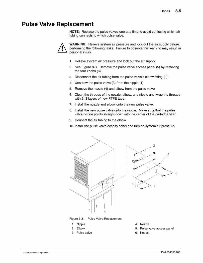
Repair 8-5
Part 334590A03� 2009 Nordson Corporation
Pulse Valve ReplacementNOTE: Replace the pulse valves one at a time to avoid confusing which airtubing connects to which pulse valve.
WARNING: Relieve system air pressure and lock out the air supply beforeperforming the following tasks. Failure to observe this warning may result inpersonal injury.
1. Relieve system air pressure and lock out the air supply.
2. See Figure 8-3. Remove the pulse valve access panel (5) by removingthe four knobs (6).
3. Disconnect the air tubing from the pulse valve’s elbow fitting (2).
4. Unscrew the pulse valve (3) from the nipple (1).
5. Remove the nozzle (4) and elbow from the pulse valve.
6. Clean the threads of the nozzle, elbow, and nipple and wrap the threadswith 2−3 layers of new PTFE tape.
7. Install the nozzle and elbow onto the new pulse valve.
8. Install the new pulse valve onto the nipple. Make sure that the pulsevalve nozzle points straight down into the center of the cartridge filter.
9. Connect the air tubing to the elbow.
10. Install the pulse valve access panel and turn on system air pressure.
5
2
1
3
4
6
6
Figure 8-3 Pulse Valve Replacement
1. Nipple2. Elbow3. Pulse valve
4. Nozzle5. Pulse valve access panel6. Knobs

Repair8-6
Part 334590A03 � 2009 Nordson Corporation
Waste Hopper Fluidizing Plate Replacement1. See Figure 8-4. Empty as much powder as possible from the waste
hopper. Refer to Emptying the Waste Hopper in the Maintenancesection for more information.
2. Open the cartridge filter access panels and vacuum out any remainingpowder in the waste hopper.
3. Turn off and lock out power to the powder feed center.
NOTE: The retaining angles (4) secure the fluidizing plate (5) to the bottomof the waste hopper.
4. Remove the M6 screws (1), lock washers (2), and flat washers (3)securing the retaining angles (4) to the fluid section.
5. Remove the retaining angles and fluidizing plate (5) from the wastehopper.
6. Set the new fluidizing plate smooth side up into the waste hopper.
7. Set the retaining angles on top of the fluidizing plate.
NOTE: As you tighten the retaining angles, push down on them tocompress the fluidizing plate gasket evenly.
8. Secure the retaining angles and fluidizing plate to the waste hopperusing the screws, lock washers, and flat washers.
5
4
12 3
Figure 8-4 Waste Hopper Fluidizing Plate Replacement
1. Screws (M6 x 1 in.)2. Lock washers (M6)
3. Flat washers (M6)4. Retaining angles
5. Fluidizing plate
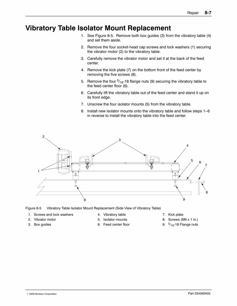
Repair 8-7
Part 334590A03� 2009 Nordson Corporation
Vibratory Table Isolator Mount Replacement 1. See Figure 8-5. Remove both box guides (3) from the vibratory table (4)
and set them aside.
2. Remove the four socket-head cap screws and lock washers (1) securingthe vibrator motor (2) to the vibratory table.
3. Carefully remove the vibrator motor and set it at the back of the feedcenter.
4. Remove the kick plate (7) on the bottom front of the feed center byremoving the five screws (8).
5. Remove the four 5/16-18 flange nuts (9) securing the vibratory table tothe feed center floor (6).
6. Carefully lift the vibratory table out of the feed center and stand it up onits front edge.
7. Unscrew the four isolator mounts (5) from the vibratory table.
8. Install new isolator mounts onto the vibratory table and follow steps 1−6in reverse to install the vibratory table into the feed center.
2
1
3
4
5 67
8
99
Figure 8-5 Vibratory Table Isolator Mount Replacement (Side View of Vibratory Table)
1. Screws and lock washers2. Vibrator motor3. Box guides
4. Vibratory table5. Isolator mounts6. Feed center floor
7. Kick plate8. Screws (M6 x 1 in.)9. 5/16-18 Flange nuts

Repair8-8
Part 334590A03 � 2009 Nordson Corporation

Parts 9-1
Part 334590A03� 2009 Nordson Corporation
Section 9Parts
Introduction To order parts, call the Nordson Finishing Customer Support Center at (800) 433−9319 or your local Nordson representative. Use these parts listsand illustrations to locate and describe parts correctly.
Using the Illustrated Parts List Numbers in the Item column correspond to numbers that identify parts inillustrations following each parts list. The code NS (not shown) indicatesthat a listed part is not illustrated. A dash (—) is used when the part numberapplies to all parts in the illustration.
The number in the Part column is the Nordson Corporation part number. Aseries of dashes in this column (- - - - - -) means the part cannot be orderedseparately.
The Description column gives the part name, as well as its dimensions andother characteristics when appropriate. Indentions show the relationshipsbetween assemblies, subassemblies, and parts.
Item Part Description Quantity Note— 0000000 Assembly 11 000000 � Subassembly 2 A2 000000 � � Part 1
� If you order the assembly, items 1 and 2 will be included.
� If you order item 1, item 2 will be included.
� If you order item 2, you will receive item 2 only.
The number in the Quantity column is the quantity required per unit,assembly, or subassembly. The code AR (As Required) is used if the partnumber is a bulk item ordered in quantities or if the quantity per assemblydepends on the product version or model.
Letters in the Note column refer to notes at the end of each parts list. Notescontain important information about usage and ordering. Special attentionshould be given to notes.

Parts9-2
Part 334590A03 � 2009 Nordson Corporation
Powder Feed Center AssemblyUse the following parts list to identify the subassemblies in the powder feedcenter. Subassembly parts are included in other parts lists in this section.
See Figure 9-1.
Item Part Description Quantity Note1 - - - - - - SURE MAX SYSTEM assembly 1
2 - - - - - - LANCE ARM assembly AR A
3 - - - - - - VIBRATORY TABLE and purge assembly 1
4 - - - - - - SIEVE assembly 1
5 - - - - - - FAN HOUSING assembly 1
6 - - - - - - BLOWDOWN HOUSING assembly 1
7 - - - - - - CARTRIDGE FILTER HOUSING assembly 1
8 - - - - - - FLUID BED assembly 1
9 249455 CONNECTOR, multi AR B
10 249461 SOCKET, multi connector AR B
11 1014550 LIGHT FIXTURE, 4 ft, 2 light 1
12 - - - - - - � BULB, light, florescent, 4 ft 2
13 - - - - - - PLATE, hose guide AR C
14 - - - - - - SCREW, hex head, M6 x 1.0 x 16-mm long 70
15 - - - - - - WASHER, M6, standard 120
16 - - - - - - WASHER, lock, M6, standard 120
17 - - - - - - CONTROL PANEL assembly 1 D
NOTE A: Your powder feed center has 1, 2, or 3 lance assemblies, depending on how many spray guns are in yoursystem.
B: Two of these parts are included for each lance assembly.
C: One of these parts is included for each lance assembly.
D: Contact your Nordson representative for control panel replacement parts.
AR: As Required

Parts 9-3
Part 334590A03� 2009 Nordson Corporation
3
1
2
4
17
13
11
98
7
6
5
10
12
141516
Figure 9-1 Powder Feed Center Assembly

Parts9-4
Part 334590A03 � 2009 Nordson Corporation
Sieve AssemblySee Figure 9-2.
Item Part Description Quantity Note1 1014560 SIEVE, vibratory, 15 in., 230/460 V, 60 Hz 1
2 - - - - - - � DECK, sieve 1
3 1014562 � SCREEN, sieve, vibratory, 15 in., 60 mesh 1 A, B
4 1014563 � � GASKET, screen, sieve, 15 in. 1
5 - - - - - - � UNDERPAN, sieve 1
6 1017602 � MOUNT, isolation, sieve 4
7 1017601 � MOTOR, sieve, vibratory 1
8 - - - - - - SCREW, cap, socket head, M10 x 1.5 x 25 mm 4
9 - - - - - - RAIL, mounting, sieve 2
10 - - - - - - BRACKET, sieve 2
11 - - - - - - SCREW, hex head, M10 x 1.5 x 65 long 4
12 - - - - - - WASHER, lock, M10 4
13 - - - - - - WASHER, flat, M10 4
NS 1014561 SCREEN, vibratory assembly, 40 mesh 1 A
NOTE A: Other mesh sizes are available. Contact your Nordson representative for information about other sievescreen mesh sizes.
B: An optional Vibrasonic sieve screen is available to replace the standard vibratory sieve screen. Refer tothe Options section for more information.

Parts 9-5
Part 334590A03� 2009 Nordson Corporation
7
8
9
10
111213
2
5
34
1
6
Figure 9-2 Sieve Assembly

Parts9-6
Part 334590A03 � 2009 Nordson Corporation
Sure Max Powder Transfer System
Sure Max System AssemblySee Figure 9-3.
Item Part Description Quantity Note1 1014514 HOSE, vacuum, 11/2 in. AR
2 - - - - - - VALVE, diverter, 11/2 in. 1
3 - - - - - - TUBING, 6 mm AR
4 1014512 ADAPTER, hose parking 1
5 1014513 HOSE, exhaust, Sure Max pump 6 ft
6 1013149 PUMP, Sure Max, with exhaust adapter and fittings 1
7 1013178 GASKET, inlet, outlet 2
8 - - - - - - COUPLER, shank, 11/2 in. 1
9 - - - - - - RECEIVER, vacuum, reclaim 1 A
NS 1015821 COUPLING, pipe, 51 mm, T-handle 2 B
NS 1014516 PLUG, quick-snap, 17/8 in. 2 C
NS 1013284 PADS, cleaning, Sure Max, 10 pack 1
NS 1014509 DRIVER, nut, flexible, 6/7 mm 1
NOTE A: Refer to Sure Max Receiver and Filter in this section for a breakdown of the parts included in thisassembly.
B: The pipe couplings, part 1015821, connect the reclaim conveyor line to the reclaim vacuum receiver andtransfer pan.
C: The quick-snap plugs, part 1014516, are used to plug the reclaim conveyor line during the color changeprocess.
NS: Not Shown
AR: As Required

Parts 9-7
Part 334590A03� 2009 Nordson Corporation
6
5
4
1
3
2
1
9
8
7
Figure 9-3 Sure Max System Assembly

Parts9-8
Part 334590A03 � 2009 Nordson Corporation
Sure Max Receiver and FilterSee Figure 9-4.
Item Part Description Quantity Note1 1015135 FILTER ASSEMBLY, Sure Max 2 A
2 - - - - - - � FITTING, banjo, male adapter/male thread 1
3 - - - - - - � TUBING, 6 mm AR
4 - - - - - - � ELBOW, 5 mm, 6-mm tubing 1
5 - - - - - - � ELBOW, 90 degree, 1/8-in. NPS, 6-mm tubing 2
6 1013178 � GASKET, filter head/inlet 2
7 1014511 � SEAL, body/module 1
8 - - - - - - � SCREW, socket head, cap, M5 x 20, stainlesssteel
16
9 1013286 � VALVE, air shock 1
10 - - - - - - � SCREW, hex head, M5 x 20, stainless steel 4
11 - - - - - - � WASHER, nylon, 5 mm 8
12 - - - - - - � TANK, air shock, 275 1
13 970968 � CLAMP, hose, 6-in. diameter 1
14 1013177 � SEAL, filter, outer, lid 1
15 - - - - - - � BASKET, filter, Sure Max 1
16 1013179 � FILTER ELEMENT, Sure Max 1
17 - - - - - - CLAMP, toggle 4
18 - - - - - - ELBOW, 1/8, 6 mm 2
19 - - - - - - BODY, Sure Max 1
20 - - - - - - COUPLER, shank, 11/2 in. 4
21 1014514 HOSE, vacuum, 11/2 in. AR
22 - - - - - - CANISTER, waste, Sure Max 1
NOTE A: The filter assembly, part 1015135, is used in both the reclaim and waste receivers.
AR: As Required
Filter ContainersUse these containers to store color-specific Sure Max filters and cleaningsponges when they are not in use. Use one dedicated container to storethe filter and cleaning sponges for each color used in your system.
Part Description Note1017571 CONTAINER, filter element, Sure Max A
1017572 CONTAINER, filter assembly, Sure Max B
NOTE A: Use this container to store a spare Sure Max filter element, part 1013179, and cleaning sponges whenthey are not in use.
B: Use this container to store a complete, spare Sure Max filter assembly, part 1015135, when it is not inuse.
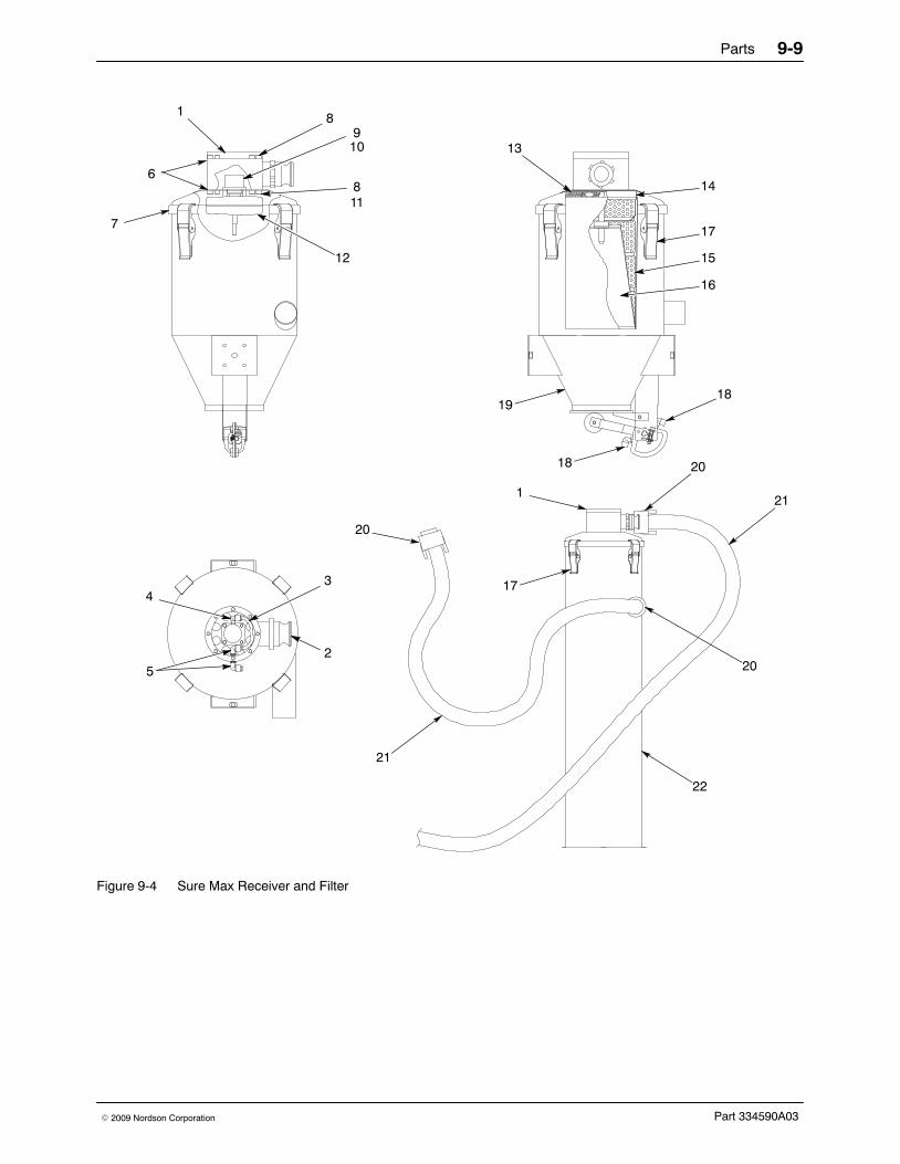
Parts 9-9
Part 334590A03� 2009 Nordson Corporation
43
5
8910
811
12
2
13
14
17
15
16
18
18
7
6
1
19
17
1
20
21
20
22
20
21
Figure 9-4 Sure Max Receiver and Filter

Parts9-10
Part 334590A03 � 2009 Nordson Corporation
Lance Arm AssemblySee Figure 9-5.
Item Part Description Quantity Note— 1014543 LANCE ARM assembly, pickup tubes 1 A
1 - - - - - - � CAM lock 2
2 1015680 � PLATE, hose, clamping 2
3 - - - - - - � GUIDE ROD, clamp plate 2
4 - - - - - - � WELDMENT, lance arm 1
5 - - - - - - � WASHER, plain, M10, standard 9
6 1014546 � LANCE, with lock nut 9
7 - - - - - - � PLATE, steady 1
8 - - - - - - � SCREW, hex head, M4 x 0.7 x 25-mm long 4
9 - - - - - - � WASHER, plain, M4, standard 4
10 1014557 � TUBE, fluidizing, assembly 1
11 1017574 � VALVE, flow control, 1/4-in. universal x10-mm tube
1
12 1003917 PUMP assembly, corona, inline, Tivar AR B, C
12 1003918 PUMP assembly, corona, inline, glass-filled PTFE AR B, D
13 1023136 CYLINDER assembly 1
14 1015208 SLIDE, vertical, assembly 1
15 1014553 PROBE, level sensor 1
16 1023925 CABLE, 4 pin, M12 connector, 5-m long 1
NOTE A: The powder feed center can be configured with one, two, or three lance assemblies.
B: Each lance assembly uses up to nine powder pumps.
C: Standard powder pump included with feed center.
D: Optional powder pump.
AR: As Required

Parts 9-11
Part 334590A03� 2009 Nordson Corporation
2
1
4
3
5
12
6
10
789
13
11
15
10
11
11
14
16
Figure 9-5 Lance Arm Assembly

Parts9-12
Part 334590A03 � 2009 Nordson Corporation
Vibratory Table and Purge AssemblySee Figure 9-6.
Item Part Description Quantity Note1 - - - - - - HOSE, 11/2 in., male NPT ends 1
2 1014642 VALVE, assembly, 3/4 in., with solenoid, 15-ft wire AR
3 1014643 REGULATOR, 1-in. NPT, 0−150 psi 1
4 - - - - - - HOSE, 1 in., 120-in. long, male NPT/female swivelends
1
5 - - - - - - TABLE TOP, vibratory 1
6 - - - - - - SCREW, socket head, flat, M5 x 0.8 x 10-mm long 12
7 1015207 MANIFOLD, purge assembly, pick-up tube AR A
8 1017557 � O-RING, 2.5-mm wide x 15-mm ID, Buna-N 9 B
9 1004110 � O-RING, 2-mm wide x 13-mm ID, Buna-N 9 B
10 - - - - - - � NOZZLE, purge 9 B
11 - - - - - - � MANIFOLD, cleaning 1
12 - - - - - - � SCREW, cap, socket head, M6 x 1.0 x 60-mmlong, stainless steel
6
13 1014549 PLATE, adapter, pick-up tube version AR
14 1028073 LATCH, vibratory table, powder feed center 4
15 - - - - - - GUIDE, box 2
16 - - - - - - TABLE, vibratory 1
17 1017559 MOUNT, vibration 5/16-18, 11/4 x 11/4 in. 4
18 - - - - - - ELBOW, 3/4-in. NPT x 3/4-in. JIC, 90 degree AR
19 - - - - - - HOSE, 3/4 in., 60-in. long, female swivel ends AR
20 1014539 VIBRATOR, M65, 115 V, 60 Hz 1
NS 1014543 PLUG, purge, socket set screw, M16 x 16 mm AR B
NS 1014515 PLATE, blank, purge assembly AR
NOTE A: The feed center can be configured with one, two, or three purge manifolds. The parts indented under theassembly, part 1015207, are the quantities needed for a single purge manifold assembly.
B: The quantity of purge nozzles and O-rings in your powder feed center will match the number of guns inyour system. Unused ports in the purge manifold will be plugged with the purge plug, part 1014543.
AR: As Required

Parts 9-13
Part 334590A03� 2009 Nordson Corporation
A
A
View A-A Enlarged
16
17
20
19 11 1213
1098
15
14
18
4
5
6
3
1
2
7
Figure 9-6 Vibratory Table and Purge Assembly

Parts9-14
Part 334590A03 � 2009 Nordson Corporation
Fan Housing AssemblySee Figure 9-7.
Item Part Description Quantity Note1 176367 KNOB, final filter 12
2 - - - - - - COVER, access, fan 1
3 - - - - - - GASKET, adhesive back, 1/2-in. wide x 1/4-in. thick AR
4 1017573 FAN, motor 1
6 176366 CLAMP, final filter, 18.5 x 2.75 in. 4
5 156995 FILTER, final, internal, 20 x 24 in. 2
AR: As Required
6
1
5
1
23
4
Figure 9-7 Fan Housing Assembly
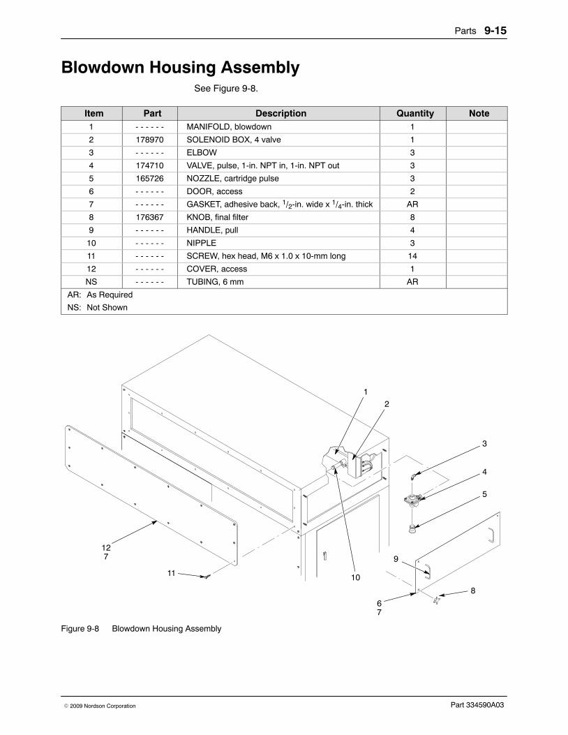
Parts 9-15
Part 334590A03� 2009 Nordson Corporation
Blowdown Housing AssemblySee Figure 9-8.
Item Part Description Quantity Note1 - - - - - - MANIFOLD, blowdown 1
2 178970 SOLENOID BOX, 4 valve 1
3 - - - - - - ELBOW 3
4 174710 VALVE, pulse, 1-in. NPT in, 1-in. NPT out 3
5 165726 NOZZLE, cartridge pulse 3
6 - - - - - - DOOR, access 2
7 - - - - - - GASKET, adhesive back, 1/2-in. wide x 1/4-in. thick AR
8 176367 KNOB, final filter 8
9 - - - - - - HANDLE, pull 4
10 - - - - - - NIPPLE 3
11 - - - - - - SCREW, hex head, M6 x 1.0 x 10-mm long 14
12 - - - - - - COVER, access 1
NS - - - - - - TUBING, 6 mm AR
AR: As Required
NS: Not Shown
3
10
4
5
1
2
9
11
127
67
8
Figure 9-8 Blowdown Housing Assembly

Parts9-16
Part 334590A03 � 2009 Nordson Corporation
Cartridge Filter Housing Assembly See Figure 9-9.
Item Part Description Quantity Note1 - - - - - - NUT, hex, 5/8-11 3
2 - - - - - - WASHER, lock, 5/8 in. 3
3 - - - - - - WASHER, flat, 5/8 in. 3
4 174722 BRACKET, filter centering 3
5 176278 ROD, filter mount, 32 in., Excel 3
6 174723 MOUNT, filter, centering, 36 in. 3
7 156996 FILTER, 36 in., PowderGrid, center mount 3
8 - - - - - - DOOR, assembly, left side 1
9 - - - - - - � LATCH, door 2
NS 1017560 � GASKET, compression, 5/64-in. edge,3/4-in. bulb, C
107 in.
10 - - - - - - DOOR, assembly, right side 1
11 - - - - - - � LATCH, door 2
NS 1017560 � GASKET, compression, 5/64-in. edge,3/4-in. bulb, C
107 in.
NS: Not Shown

Parts 9-17
Part 334590A03� 2009 Nordson Corporation
1
2
3
4
5
6
7
8
9
10
11
Figure 9-9 Cartridge Filter Housing Assembly
Fluid Bed AssemblyPart Description Note
244721 PUMP, powder, transfer, 0.75-in. outlet1016610 PLATE, fluidizing, with strip gasket

Parts9-18
Part 334590A03 � 2009 Nordson Corporation

Options 10-1
Part 334590A03� 2009 Nordson Corporation
Section 10Options
IntroductionThis section contains information about optional equipment for the powderfeed center. Contact your Nordson representative for more informationabout the options listed in this section.
Fluidizing HopperThe fluidizing hopper can be used as an alternative feed source in place ofa standard powder box. The hopper is a plastic box with a fluidizing plate inits base. A hopper lid and cart are available for moving and storing thehopper while it is not being used.
Powder in the hopper is fluidized by compressed air forced through thefluidizing plate. The feed center’s vibratory table and lance assemblyfluidizing air pressure are turned off while the fluidizing hopper is used asthe feed source. The operator enables the hopper fluidizing air pressureand disables the vibratory table and lance assembly fluidizing air bytouching the Select Hopper button on the Auto Menu.
Installation
WARNING: Allow only qualified personnel to perform the following tasks.Follow the safety instructions in this document and all other relateddocumentation.
1. On the Auto Menu, set the Lance/Purge Mode to MANUAL.
2. Touch the LANCE UP button to raise the lance assembly.

Options10-2
Part 334590A03 � 2009 Nordson Corporation
Installation (contd)
3. See Figure 10-1. Loosen the thumb screw (1). Slide the level sensorprobe (4) up until the collar (3) stops against the bottom of the probebracket (2), then tighten the thumb screw.
3
2
4
5
Hopper
Box
1
Figure 10-1 Level Sensor Probe Adjustment
1. Thumb screw2. Probe bracket3. Collar
4. Level sensor probe5. Lance assembly
4. See Figure 10-2. Remove the front box guide (6) by disengaging theclamping levers (5). Set the front box guide aside.
5. Remove the lid and fill the fluidizing hopper (3) 2/3 full of powder.
WARNING: Heavy equipment. Get assistance before trying to lift the fullfluidizing hopper. Failure to observe this caution may result in personalinjury.
6. Set the fluidizing hopper on the vibratory table (7) and slide it backagainst the rear box guide (1). Make sure that the fluidizing hopper iscentered under the lance assembly (2).

Options 10-3
Part 334590A03� 2009 Nordson Corporation
7. Connect 10-mm air tubing between the 10-mm elbow (4) on the hopperand the 10-mm bulkhead fitting (8) on the rear wall of the feed center.
8. Touch the Select Hopper button on the Auto Menu.
9. Use the fluidizing hopper air regulator on the pneumatic panel to set theair pressure to 0.3 bar (5 psi).
10. Start up the system to test fluidizing hopper operation. Allow the powderin the hopper to fluidize for several minutes before coating parts.
1
3
4
5
6
7
2
8
Figure 10-2 Fluidizing Hopper Installation
1. Rear box guide2. Lance assembly3. Fluidizing hopper
4. 10-mm elbow fitting5. Clamping levers6. Front box guide
7. Vibratory table8. 10-mm bulkhead fitting

Options10-4
Part 334590A03 � 2009 Nordson Corporation
Fluidizing Plate Replacement
WARNING: Allow only qualified personnel to perform the following tasks.Follow the safety instructions in this document and all other relateddocumentation.
1. Empty the hopper and vacuum as much powder as possible out of thehopper.
2. See Figure 10-3. Remove the screws (9), flat washers (8) and nuts (7)securing the body (2) to the base (5). Lift the body off the base.
3. Remove the old fluidizing plate (3) and discard it.
4. Inspect the gaskets (4). Replace the gaskets if they are damaged.
5. Vacuum the inside of the base and clean the body and base mountingsurfaces.
NOTE: Make sure that the smooth side of the fluidizing plate is facing up.
6. Set a gasket and the new fluidizing plate on the base.
7. Set the other gasket and the body onto the fluidizing plate.
CAUTION: Do not overtighten the nylon screws. Overtightening the screwswill result in stripped threads and poor hopper performance.
8. Apply removable threadlocking adhesive to the screw threads. Installthe screws, flat washers, and nuts to secure the body to the base.
Fluidizing Hopper Parts See Figure 10-3.
Item Part Description Quantity Note− 7404027 Hopper, fluidizing, feed center 11 — � Lid, hopper 12 — � Body, hopper 13 7404155 � Plate, fluidizing, with gasket, powder feed
center hopper1 B
4 1604476 � � Gasket 2 B5 — � Base, hopper 16 — � Elbow, 1/2 in. NPT x 10 mm tubing 17 7404032 � Nut, hex, M6, Nylon 40 B8 7404031 � Washer, flat, M6, Nylon 80 B9 7404030 � Screw, hex, M6 x 40, Nylon 40 B
NS 1024145 Cart, hopper 1 ANOTE A: The optional cart allows the hopper to be transported easily and slid off the cart directly onto the vibrating
table.
B: These parts included in 1086406 Kit, Service, Fluidizing Hopper, PFC.
NS: Not Shown

Options 10-5
Part 334590A03� 2009 Nordson Corporation
1
2
4
3
4
5
6
7
8
8
9
Figure 10-3 Fluidizing Hopper Parts

Options10-6
Part 334590A03 � 2009 Nordson Corporation
Vibrasonic Sieve ScreenThe Vibrasonic sieve screen increases sieve screen life and powderthroughput in the sieve.
The Vibrasonic system constantly applies an ultrasonic frequency to thesieve screen. The ultrasonic frequency breaks down the surface tension inthe screen, preventing blinding of the sieve screen.
Vibrasonic System ComponentsSee Figure 10-4.
5
7
9
6
4
8
1
2
3
Figure 10-4 Vibrasonic System Components
1. Vibrasonic System control box2. Four-meter control cable3. Support bracket4. Transducer cable5. Sieve deck
6. Vibrasonic transducer7. Sieve screen8. Cap screw9. Vibratory sieve

Options 10-7
Part 334590A03� 2009 Nordson Corporation
Installation
WARNING: Allow only qualified personnel to perform the following tasks.Follow the safety instructions in this document and all other relateddocumentation.
WARNING: Turn off and lock out system electrical power before performingthe following tasks. Failure to observe this warning may result in personalinjury or equipment damage.
NOTE: Inspect all Vibrasonic system components for cleanliness anddamage. Contact your Nordson representative if any components aredamaged.
Vibrasonic Transducer and Sieve Screen InstallationSee Figure 10-4.
1. Clean the sieve screen’s (7) center hub and the bottom of thetransducer (6) with acetone.
NOTE: The transducer must be secured to the flat side of the sievescreen.
2. Set the transducer onto the center hub of the sieve screen. Handtighten the cap screw (8) through the bottom of the sieve screen.
3. Hold the base of the transducer with the supplied pin wrench and turnthe cap screw with the supplied torque wrench until you hear a click.
4. Install the sieve gasket onto the sieve screen.
5. Set the sieve screen into the vibratory sieve (9). Route the transducercable (4) through the sieve deck (5) and clamp the sieve deck onto thevibratory sieve.
Control Box and Cable InstallationSee Figure 10-4.
1. Make sure that the voltage selector on the control box (1) is set to yoursystem’s electrical supply specification.
2. Mount the control box near the pneumatic panel on the powder feedcenter.
3. Connect the four-meter cable (2) to the control box. Route the other endinto the front of the powder feed center.
4. Mount the four-meter cable’s support bracket (3) to the framework onthe inside of the powder feed center. Make sure that the transducercable (4) will be able to reach the support bracket.
5. Connect the transducer cable plug to the four-meter cable plug. Rotatethe transducer cable plug until the location dots on the two plugs align.

Options10-8
Part 334590A03 � 2009 Nordson Corporation
OperationTo turn on the Vibrasonic system, turn the red switch on the control boxclockwise 90 degrees. The POWER and VIBRASONICS indicators on thecontrol box will light. There are five LEDs on the control box door. Duringoperation, LED 1 will light to indicate normal operation.
TroubleshootingThis section contains troubleshooting procedures. These procedures coveronly the most common problems that you may encounter. If you cannotsolve the problem with the information given here, contact your localNordson representative for help.
Fault ConditionsThe LEDs and indicators on the control box indicate faults with theVibrasonic system.
Refer to Table 10-1 for a description of operating conditions indicated by theLEDs and indicators.
Refer to Causes and Corrective Actions to identify and correct errorconditions indicated in Table 10-1.
Table 10-1 LED Functions
Condition POWERIndicator
VIBRASONICSIndicator
LED 1 LED 2 LED 3 LED 4 LED 5
Normal On On On Off Off Off Off
Under Voltage On On or Off Off On Off Off Off
Over Voltage On On Off Off On Off Off
Open Circuit On Flashing Off On Off On Off
Short Circuit On On Off On Off Off On

Options 10-9
Part 334590A03� 2009 Nordson Corporation
Causes and Corrective ActionsUse the following chart to correct faults conditions indicated by the LEDs.
Problem Possible Cause Corrective Action
1. Under voltage (outputvoltage too low)
Supply voltage too low Increase the supply voltage.
Sieve screen center hub bondingdamaged
Replace the sieve screen.
Damaged generator Contact the Vibrasonic systemmanufacturer.
2. Over voltage (outputof generator too high)
Poor contact surfaces betweentransducer and sieve screen
Remove the transducer from thescreen and clean the mating surfaceswith acetone. Assemble thetransducer to the screen using theVibrasonic Transducer and SieveScreen Installation procedure.
Loose transducer Tighten the transducer using thesupplied torque wrench. Refer to theVibrasonic Transducer and SieveScreen Installation procedure.
Damaged sieve screen matingsurface
Replace the sieve screen.
Damaged transducer matingsurface
Replace the transducer.
3. Open circuit (opencircuit in output fromcontrol box)
Disconnected transducer cable Check the transducer cableconnections.
Damaged four-meter cable orconnector
Replace the four-meter cable.
Loose or damaged wiring in thecontrol box
Check the control box wiring.Tighten any loose connections.
Damaged transducer Replace the transducer.
4. Short circuit (shortcircuit in output fromcontrol box)
Short circuit in four-meter cable Replace the four-meter cable.
Short circuit in either four-meter ortransducer cable connectors
Thoroughly clean the connectors.
Short circuit in transducer Replace the transducer.
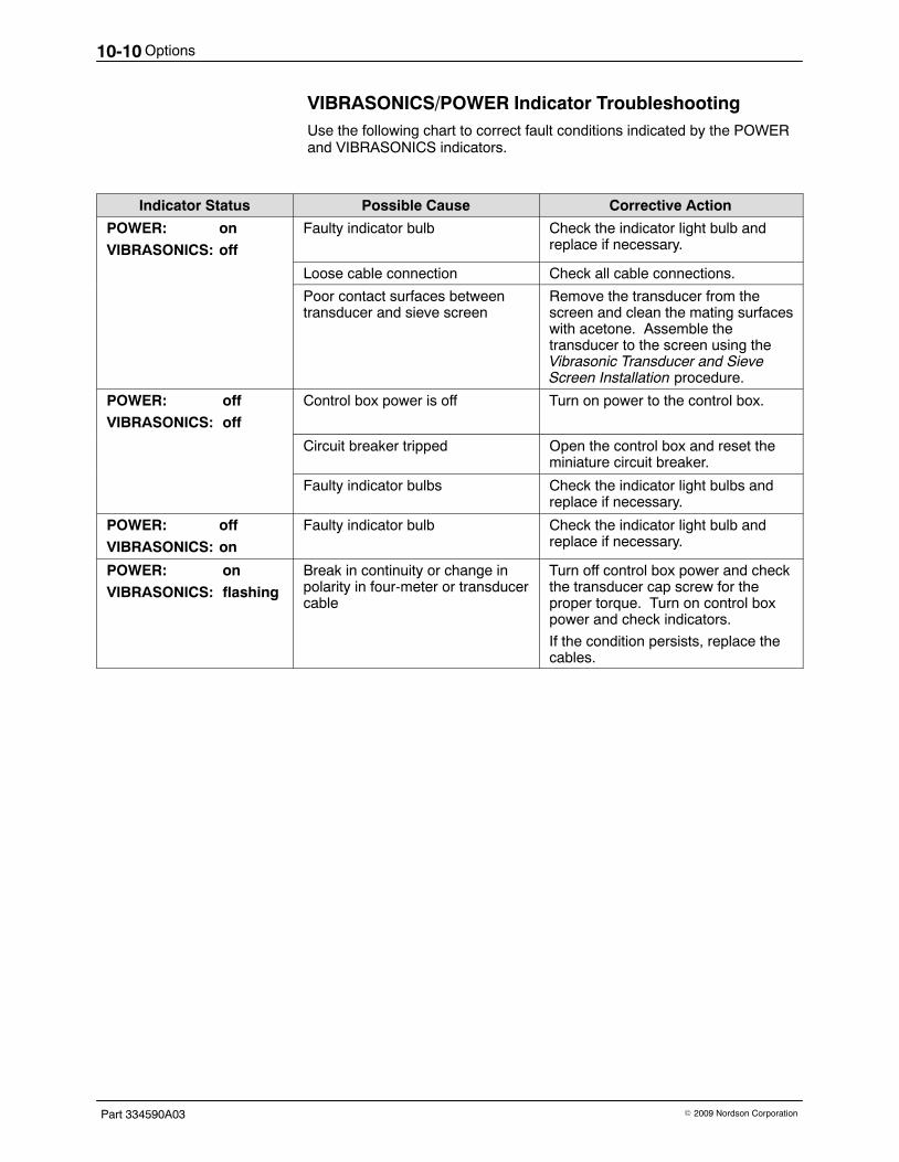
Options10-10
Part 334590A03 � 2009 Nordson Corporation
VIBRASONICS/POWER Indicator TroubleshootingUse the following chart to correct fault conditions indicated by the POWERand VIBRASONICS indicators.
Indicator Status Possible Cause Corrective Action
POWER: on
VIBRASONICS: off
Faulty indicator bulb Check the indicator light bulb andreplace if necessary.
Loose cable connection Check all cable connections.
Poor contact surfaces betweentransducer and sieve screen
Remove the transducer from thescreen and clean the mating surfaceswith acetone. Assemble thetransducer to the screen using theVibrasonic Transducer and SieveScreen Installation procedure.
POWER: off
VIBRASONICS: off
Control box power is off Turn on power to the control box.
Circuit breaker tripped Open the control box and reset theminiature circuit breaker.
Faulty indicator bulbs Check the indicator light bulbs andreplace if necessary.
POWER: off
VIBRASONICS: on
Faulty indicator bulb Check the indicator light bulb andreplace if necessary.
POWER: on
VIBRASONICS: flashing
Break in continuity or change inpolarity in four-meter or transducercable
Turn off control box power and checkthe transducer cap screw for theproper torque. Turn on control boxpower and check indicators.
If the condition persists, replace thecables.

Options 10-11
Part 334590A03� 2009 Nordson Corporation
Vibrasonic System PartsSee Figure 10-5.
Item Part Description Quantity Note— 1014564 SYSTEM, Vibrasonic 1
1 - - - - - - � BOX, control, Vibrasonic 1
2 - - - - - - � CABLE, 4-meter, with support bracket 1
3 - - - - - - � CABLE, transducer 1
4 - - - - - - � TRANSDUCER, Vibrasonic 1
5 1014565 � SCREEN, Vibrasonic, 100 mesh, with gasket 1 A
6 - - - - - - � SCREW, cap, socket head, M8 1
NOTE A: Other mesh sizes are available. Contact your Nordson representative for more information.
5
4
3
6
1
2
Figure 10-5 Vibrasonic System Parts
Options10-12
Part 334590A03 � 2009 Nordson Corporation