potential of porous medium combustion technology as ... · potential of porous medium combustion...
TRANSCRIPT
Potential of porous medium combustion technology as applied to internal combustion engines
Prof.Dr.-Ing. Miroslaw Weclas
Institut für Fahrzeugtechnik
Georg-Simon-Ohm-Fachhochschule Nürnberg
Keßlerplatz 12
D-90489 Nürnberg
Abstract
The paper describes application of a highly porous
open cell structures to internal combustion engines
for supporting mixture formation and combustion
processes. Porous structures, materials and their
properties for engine application are discussed in
this paper. Especially application to a high tempera-
ture combustion processes are considered.
Novel concepts for internal combustion engines
based on the application of porous medium
technology are presented and discussed. The main
attention is focused on the engine concepts having
potential for homogeneous (nerly emissions free)
combustion process under variable engine
operational conditions. It is shown that porous
media can be used for a great variety of
improvements in the combustion process. The key
role for NOx reduction and soot emission
ellimination is a homogeneous combustion in
engine. This can be realised by homogeneous
mixture formation, and a 3D ignition preventing from
formation of a flame front having a temperature
gradient a in the entire combustion volume. All
these processes: gas flow, fuel injection and its
spatial distribution, vaporization, mixture
homogenization, ignition and combustion can be
controlled or positively influenced with the help of
porous media/ceramic reactors.
ISSN 1616-0762 Sonderdruck Schriftenreihe der Georg-Simon-Ohm-Fachhochschule Nürnberg Nr. 32


Schriftenreihe Georg-Simon-Ohm-Fachhochschule Nürnberg Seite 3
Potential of porous medium (PM) combustion technology as applied to internal combustion engines
1. Actual problems of mixture formation and combustion in internal combustion engines
Future internal combustion (IC) engine will be characterized by a (nearly-) zero emissions level (for both gaseous and particulate matter components) under possible lowest fuel consumption permitted at all operational conditions. This may be achieved by realization of homogeneous combustion process in engine. An internal combustion engine (especially for road vehicle application) has to operate in a wide range of loads and speeds. From the point of view of reduction of combustion emissions and fuel consumption, especially attractive would be application of lean homogeneous charges for operation at engine part loads. There are different technologies available for reduction of engine emissions (e.g. electronically controlled high pressure injection systems, variable valve controlling, EGR, etc), however, a simple combination of them does not automatically solve the problem of engine emissions under all operational conditions. In author opinion, however, these technologies may be utilized in new concepts for mixture formation and combustion that are necessary to be created in the nearest future for “clean reciprocating engine”. While future IC engines require low specific fuel consumption under (near-) zero combustion emissions level, it will be necessary to significantly change a primary combustion process in conventional engines, e.g. by application of porous medium technology. New approaches using porous medium (PM) technology are described in this paper.
2. Porous medium technology
2.1. Introduction to porous medium
technology
In this paper a highly porous structures having open cells are considered, with porosity higher than 80%, and typically higher than 90%. This makes the porous media transparent for gas flow, spray and flame (Fig.1). Porous medium (PM) technology is here defined as an utilization of specific and unique features of highly porous medium for supporting of individual processes (mixture formation, ignition and combustion) realized in engine (see Fig.2) [1, 2]. Most of these processes perform in PM-volume
drastically different manner from this observed in a free volume.
Figure 1: Reconstructed 3D-structure of SiC foam on the basis of
computer tomography (10mm x 10mm x 10mm probe)
Selected features of the porous medium permit its attractive application to the following engine processes:
Energy recirculation in engine cycle in the form of hot burned gases recirculation or combustion energy: this may significantly influence thermodynamic properties of the charge in the cylinder and may control the ignitability (activity) of the charge. This energy recirculation may be performed under different pressure and temperature conditions during the engine cycle. Additionally, this heat recuperation may be used for controlling the combustion temperature level.
Figure 2: Main features of porous structures to be utilized to support
engine processes
Fuel injection in PM-volume: especially unique features of liquid jet distribution and homogenization throughout the PM-volume (effect of multi-jet splitting) [3] is very attractive for fast mixture formation in the PM-volume.
Large specificsurface area
Variabilitystructure, density,
geometry
High thermalstability
High mechanicalstability
Surfaceproperties
Excellent heattransfer
Large heatcapacity
Large porosity
Schriftenreihe Georg-Simon-Ohm-Fachhochschule Nürnberg Seite 4
Potential of porous medium (PM) combustion technology as applied to internal combustion engines
Fuel vaporization in PM-volume: combination of large heat capacity of the PM-material, large specific surface area with excellent heat transfer in PM-volume make the liquid fuel vaporization very fast and complete. Here two different conditions of the process have to be considered: vaporization with presence and with lack of oxygen.
Mixing and homogenization in PM-volume: unique features of the flow properties inside 3D-structures allow very effective mixing and homogenization in PM-volume.
3D-thermal-PM-ignition (if PM temperature is at least equal to ignition temperature under certain thermodynamic properties and mixture composition): there is a new kind of ignition, especially effective if the PM-volume creates automatically the combustion chamber volume [4, 5].
Heat release in PM-volume under controlled combustion temperature (properties of homogeneous combustion): there is only one known kind of combustion, that permits homogeneous combustion conditions almost independently of the engine load with possibility of controlling of the combustion temperature level [4, 5].
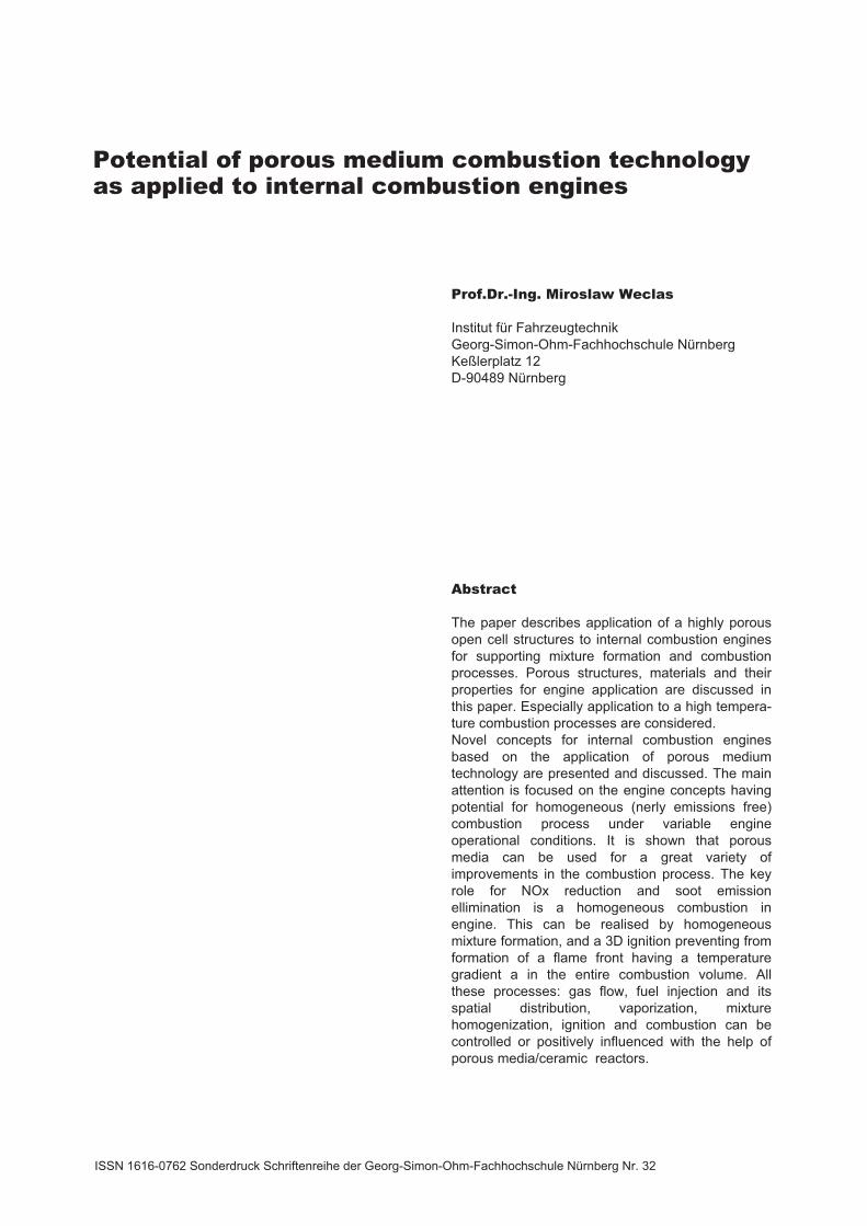
Depending on the application of a porous medium, a combination of thermal and mechanical properties of the materials as well as their inner structure and pores size have to separately be chosen and optimized for supporting of particular engine process. If the porous medium is used directly for controlling the combustion process under high pressure conditions, above requirements become especially critical. The probe presented in figure 1 is characterized by the following parameters: porosity=91,88%, connection density =0.0311 per mm3 (represents a number of connections or junctions per cubic millimetre) - see Fig. 3. For applications considered in this paper typical pore size is higher than 1mm, and usually is of order of 3mm large. This pore size is often expressed by the pore density “ppi” – pore per linear inch. Typical pore density useful for applications reported in this paper is from 8 to 30ppi. The pore shape and pore density depends on the basic foam used for manufacturing of final foams (e.g. PU-foam for ceramic foams).
Figure 3: Thickness distribution of pore walls (top) and of pore size
(bottom) of the SiC foam of figure 1.
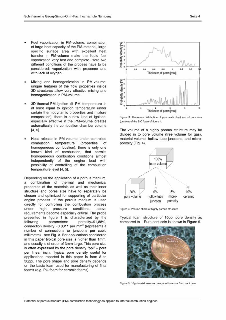
The volume of a highly porous structure may be divided in to pore volume (free volume for gas), material volume, hollow tube junctions, and micro-porosity (Fig. 4).
Figure 4: Volume share of highly porous structure
Typical foam structure of 10ppi pore density as compared to 1 Euro cent coin is shown in Figure 5.
Figure 5: 10ppi metal foam as compared to a one Euro cent coin
100%
foam volume
80%
pore volume
5%
hollow tube
junction
5%
micro-
porosity
10%
ceramic

Schriftenreihe Georg-Simon-Ohm-Fachhochschule Nürnberg Seite 5
Potential of porous medium (PM) combustion technology as applied to internal combustion engines
This high porosity of the porous material significantly influences the density of the structure. In Figure 6 are compared densities of steel, SiC-ceramic and SiC-foam. Additionally, this figure shows the effect of pore density on the specific surface area.
Figure 6: Density (top) and specific surface area (bottom) of highly
porous 3D-structure
More imagination on the pore density and corresponding pore size for ceramic foam (SiC) is given in Figure 7.
Figure 7: Examples of different pore densities for SiC foam
The variability of structures, materials and pores size is shown in figure 8, where ceramic foam structure, static mixer as well as wire packing are presented.
Figure 8: Examples of different porous structures
2.2. Selection of available PM materials and their features in application to engine processes
As already indicated in this section, there are number of important parameters that have to be considered in selection of PM materials for application to combustion processes realized in porous media. On one hand side, features of PM that are directly related to the heat transfer and combustion process are very important, e.g. specific surface area, heat transport properties, heat capacity and transparency for fluid flow and flame propagation. On the other hand, the thermal resistance and the mechanical properties of PM structure under high pressures are important for particular applications (see Table 1). Another parameter which must also be considered is the pores structure. Generally, the most important parameters of PM for application to combustion technology in can be selected as follows:
specific surface area heat transport properties heat capacity transparency for fluid flow and flame pores size, pores density and pores structure thermal resistance

Schriftenreihe Georg-Simon-Ohm-Fachhochschule Nürnberg Seite 6
Potential of porous medium (PM) combustion technology as applied to internal combustion engines
mechanical resistance and mechanical properties under heating-cooling conditions
PM material surface properties. Electrical properties
Table 1: Basic features and requirements of porous materials in
application to engines
Parameters Range of values (required/expected)
Specific surface area
Large: must be adopted to particular application to
support individual processes
Heat transport properties
Excellent: especially important for PM-engine concept and
homogeneity of the combustion zone
Heat capacity Large: Must be adopted to particular application. In
case of PM-engine defines the engine dynamic
properties and influences the cycle
thermodynamics. Also influences cold-start
conditions
Permeability to flow and flame propagation
High porosity: For gas or liquid flow more than 80% porosity;
preferably more than 90% porosity with open
pores (cells). Pore size influences different
processes in PM volume.
Pore size and size distribution
Typical pore density from 8ppi to 30ppi: For flame propagation under pressure see
Pecklet number criterion. Directly influence
pressure losses, multi-jet splitting by injection,
homogenization in the volume
Pore shape Principally all available shapes are suitable Cells must be open
Thermal shock resistance
High: Especially for PM-engine concept. Depending
on the reactor location and art of montage in
engine components
Corrosion resistance
High: especially in the atmosphere of burned gases
Electrical properties
For direct heating: high electrical resistance and homogeneous
energy distribution (preferably voltage 12V and
current 10 to 80A). Reachable temperatures are
of 1500K. Could be important for cold-start
conditions.
Available maximum temperature
Depends on the application: PM-engine concept Tmax < 2000K; MDI concept
Tmax <1500K; Two-stage combustion concept
Tmax < 1800K
Porous medium mechanical stability
Important under high temperature and pressure conditions: Very critical factor in the case of ceramic
material mounted in the piston top.
Accelerations up to 500 of earth acceleration
are typical and large temperature gradients are
usual
Porous medium montage in engine components
Very critical: especially in the case of ceramic materials.
Possible gluing using a high temperature
ceramic glues. Important is also that the porous
reactor ones is cold and once may be very hot.
Metal foams could be more useful if their
application temperature would be high enough
Variable geometry Important: for all engine applications (adopting to available
space and shape)
Long time stability Should be very high: This is still almost unknown area for engine
applications.
Large inner surface area Owing to large inner surface area, the porous material permits the enlargement of the reaction zone owing to very effective heat transport between the gas phase and the porous medium. Additionally, this large specific surface area (of the order of 102 - 104 m-1) prefers the medium to be applied as a vaporizer and heat exchanger. This inner surface area depends on the pore density, its geometry and the basic structure used for manufacturing of PM (see Fig. 9).
Figure 9: Specific surface area versus pore density for metal foam
structures (acc. to Porvair Advanced Materials, USA)
For example, for metal foam made of Ni-Cr-Al the specific surface area (according to the mean pore diameter dmean) for dmean=0.9mm is 1700 m-1, for

Schriftenreihe Georg-Simon-Ohm-Fachhochschule Nürnberg Seite 7
Potential of porous medium (PM) combustion technology as applied to internal combustion engines
dmean=1.4mm, the specific surface area is 1000 m-1,and for dmean=2.3mm is 500 m-1.
Very effective heat transport propertiesHeat transport properties of PM are characterized by efficient heat conductivity and very effective heat radiation inside PM (see Fig.10). These excellent heat transport properties permit for combustion in porous medium much higher combustion rates than for a free flame (approximately 10 to 20 times higher). Additionally, there is strong cooling of the reaction zone and in consequence the thermal NOx
formation is significantly reduced (low-temperature combustion).
Figure 10: Comparison of emissivity for gas and for 3D-PM structure
Basic mechanisms for heat transfer in porous medium are selected in Table.2.
Table 2: Basic mechanisms for heat transfer in PM
Art of heat transfer in
PM Description and characterization
conduction Heat transfer by conduction takes place using atomic and molecular interactions in the material and is based on Fourier’s law:
f s = heat conductivity (fluid “f” and solid “s”)
convection The convective heat transfer depends on the flow field, temperature field, heat capacity and the enthalpy of mixture. For description of convective heat transfer, a Newton’s law may be applied:
q = heat flow flux perpendicular to the wall,
Tf = fluid temperature, Tw = wall temperature,
= heat transmission coefficient
Radiation The surface-related heat flow, which is radiated by body into the half space, is given by
4sTEq
E = emissivity coefficient, = Stefan-Boltzmann, Ts =
solid body temperature
Part of the heat released during the combustion process is „accumulated inside” the porous material resulting in a high temperature of the solid phase surface (see Fig.11).
Figure 11: Example of flat PM-burner indicating strong heat radiation
of the solid phase (SiC foam, T~1500K)
Large porosity and low pressure lossesAs already indicated, highly porous materials mean structures of porosity over approx. 80%. Owing to this large porosity, the PM materials are transparent for gas and liquid flows as well as for flames. This transparency permits low pressure losses in fluid (gas) flow through the PM volume. Pressure drop over the wire packing versus bulk velocity for three different PM lengths (50,100 and 150mm for constant packing density is shown in Figure 12.
Figure 12: Pressure drop over the wire packing versus bulk velocity
for three different PM lengths
L=50mm
L=100mm
L=150mm
Wire diameter 0.28mm L=50mm
L=100mm
L=150mm
Wire diameter 0.28mm
Mean bulk velocity [m/s]
Pre
ssur
edr
op [P
a]
Schriftenreihe Georg-Simon-Ohm-Fachhochschule Nürnberg Seite 8
Potential of porous medium (PM) combustion technology as applied to internal combustion engines
Example of pressure losses measured for ceramic foam and different pore densities is given in Figure 13.
Figure 13: Pressure drop over the ceramic foams of different pore
densities (ppi)
PM materials Typical ceramic materials being of interest in application to PM-combustion technology are (see Fig.8): oxidides (e.g. Al2O3, ZrO2), and non-oxides (e.g. SiC). The cells of ceramic foam can be idealized as a pentagonal dodecahedron (Fig.14). The edges of the dodecahedron are the struts of the ceramic foam. In the case of flowing gas through the foams, the flow is forced to separate and reattach at the struts, resulting in a good mixing and strong interaction between flowing gas and the PM material.
Figure 14: Structure of PU-Structure (left), SiC foam structure (right)
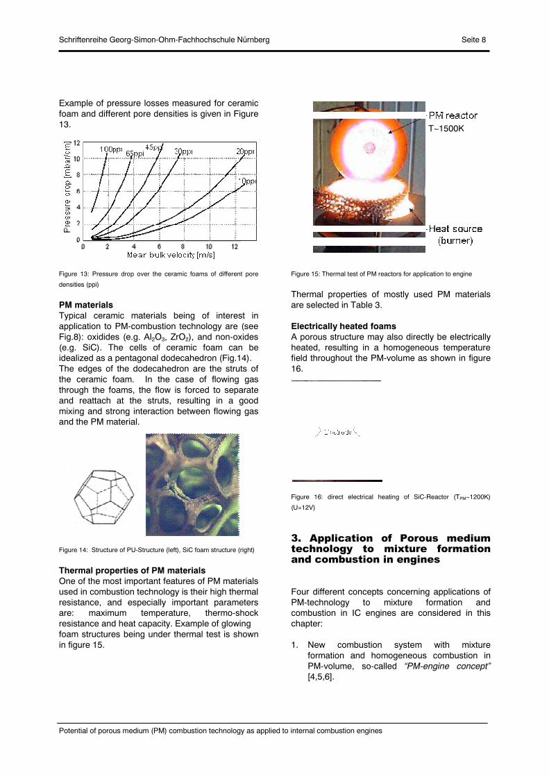
Thermal properties of PM materialsOne of the most important features of PM materials used in combustion technology is their high thermal resistance, and especially important parameters are: maximum temperature, thermo-shock resistance and heat capacity. Example of glowingfoam structures being under thermal test is shown in figure 15.
Figure 15: Thermal test of PM reactors for application to engine
Thermal properties of mostly used PM materials are selected in Table 3.
Electrically heated foamsA porous structure may also directly be electrically heated, resulting in a homogeneous temperature field throughout the PM-volume as shown in figure 16.
Figure 16: direct electrical heating of SiC-Reactor (TPM~1200K)
(U=12V)
3. Application of Porous medium technology to mixture formation and combustion in engines
Four different concepts concerning applications of PM-technology to mixture formation and combustion in IC engines are considered in this chapter:
1. New combustion system with mixture formation and homogeneous combustion in PM-volume, so-called “PM-engine concept” [4,5,6].
T~1500K
Schriftenreihe Georg-Simon-Ohm-Fachhochschule Nürnberg Seite 9
Potential of porous medium (PM) combustion technology as applied to internal combustion engines
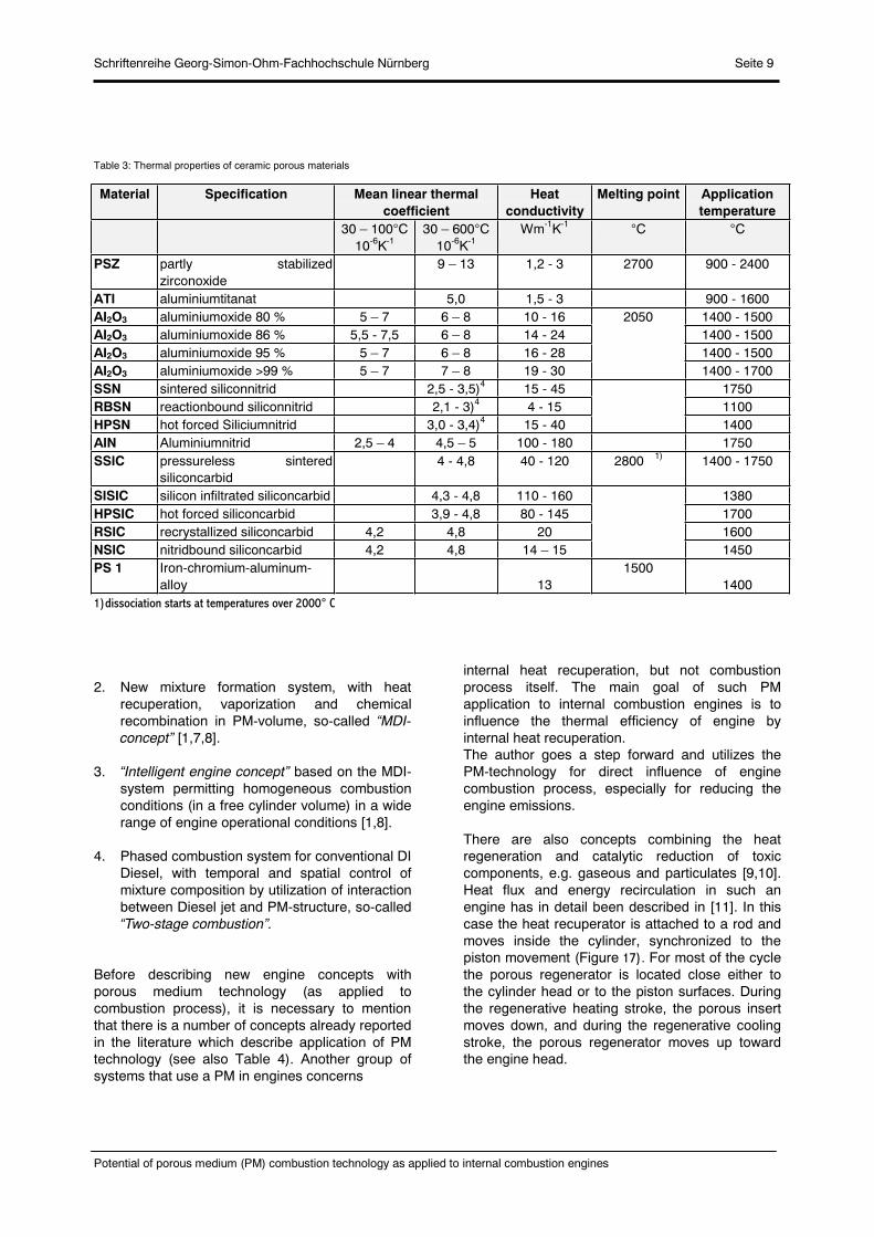
Table 3: Thermal properties of ceramic porous materials
1)dissociation starts at temperatures over 2000° C
2. New mixture formation system, with heat recuperation, vaporization and chemical recombination in PM-volume, so-called “MDI-concept” [1,7,8].
3. “Intelligent engine concept” based on the MDI-system permitting homogeneous combustion conditions (in a free cylinder volume) in a wide range of engine operational conditions [1,8].
4. Phased combustion system for conventional DI Diesel, with temporal and spatial control of mixture composition by utilization of interaction between Diesel jet and PM-structure, so-called “Two-stage combustion”.
Before describing new engine concepts with porous medium technology (as applied to combustion process), it is necessary to mention that there is a number of concepts already reported in the literature which describe application of PM technology (see also Table 4). Another group of systems that use a PM in engines concerns
internal heat recuperation, but not combustion process itself. The main goal of such PM application to internal combustion engines is to influence the thermal efficiency of engine by internal heat recuperation. The author goes a step forward and utilizes the PM-technology for direct influence of engine combustion process, especially for reducing the engine emissions.
There are also concepts combining the heat regeneration and catalytic reduction of toxic components, e.g. gaseous and particulates [9,10]. Heat flux and energy recirculation in such an engine has in detail been described in [11]. In this case the heat recuperator is attached to a rod and moves inside the cylinder, synchronized to the piston movement (Figure 17). For most of the cycle the porous regenerator is located close either to the cylinder head or to the piston surfaces. During the regenerative heating stroke, the porous insert moves down, and during the regenerative cooling stroke, the porous regenerator moves up toward the engine head.
Material Specification Mean linear thermal coefficient
Heat conductivity
Melting point Application temperature
30 – 100°C 10-6K-1
30 – 600°C 10-6K-1
Wm-1K-1 °C °C
PSZ partly stabilizedzirconoxide
9 – 13 1,2 - 3 2700 900 - 2400
ATI aluminiumtitanat 5,0 1,5 - 3 900 - 1600 AI2O3 aluminiumoxide 80 % 5 – 7 6 – 8 10 - 16 2050 1400 - 1500 AI2O3 aluminiumoxide 86 % 5,5 - 7,5 6 – 8 14 - 24 1400 - 1500 AI2O3 aluminiumoxide 95 % 5 – 7 6 – 8 16 - 28 1400 - 1500 AI2O3 aluminiumoxide >99 % 5 – 7 7 – 8 19 - 30 1400 - 1700 SSN sintered siliconnitrid 2,5 - 3,5)4 15 - 45 1750 RBSN reactionbound siliconnitrid 2,1 - 3)4 4 - 15 1100 HPSN hot forced Siliciumnitrid 3,0 - 3,4)4 15 - 40 1400 AIN Aluminiumnitrid 2,5 – 4 4,5 – 5 100 - 180 1750 SSIC pressureless sintered
siliconcarbid 4 - 4,8 40 - 120 2800 1) 1400 - 1750
SISIC silicon infiltrated siliconcarbid 4,3 - 4,8 110 - 160 1380 HPSIC hot forced siliconcarbid 3,9 - 4,8 80 - 145 1700 RSIC recrystallized siliconcarbid 4,2 4,8 20 1600 NSIC nitridbound siliconcarbid 4,2 4,8 14 – 15 1450 PS 1 Iron-chromium-aluminum-
alloy
131500
1400
Schriftenreihe Georg-Simon-Ohm-Fachhochschule Nürnberg Seite 10
Potential of porous medium (PM) combustion technology as applied to internal combustion engines
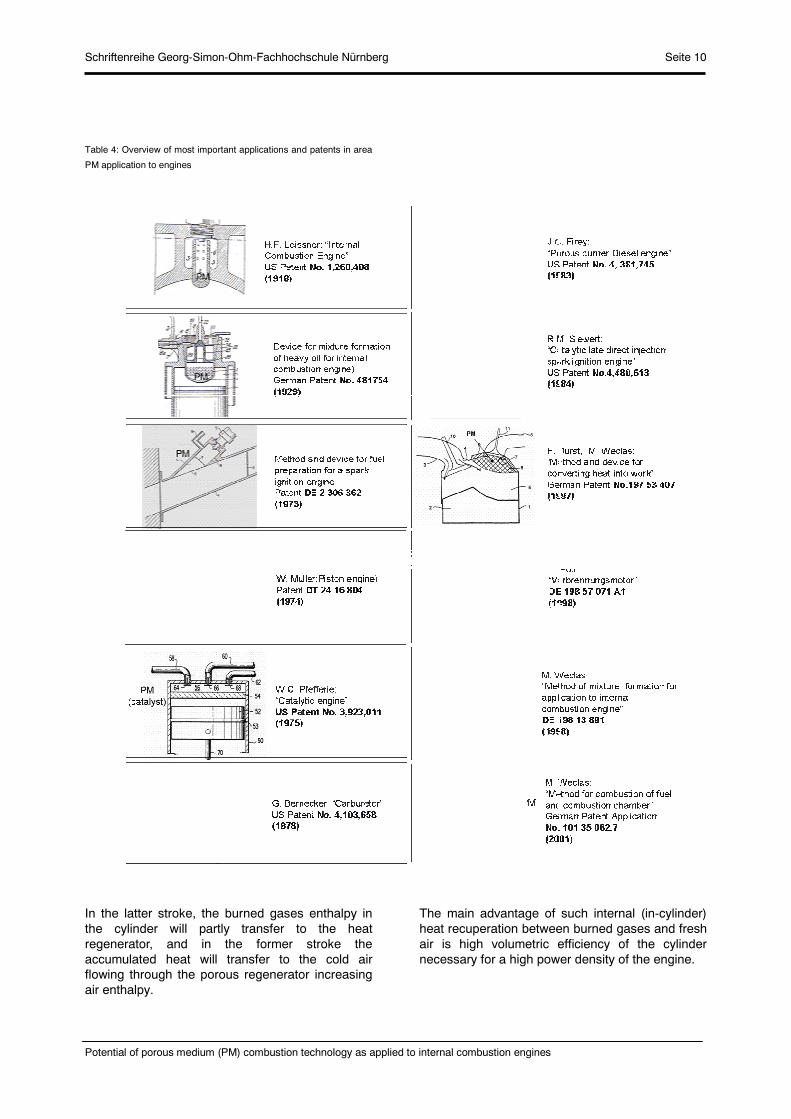
Table 4: Overview of most important applications and patents in area
PM application to engines
In the latter stroke, the burned gases enthalpy in the cylinder will partly transfer to the heat regenerator, and in the former stroke the accumulated heat will transfer to the cold air flowing through the porous regenerator increasing air enthalpy.
The main advantage of such internal (in-cylinder) heat recuperation between burned gases and fresh air is high volumetric efficiency of the cylinder necessary for a high power density of the engine.
Schriftenreihe Georg-Simon-Ohm-Fachhochschule Nürnberg Seite 11
Potential of porous medium (PM) combustion technology as applied to internal combustion engines
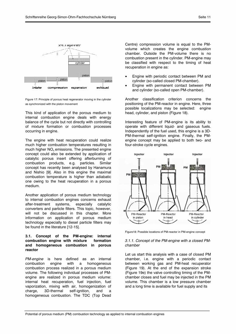
Figure 17: Principle of porous heat regenerator moving in the cylinder
as synchronized with the piston movement
This kind of application of the porous medium to internal combustion engine deals with energy balance of the cycle but not directly with controlling of mixture formation or combustion processes occurring in engine.
The engine with heat recuperation could realize much higher combustion temperatures resulting in much higher NOx emissions. The presented engine concept could also be extended by application of catalytic porous insert offering afterburning of combustion products, e.g. particles. Similar concept has recently been analysed by Hanamura and Nishio [9]. Also in this engine the maximal combustion temperature is higher than adiabatic one owing to the heat recuperation in a porous medium.
Another application of porous medium technology to internal combustion engines concerns exhaust after-treatment systems, especially catalytic converters and particle filters. This topic, however, will not be discussed in this chapter. More information on application of porous medium technology especially to diesel particle filters may be found in the literature [12-15].
3.1. Concept of the PM-engine: internal combustion engine with mixture formation and homogeneous combustion in porous reactor
PM-engine is here defined as an internal combustion engine with a homogeneous combustion process realized in a porous medium volume. The following individual processes of PM-engine are realized in porous medium volume: internal heat recuperation, fuel injection, fuel vaporization, mixing with air, homogenization of charge, 3D-thermal self-ignition, and a homogeneous combustion. The TDC (Top Dead
Centre) compression volume is equal to the PM-volume which creates the engine combustion chamber. Outside the PM-volume there is no combustion present in the cylinder. PM-engine may be classified with respect to the timing of heat recuperation in engine as:
Engine with periodic contact between PM and cylinder (so-called closed PM-chamber).
Engine with permanent contact between PM and cylinder (so-called open PM-chamber).
Another classification criterion concerns the positioning of the PM-reactor in engine. Here, three possible localizations may be selected: engine head, cylinder, and piston (Figure 18).
Interesting feature of PM-engine is its ability to operate with different liquid- and gaseous fuels. Independently of the fuel used, this engine is a 3D-PM-thermal self-ignition engine. Finally, the PM-engine concept may be applied to both two- and four-stroke cycle engines.
Figure18: Possible locations of PM-reactor in PM-engine concept
3.1.1. Concept of the PM-engine with a closed PM-chamber
Let us start this analysis with a case of closed PM chamber, i.e. engine with a periodic contact between working gas and PM-heat recuperator (Figure 19). At the end of the expansion stroke (Figure 19e) the valve controlling timing of the PM-chamber closes and fuel may be injected in the PM volume. This chamber is a low pressure chamber and a long time is available for fuel supply and its

Schriftenreihe Georg-Simon-Ohm-Fachhochschule Nürnberg Seite 12
Potential of porous medium (PM) combustion technology as applied to internal combustion engines
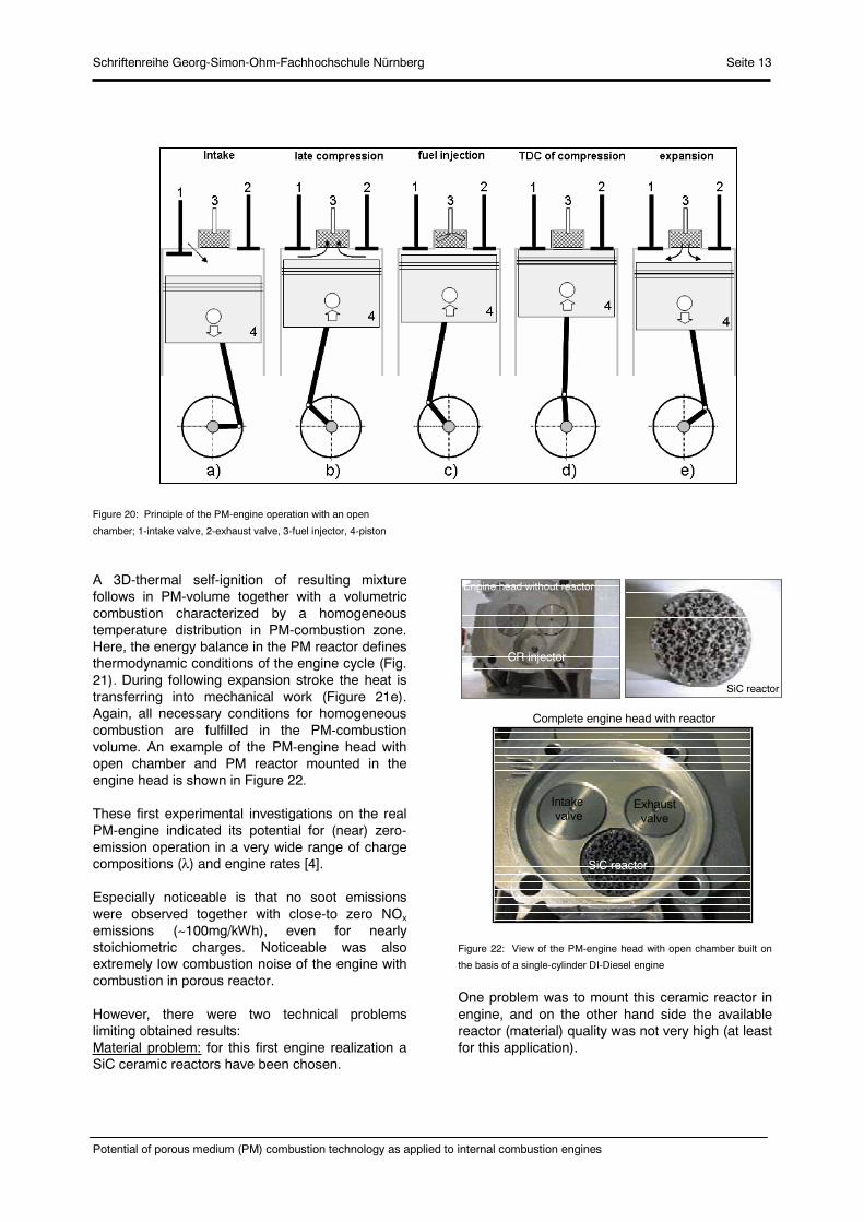
Figure 19: Principle of the PM-engine operation with a closed
chamber; 1-intake valve, 2-exhaust valve, 3-PM-chamber valve, 4-
fuel injector, 5-piston
vaporization in the PM-volume. Simultaneously, other processes may perform in the cylinder volume. These processes may be continued through exhaust, intake and compression strokes (Figure 19a).Near the TDC of compression (Figure 19b) the valve in PM-chamber opens and the compressed air flows from the cylinder to the hot PM containing fuel vapours. Very fast mixing of both gases occurs before mixture igniting in the whole PM-volume (Figure 19c). The resulting heat release process performs simultaneously in the whole PM volume. Three necessary conditions for a homogeneous combustion are here fulfilled: homogenization of charge in PM-volume, 3D-thermal self-ignition in PM-volume and a volumetric combustion with a homogeneous temperature field in PM-volume. Additionally, the PM deals as a heat capacitor and controls the combustion temperature level
3.1.2. Concept of the PM-engine with an open PM-chamber
Another possible realization of the PM-engine is a combustion system characterized by a permanent contact between working gas and PM-reactor. In this case it is assumed that the PM-combustion chamber is mounted in the engine head, as shown in Figure 20. During the intake stroke it is weak
influence of the PM-heat capacitor on the in-cylinder air thermodynamic conditions (Fig.20a). Also during early compression stroke, only small amount of air contact the hot PM. This heat exchange process (non-adiabatic compression) increases with continuing compression timing (Figure 20b), and at the TDC the whole combustion air is closed in the PM volume. Near the TDC of compression the fuel is injected into PM volume (Figure 20c) and very fast fuel vaporization and mixing with air occur in 3D-structure of PM.
Figure 21: Energy balance of PM-reactor in PM-engine with open
chamber: E1=energy supplied from compression; E2=energy
supplied with fuel; E3=energy losses; E4=energy supplied from PM to
the air; E5=energy transported with burned gases
PM-Reactor
E1
E2 E3
E4
E5
PM-ReactorPM-Reactor
E1
E2 E3
E4
E5
PM-Reactor
Schriftenreihe Georg-Simon-Ohm-Fachhochschule Nürnberg Seite 13
Potential of porous medium (PM) combustion technology as applied to internal combustion engines
Figure 20: Principle of the PM-engine operation with an open
chamber; 1-intake valve, 2-exhaust valve, 3-fuel injector, 4-piston
A 3D-thermal self-ignition of resulting mixture follows in PM-volume together with a volumetric combustion characterized by a homogeneous temperature distribution in PM-combustion zone. Here, the energy balance in the PM reactor defines thermodynamic conditions of the engine cycle (Fig. 21). During following expansion stroke the heat is transferring into mechanical work (Figure 21e). Again, all necessary conditions for homogeneous combustion are fulfilled in the PM-combustion volume. An example of the PM-engine head with open chamber and PM reactor mounted in the engine head is shown in Figure 22.
These first experimental investigations on the real PM-engine indicated its potential for (near) zero-emission operation in a very wide range of charge compositions ( ) and engine rates [4].
Especially noticeable is that no soot emissions were observed together with close-to zero NOx
emissions (~100mg/kWh), even for nearly stoichiometric charges. Noticeable was also extremely low combustion noise of the engine with combustion in porous reactor.
However, there were two technical problems limiting obtained results: Material problem: for this first engine realization a SiC ceramic reactors have been chosen.
Figure 22: View of the PM-engine head with open chamber built on
the basis of a single-cylinder DI-Diesel engine
One problem was to mount this ceramic reactor in engine, and on the other hand side the available reactor (material) quality was not very high (at least for this application).
Engine head without reactor
Complete engine head with reactor
CR injector
SiC reactor
Intakevalve
Exhaustvalve
SiC reactor

Schriftenreihe Georg-Simon-Ohm-Fachhochschule Nürnberg Seite 14
Potential of porous medium (PM) combustion technology as applied to internal combustion engines
Control of reactor temperature: the experiments have shown that the engine operation according to the PM-engine principle was only possible if required PM temperature has been achieved at the beginning of engine operation.
If PM-reactor temperature was too low, a low temperature oxidation performed in the PM-volume, and free volume afterburning late in the expansion phase has been observed in the cylinder. Of course, in this case the system could not work according to the PM-engine principle, despite of PM reactor built in the engine. A strong after-burning in the cylinder was then observed in part of the experimental investigations. The author wants to indicate that further development of the PM-engine concept requires, besides material development, basic research on low- and high-temperature oxidation processes in PM-reactor under pressure and on the transition between both reactions. It will be necessary to recognize the proper operational conditions for combustion in PM-reactor as suggested in Fig. 23. For this reason the author proposes to use a constant volume high pressure chamber simulating TDC of compression in PM-engine concept. In this case an electrically heating reactor allows setting the chamber (reactor) pressure independently of its temperature for different charge compositions.
Figure 23: Sill not well recognized combustion modes in porous
reactor under pressure
3.2. Concept of MDI-engine: intelligent engine concept with application of PM-chamber for mixture formation
MDI (Mixture Direct Injection) concept describes mixture formation and heat recuperation system. This concept offers homogenization of the combustion process by performing fuel
vaporization, its chemical recombination (low temperature oxidation processes, e.g. cool- and blue-flames) and energy recirculation in a porous medium chamber. The enthalpy of the burned gases is partly transferred to the porous medium and can later be supplied back to the cylinder. This energy is utilized for both vaporization of liquid fuel and for its chemical recombination in the PM-volume [1,8].
A practical realization of the MDI system requires a porous medium chamber to be mounted in proximity to the cylinder and equipped with a valve (in this paper a poppet valve is considered – see Fig. 24) permitting contact between PM-chamber and the cylinder volume. The engine cycle described below, models the real engine cycle, and other than presented timings for PM-chamber may be used. MDI concept may be combined with conventional combustion modes, such as GDI (Gasoline Direct Injection), HCCI (Homogeneous Charge Compression Ignition) [16-19] and with radical combustion, and only control of the PM-chamber timing is necessary to select a combustion mode used in the engine [8]. By applying the variable timing of the PM-chamber, a MDI concept offers combination of individual combustion modes in one engine, as described
Figure 24: Principle of MDI system design and intelligent engine
below. Characteristic phases of the cycle with MDI mixture preparation are as follows:
Phase I: PM-chamber is charged with a burned gases containing energy (Figure 25).
Mixture compositionpart full
Fu
nct
ion
of
reac
tor
tem
per
atu
re
TP
Mlo
whi
gh
Load
?

Schriftenreihe Georg-Simon-Ohm-Fachhochschule Nürnberg Seite 15
Potential of porous medium (PM) combustion technology as applied to internal combustion engines
Phase II: Liquid fuel is injected to PM chamber and fuel vaporization performs.
Figure 25: PM-chamber charging with burned gases (in this case
expansion stroke)
Phase III: Gaseous charge containing evaporated fuel, energy, and active radicals discharges from PM-chamber to the cylinder (non-combustible mixture) – Fig.26.
Phase IV: Mixing with air in the cylinder and ignition of combustible mixture is realized
Figure 26: Gas discharge from PM-chamber to the engine cylinder (in
this case compression stroke)
The chamber charging pre-defines possible timing for gas discharge to the cylinder. This discharge process is performing under such conditions that the chamber pressure is much higher than the cylinder pressure. Combining (pairing) of both
chamber timings defines an individual combustion mode in intelligent engine concept. This variability of the chamber timing allow to control a variable amount of energy supplied to the chamber resulting in variable temperature of the cylinder charge, and variable end of compression cylinder temperature (using constant compression ratio). A variable hot EGR realized in the chamber together with variable mass of fuel results in variable heat capacity of the cylinder content.
A Variable timing of the chamber results in variable temperature history in the cylinder during intake and/or compression strokes, and influences the ignition conditions in the cylinder. Variable engine load means variable mass of fuel supplied to the chamber but still long time is available for fuel supply and complete vaporization, what is very important for generation of homogeneous gaseous charge in the cylinder.
Variable engine speed results in variable timing of the cycle in the cylinder, but in the chamber the same crank angle period is available for fuel supply, its vaporization, and chemical recombination. Additionally, a variable temperature of the gas supplied to the chamber and then to the cylinder charge temperature results in variable chemical activity of the charge. If the chamber gas has a proper temperature, there is possible to perform a low-temperature oxidation processes resulting in higher chemical activity and higher radicals concentration. Different timings are available for gas supply from the chamber to the cylinder, however, only one requirement is given that pchb>>pcyl.
MDI system offers the following abilities for variable engine load and speed:
Variable amount of energy supplied to the chamber (Esuppl) results in variable temperature of the cylinder charge, and variable compression temperature. Variable hot EGR realized in PM-chamber (mb-gas) together with variable mass of fuel results in variable heat capacity of the cylinder content. Variable timing of the PM-chamber ( ) results in variable temperature history in the cylinder during intake and/or compression strokes. Variable engine load means variable mass of fuel (mfuel) supplied to the PM-chamber but still with long time available for fuel supply and complete vaporization.
pcyl >> pcham
pcyl( )
pcham( )
p=pcyl- pcham
Echarge = mb-Gas x c x Tcyl

Schriftenreihe Georg-Simon-Ohm-Fachhochschule Nürnberg Seite 16
Potential of porous medium (PM) combustion technology as applied to internal combustion engines
Variable temperature of the gas supplied to the chamber and then to the cylinder results in variable chemical activity of the charge. Variable engine speed results in variable timing of the cycle in the cylinder, but in PM-chamber the same period of crankangle is available for fuel supply and vaporization. Different timings are available for gas supply from the PM-chamber to the cylinder, however only one requirement is given: pPM>>pcyl
Despite of variable speed and load, in the engine cylinder mix two gases under strongly turbulized conditions resulting in pretty well premixed gaseous charge prior ignition.
For homogeneous combustion under variable engine load and speed it is required that ignition conditions and charge reactivity are also variable [8]. This variability means variable ignition and combustion mode (see intelligent engine concept). The combination of these variable conditions allows not only realization of homogeneous combustion conditions (see definition) but also permits control of ignition timing and of heat release rate. Both aspects define practicability of the combustion system operating under homogeneous combustion conditions. Thus, the variable timing of MDI concept permits control of the cylinder charge parameters, which are necessary for realization of homogenous combustion process: TDC compression temperature; temperature history during the compression stroke; reactivity (chemical activity) of the charge; homogeneity of the charge (with completely vaporized fuel); heat capacity of the charge.
3.3. Concept of two-stage combustion system for DI Diesel engine
Another application of porous medium technology to mixture formation and combustion in DI Diesel engine represents “two-stage combustion” concept [1]. This concept offers control of mixture formation and combustion conditions in direct injection Diesel engines by spatial splitting of the combustion process into three zones and two time phases (Figure 27):
Zone 1: Volume of the inner part of the PM-ring Zone 2: PM-ring volume Zone 3: Free volume between outer part of PM-ring and piston bowl.
Analysis of engine operating with a two-stage combustion principle has to be selected in to two
operational ranges: part and full load conditions. The analysis presented below explains the principle of operation and the geometry shown is used as an example for describing the engine cycle, only.
Figure 27: Principle of PM-ring in piston bowl of Diesel engine for
two-stage combustion system
Part load operational conditionsUnder part load operational conditions the fuel is injected in to the combustion chamber with a relatively low impulse, in practice under lower injection pressure for smaller amounts of fuel. The combustion chamber geometry, PM geometry and injection conditions are chosen in such a way that the fuel penetrates throughout zone (1) until reaching the PM-ring and distributes inside its volume (Figure 28). Depending on the PM structure and its geometry (PM thickness) and on the injection parameters, the zone (3) is filled with air or with very lean mixture. All this happens during the upward motion of the piston toward the TDC of compression. The mixture formation conditions in PM are very advantageous for very effective fuel vaporization under intense mixing with air (pre- and -ignition conditions). The ignition process of the mixture is at least partly stimulated by the hot PM. The mixture is spatially ignited and burns (mostly) in zones (1) and (2).
Part of the energy is accumulated in PM reducing the local temperatures. During the second stage of combustion, a strong gas flow from zone (3) through PM to zone (1) occurs during the downward motion of the piston (early expansion phase). During this flow through PM the charge is heated, and a strong turbulization of the gas occurs during this part of the cycle. This mixture with a high O2 concentration improves second stage of combustion in zone (1). Again the combustion
Injector
Piston
PM-Ring
Zone 1 Zone 2 Zone 3

Schriftenreihe Georg-Simon-Ohm-Fachhochschule Nürnberg Seite 17
Potential of porous medium (PM) combustion technology as applied to internal combustion engines
conditions in zone (1) permit low NOx emissions and excellent conditions for oxidizing of such components as CO, HC and soot.
Figure 28: Two-stage combustion under part load operation
High (full) load operational conditionsUnder high load this operational conditions the fuel is injected in to the combustion chamber with high impulse, in practice under high injection pressure for a large amount of fuel injected per cycle (Figure 29). The combustion chamber geometry, PM geometry and injection conditions are chosen in such a way that the fuel penetrates throughout zone (1), throughout PM-ring (zone 2) until reaching the volume (3). Depending on the PM structure and its geometry (thickness) and on the injection parameters, the zone (3) is filled with relatively rich mixture. All this happens during the upward motion of the piston.The mixture formation conditions in PM are very advantageous for very effective fuel vaporization under intense mixing with air (pre- to –ignition conditions).The fuel passing the PM is spatially distributed in PM, (at least) partly evaporated and partly premixed with air. It results in nearly homogeneous rich charge present in zone (3) and PM volume. It is expected that no wall film is present on the combustion chamber (zone 3) significantly reducing the soot formation. The ignition process of
the mixture is at least partly stimulated by the hot PM. The mixture is spatially ignited and burns (mostly) in zones (3) and PM. Part of the energy is accumulated in PM reducing the local temperature.
During the second stage of combustion, a strong (mostly burned) gas flow from zone (3) through PM to zone (1) occurs during the downward motion of the piston. During this flow through PM the charge is strongly turbulent. A second stage of combustion occurs in zone (1). Here the mixture consists of relatively high O2 concentration improving the second-stage combustion quality. Again the combustion conditions in zone (1) permit low NOx
emissions and excellent conditions for oxidizing of such components as CO, HC and soot.
Main features of the two-stage combustion system are the following:
1. The system operates under two characteristic conditions related to the part and full load (i.e. small amount of fuel injected under low pressure, and large amount of fuel injected under high pressure).
2. PM divides the combustion chamber in three parts (zones 1 to 3) and significantly influences the fuel distribution, fuel vaporization, mixing
P M
TDC
Spray Nearlystoichiometricmixture
Ultra-leanmixture
Ultra-leanmixture
P M
TDC
Spray Nearlystoichiometricmixture
Ultra-leanmixture
Ultra-leanmixture

Schriftenreihe Georg-Simon-Ohm-Fachhochschule Nürnberg Seite 18
Potential of porous medium (PM) combustion technology as applied to internal combustion engines
Figure 29: Two-stage combustion under full load operation
with air and generates turbulence during the gas flow through PM-ring.
3. in the combustion process, but significantly influences the temperature of the zone by accumulating part of the energy released, and improves self ignition from the hot-PM-walls.
4. Generally the system operates in such a way that the following mixture conditions are achievable: reach mixture (in a free volume), lean mixture (in a free volume) and any mixture composition in PM. Combustion of such a mixture permits low NOx level and low soot emissions.
5. Generally two-stages of the combustion process may be selected, independently of the operational conditions: early stage: from late compression until TDC (upwards piston motion); late stage: from TDC until completion of combustion (downwards piston motion).
Transition between both stages of combustion is connected with a strong gas flow through the PM generating turbulence and significantly improving the mixing of gases. In both stages of combustion the porous medium (partly) control the ignition and combustion process.
4. Potential of PM-technology as applied to mixture formation and homogeneous combustion in IC engines
Two different criteria are considered in this chapter for predicting the potential of emissions reduction for a given combustion system:
Potential for homogenization of combustion process.
Potential for operating under variable operational conditions (part and full loads, stoichiometric and very lean charges, ignition timing, heat release etc).
Main goal is to achieve a homogeneous combustion for a (near–) zero emission engine. Required engine operational conditions (keeping homogeneous combustion process) are from idle, through part to full load operation. Potential of porous medium technology as applied to combustion in engine will be analysed based on four fundamental processes realized in IC engine: gas flow, liquid fuel injection, mixture formation and ignition with combustion. Three characteristic systems are used for this comparison: a conventional DI system, PM-engine system, and MDI system
Spray
TDC
Leanermixture
Reachermixture Burning gases
2nd phase of combustion
PM
Spray
TDC
Leanermixture
Reachermixture Burning gases
2nd phase of combustion
PMPMPM

Schriftenreihe Georg-Simon-Ohm-Fachhochschule Nürnberg Seite 19
Potential of porous medium (PM) combustion technology as applied to internal combustion engines
Figure 30: Flow processes in DI system, PM-engine and MDI
In gas flow processes, a large-scale in-cylinder flow structures (e.g. swirl, tumble) in the DI-system are responsible for mixture formation being dependent on the engine speed and load (see Figure 30). Not less important is the turbulence generated in the cylinder, especially during the intake stroke. Generation of a large-scale flow structures reduces the flow efficiency through the intake port-valve assembly. Additionally, flow separations define the discharge conditions in to the cylinder and formation of a recirculation zone under the valve [20,21].
These problems do not exist in PM-engine concept, where no large-scale flow structure is required in the cylinder. Here, the system optimization with respect to maximization of the volumetric efficiency (mass of air) may be performed. Also the intake generated turbulence is not important, while a small scale motions are generated during the gas flow in a porous medium.
If the gas is pushed in to the PM-volume a strong heat transfer from a solid phase of PM and gas is observed together with a spatial homogenization of the gas in the PM-volume. In this case it is assumed that the temperature is homogeneous throughout the PM-volume.
Different role plays a porous medium in MDI system. Here a large-scale flow structure in cylinder volume may play important role in mixing process. Very important are processes of gas flow between cylinder and PM-chamber, and corresponding heat transfer from burned gases to
PM solid phase. Advantageous is a strong charge turbulization during gas discharging from PM to the cylinder volume supporting the mixing process in the cylinder.
One of most critical aspects in conventional combustion systems is liquid fuel injection. Three main injection parameters may be selected for DI system: injection timing characterized by injection beginning and duration, spray atomization and spray geometry (Figure 31). Especially the last two parameters are very difficult to be controlled under variable engine operational conditions, e.g. see [22]. The fuel injection in DI system is responsible for mixture formation, charge stratification or charge homogenization, depending on the combustion system to be analysed.Additionally, a low vaporization rate of liquid fuel limits the rate of mixture formation and its homogenization in the cylinder.
Quite different situation is observed in two other systems that use a porous medium technology. In the PM-engine the liquid fuel is injected directly in to PM-volume and fuel atomization and spray geometry are not critical. A self-homogenization process in PM-volume is observed permitting spatial distribution of the liquid fuel throughout the PM-volume (Fig. 32). There are four characteristic phases of the jet interaction with the porous medium [3]:
Phase A represents outlet from the nozzle and free jet formation.
Phase B represents jet interaction with PM-interface.
DI-System PM-Engine
MDI-System
- large scale motion is very critical- turbulence generation- is responsible for mixture formation- is responsible for charge stratification- is responsible for charge homogenization
- no large scale motion is required- small scale motions generated in PM- PM is responsible for mixture formation- very effective homogenization in PM- heat transfer from hot PM to gas
PM
PM
- large scale motion is required- significant turbulization in cylinder (discharge from PM to cylinder)- flow from cylinder to PM- flow from PM to cylinder- heat transfer from burned gases to PM
piston piston piston
cylindercylindercylinder

Schriftenreihe Georg-Simon-Ohm-Fachhochschule Nürnberg Seite 20
Potential of porous medium (PM) combustion technology as applied to internal combustion engines
Figure 31: Fuel injection in DI-system, PM-engine and MDI
Phase C represents liquid distribution throughout the PM-volume.
Phase D represents liquid leaving the PM-volume.
Figure 32: Model describing basic phases of Diesel jet interaction
with a porous medium [3]
In a free space between nozzle outlet and porous medium (defined by the distance between nozzle and PM) a free jet may penetrate throughout available space until impinging on to PM surface (phase A). The jet impingement on to PM-surface may be divided in two parts: jet reflection from the interface (phase B) and jet penetration into PM followed by liquid propagation throughout the PM-volume (phase C) – see Fig.33. This impingement and division between phases B and C depend not only on the injection parameters (e.g. injection pressure) and nozzle geometry but also on the distance from the nozzle outlet, as well as on the pore size and its density.
In Phase C the jet distributes throughout the PM-volume and this process is characterized by a wide jet spreading (“self-homogenization”) as an effect of a multi jet splitting (Figure 34 und 35). The multi-
Figure 33: Comparison of Diesel jet impingement on to solid and
porous wall
jet splitting is a result of jet interaction with a large number of pore junctions present in the PM-volume. Depending on the jet impulse, PM geometry, pore size and density, part of the liquid may leave the PM-volume (phase D). A strong heat transfer from hot PM-surface to liquid fuel permits fast and complete fuel vaporization. No
DI-System PM-Engine
MDI-System
- liquid fuel is present in cylinder- injection timing is very critical- spray atomization is very critical- spray geometry is very critical - is responsible for mixture formation- is responsible for charge stratification- is responsible for charge homogenization- low vaporization rate
- no liquid fuel is present in cylinder- injection timing is not critical- spray atomization is not critical- self-homogenization effect in PM - heat transfer from PM to liquid- high vaporization rate in hot PM
PM
PM
piston piston piston
cylindercylindercylinder
spray
- no liquid fuel is present in cylinder- injection timing is not critical- spray atomization is not critical- self-homogenization effect in PM - heat transfer from PM to liquid- high vaporization rate in hot PM
phase A
Solid wall
nozzle nozzle
Jet impingement
interphase
phase B phase B
PM
phase C
phase D
phase D
Wide distance
phase A
Solid wall
nozzle nozzle
Jet impingement
interphase
phase B phase B
PM
phase C
phase D
phase D
Wide distance
outlet

Schriftenreihe Georg-Simon-Ohm-Fachhochschule Nürnberg Seite 21
Potential of porous medium (PM) combustion technology as applied to internal combustion engines
Figure 36: Mixture formation in DI-system, PM-motor and MDI
liquid or gaseous form of the fuel are present in a free volume of the cylinder (fuel is present in PM-volume, only). Injection timing, spray atomization or
Figure 34: Multi-jet splitting effect in a porous medium
Figure 35: Spatial homogenization of Diesel injection in PM volume
spray geometry are not critical in this system. In MDI system a liquid fuel is directly injected in to PM-volume, while this volume has no connection with the engine cylinder at this time. A strong heat transfer from got gases and PM to the liquid fuel occurs under very low oxidant concentration conditions. Complete fuel vaporization is permitted in the PM-volume, and only gaseous form of the fuel is supplied back to the cylinder. Mixture formation and charge homogenization conditions in DI system are very complex and difficult to be controlled (Figure 36). Generally, there is a two-phase charge present in the cylinder and mixture formation significantly depends on the engine load. In this case, in-cylinder flow structure and spray atomization are very critical for this process. On one hand side, there is a problem with controlled charge homogenization in DI system, on the other hand side, controlled charge stratification is required in GDI system.
Significantly different mixture formation conditions occur in PM-engine. Here, a 3D-PM structure controls the charge homogenization and fuel distribution in the PM-volume. In this case, the mixture formation conditions are almost independent of the engine operational conditions. The spray atomization and in-cylinder flow structure are not critical for the quality of the mixture formation. Again, self-homogenization effect in PM-volume permits pretty well homogenization of the charge to be exposed to a high temperature conditions.
DI-System PM-Engine
MDI-System
- two-phase charge in cylinder- mixture formation significantly depends on the engine load- mixture formation significantly depends on the engine rate- spray atomization is very critical- problems with controlled stratification- problems with controlled homogenization- slow diffusion processes
- only gas in cylinder- mixture formation conditions are almost independent of engine operational conditions- spray atomization is not critical- self-homogenization effect in PM - processes are performed under high temperature conditions
PM
PM
piston piston piston
cylindercylindercylinder
mixture formationand homogenization
- only gas in cylinder- mixture formation conditions are almost independent of engine operational conditions- spray atomization is not critical- homogenization effect in cylinder via strong turbulization from PM- two-stage mixture formation: 1.non-combustioble mixture in PM 2.combustible mixture in cylinder
Schriftenreihe Georg-Simon-Ohm-Fachhochschule Nürnberg Seite 22
Potential of porous medium (PM) combustion technology as applied to internal combustion engines
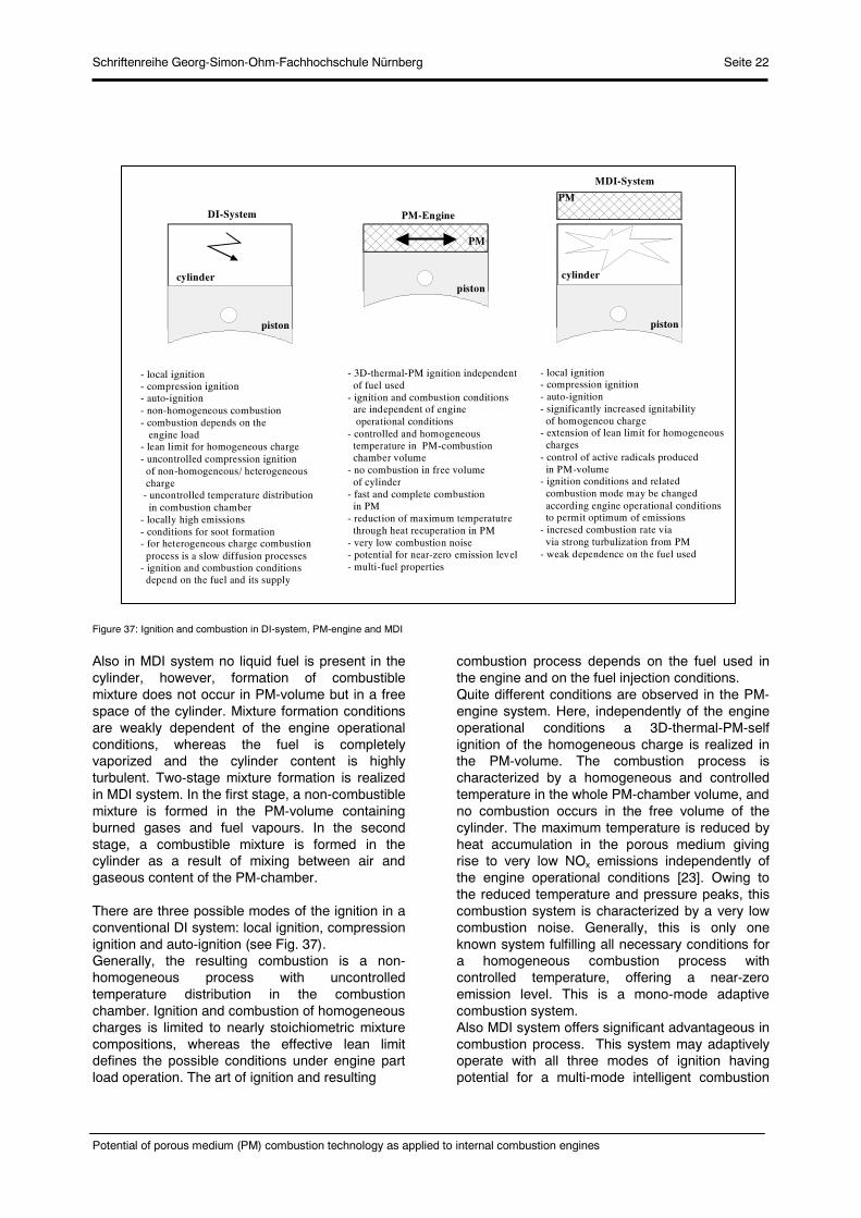
Figure 37: Ignition and combustion in DI-system, PM-engine and MDI
Also in MDI system no liquid fuel is present in the cylinder, however, formation of combustible mixture does not occur in PM-volume but in a free space of the cylinder. Mixture formation conditions are weakly dependent of the engine operational conditions, whereas the fuel is completely vaporized and the cylinder content is highly turbulent. Two-stage mixture formation is realized in MDI system. In the first stage, a non-combustible mixture is formed in the PM-volume containing burned gases and fuel vapours. In the second stage, a combustible mixture is formed in the cylinder as a result of mixing between air and gaseous content of the PM-chamber.
There are three possible modes of the ignition in a conventional DI system: local ignition, compression ignition and auto-ignition (see Fig. 37).Generally, the resulting combustion is a non-homogeneous process with uncontrolled temperature distribution in the combustion chamber. Ignition and combustion of homogeneous charges is limited to nearly stoichiometric mixture compositions, whereas the effective lean limit defines the possible conditions under engine part load operation. The art of ignition and resulting
combustion process depends on the fuel used in the engine and on the fuel injection conditions. Quite different conditions are observed in the PM-engine system. Here, independently of the engine operational conditions a 3D-thermal-PM-self ignition of the homogeneous charge is realized in the PM-volume. The combustion process is characterized by a homogeneous and controlled temperature in the whole PM-chamber volume, and no combustion occurs in the free volume of the cylinder. The maximum temperature is reduced by heat accumulation in the porous medium giving rise to very low NOx emissions independently of the engine operational conditions [23]. Owing to the reduced temperature and pressure peaks, this combustion system is characterized by a very low combustion noise. Generally, this is only one known system fulfilling all necessary conditions for a homogeneous combustion process with controlled temperature, offering a near-zero emission level. This is a mono-mode adaptive combustion system. Also MDI system offers significant advantageous in combustion process. This system may adaptively operate with all three modes of ignition having potential for a multi-mode intelligent combustion
DI-System PM-Engine
MDI-System
- local ignition- compression ignition- auto-ignition- non-homogeneous combustion- combustion depends on the engine load- lean limit for homogeneous charge - uncontrolled compression ignition of non-homogeneous/ heterogeneous charge - uncontrolled temperature distribution in combustion chamber- locally high emissions- conditions for soot formation- for heterogeneous charge combustion process is a slow diffusion processes- ignition and combustion conditions depend on the fuel and its supply
- 3D-thermal-PM ignition independent of fuel used- ignition and combustion conditions are independent of engine operational conditions- controlled and homogeneous temperature in PM-combustion chamber volume- no combustion in free volume of cylinder- fast and complete combustion in PM- reduction of maximum temperatutre through heat recuperation in PM- very low combustion noise- potential for near-zero emission level- multi-fuel properties
PM
PM
piston
piston
piston
cylindercylinder
- local ignition- compression ignition- auto-ignition- significantly increased ignitability of homogeneou charge - extension of lean limit for homogeneous charges- control of active radicals produced in PM-volume- ignition conditions and related combustion mode may be changed according engine operational conditions to permit optimum of emissions- incresed combustion rate via via strong turbulization from PM- weak dependence on the fuel used
Schriftenreihe Georg-Simon-Ohm-Fachhochschule Nürnberg Seite 23
Potential of porous medium (PM) combustion technology as applied to internal combustion engines
system. MDI concept significantly increases ignitability and extends the lean effective limit for homogeneous charges. The combustion conditions are weakly dependent on the fuel used in the engine.
5. Concluding remarks
A porous medium technology has been defined as an utilization of large specific surface area, large heat capacity, high porosity etc. of open cell structures for supporting different processes realized in engine. Especially important is the application of this materials to mixture formation and combustion in engines. In this paper novel concepts for combustion engines based on the application of porous medium technology are presented and discussed. The main attention is focused on the engine concepts having potential for homogeneous combustion process under variable engine operational conditions: intelligent engine and engine with combustion in a porous reactor.
It was shown that porous media, can be used for a great variety of improvements in the combustion process, especially for ellimination of soot emissions and significant reduction of thermal NOx. Combustion process in poorus reactor is homogeneous, flamless and uses a new art of volumetric thermal ignition in the porous medium volume. All these processes (e.g. gas flow, fuel injection and its spatial distribution, vaporization, homogenization, ignition and combustion) can be controlled or positively influenced with the help of porous media/ceramic foams or other structures.
References
[1] Weclas, M., Porous media in internal combustion engines, [in:] Cellular Ceramics-Structure, Manufacturing, Properties and Applications, Scheffler, M., Colombo, P. (eds), Wiley-VCH-Publ.2005. [2] Weclas, M., New strategies for homogeneous combustion in I.C. engines based on the porous medium (PM)-technology, ILASS Europe, June 2001.[3] Weclas, M., Ates, B., and Vlachovic, V., Basic aspects of interaction between a high velocity Diesel jet and a highly porous medium (PM), 9th Int. Conference on Liquid Atomization and Spray Systems ICLASS, 2003.
[4] Durst, F., Weclas, M., A new type of internal combustion engine based on the porous-medium combustion technique, J. Automobile Engineering, IMechE, part D, 2001, Vol. 215, pp. 63-81. [5] Durst, F., Weclas, M., A new concept of IC engine with homogeneous combustion in porous medium (PM), 5th International Symposium on Diagnostics and Modelling of Combustion in Internal Combustion Engines, COMODIA, 2001, Nagoya, Japan. [6] Durst, F., Weclas, M., Method and device for converting heat into work, Patent Application, German Pat. No. 197 53 407, US Pat. No. 6,125,815, 1997. [7] Weclas, M., Verfahren zur Erzeugung eines Flüssigbrennstoff-/Luftgemisches zum Betrieb einer Wärmekraftmaschine, German Pat. Appl. No. 198 13 891, 1998. [8] Weclas, M., Strategy for intelligent Internal Combustion engine with homogeneous combustion in cylinder, Sonderdruck Schriftenreihe University of Applied Sciences in Nuernberg, 2004, No. 26, pp.1-14.[9] Hanamura, K., Nishio, S., A feasibility study of reciprocating-flow super-adiabatic combustion engine, The 6th ASME-JSME Thermal Engineering Joint Conference, 2003, Paper No. TED-AJ03-547. [10] Particulate traps for heavy duty vehicles, Report of Swiss Agency for the Environment, Forests and Landscape (SAEFL), 2000, Environmental Documentation No. 130. [11] Park, C-W., Koviany, M., Evaporation-Combustion affected by in-cylinder, reciprocating porous regenerator, Trans. of ASME, 2002, Vol. 124, pp. 184-194. [12] Mayer, A., Definition, Measurement and Filtration of ultrafine solid Particles emitted by Diesel engines, ATW-EMPA-Symposium 19th of April 2002. [13] Schäfer-Sindlinger, A., Vogt, C.D., Hashimoto, S. Hamanaka, T., Matsubara, R., New Materials for Particulate Filters in Passenger Cars, Auto Technology, 2003, No. 5. [14] Weclas, M., Diesel soot (PM) emissions and DPF technologies: state of the art, Internal Report, 2004, Institute of Vehicle Technology, University of Applied Sciences in Nuernberg [15] Bovonsombat,P., Kang,B-S., Spurk,P., Klein, H., Ostgathe, K., Development of Current and Future Diesel After Treatment Systems, MECA/AECC Meeting, 2001, Bangkok, February 1. [16] Kusaka, J., Yamamato, T., Daisho, Y., Simulating the homogeneous charge compression ignition process using a detailed kinetic model for n-heptane mixtures, Int. J. Engine Research, 2000, Vol.1, 3, pp. 281-289.

Schriftenreihe Georg-Simon-Ohm-Fachhochschule Nürnberg Seite 24
Potential of porous medium (PM) combustion technology as applied to internal combustion engines
[17] Urushihara, T., Hiraya, K., Kakuhou, A., Itoh, T., Parametric study of gasoline HCCI with various compression ratios, intake pressures and temperatures, Proc. A New Generation of Engine Combustion Processes for the Future?, Ed. P. Duret, 2001, pp.77-84. [18] Haßler, S., Homogene Verbrennung in Motoren als Lösung zur Emissions- und Verbrauchsreduzierung: Ansätze und Perspektiven, Diplomarbeit at University of Applied Sciences in Nuernberg, Suppervisor: M. Weclas, August 2004. [19] Coma, G., Gastaldi, P., Hardy, J.P., Maroteaux, D., HCCI combustion: dream or reality? Proc. of 13th Aachen Colloquium on Vehicle and Engine Technology, 2004, Aachen, pp. 513-524. [20] Weclas, M., Melling, A., Durst, F., Unsteady intake valve gap flows, SAE Technical Paper, No. 952477, 1995. [21] Weclas, M., Melling, A., Durst, F., Flow separation in the inlet valve gap of piston engines, Progress in Energy and Combustion Science, 1998, vol. 24 (3), pp.165-195. [22] Brenn, G., Durst, F., Trimis, D., Weclas, M., Methos and tools for advanced fuel spray production and investigation, Atomization and Sprays, 1997, vol. 7, pp. 43-75.
[23] Durst, F., Weclas, M., Mößbauer, S., A New Concept of Porous Medium Combustion in I.C. Engines, International Symposium on Recent Trends in Heat and Mass Transfer, 2002, Guwahati, India.
.