potential applications of model checking in pra - v2
TRANSCRIPT
This document is downloaded from theVTT’s Research Information Portalhttps://cris.vtt.fi
VTThttp://www.vtt.fiP.O. box 1000FI-02044 VTTFinland
By using VTT’s Research Information Portal you are bound by thefollowing Terms & Conditions.
I have read and I understand the following statement:
This document is protected by copyright and other intellectualproperty rights, and duplication or sale of all or part of any of thisdocument is not permitted, except duplication for research use oreducational purposes in electronic or print form. You must obtainpermission for any other use. Electronic or print copies may not beoffered for sale.
VTT Technical Research Centre of Finland
Potential applications of model checking in probabilistic risk assessmentsHelminen, Atte; Pakonen, Antti
Published: 06/02/2020
Document VersionPublisher's final version
Link to publication
Please cite the original version:Helminen, A., & Pakonen, A. (2020). Potential applications of model checking in probabilistic risk assessments.VTT Technical Research Centre of Finland. VTT Research Report No. VTT-R-00017-20
Download date: 23. Jan. 2022

RESEARCH REPORT VTT-R-00017-20
Potential applications of model checking in probabilistic risk assessments Authors: Atte Helminen, Antti Pakonen
Confidentiality: Public

RESEARCH REPORT VTT-R-00017-20
1 (18)
Report’s title
Potential applications of model checking in probabilistic risk assessments Customer, contact person, address Order reference
Ministry of Economic Affairs and Employment of Finland / Nuclear Waste Management Fund, Jorma Aurela
SAFIR 6/2019
Project name Project number/Short name
Safety and security assessment of overall I&C architectures 122061/SEARCH Author(s) Pages
Atte Helminen, Antti Pakonen 13/13 Keywords Report identification code
Digital I&C systems, model checking, probabilistic risk assessment, software reliability estimation
VTT-R-00017-20
Summary
In model checking, a model of instrumentation and control (I&C) system’s application logic is created to formally verify the correct functioning of a system model by examining all of its possible behaviours. Model checking can provide important information on the failures of digital I&C systems and their software in particular. The integration of model checking with probabilistic risk assessment (PRA) modelling has been studied previously in two separate case studies. In the report, an overview to the common taxonomy of failure modes and current practices of modelling digital I&C systems in PRA is given. Findings from the previous case studies are reflected to the PRA modelling practices. Design issues identified by model checking in various VTT customer projects are compared to the failure modes and failure effects of software modules collected from different taxonomies for PRA. The case studies propose a coupling approach where the results of PRA are used to support model checking. The model checking analysis is restricted to a limited set of postulated hardware failures based on PRA results, potentially improving scalability of model checking. In this report, the focus is reversed and the focus is on studying how model checking can support PRA and its taxonomy. In order to use the model checking method as a support analysis for PRA modelling the complementary uses of the modelling methods should be developed. Potential complementary uses are for example: 1) The identification and analysis of extraordinary failure modes, including software failure modes, and potential detection of these failure modes; 2) Software reliability assessment of important functions; 3) The analysis and modelling of dynamic, i.e. time-dependent, features.
Confidentiality Public
Espoo, 6.2.2020 Written by Atte Helminen Senior Scientist
Reviewed by Kim Björkman Research Scientist
Accepted by Emmanuel Ory Research Team Leader
VTT’s contact address
P.O. Box 1000, FI-02044 VTT, Finland
Distribution (customer and VTT)
SAFIR2022 programme
The use of the name of VTT Technical Research Centre of Finland Ltd in advertising or publishing of a part of this report is only permissible with written authorisation from VTT Technical Research Centre of Finland Ltd.

RESEARCH REPORT VTT-R-00017-20
2 (18)
Contents
Contents ................................................................................................................................... 2
1. Introduction ......................................................................................................................... 3
2. Current practice of modelling digital I&C in PRA ................................................................ 3
2.1 Common taxonomy of failure modes for digital I&C systems ..................................... 3 2.2 Failure modes on different levels of abstraction ......................................................... 4 2.3 Failure modes and effects analysis (FMEA) ............................................................... 5 2.4 Comparative study on digital I&C modelling approaches for PRA ............................. 7
3. Model checking method and previous coupling with PRA .................................................. 7
3.1 Model checking method ............................................................................................. 7 3.2 Coupling of model checking with PRA ........................................................................ 7 3.3 Results of the previous case studies .......................................................................... 8
4. Comparison of model checking design issues with the failure mode taxonomy for PRA ... 9
5. Discussion ........................................................................................................................ 13
5.1 Conclusions of the previous case studies ................................................................ 13 5.2 Comparison of design issues with failure mode taxonomy ....................................... 13 5.3 Complementary uses of modelling approaches ....................................................... 14
5.3.1 Extraordinary and software failure modes .................................................... 14
5.3.2 Software reliability assessment .................................................................... 15
5.3.3 Modelling dynamic features .......................................................................... 15
6. Conclusions ...................................................................................................................... 16
References ............................................................................................................................. 17

RESEARCH REPORT VTT-R-00017-20
3 (18)
1. Introduction
Model checking can provide important information on the failures of digital instrumentation and control (I&C) systems and its software in particular. Due to the nature of software, it doesn’t wear or tear in time similar to hardware. Software failures are design failures, which are triggered by the combination of internal memory state of system and the system’s inputs. Software failures are typically rare and hard to predict and identify. They are mainly caused by systematic (i.e. design specification or modification) faults, and not by random errors. The systematic nature of software failures, i.e. the same failure can be triggered in similar systems simultaneously, makes their study particularly important in the context of probabilistic risk assessments (PRA) and nuclear safety.
In model checking, a model of I&C system’s application logic is created to formally verify the correct functioning of a system model by examining all of its possible behaviours. The approach can be valuable in discovering complex scenarios. Therefore, model checking can provide important support for the definition of failure modes in the software failure modelling of PRA.
The integration of model checking with PRA modelling has been studied previously in two separate case studies presented in [1] and [2]. In this report, an overview to the common taxonomy of failure modes and current practices of modelling digital I&C systems in PRA is given. The results of the case studies are analysed and the findings are reflected to the current modelling practices. Based on the findings a discussion is given on how the model checking could benefit the PRA and its taxonomy, and how the integration of the two modelling methods should be focused in the future research.
The report is composed as follows. Section 2 gives an introduction to the common taxonomy of failure modes of digital I&C systems and the current practices of modelling digital I&C systems in PRA. Section 3 describes the model checking method and its previous coupling with PRA. Section 4 compares the design issues identified in previous VTT customer projects to the taxonomy of software failure modes and effects. Section 5 discusses the previous coupling results and highlights topics for the potential complementary uses of the methods in the future. Section 6 is left for conclusions.
2. Current practice of modelling digital I&C in PRA
2.1 Common taxonomy of failure modes for digital I&C systems In [3], a common taxonomy of failure modes for digital I&C systems is presented. The taxonomy has been developed in DIGREL project by Working Group on Risk Assessment (WGRISK) of OECD Nuclear Energy Agency, and it is seen as an important step towards standardised digital I&C modelling and reliability analysis techniques for PRA.
Needs from PRA have guided the development work, meaning e.g. that the digital system and its failures are studied from their functional significance point of view. The taxonomy is deliberately focused on the reliability analysis of the reactor protection system, which reduces the scope of failure modes and failure effects considerably.
The summary presented in [4] is used to give a short introduction to the taxonomy, and in particular, to the failure mode part of the taxonomy. The taxonomy is based on a hierarchical definition of five levels of abstraction: 1) system level, 2) division level, 3) I&C unit level, 4) I&C unit modules level, 5) basic components level. The different levels and examples of their entities in nuclear safety I&C are demonstrated in Figure 1.

RESEARCH REPORT VTT-R-00017-20
4 (18)
Figure 1. Different levels of abstraction for nuclear safety I&C.
The taxonomy is developed using a specific conceptual model of failure and failure propagation. The failure model and the taxonomy consist of the following elements: fault location, failure mode, uncovering situation, failure effect and the end effect.
These elements are used to define the relationship between a fault in hardware or software modules (module level failure modes) and the end effect on I&C units (I&C unit level failure modes). In the analysis, a fault is postulated in a hardware or software module (fault location). For hardware modules, different failure modes are explicitly defined. Software module failure modes are directly associated with the failure effect. Uncovering situation describes when, where and how the module failure is significant at the I&C unit level. A taxonomy of generic failure effects is defined to provide a simple but exhaustive way to categorise the effect of wrong output in a module.
The end effect describes the final propagation of the failure, taking into consideration all these elements of the failure model. In this consideration, a distinction can be made between the “maximum possible end effect”, when fault tolerance design (FTD) is not effective or does not exist, and the “most likely end effect”, assumes that FTD features are present and effective. FTD is effective only when the fault is detected by online monitoring, which is one of the uncovering situation categories.
2.2 Failure modes on different levels of abstraction The safety-related function of the system is defined as the generation of safety-related actuation signal in a predefined time interval only when required. An output of the system is a set of outputs of the divisions. Thus, the failure modes in the division level are similar with those of the system level, and therefore the failure modes on the system and division level can be defined as:
Failure to actuate the function (including late actuation); Spurious actuation.
For the functional impacts of I&C units a difference is distinguished between the impact on a single I&C unit and impact on multiple I&C units. The latter is especially important when
I/O c
ard
Mot
her
boa
rd
Com
mun
icat
ion
mo
dule
Op
tica
l cab
le
Oth
er m
odu
les
I/O c
ard
Mot
her
boa
rd
Com
mun
icat
ion
mo
dule
Op
tica
l cab
le
Oth
er m
odu
les
I/O c
ard
Mot
her
boa
rd
Com
mun
icat
ion
mo
dule
Op
tica
l cab
le
Oth
er m
odu
les
I/O c
ard
Mot
her
boa
rd
Com
mun
icat
ion
mo
dule
Op
tica
l cab
le
Oth
er m
odu
les
A/D
co
nv
MU
X
Sig
nal a
mpl
Mic
ropr
oce
ssor
Oth
er
com
pon
ents
D/A
co
nv
DE
MU
X
Tra
nsm
itter
Sof
twar
e

RESEARCH REPORT VTT-R-00017-20
5 (18)
analysing the impacts of software faults (systematic fault in the design). From a single I&C unit point of view, the following functional failure modes on the I&C unit level can be considered:
Loss of all functions (outputs) of the I&C unit; Loss of a specific function; Spurious output (all functions); Spurious output (one function).
The above list is not exhaustive, and e.g. for voting units the functional end effect may be more complex (e.g. degraded voting logic).
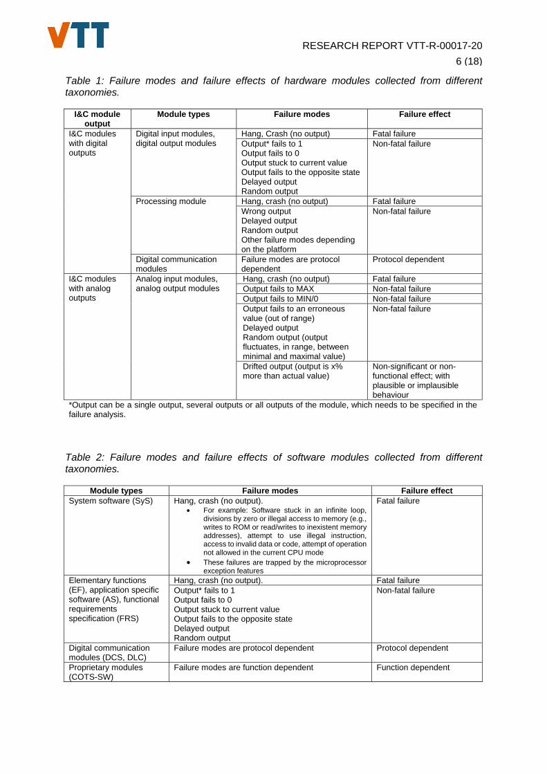
At the module level, a distinction is made between the treatment of hardware and software related failure modes. Typical examples of failure modes for hardware and software modules are shown in Table 1 and Table 2, which have been collected from the taxonomy working group members (see appendix of [3]).
At the basic component level, with regarding to the hardware of basic components, the assessment of failure modes and effects is similar to the module level assessment. In most cases, module level assessment is sufficient. Basic component level may be needed if failure data is available at that level and if basic components form CCF groups which are not covered by module level CCF groups.
With regarding to the software of basic components, the module level as defined above is the most detailed level of abstraction considered. The next level would be the line of codes, which are both far too detailed elements for any reliability analysis and also practically non-accessible for the analysts.
2.3 Failure modes and effects analysis (FMEA) An important part of a system analysis in developing a reliability model is performance of an FMEA. The results of the FMEA can provide a basis of the associated reliability model, such as a (system) fault tree model to be part of the plant-specific PRA. The FMEA would provide the relationships between the system level failure modes and more detailed level failure modes, fault tolerance design features, and dependencies (including possibly plant processes and operator actions).
FMEA for reactor protection system can be developed e.g. in the following levels:
the actuators (pumps, valves, diesel generators, etc.); I&C units and communication links; I&C functions; hardware and software modules of I&C units.
FMEA for the actuators is carried out in standard manner as part of the process system FMEAs. In this analysis the critical actuation signals and associated DC power supply dependencies need to be identified. The analysis shall provide link to the I&C units and I&C functions controlling the actuator.
In the FMEA for I&C units (e.g. VUs and APUs), power supply, the I&C functions, modules and communication links are identified. Analysis of I&C functions shall identify associated I&C units and software modules for each function. Fail-safe principles can be identified in this context.
RESEARCH REPORT VTT-R-00017-20
6 (18)
Table 1: Failure modes and failure effects of hardware modules collected from different taxonomies.
I&C module output
Module types Failure modes Failure effect
I&C modules with digital outputs
Digital input modules, digital output modules
Hang, Crash (no output) Fatal failure Output* fails to 1 Output fails to 0 Output stuck to current value Output fails to the opposite state Delayed output Random output
Non-fatal failure
Processing module Hang, crash (no output) Fatal failure Wrong output Delayed output Random output Other failure modes depending on the platform
Non-fatal failure
Digital communication modules
Failure modes are protocol dependent
Protocol dependent
I&C modules with analog outputs
Analog input modules, analog output modules
Hang, crash (no output) Fatal failure Output fails to MAX Non-fatal failure Output fails to MIN/0 Non-fatal failure Output fails to an erroneous value (out of range) Delayed output Random output (output fluctuates, in range, between minimal and maximal value)
Non-fatal failure
Drifted output (output is x% more than actual value)
Non-significant or non-functional effect; with plausible or implausible behaviour
*Output can be a single output, several outputs or all outputs of the module, which needs to be specified in the failure analysis.
Table 2: Failure modes and failure effects of software modules collected from different taxonomies.
Module types Failure modes Failure effect System software (SyS) Hang, crash (no output).
For example: Software stuck in an infinite loop, divisions by zero or illegal access to memory (e.g., writes to ROM or read/writes to inexistent memory addresses), attempt to use illegal instruction, access to invalid data or code, attempt of operation not allowed in the current CPU mode
These failures are trapped by the microprocessor exception features
Fatal failure
Elementary functions (EF), application specific software (AS), functional requirements specification (FRS)
Hang, crash (no output). Fatal failure Output* fails to 1 Output fails to 0 Output stuck to current value Output fails to the opposite state Delayed output Random output
Non-fatal failure
Digital communication modules (DCS, DLC)
Failure modes are protocol dependent Protocol dependent
Proprietary modules (COTS-SW)
Failure modes are function dependent Function dependent

RESEARCH REPORT VTT-R-00017-20
7 (18)
FMEA for hardware and software modules can be performed in a generic manner. Failure modes and effects are module type specific but otherwise generic. With regard to the input and output modules, allocation of I&C functions between the modules and even the channels of the modules should be identified. This is needed for the determination of the test interval of the input and output modules.
2.4 Comparative study on digital I&C modelling approaches for PRA A comparative study on the digital I&C modelling approaches for PRA has been initiated in DIGMAP project by WGRISK. The project started in 2017 and is expected to conclude in 2020. Participating countries include Republic of Korea, Switzerland, Finland, Germany, France, The Netherlands, United Kingdom and Czech Republic.
The objective of DIGMAP project [5] is to compare modelling approaches used in the participating countries for safety-important digital I&C systems in an example NPP. The example NPP description is developed based on the descriptions of DIGREL project [3]. The model is a fictive boiling water reactor (BWR) with simplified systems except for the more detailed digital I&C description. Each participant is expected to develop an own digital I&C PRA model based on the provided system layout of the example NPP. The PRA models are benchmarked for the loss of main feed-water accident. The different models will be shared, discussed and compared. Through the comparisons valuable insights for the future modelling method development can be identified. These insights concern e.g. methods, the level of detail applied and quantification issues.
3. Model checking method and previous coupling with PRA
3.1 Model checking method Model checking [6] is a computer aided formal verification method for the verification of hardware or software systems. In model checking, a desired property is verified over a system model. The main benefit of model checking is that model checking tools are able to perform an exhaustive verification with respect to desired property. Given the model and the formalised requirements as input, a model-checker automatically determines whether the system has violated its requirements. If a system model fails to satisfy a desired property, the model checker will give a counter-example that demonstrates a behaviour that violates the property. Practical application of I&C system model checking in the Finnish nuclear industry is discussed in [7].
Model checking has been proven an effective method, when focusing on the I&C software, alone. The exhaustive analysis reveals unlikely and complex scenarios, involving unlikely operator behaviour, unusual feedback from the process, and/or very exact timing of unrelated events [7]. However, in order to analyse failure tolerance, different failure modes of the underlying I&C hardware would need to be included in the model. Different approaches for modelling hardware failures have been suggested (e.g., [8],[9]), but there remain questions about the scalability of such approaches for very large and complex models.
3.2 Coupling of model checking with PRA The coupling of model checking methodology with PRA has been studied in case studies presented in [1] and [2]. In [1], a concept-level coupling approach is developed. The coupling approach is illustrated in Figure 2. The main idea of the approach is that the model checking analysis is restricted to a smaller set of postulated component failures, based on PRA results. This aims to improve the scalability of model checking. Performing exhaustive model checking for a digital instrumentation and control (I&C) system, when both hardware failures and the

RESEARCH REPORT VTT-R-00017-20
8 (18)
detailed functionality of the I&C system are considered, can be challenging due to scalability issues.
Figure 2. An approach for integration of model checking and PRA.
PRA is first used to calculate minimal cut sets (MCS) of the system. Based on the minimal cut sets, verification is performed using model checking. The verification is performed from several points of view. If all failures belonging to a MCS are assumed, it is expected that the checked property (e.g. success criterion) is not fulfilled. For example, for the case study system of [1] the model-checking success criterion is interpreted as follows: “If the water level is below the low limit, the valve is closed.” If the model checker does not confirm this, it is likely because of an error in the PRA model (or the model-checking model).
If only a subset the components in an MCS is assumed failed, the success criterion should be fulfilled. If this is not the case, the model checker will produce a counter-example scenario. The counter-example will show how the combination of application software behaviour, together with the assumed component failures, can cause the success criterion to fail. If such a scenario is found using model checking, the risk importance of the scenario should be analysed. Also the PRA model should be changed to accommodate for the scenario. Alternatively, if the scenario is severe, it should lead to a system design revision.
According to [1], the proposed approach can be used for: 1) identifying spurious failures manifested during hardware failures; 2) verifying the fault-tolerance of a system; 3) identifying new scenarios in which a safety function of the plant is not adequately performed; and 4) finding errors in the PRA model.
To demonstrate the usability of the developed coupling approach, the first case study was performed in [1] for a simple feedwater tank system. The approach was tested for a larger system in the second case study in [2]. The larger system represents a model of fictive, simplified boiling water reactor (BWR). The larger model incorporates the possibility to divide the system into sub-systems that can be analysed individually.
3.3 Results of the previous case studies The results of the first case study indicated that the model checking enabled the discovery of a set of previously unknown failure scenarios in the example I&C system. The scenarios occurred due to different hardware errors in combination with a software design error that was

RESEARCH REPORT VTT-R-00017-20
9 (18)
not accounted for in the PRA model. From the scalability point of view the small-scale case study on the approach seemed quite promising.
It should be, however, noted that the results of a PRA model are always the product of identified failure modes of the modelled system and its components. Therefore, a PRA model cannot create MCS for failures, which aren’t originally in the scope of the model.
In the second case study [2], the applicability of the coupling approach was studied by performing a case study using a more complex example system, based on a fictitious reference model of a boiling water nuclear reactor [4]. The focus of the case study was on assessing the scalability of model checking when the analysis is restricted based on PRA results. The results of the case study demonstrated that the analysis time decreases considerably when the failure behaviour is restricted. PRA results were used to specify critical failure points in the system architecture and the failure modules were added into those positions. The limitations include the restricted scope and the manual labour needed to build the models. The focus is to perform model checking of the I&C system using a restricted set of hardware failure combinations selected based on PRA results, e.g. based on top 50 minimal cut sets. It is noted that it is not guaranteed that such a model checking analysis scope is sufficient. It is possible that individual failures that do not occur in the most important minimal cut sets can also, together with a software design error, cause potentially unsafe scenarios. However, analysing a larger set minimal cut sets may not be any longer practical.
4. Comparison of model checking design issues with the failure mode taxonomy for PRA
Since 2008, VTT has applied model checking in various customer projects in the Finnish nuclear industry [7]. By 2019, 57 I&C system design issues have been identified, in some cases leading to design changes. A design issue, here, means that the analysis revealed a practical, verifiable example of a scenario, where a certain chain of events leads to the I&C system ending up in a state that is contrary to a given functional requirement. The practical likelihood and/or safety relevance of the issues varies.
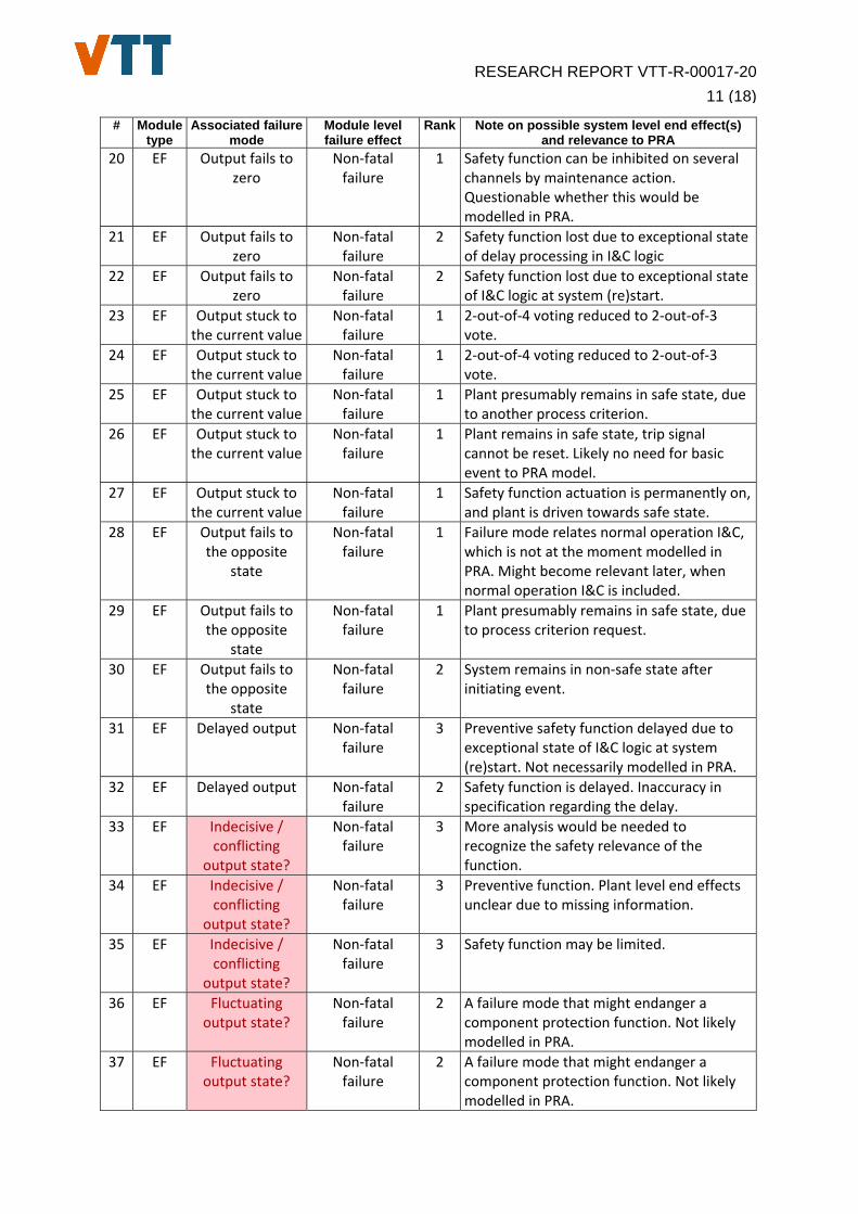
In Table 3, the design issues identified by model checking are compared to the failure modes and failure effects of software modules collected from different taxonomies for PRA. The failure modes and failure effects of software modules were listed in Table 2.
From the PRA modelling point of view the main interest is in the end effects of software failures. The end effects are dependent on the involved system, overall system architecture and effectiveness of fault tolerance design. The evaluation of end effects can be laborious and requires detailed information on the plant design. Some of the analysed models in model checking were not based on detailed design, but early functional design diagrams or other conceptual documents. For some of the issues in Table 3, detailed analysis of the plant level end effects was impossible due to necessary information not being available to the authors.
In the comparison, notes on the possible end effects and their relevance to PRA modelling are given. These notes should be seen as examples and considered with a caveat. They are subjective insights to the end effects with incomplete information on the overall system architecture and plant design.
A rank value is given for each design issue. The rank value estimates the difficulty to analyse and classify the design issue with the given taxonomy and to evaluate its possible end effects and relevance to PRA modelling. The availability of information influences the rank value. The ranking ranges from 1 (easy) to 3 (hard).

RESEARCH REPORT VTT-R-00017-20
10 (18)
Table 3: Comparison of design issues found in model checking to failure modes and effects of software modules and notes on their possible system level end effects.
# Module type
Associated failure mode
Module level failure effect
Rank Note on possible system level end effect(s) and relevance to PRA
1 EF Output fails to one
Non‐fatal failure
1 2‐out‐of‐4 voting reduced to 2‐out‐of‐3 vote.
2 EF Output fails to one
Non‐fatal failure
1 Control function related. Plant driven towards safe state. Not modelled in PRA.
3 EF Output fails to one
Non‐fatal failure
2 Four independent failures, the following module will compensate.
4 EF Output fails to one
Non‐fatal failure
2 Plant is in safe state. More analysis would be needed to recognize the failure mode(s) and potential end effect(s) for PRA.
5 EF Output fails to one
Non‐fatal failure
1 Plant is in safe state. Test signal stored in delay element leads to spurious actuation.
6 EF Output fails to one
Non‐fatal failure
1 Plant is in safe state. Test signal stored in memory leads to spurious actuation.
7 EF Output fails to one
Non‐fatal failure
3 Plant level end effects unclear due to missing information.
8 EF Output fails to one
Non‐fatal failure
2 Related to preventive safety function, not likely modelled in PRA.
9 EF Output fails to one
Non‐fatal failure
2 Short equipment transient due to test, plant remains in safe state.
10 EF Output fails to one
Non‐fatal failure
1 Specific function to prevent temporary failure mode in diesel startup test. Not modelled in PRA.
11 EF Output fails to one
Non‐fatal failure
1 Specific function to prevent temporary failure mode in diesel startup. Not necessarily modelled in PRA.
12 EF Output fails to one
Non‐fatal failure
3 Spurious actuation of safety function may lead to leak of radionuclides. More analysis would be needed to recognize the failure mode(s) and potential end effect(s) for PRA.
13 EF Output fails to one
Non‐fatal failure
3 Spurious actuation of safety function reduces options for controlling accident.
14 EF Output fails to one
Non‐fatal failure
2 Spurious actuation of safety function. Most likely no safety significance.
15 EF Output fails to one
Non‐fatal failure
3 Two independent failures, the following module will compensate.
16 EF Output fails to zero
Non‐fatal failure
2 2‐out‐of‐4 voting reduced to 2‐out‐of‐3 vote.
17 EF Output fails to zero
Non‐fatal failure
2 Component protection failure may lead to loss of safety function later.
18 EF Output fails to zero
Non‐fatal failure
1 Failure mode relates normal operation I&C, which is not at the moment modelled in PRA. Might become relevant later, when normal operation I&C is included.
19 EF Output fails to zero
Non‐fatal failure
1 Indicative function fails. Not modelled in PRA.
RESEARCH REPORT VTT-R-00017-20
11 (18)
# Module type
Associated failure mode
Module level failure effect
Rank Note on possible system level end effect(s) and relevance to PRA
20 EF Output fails to zero
Non‐fatal failure
1 Safety function can be inhibited on several channels by maintenance action. Questionable whether this would be modelled in PRA.
21 EF Output fails to zero
Non‐fatal failure
2 Safety function lost due to exceptional state of delay processing in I&C logic
22 EF Output fails to zero
Non‐fatal failure
2 Safety function lost due to exceptional state of I&C logic at system (re)start.
23 EF Output stuck to the current value
Non‐fatal failure
1 2‐out‐of‐4 voting reduced to 2‐out‐of‐3 vote.
24 EF Output stuck to the current value
Non‐fatal failure
1 2‐out‐of‐4 voting reduced to 2‐out‐of‐3 vote.
25 EF Output stuck to the current value
Non‐fatal failure
1 Plant presumably remains in safe state, due to another process criterion.
26 EF Output stuck to the current value
Non‐fatal failure
1 Plant remains in safe state, trip signal cannot be reset. Likely no need for basic event to PRA model.
27 EF Output stuck to the current value
Non‐fatal failure
1 Safety function actuation is permanently on, and plant is driven towards safe state.
28 EF Output fails to the opposite
state
Non‐fatal failure
1 Failure mode relates normal operation I&C, which is not at the moment modelled in PRA. Might become relevant later, when normal operation I&C is included.
29 EF Output fails to the opposite
state
Non‐fatal failure
1 Plant presumably remains in safe state, due to process criterion request.
30 EF Output fails to the opposite
state
Non‐fatal failure
2 System remains in non‐safe state after initiating event.
31 EF Delayed output Non‐fatal failure
3 Preventive safety function delayed due to exceptional state of I&C logic at system (re)start. Not necessarily modelled in PRA.
32 EF Delayed output Non‐fatal failure
2 Safety function is delayed. Inaccuracy in specification regarding the delay.
33 EF Indecisive / conflicting
output state?
Non‐fatal failure
3 More analysis would be needed to recognize the safety relevance of the function.
34 EF Indecisive / conflicting
output state?
Non‐fatal failure
3 Preventive function. Plant level end effects unclear due to missing information.
35 EF Indecisive / conflicting
output state?
Non‐fatal failure
3 Safety function may be limited.
36 EF Fluctuating output state?
Non‐fatal failure
2 A failure mode that might endanger a component protection function. Not likely modelled in PRA.
37 EF Fluctuating output state?
Non‐fatal failure
2 A failure mode that might endanger a component protection function. Not likely modelled in PRA.

RESEARCH REPORT VTT-R-00017-20
12 (18)
# Module type
Associated failure mode
Module level failure effect
Rank Note on possible system level end effect(s) and relevance to PRA
38 EF Incorrect control parameter?
Non‐fatal failure
3 Incorrect setpoint due to incorrect internal system state. More analysis would be needed to recognize the failure mode(s) and potential end effects(s) for PRA.
39 EF Incorrect control parameter?
Non‐fatal failure
3 Incorrect setpoint due to incorrect state specification for the system. More analysis would be needed to recognize the failure mode(s) and potential end effect(s) for PRA.
40 EF Incorrect control parameter?
Non‐fatal failure
3 Safety function may be limited.
41 EF Incorrect control parameter?
Non‐fatal failure
3 Safety function may be limited.
42 N/A N/A N/A 2 Control function related. Not modelled in PRA.
43 N/A N/A N/A 1 Inaccuracy in specification.
44 N/A N/A N/A 1 Inaccuracy in specification.
45 N/A N/A N/A 2 Inaccuracy in specification.
46 N/A N/A N/A 1 Incompleteness of specification.
47 N/A N/A N/A 1 Incompleteness of specification.
48 N/A N/A N/A 1 Incorrect internal system state.
49 N/A N/A N/A 1 Incorrect internal system state.
50 N/A N/A N/A 1 Periodic test fails, no effect on plant operation.
51 N/A N/A N/A 2 Plant remains in safe state, exceptional state of I&C logic due to maintenance action.
52 N/A N/A N/A 2 Plant remains in safe state, exceptional state of I&C logic during I&C system startup.
53 N/A N/A N/A 3 Redundant systems can be put to test mode simultaneously. More analysis would be needed to recognize the failure mode(s) and potential end effect(s) for PRA.
54 N/A N/A N/A 3 Redundant systems can be put to test mode simultaneously. More analysis would be needed to recognize the failure mode(s) and potential end effect(s) for PRA.
55 N/A N/A N/A 1 Testing logic of preventive functions fails. Not modelled in PRA.
56 N/A N/A N/A 3 Unspecified output due to incorrect internal system state. More analysis would be needed to recognize the failure mode(s) and potential end effect(s) for PRA.
57 N/A N/A N/A 3 Unspecified output due to incorrect internal system state. More analysis would be needed to recognize the failure mode(s) and potential end effect(s) for PRA.

RESEARCH REPORT VTT-R-00017-20
13 (18)
5. Discussion
5.1 Conclusions of the previous case studies Based on the review of the previous case studies, the original idea of coupling model checking methodology with PRA focuses mainly on the needs of model checking. In the coupling approach, the needs of PRA are not considered. The results from PRA are used for restricting the model checking analysis and feedback from model checking to PRA is limited only on the identification of potential unknown failure scenarios, which should perhaps be included in the PRA model.
The need to apply the PRA results in the coupling approach in the first place is somewhat unclear. If the purpose is to restrict the state space of model checking calculations, the same outcome can, basically, be achieved by just using information from the system architecture and some heuristic rules.
From PRA needs perspective, the general idea of the coupling approach presented in 3.2 should be revised. Model checking is basically a system’s verification method, while PRA is the risk model of a system. Therefore, using PRA model to support model checking can be challenging. The reason is twofold. The first reason, and likely the less dominant reason, is the different levels of abstraction in the two modelling approaches. The second reason, and likely the more dominant reason, is that the two modelling approaches are used for different objectives.
Regarding the level of abstraction, as mentioned in Section 2.2, the most detailed level of abstraction considered in the PRA modelling is the module level. For many cases, even the module level can be too detailed from the overall PRA modelling perspective and I&C unit level is sufficient. In the model checking, the modelling can be performed in any abstraction level, all the way to the basic component level if necessary.
Regarding the different objectives, as stated above a PRA model is essentially a model of a system’s failure combinations, their probabilities and their possible consequences to the functioning of the system and its interfacing systems. Model-checking model, on the other hand, is a finite state model of a system trying to identify potential failure modes for the system. One could state in a big picture that the PRA modelling begins from the results of model checking, and other similar analysis and modelling approaches. There is an inherent difference in the objectives of PRA and model checking models.
It seems only rational to reverse the coupling approach of the two modelling methods, so that model checking is used more as the support analysis of PRA, and not opposite, as implied in the original coupling approach.
5.2 Comparison of design issues with failure mode taxonomy The findings of model checking in various customer projects are compared to the common taxonomy of failure modes. The results of the comparison are shown in Table 3. For most findings, it was possible to associate the design issue with a software failure mode listed in Table 2. For the findings at the end of list, it was either difficult to relate the design issues with a specific failure mode or it was evident that the possible failure mode would have no relevance to PRA. Some of the design issues were connected to an indecisive, conflicting or fluctuating output state, or to an incorrect control parameter. For these design issues, new failure mode classes were proposed and they are marked with red colour in Table 3. As mentioned earlier, the original taxonomy is focused on the reliability analysis of the reactor protection system reducing the scope of failure modes.
As mentioned in Section 2.1, software module failure modes are directly associated with the software module level failure effects. In Table 2, software module failure modes which don’t

RESEARCH REPORT VTT-R-00017-20
14 (18)
produce output (i.e. “hang, crash”) are labelled as fatal failures, and the other failure modes as non-fatal. In [3], the following description is given on the distinction of fatal and non-fatal failure effects: “The failure effects defined at I&C units level are the same than those defined at I&C modules and basic components level. A fatal failure of an I&C unit by definition affects all functions of the unit, and the end effect depends on the fault tolerant design. Non-fatal failure affects specific I&C function(s) while the others remain unaffected.” Without more detailed information on the system architecture and its functional allocation, the software module level failure effect was reduced to the produced output of a software module.
The overall question on the comparison is how to benefit from the design issues revealed in model checking analysis in PRA. As discussed above, model checking aims to verify the correctness of design. If some inconsistency is found in model checking, the problem is analysed in detail and corrected if necessary. PRA model on the other hand tries to incorporate the potential failure modes still existing in the system. After finding and fixing a design fault of a system based on the model checking results, the design fault may not be relevant for PRA any longer. However, information on the existence, or non-existence, of design faults and the fixing of these faults increases our confidence on the system reliability. This confidence building is especially important for software. As mentioned in the introduction software failures are typically rare and hard to predict, therefore, model checking can provide valuable support in the reliability estimation of software.
5.3 Complementary uses of modelling approaches The two modelling approaches share a common interest in solving the same goal, i.e. how to make sure a system will function safe enough in safety-critical applications, especially if the system embodies digital I&C. The modelling approaches also have clear connection points. Therefore, the question is what better complementary uses could be found for the methods.
Due to the level of abstraction and the different objectives of the modelling approaches, it would be only rational to apply model checking as a support analysis for the PRA modelling. There are several assets model checking can provide. In [10], a feasibility study on the integration of PRA methods and model checking is presented. The study identifies 12 different approaches, or more like topics, where model checking and PRA could be coupled together. Potential applications are discussed below for most promising topics from the PRA perspective.
5.3.1 Extraordinary and software failure modes
One topic is the extraordinary failure modes. Model checking is an efficient method to check, for instance, how a faulty input signal (e.g. faulty measurement or mistimed operator action) can propagate through the software logic and if it can cause for example a spurious output signal (spurious actuation) [7]. If a spurious actuation signal is possible, FMEA can be used to assess how it will impact the related safety system. The performing of FMEA for a reactor protection system is described in Section 2.3.
Spurious actuations are one source of possible failure modes, which can be traced with model checking and analysed if they should be included in the PRA model. Integration of model checking with FMEA could provide valuable information in the analysis of difficult and extraordinary failure modes.
For the analysis of software failure modes, the model checking can be a valuable tool in with itself. The functions implemented in software are usually distributed between the microprocessors of the system. Model checking can provide a method to assess the end effects of the software failure modes [9]. So far in the case studies, only hardware failures have been considered, but software failure modes and their end effects could be analysed as well. This would be important for the PRA modelling purposes as explained in Section 2. The failure

RESEARCH REPORT VTT-R-00017-20
15 (18)
effects listed in Table 1 and Table 2 could be verified and compared with the end effects of the system taking the fault tolerance design into consideration. This would help improve the accuracy of PRA model.
5.3.2 Software reliability assessment
One topic is the software reliability assessment. PRA modelling is dependent on the frequency and reliability estimates of the initiating events and basic events implemented to the model. Without realistic estimates it is questionable if certain basic events can be included in the model. Having plausible reliability estimates is particularly important for digital I&C systems for which there is only limited amount of operational data available on their functioning in the safety-critical application under examination.
As introduced in Section 3.1, model checking is a computer aided automatic verification technique for formally verifying the correct functioning of a system design model against its formal specification. A model checking model is not the same thing as the system itself. It is an abstraction of the system. Second, the potential violation to the requirements found by the model checking model have to be analysed in the proper context of the analysed system in order to find out if such system inner state can ever be reached in practice. Third, it is up to the analyst to make sure that all relevant aspects of the functional requirements have been captured in the specified properties. Therefore, the results of model checking can’t be used directly as the reliability figures of the system.
However, a model checking model can provide important evidence on the design verification of the system. As pointed out in [10], in the software reliability context the model checking verification of a piece of application software with no errors found would have a positive influence on the failure probability of the software. This kind of evidence could be quantified to a reliability estimate for example using a suitable expert judgement process. A prominent software reliability assessment methodology translating qualitative evidence to quantitative reliability estimates is for example the methodology based on Bayesian interference. Examples on the application of Bayesian inference methodology in the software reliability estimations are given in [11] and [12].
5.3.3 Modelling dynamic features
One topic is the modelling of dynamic features. The state-of-the-art PRA models are generally static fault tree/event tree models. The modelling of dynamic, i.e. time-dependent, features in PRA often leads to complicated models. System repairs or implementation of flexible mitigation equipment are common dynamic features to be considered in the PRA modelling. System repairs, for example, are typically uncredited in Level 1 PRA. The main reason for this is the fact that separate models would be needed for different scenarios depending on the success of the repairs.
Providing support for the modelling of dynamic features of PRA would be beneficial. The topic is discussed in [10] and [13] from the point of view of digital I&C systems. According to these references, the dynamic features that could be considered for digital I&C systems include, e.g., fault propagation, spurious function activation, modelling of priority logic and smart voting logics, and timing issues. Since model checking can be used to model the behaviour of digital I&C systems, it might be possible to utilize features of model checking in the modelling of such systems in PRA.
How to make this cross-connection between the modelling approaches should be considered in detail before going to the actual implementation of dynamic features. References [10] and [13] discuss the topic only from the modelling language perspective. The fundamental questions, i.e. what dynamic modelling problem the cross-connection is trying to solve and

RESEARCH REPORT VTT-R-00017-20
16 (18)
how the cross-connection is trying solve the problem, should be clarified before going to on the actual implementation.
6. Conclusions
Previously, two case studies on the integration of model checking method with PRA has been conducted. For the methods integration, a coupling approach was developed. The main idea of the approach was that the model checking analysis is restricted to a smaller set of postulated component failures, based on PRA results to improve the scalability of model checking digital instrumentation and control (I&C) systems. Based on the case study outcomes, the applicability of the approach is still questionable, e.g. due to somewhat limited scope. Also, the differences in the level of abstraction and objectives of the two modelling methods poses some challenges.
The originally developed coupling approach focuses mainly on the needs of model checking. It would be beneficial to develop new approaches to serve better the needs of PRA and its taxonomy. Design issues identified by model checking in previous customer projects have been compared to the taxonomy. The comparison indicated e.g. a demand to increase the different types of software failure modes.
The two modelling approaches share a common interest in making sure a system will function safe enough in safety-critical applications, especially if the system embodies digital I&C. In future, the research should be focused more on the complementary uses of the modelling methods. It would be rational to apply model checking as a support analysis for the PRA modelling. Potential supporting analyses and complementary uses are for example: 1) The identification and analysis of extraordinary failure modes, software in particular, and potential detection of these failure modes; 2) Software reliability assessment of important functions; 3) The analysis and modelling of dynamic, i.e. time-dependent, features.

RESEARCH REPORT VTT-R-00017-20
17 (18)
References
1 Lahtinen, J. & Björkman, K., Integrating model checking and PRA: a novel safety assessment approach for digital I&C systems, 26th European Safety and Reliability, ESREL 2016, 25 - 29 September 2016, Glasgow, UK Risk, Reliability and Safety: Innovating Theory and Practice, Walls, Lesley etc. eds.. CRC Press (2016), 486.
2 Björkman, K., Pakonen, A., Coupling Model Checking and PSA: A Case Study. 29th European Safety and Reliability Conference (ESREL 2019), Hannover, Germany, Sep 22–26, 2019, pp. 2789–2797.
3 Failure modes taxonomy for reliability assessment of digital I&C systems for PRA, report prepared by a task group of OECD/NEA Working Group RISK, NEA/CSNI/R(2014)16, OECD/NEA/CSNI, 2015.
4 Authén, S., Holmberg, J.-E., Tyrväinen, T. & Zamani, L., Guidelines for reliability analysis of digital systems in PSA context – Final Report, NKS-330, Nordic nuclear safety research (NKS), Roskilde, 2015.
5 Porthin, M., Progress of WGRISK digital I&C benchmark study DIGMAP in 2017 (D1.3.2), Research report: VTT-R-06873-17, VTT Technical Research Centre of Finland Ltd, Espoo, 2018.
6 Clarke, E. M., Grumberg, O. & Peled, D., Model checking, MIT press, 1999.
7 Pakonen, A, Tahvonen, T., Hartikainen, M. & Pihlanko, M., Practical applications of model checking in the Finnish nuclear industry, In Proceedings of 10th International Topical Meeting on Nuclear Plant Instrumentation, Control and Human Machine Interface Technologies (NPIC & HMIT 2017), 11 - 15 June 2017, San Francisco, CA, USA, pp. 1342-1352.
8 Lahtinen, J., Hardware failure modelling methodology for model checking. Technical report, VTT Technical Research Centre of Finland. Research report: VTT-R-00213-14, 2014.
9 Pakonen, A. & Buzhinsky, I., Verification of fault tolerant safety I&C systems using model checking, In Proceedings of 20th IEEE International Conference on Industrial Technology (ICIT 2019), 13 - 15 February 2019, Melbourne, Australia, pp. 969-974
10 Lahtinen, J. & Björkman, K., Feasibility study on the integration of PRA methods and model checking. Technical report, VTT Technical Research Centre of Finland Ltd. Research report: VTT-R-04924-15, 2016.

RESEARCH REPORT VTT-R-00017-20
18 (18)
11 Helminen A. & Pulkkinen P., Quantitative Reliability Estimation of a Computer-based Motor Protection Relay Using Bayesian Networks Using Bayesian Networks, In Proceedings of 22nd International Conference on Computer Safety, Reliability and Security (SAFECOMP 2003), Springer-Verlag, Berlin, 2003, pp.92-102.
12 Helminen A., Case study on Bayesian Reliability Estimation of Software Design of Motor Protection Relay, In Proceedings of 26th International Conference on Computer Safety, Reliability and Security (SAFECOMP 2007), Springer-Verlag, Berlin, 2007, pp. 384-396.
13 Björkman, K., Integration of model checking and PRA - Case study development, VTT Technical Research Centre of Finland. Research report: VTT-R-06041-17, 2017.