posters session ii c nano maten 2015 - nanotech for energy ... · posters session ii – c nano...
TRANSCRIPT

Posters Session II – C Nano MatEn 2015 - Nanotech for
Energy and Environment

Leaching of Nano-SiO2 from Municipal Solid Waste
E.T. Sakallıoglu,1 M. Bakırdoven,1 I. Temizel,1 C.S.Uyguner- Demirel,1 B. Demirel,1 N.K. Copty,1 T.T. Onay,1
T. Karanfil,2
1Bogazici University, Institute of Environmental Sciences, Bebek 34342 Istanbul, Turkey 2Clemson University, Department of Environmental Engineering and Earth Sciences, Anderson SC, USA
Abstract: The commercial use of nanomaterials has
significantly increased in recent years. However,
there is still limited information about the potential
impacts of nanomaterials on the environment within
the integrated solid waste management systems
(Boldrin et al., 2014). Nano SiO2 is used in numer-
ous commercial applications ranging from paint,
coating, fire resistant glassware, electronics, pharma-
ceuticals and UV protection (Marcoux et al., 2013).
The widespread synthesis and uses of SiO2 mean that
large volumes of this nanomaterial will ultimately
end up in landfills (Keller et al., 2013). The main
objective of this experimental work is to evaluate the
leaching potential and behavior of nano SiO2 within
the municipal solid waste-leachate matrix. Therefore,
batch experiments were conducted using fresh solid
waste samples obtained from a real municipal solid
waste (MSW) landfill located close to Istanbul, Tur-
key. The waste samples were spiked with different
concentrations of SiO2 in batch reactors. During the
experiments, two different pH values were consid-
ered, namely basic 8-9 and acidic 5-6. The effect of
ionic strength on the leaching characteristics of SiO2
was also evaluated. Leachate samples were regularly
collected over a three-day period and analyzed for
pH, conductivity, particle size distribution and total
Si concentration. A kinetic model was also devel-
oped to evaluate the deposition and detachment of
SiO2 onto the solid surface.
Keywords: Landfill, leaching, municipal solid waste,
nanomaterial, SiO2
References:
Boldrin, A., Hansen, S.F., Baun, A., Hartmann,
N.I.B., Astrup, T.F. (2014) Environmental exposure
assessment framework for nanoparticles in solid
waste, J. Nanopart. Res., 16, 2394.
Keller, A.A., McFerran, S., Lazareva, A., Suh, S.
(2013) Global life cycle releases of engineered na-
nomaterials, J. Nanopart. Res., 15, 1692.
Marcoux, M.A., Matias. M., Olivier, F., Keck, G.
(2013) Review and prospect of emerging contami-
nants in waste –key issues and challenges linked to
their presence in waste treatment schemes: general
aspects and focus on nanoparticles, Waste Manage.,
33, 2147-2156.

The Role of Al2O3 and SiO2 Nanoparticles on the Cycleability of
Li-Air Batteries with TEGDME-PEO/LiPF6 Electrolytes A.Akbulut Uludağ1, M. Tokur2, H. Algul2, T. Cetinkaya2, M. Uysal2, H. Akbulut2
1 : Sakarya University, Dept. of Environmental Engineering, Esentepe Campus, 54187, Sakarya, Turkey 2: Sakarya University, Metallurgical & Materials Engineering Dept., Esentepe Campus, 54187, Sakarya, Turkey
Abstract: Rechargeable lithium-air (Li-air) batteries
have the potential to provide gravimetric energy three
to five times greater than that of conventional Li-ion
batteries. Identifying the appropriate electrolyte is
one prerequisite for the application of Li-air batter-
ies1. In this work, an ether based electrolyte contain-
ing TEGDME/LiPF6 was optimized, which possessed
low viscosity and high ionic conductivity, under dry
argon atmosphere in a glove box. In order to prevent
air breathing cathode clogging by lithium oxide and
provide stability of Li metal anode, an extensive
work was carried out to provide most functional pol-
ymeric additives and Poly(ethylene oxide) (PEO)
was found one of the most effective polymers as re-
cently stated by different a work2. Two different in-
organic fillers were chosen to add into the electrolyte
to prevent conductivity decrease and provide stability
of the air cell. Nano Al2O3 and SiO2 were incorpo-
rated into TEGDME-PEO/LiPF6 composite homoge-
nously. Both PEO and nano ceramic powders were
thought to promote the dissolution of lithium perox-
ide precipitates formed in course of discharge process
and protect the anode against to the corrosion. Gra-
phene/-MnO2 nanocomposite air breathing structure
was used as cathode. In the carbon cathode materials,
Graphene nanosheets (GNS) have been reported as
ideal cathode materials for Li-O2 batteries because of
their unique morphology and structure that provide
both diffusion channels for O2 and active sites for
cathode reactions. On the other hand, -MnO2 cata-
lysts is helpful to increase the reversibility of the lith-
ium-oxygen interactions due to hollandite type crystal
structure of MnO2 consists 2x2 tunnels. A lithium
disk was used as anode while glass fiber was used as
the separator in ECC-Air test cell. The cells were
cyclically tested using 0.1 mA/cm2 current density
over a voltage range of 2.15-4.25 V. Electrochemical
impedance spectroscopy (EIS) measurements was
applied to investigate the effect of the polymeric and
inorganic additives on the resistivity of the electro-
lyte. Results revealed that nanocomposite electrolyte
structures provided not only good discharge capacity
Keywords: Li-air battery, cycle life, stability,
TEGDME, Al2O3 and SiO2 additives, nanocomposite
electrolyte, PEO,
but also excellent stability of the Li-air cells. As can
be seen in Fig.1, excellent cycleability was obtained
by using the nanocomposite electrolytes with both
organic (PEO) and inorganic (Al2O3, SiO2) additions.
Up to After the electrochemical cycling test, the cy-
cles no significant capacity fade was detected and the
ongoing studies show the air cell will show excellent
stability with increasing cycle number. Morphologies
of the cathodes were analyzed using scanning elec-
tron microscopy, X-ray diffraction analysis, and Ra-
man spectroscopy to determine the occurrence of
reaction products.
Fig. 1. Time-voltage behavior of TEGDME-PEO
/LiPF6/1 wt. % Al2O3 nanocomposite electrolyte.
Fig. 1. Capacity-voltage behavior of TEGDME-PEO
/LiPF6/1 wt. % Al2O3 nanocomposite electrolyte
References:
1. G. Girishkumar, B. McCloskey , A. C. Luntz , S.
Swanson and W. Wilcke, Lithium−Air Battery:
Promise and Challenges, J. Phys. Chem. Lett., 2010,
1 (14), pp 2193–2203
2. Chibueze V. Amanchukwu, Jonathon R. Harding,
Yang Shao-Horn, and Paula T. Hammond, Under-
standing the chemical stability of polymers for lithi-
um-air batteries, Chem. Mater., Just Accepted Manu-
script, DOI: 10.1021/cm5040003, 2014.
11
8
Cel
l V
olt
age
Time, h
Cel
l V
olt
age
Time, h

Transparent Hydrophobic Nanolayers on ETFESiOx Sub-strates for Solar Cells Encapsulation
G. Rossi,
* P. Scarfato, L. Incarnato
Department of Industrial Engineering, University of Salerno, Fisciano (SA), ITALY
Abstract: Polymer materials are recently emerging
as an interesting alternative to glass as encapsualnt
and coating materials for preserving solar cells from
the atmospheric degradation agents, due to their flex-
ibility, affordable cost and transparency. However,
they present the disadvantage of low barrier proper-
ties. Hydrophobic and more in general liquid barrier
properties may significantly improve the protection
guaranteed by the encapsulant materials, addressing
issues like corrosion effects and loss of electrical
performance and also adding self-cleaning properties
to the surface thanks to the roll-off effect consequent
to the hydrophobic behavior. Although several meth-
ods are reported in literature (Ling. Et al., 2009,
Karunakaran et al., 2011) for obtaining hydrophobi-
city on substrates applicable to the solar cells sector,
these methods are likely to be expensive and difficult
to be implemented at industrial level because they are
complex multi-step processes, including high temper-
ature steps. In a previous work (Rossi et al., 2014) we
developed a single step method to synthetise at room
temperature a transparent hydrophobic self-
assembled monolayer (SAM) chemisorbed on Poly-
ethylene terephthalate (PET-SiOx) substrate, a stand-
ard coating for PV cells. In the present study, this
method was applied on the bilayer Ethylene tetrafluo-
roethylene – Silicon Oxide (ETFE-SiOx), usually
employed as frontsheet for solar cells, experimenting
also a new precursor molecule. The SAM deposition
was performed in anhydrous toluene using 1% con-
centration of two different precursor molecules:
1H,1H,2H,2H-per-fluorodecyltrichlorosilane (CFAS)
and 1H,1H,2H,2H perfluorodecyltriethoxysilane.
(EFAS). FTIR (Fourier Transform Infrared Spectros-
copy) measurements carried out on the uncoated and
nanocoated samples confirmed the successful deposi-
tion of the SAM Nanolayer on ETFESiOx substrate.
The hydrophobic properties characterization of the
nanocoated samples indicated that the surface sub-
strate was changed from hydrophilic to hydrophobic
for all the nanocoated systems. The oleophobic prop-
erties were also significantly enhanced by the SAM
deposition, particularly for the CFAS nanocoated
system that was modified from oleophilic to oleo-
phobic (oil CA: 92°). Furthermore, the optical prop-
erties assessment revealed that only a slight transpar-
ency decrease occurred for CFAS nanocoated sam-
ple, while no substantial reduction of transmittance
was detected for the EFAS nanocoated system.
Concluding, the adopted SAM procedure can repre-
sent an effective route for obtaining nanocoated pol-
ymer materials with enhanced barrier properties at
sustainable costs, suitable to extend the lifetime of
encapsulated solar cells.
Keywords: Hydrophobic Coatings, Oleophobic Coat-
ings, Self-Assembly of Monolayers, FluoroAl-
kylsilanes, Solar Cells, Ethylene tetrafluoroethylene –
Silicon Oxide.
Figure 1: H2O and oil Average static contact angle on
the SiOx side for samples: ETFE-SiOx uncoated and
nanocoated with SAM of CFAS and EFAS.
0
20
40
60
80
100
120
ETFESiOx CFAS EFAS
Water
Oil
References:
Ling, X.Y., Phang, I. Y., Vancso, G.J., Huskens, J.,
Reinhoudt, D.N. (2009) Stable and Transparent Su-
perhydrophobic Nanoparticle Films, Langmuir, 25,
3260–3263.
Karunakaran, R.G., Lu, C., Zhang Z., Yang, S.
(2011), Transparent Superhydrophobic Surfaces from
the Coassembly of Nanoparticles (≤100 nm), Lang-
muir, 27, 4594–4602.
Rossi, G., Altavilla, C., Scarfato, P., Ciambelli, P.,
Incarnato L. (2014), Deposition of transparent and
flexible nanolayer barrier on standard coating materi-
als for photovoltaic devices, Surf. Coat. Technol.,
239, 200-105.
Photovoltaic Response of Non-Toxic CuInS2 Quantum Dot based Conducting Polymer Composite Films
I. Singh,1,2,* J. Singh,2 A. Kumari,2 P.K. Rao,2 P.K. Bhatnagar2
1University of Delhi, Department of Electronics, SGTB Khalsa College, Delhi, India 2University of Delhi South Campus, Department of Electronic Science, New Delhi, India
Abstract: I-III-VI ternary compound non-toxic quan-
tum dots (QDs) have recently attracted the scientific
community because of their attractive electrical and
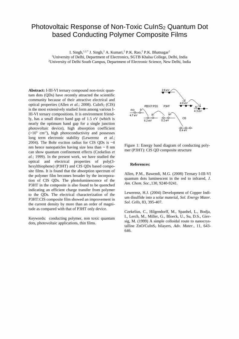
optical properties (Allen et al.; 2008). CuInS2 (CIS)
is the most extensively studied form among various I-
III-VI ternary compositions. It is environment friend-
ly, has a small direct band gap of 1.5 eV (which is
nearly the optimum band gap for a single junction
photovoltaic device), high absorption coefficient
(>105 cm-1), high photoconductivity and possesses
long term electronic stability (Lewerenz et al.;
2004). The Bohr exciton radius for CIS QDs is ~4
nm hence nanopaticles having size less than ~ 8 nm
can show quantum confinement effects (Czekelius et
al.; 1999). In the present work, we have studied the
optical and electrical properties of poly(3-
hexylthiophene) (P3HT) and CIS QDs based compo-
site films. It is found that the absorption spectrum of
the polymer film becomes broader by the incorpora-
tion of CIS QDs. The photoluminescence of the
P3HT in the composite is also found to be quenched
indicating an efficient charge transfer from polymer
to the QDs. The electrical characterization of the
P3HT:CIS composite film showed an improvement in
the current density by more than an order of magni-
tude as compared with that of P3HT only device.
Keywords: conducting polymer, non toxic quantum
dots, photovoltaic applications, thin films.
Figure 1: Energy band diagram of conducting poly-
mer (P3HT): CIS QD composite structure
References:
Allen, P.M., Bawendi, M.G. (2008) Ternary I-III-VI
quantum dots luminescent in the red to infrared, J.
Am. Chem. Soc.,130, 9240-9241.
Lewerenz, H.J. (2004) Development of Copper Indi-
um disulfide into a solar material, Sol. Energy Mater.
Sol. Cells, 83, 395-407.
Czekelius, C., Hilgendorff, M., Spanhel, L., Bodja,
I., Lerch, M., Miller, G., Bloeck, U., Su, D.S., Gier-
sig, M. (1999) A simple colloidal route to nanocrys-
talline ZnO/CuInS2 bilayers, Adv. Mater., 11, 643-
646.

Benefits of a compact TiO2 layer for the elaboration of transparent TiO2 nanotubes array on conducting glass
A. Krumpmann, A. Decroly
Department of Materials Science, Faculty of Engineering, University of Mons, Mons, Belgium
Abstract: Titania nanotubes obtained by the ano-
dization method have received much attention due to
numerous possible fields of application including
sensors, photocatalysis or photovoltaics. Anodization
is classically performed on Ti foils but for photovol-
taic applications, the TiO2 nanotube array layer has to
be elaborated on a transparent substrate such as
transparent conducting oxide (TCO) coated glass.
Therefore a metallic Ti layer is sputtered on TCO
and then anodized to be converted to a transparent
TiO2 nanotube array (TNA) layer (figure 1). We de-
scribe the impact of introducing an additional com-
pact TiO2 layer under the metallic Ti layer during the
sputtering deposition and compare morphological
and optical properties of titania nanotubes films made
with and without this intermediate compact layer.
These results show considerable improvements in the
TNA layer macroscopic homogeneity when a com-
pact layer is used. They are attributed to the limita-
tion of an undesirable reaction of oxygen evolution
that takes place preferentially at the TCO-electrolyte
interface during anodization, causing a destructu-
ration of the TNA layer. Thus, using a TiO2 compact
layer allows a better control of the anodization pro-
cess and the transparency of the TNA layer in the
visible range is also increased. Furthermore, for solar
cell applications, the compact layer can act as a
blocking layer which is a common way to reduce
charge recombination.
Keywords: Titanium dioxide, thin films, nanotubes,
1-D nanostructures, anodization, solar cell applica-
tions.
Figure 1: Scanning electron microscopy image of a
1 µm thick TiO2 nanotube array film on TCO glass
with an intermediate compact TiO2 layer of approx-
imately 50 nm.

Study of LiFePO4 thin films as Li-ion battery cathode by in-situ
electrochemical atomic force microscopy in aqueous electrolyte
J. X. Wu, G. Y. Shang*
School of Physics, Beihang University, Beijing 100191, P. R. China
Abstract:
Lithium-ion (Li-ion) batteries have been widely used
as power sources for portable and mobile applica-
tions (Armand et al., 2008). In order to prolong bat-
tery life, it is important to study the mechanisms that
make battery capacity reduce with aging. Published
results have show that morphological changes occur
in aged cathodes. In this study, in-situ electrochemi-
cal atomic force microscopy (EC-AFM) that is com-
bined atomic force microscopy with electrochemical
methods was used to investigate morphological
changes of LiFePO4 thin film electrodes during
charge and discharge processes in real time under
aqueous environment (Demirocak et al., 2014;
Ramdon et al., 2014). LiFePO4 thin films were pre-
pared by depositing them on Au/Si substrate using
radio frequency magnetron sputtering deposition
method. The films were firstly characterized by X-ray
diffraction, and results showed that them were com-
posed of LiFePO4 phase with olivine structure. The
SEM and AFM results show that the average size of
particle was ~100 nm. The electrochemical perfor-
mance of the film electrodes in Li2SO4 aqueous elec-
trolyte was investigated by cyclic voltammetry. The
lithium ion diffusion coefficient of the film electrode
was estimated to be 2.31×10⁻⁷ cm2s-1, which is larger
than that of LiFePO4 powder of 5.53×10⁻⁸. The de-
crease and increase in the size of the LiFePO4 parti-
cles during charge and discharge were directly ob-
served by EC-AFM, and relevant mechanism is dis-
cussed.
Figure 1: EC-AFM images show that the changes in
the size of the LiFePO4 film electrode during charge
and discharge in the aqueous electrolyte.
References:
Armand, M.; Tarascon, J-M. (2008), Building better
batteries, Nature, 451, 652-657.
Demirocak, D. E.; Bhushan, B. (2014), In situ atomic
force microscopy analysis of morphology and parti-
cle size changes in Lithium Iron Phosphate cathode
during discharge, J. Colloid Interface Sci., 423, 151-
157.
Ramdon, S.; Bhushan, B.; Nagpure, S. C. (2014), In
situ electrochemical studies of lithium-ion battery
cathodes using atomic force microscopy. J. Power
Sources, 249, 373-384.

Textured fabrication of CdS/CdTe thin film PV cell with back contacts
Murugaiya Sridar Ilango1, 2, Sheela K Ramasesha1,*
1Indian Institute of Science, Divecha Centre for Climate Change, Bangalore, Karnataka, India 2Department of Physics, Jain University, Bangalore, Karnataka, India
Abstract: The basic function of a Solar cell is to
absorb sunlight and convert light energy into
electricity. The energy obtained is carbon free
renewable source of energy without any moving part.
The principle of solar cell came into lights when the
great scientists Chapin, Pearson, and Fuller prepared
a photovoltaic effect using poly-Si in 1954. Since
silicon semiconductor technology was so widely
studied, for more than 40 years solar cells were
fabricated using silicon crystals . As a replacement for
silicon, materials which can be used are amorphous
silicon, CdTe, Cu (In, Ga) Se2, InP, CdSe and GaAs.
Thin film solar cells are considered to be large area
diodes, to increase the absorption of light and reduce
the cost of fabrication. Electron-hole pairs are
generated by the absorbed photons, the electric energy
is formed when the excited carrier is swept across the
potential field. The voltage generated during the
separation of opposite charge helps in driving the
current through external electric circuit. In a
CdS/CdTe based solar cell the potential field or the
depletion layer is formed at the interface of the CdS
and CdTe layers. In this paper CdS is the window
layer which has a wide band gap of 2.45 eV which
allows most of the light to the absorber layer CdTe
with a band gap of 1.45 eV. Photons from the sunlight
are absorbed only when the energy is higher than the
band gap of the absorber layer. Thin film Solar cells
have a record efficiency of 19.6%, and commercially
available CdTe PV panels of 12% (Green, et al.,
2013). The loss due to reflection has limited all types
of solar cells to a great extent. Hence, one method of
trapping the light for more absorption is through nano-
texturing of junction area. In commercial thin-film
CdTe solar panels 4% of its energy is already reflected
in the glass-air interface of the modules (Kaminski, et
al., 2014). Nanostructuring of silicon has produced
extensive research in solar cell application because of
its low reflectance and enhanced light trapping
technique (Oelhafen, et al., 2005). Along with the
texturing of junction area, the concept of back contact
is taken into account (Figure 1). As the front contact
in a solar cell transmits only 50% of the solar radiation
(Fan, et al., 2009), back contact research started after
the publication of R.J Schwartz in 1975 as a substitute
for cells which has front and rear contacts. The metal
grids with narrow, closely packed metal lines can
reduce series resistance (Dean, et al., 1975) but
increases blockage of sunlight (by reflecting). As the
front and rear contacts are placed at the rear surface,
increases the packaging density of the panel and also
gives raise to performance gain (Kerschaver, et al.,
2006). So the performance of back contact solar cell
is to be tested along with the increased junction area
by texturing the interface surface.
Keywords: textured solar cell, back contact,
CdS/CdTe, nanowall design, thin flim PV.
Figure 1: SEM image of Nano wall structure (Surface
morphology)
References:
Dean R. H., Napoli L. S. and Liu S. G. (1975) Silicon solar
cells for highly concentrated sunlight, RCA Review, 36, 324-335.
Fan Zhiyong [et al.] (2009)Three dimensional nanopillar
array photovoltaics on low cost and flexible substrates,
nature materials, 8, 648-653.
Green Martin A. [et al.] (2013) Solar cell efficiency tables
(version 42), Progress in Photovoltaics: Research and
Applications, 21, 827-837.
Kaminski P. M., Lisco F. and Walls J. M. Multilayer (2014)
Broadband Antireflective Coatings for More Efficient Thin
Film CdTe Solar Cells, IEEE Journal of Photovoltaics, 4,
452-456.
Kerschaver Emmanuel Van and Beaucarne Guy
(2006)Back-contact Solar Cells: A Review, Progress in
Photovoltaics: Research and Applications, 14,107-123.
Oelhafen P. and Schuler A. (2005) Nanostructured materials for solar energy conversion, Solar Energy, 79,110-121.

Nonradiative Electron and Hole Relaxation Dynamics in Organometallic Halide Perovskites
M.E. Madjet,1 F. El-Mellouhi,1, , G. Berdiyorov1, S. Ashhab1 A. Akimov2 and S. Kais1
1Qatar Environment & Energy Research Institute, Qatar Foundation, PO Box 5825, Doha, Qatar 2Department of Chemistry, University of Southern California, Los Angeles, CA 90089
Abstract: Hybrid organic-inorganic perovskites, such as methylammonium (MA) lead iodide (CH3NH3PbI3 or MAPbI3), are promising new ab-sorber materials for solar energy applications that have attracted significant interest in the last few years. Solar conversion efficiencies of more than 19% have been reported for these materials [1]. This high efficiency is mainly due the long diffusion lengths of charge carriers, low sensitivity to defects and high mobility of charge carriers. However, many fundamental processes related to the photophysics of these materials remain not fully understood. The excitation of electrons from the valence band to conduction band results in the formation of hot elec-trons and holes, both of which lose most of their en-ergy by cooling down to the band edges. Extracting hot carriers before they thermalize towards the re-combination would lead to higher efficiency. Conse-quently, simulating the relaxation dynamics of pho-toexcited charge carriers is of great importance for further optimization of photovoltaic devices. In order to understand in more detail the process of charge carrier dynamics in peroveskite materials, a theoretical description based on time-domain meth-ods is required to enable shedding light on recent experimental finding on electron and hole relaxation dynamics [2] and also to guide future experimental investigations. A mixed quantum-classical approach based on trajectory surface hopping is used to de-scribe the dynamics of hot charge carriers. In this approach, the electrons are described quantum me-chanically by solving the Schroedinger equation and the nuclear degrees of freedom are propagated by independent classical trajectories, which are com-puted by solving the classical Newton’s equations. In this contribution, we address the non-radiative relaxation process of electrons and holes in organo-metallic perovskite CH3NH3PbI3 when electrons are promoted to the conduction band from the valence-band. We perform nonadiabatic molecular dynamics simulations using the combination of the PYthon eXtension for Ab Initio Dynamics [3] package for quantum dynamics simulations interfaced with the Quantum Espresso electronic structure code. Our aim is to get a fundamental understanding of the intra-band relaxation process of hot electrons (holes) to the minimum (maximum) of the conduction (valence) band and how these processes are affected by perov-skite composition and structure. Results on the per-
ovskite materials CH3NH3PbI3, CH3NH3PbBr3, CH3NH3PbCl3, CH3NH3PbI3-xBrx and CH3NH3PbI3-
xClx will be presented. The electron relaxation time values obtained from our simulation for CH3NH3PbI3 are in good agree-ment with the experimental data reported in Ref. [2]. We also found that halogen-mixing CH3NH3PbI3-xClx results in slowing down the elec-tron and hole relaxation process, suggesting a longer life time in Cl-doped systems. Keywords: Photovoltaic, perovskite, electron/hole transport, nonradiative carriers relaxation, nonadi-abatic dynamics, surface hopping.
References:
[1] National Renewable Energy Laboratory, Best Research-Cell Efficiencies; www.nrel.gov/ncpv/images/efficiency chart.jpg
[2] Hung-Yu Hsu et al, Angew.Chem. Int. Ed. 53, 1 (2014).
[3] A.V. Akimov and O.V. Prezhdo, J. Chem. Theory Comput. 9, 4959 (2013).

C-Nanotube Based Infrared Thermo-Voltaic Cells and Detectors
T.Hosseini, N.Yavarishad and N. Kouklin
Dept. of Electrical Engineering, Univ. of Wisconsin-Milwaukee,P.O. Box 413 Milwaukee, WI, 53201, USA
Abstract: Sun radiation remains a key renewable energy source, with ~40% of its energy falling into the infrared part of the EM spectrum. This low grade energy, while available is thinly stretched over a relatively broad spectral win-dow of ~ 0.7-3 μm. For a p-n junction based photovoltaic (PV) solar cell, a maximum vol-tage is limited by Voc≅ Eg/e, where e stands for the unit charge. For ideal cells, the conversion efficiency is to scale linearly with Eg given by 𝜒𝜒 (𝜆𝜆)~ 1
𝜆𝜆~ 𝐸𝐸𝑔𝑔 .[1] As the fabrication and
deployment costs are to be on par with those of existing PV systems, IR-PV cells that inherit conventional design are to demonstrate at least order of magnitude lower efficiency-to-cost ra-tio. While several concepts were offered to harvest IR-sun radiation including antenna ar-rays and quantum dots, with their spectrally-broad absorption spectrum and the fabrication cost that has fallen precipitously, single-walled carbon nanotubes can pave a way to the devel-opment of indirect-type, cost-efficient photo-thermo-voltaic (PTV) cells.
Herein, we engineer and test two-terminal car-bon nanotube photocells for the purpose of infrared photo-thermo-electric energy conver-sion and sensing. The photo-voltage and nonze-ro conversion efficiency were found to appear only for off-center illumination which can be explained within photo-generated heat flow model and not the contact effects. [2] Under incident optical powers of ca. 450 mW, the equivalent short-circuit current, ISC, and open-circuit voltage, VOC, stood at ca. 0.2 uA and ca. 0.5 mV, respectively. The cell prototypes yielded ~ 30 nW of electrical power that typical-ly followed non-monotonic dependence on the incident light power given by Pout max~ β
inP , where 08.1=β . As the PTV cell can also uti-lized as IR-photosensor, its transient response was probed by carrying out off/on photocurrent tests at varied temperatures: 123, 253 & 300 0K. The photo-current, Iph decayed with
-1.8x10⁻⁷ -9.0x10⁻⁸ 0.0
0.0
2.0x10⁻⁸
4.0x10⁻⁸
0.0 0.3
-0.2
0.0
dark 49 mW 186 mW 329 mW 453 mW
Cur
rent
, uA
Voltage, mV
Gen
erat
ed P
ower
, WCurrent, A
time as single exponential Iph ~ 1 − 𝑒𝑒−𝑡𝑡/𝜏𝜏 and the characteristic decay constant,τ was found to change linearly with I-1
dark confirming that the transient respose is controlled by device circui-try and not heating/cooling processes. The con-cept might enable engineering and implementa-tion of the carbon nanotube based PVT devices for application in heat recycling and self-powered infrared detectors. Keywords: infared, carbon, nanotubes, photovoltaic, sensors, cell.
Figure 1: Showing power vs. current characteristic of the PTV cell obtained at RT and incident power of ~ 450 mW. The inset shows I-Vs for different
References:
[1] S.M.Sze, “Semiconductor Devices”, J.Willey and Sons, 2nd edition (2002) [2] T. Hosseini, M. Omari. and N. Kouklin, Electr. Dev. Letters, 34 , 7 , 924-926 (2013)

Natural Biodefensive Nanoparticles for Pest Control in Soy Culture
A.L. Santos,1* V. Zucolotto,1,2 B.T.R. Rhein,1 I. Pezzopane,1 G.Rosa1
1Nanomed Inc., São Carlos, Brazil 2University of São Paulo, Laboratory of Nanomedicine and Nanotoxicity, São Carlos, Brazil
Abstract: Nanomed Inc. has been developing a new methods for natural compounds controlled delivery system. A polymeric nanoparticle obtained via sol-vent evaporation is a new approach to delivery a nat-ural and reactive compound to improve the treatment in soy culture, the most important culture in Brazil. This is a bioactivity essential oil against insects and other pests, flavoring agent used in cosmetic and food products however it was previously reported to have a skin- sensitizing ability and to cause allergic reactions (ATSUMI; FUJISAWA; TONOSAKI, 2005; MURRAY B. ISMAN, 2006). In spite of huge bioactivity, its reactivity and volatility reduce the action time. So, a controlled delivery system was developed, changing the surface area which may influence its toxicity. The nanoparticles cytotoxicity was evaluated in L929 fibroblasts, against a negative control and literature. The enhancement of the natural active by encapsula-tion was able to protect it from oxidative degrada-tion, and improve their fungicidal activity (GARG; SINGH, 2011). We observe that these nanoparticles showed a similar behavior even in different delivery system (polymer). However with the concentration increase, there is the decrease of toxicity, with the higher viability in fibroblasts. Based on the different concetrations stud-ies, it is possible to conclude that the cytotocity is not dose dependent. However, one notice the increase in the cellular apoptosis as the nanoparticle size de-creases. So, the nanotoxicity is directly linked to the size of nanoparticle, and not related to the essential oil concentration. Keywords: biodefensive, polymeric nanoparticles, natural-based material, cytotoxity, pest control, soy culture, agribusiness applications.
Figure 1: Figure of natural compound nanoparticles cytotoxicity in a different controlled delivery sys-tem, at 0.1 ppm concentrations. Samples: 1- PLA- natural compound 0.5%; 2- PCL- natural compound 1%; 3- PLA- natural compound 1%.
References:
ATSUMI, T.; FUJISAWA, S.; TONOSAKI, K. A comparative study of the antioxidant/prooxidant activities of eugenol and isoeugenol with various concentrations and oxidation conditions. Toxicology in vitro, v. 19, n. 8, p. 1025–33, dez. 2005.
GARG, A; SINGH, S. Enhancement in antifungal activity of eugenol in immunosuppressed rats through lipid nanocarriers. Colloids and surfaces. B, Biointerfaces, v. 87, n. 2, p. 280–8, 15 out. 2011.
MURRAY B. ISMAN, C. M. M. Pesticides based on plant essential oils: from traditional practice to commercialization. In: CARPINELLA, R. AND (Ed.). . Naturally Occurring Bioactive Compounds. [s.l.] Elsevier, 2006. p. 29–44.

Sol-Gel Production and Electrochemical Characterization of
Free-Standing Metal Oxide/MWCNT Nanocomposite Anodes for
Li-Ion Batteries
H. Köse, Ş. Karaal, A. O. Aydın, H. Akbulut
Sakarya University, 54187, Sakarya, Turkey
Abstract: Lithium ion batteries (LIBs) are one of the
most promising candidates for electrochemical ener-
gy conversion and storage devices, in the scientific
and industrial fields, with one of the best energy den-
sities (Wang et al.; 2006). Zinc and tin dioxide based
materials are being used as active anode materials for
rechargeable lithium batteries, because the theoretical
capacity of ZnO (978 mAhg-1
) and SnO2 (1491
mAhg-1
) has been estimated to be superior to that of
graphite (372 mAhg−1
) (Guler et al.; 2014, Ning et
al.; 2008). High capacity anodes such as zinc and tin
based usually suffer severe capacity fading, because
of the quick aggregation of metal particles and the
huge volume expansion during Li+ inser-
tion/extraction cycles (Huang et al.; 2011). To pre-
vent the pulverization of the anodes and electrical
detachment of active materials, MWCNT buckypaper
substrates are considered as a buffer material during
the battery applications (Guler et al.; 2014). In this
work, ZnO/MWCNT and SnO2/MWCNT buckypa-
per nanocomposite films were prepared as free-
standing anode materials by sol–gel spin coating.
Structural properties and electrochemical perfor-
mances of metal oxides/MWCNT nanocomposite
anodes were investigated and compared. As can be
seen from Figure 1, it was aimed to accommodate the
stresses arisen from the volume increase during
charging process by using highly porous MWCNT
network that coated with a thin layer of the metal
oxides (MO). The structural properties of free-
standing buckypaper composite film anodes were
characterized by FEG-SEM (Field Emission Gun -
Scanning Electron microscopy), TEM (Transmission
Electron Microscopy), EDS (Energy Dispersive X-
ray Spectroscopy) and XRD (X-ray Diffraction)
tehcniques. Electrochemical performance tests, CV
(Cyclic Voltammetry) and EIS (Electrochemical
Impedance Spectroscopy) analyses of free-standing
anodes of CR2016 type Li-ion batteries were also
performed. The cells were charged and discharged at
25 °C between fixed voltage limits (2.5 V to 0.2 V).
Keywords: Li-ion battery applications, metal ox-
ide/MWCNT nanocomposite anodes, sol-gel synthe-
sis, spin coating method, structural and electrochemi-
cal characterization.
Figure 1: The illustration of the production of free-
standing Metal Oxide/MWCNT anodes.
References:
Guler, M.O., Cetinkaya, T., Tocoglu, U., Akbulut, H.
(2014), Electrochemical performance of MWCNT rein-
forced ZnO anodes for Li-ion batteries, Microelectronic
Eng., 118, 54–60.
Huang, X.H., Xia, X.H., Yuan, Y.F., Zhou, F. (2011),
Porous ZnO nanosheets grown on copper substrates as
anodes for lithium ion batteries, Electrochim. Acta, 56,
4960-4965.
Ning, Y., Jianhua, W., Yuzhong, G., Xiaolong, Z. (2008),
SnO2 Nanofibers Prepared by Sol-Gel Template Method ,
Rare Metal Mater. Eng., 37, 694-696.
Wang, Y., Su, F., Lee, J.Y., Zhao, X.S. (2006), Crystalline
Carbon Hollow Spheres, Crystalline Carbon−SnO2 Hollow
Spheres, and Crystalline SnO2 Hollow Spheres: Synthesis
and Performance in Reversible Li-Ion Storage, Chem. Ma-
ter., 18, 1347-1353.
The Effect of Different Solvent Combination of LiBF4
Electrolyte on Free-Standing SnO2/MWCNT Nanocomposite
Anode Capacity for Li-ion Batteries
Ş. Karaal, H. Köse, A. O. Aydın, H. Akbulut
Sakarya University, 54187, Sakarya, Turkey
Abstract: Owing to their high energy density, lit-
hium-ion batteries are widely used in portable elect-
ronics (Xiang et al.; 2009). With a wide optical band
gap (3.6 eV) tin dioxide is an n-type semiconductor
material. For rechargeable lithium batteries, tin and
tin oxide based materials are being used as active
anode materials (Kose et al.; 2013). However, during
Li+
insertion/extraction cycles, anodes of such high
capacity usually suffer severe capacity fading result-
ing from both the huge volume change and the quick
aggregation of tin particles (Zhang et al.; 2009).
MWCNT buckypaper substrates are considered as a
buffer material during the battery applications in or-
der to prevent the pulverization of the anodes and
electrical detachment of active materials (Kose et al.;
2013). For commercial Li-ion cells, the typical non-
aqueous electrolyte is a solution of LiPF6 in linear
and cyclic carbonates such as dimethyl carbonate and
ethylene carbonate, respectively (Kerr et al.; 2003).
Compared with LiPF6, LiBF4 has some advantages
such as better thermal stability and lower sensitivity
toward environmental moisture and its solution pro-
vides lower charge-transfer resistance, especially at
low temperatures (Zhang et al.; 2006).In this work,
free-standing SnO2/MWCNT nanocomposite was
used as anode, metallic Li as cathode and 1 molal
LiBF4 solution as electrolyte. It was aimed to deter-
mine the optimum ratio of Ethylene Carbonate
(EC):Dimethyl Carbonate (DMC) solvents in 1 molal
LiBF4 electrolyte solutions for high capacity
SnO2/MWCNT buckypaper anode. Different EC :
DMC (2:1, 1:1 and 1:2) solvent combinations were
prepared in a glove box. For these electrolyte solu-
tions, conductivity tests were applied. Structural
properties and electrochemical performances of
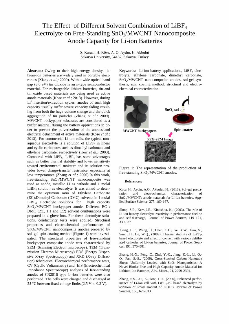
SnO2/MWCNT nanocomposite anodes prepared by
sol–gel spin coating method (Figure 1) were investi-
gated. The structural properties of free-standing
buckypaper composite anode was characterized by
SEM (Scanning Electron microscopy), TEM (Trans-
mission Electron Microscopy) EDS (Energy Disper-
sive X-ray Spectroscopy) and XRD (X-ray Diffrac-
tion) tehcniques. Electrochemical performance tests,
CV (Cyclic Voltammetry) and EIS (Electrochemical
Impedance Spectroscopy) analyses of free-standing
anodes of CR2016 type Li-ion batteries were also
performed. The cells were charged and discharged at
25 °C between fixed voltage limits (2.5 V to 0.2 V).
Keywords: Li-ion battery applications, LiBF4 elec-
trolyte, ethylene carbonate, dimethyl carbonate,
SnO2/MWCNT nanocomposite anodes, sol-gel syn-
thesis, spin coating method, structural and electro-
chemical characterization.
MWCNT buckypapers
FEG-SEM Image
Figure 1: The representation of the production of
free-standing SnO2/MWCNT anodes.
References:
Kose, H., Aydin, A.O., Akbulut, H., (2013), Sol–gel prepa-
ration and electrochemical characterization of
SnO2/MWCNTs anode materials for Li-ion batteries, App-
lied Surface Science, 275, 160-167.
Sloop, S.E., Kerr, J.B., Kinoshita, K., (2003), The role of
Li-ion battery electrolyte reactivity in performance decline
and self-discharge, Journal of Power Sources, 119–121,
330-337.
Xiang, H.F., Wang, H., Chen, C.H., Ge, X.W., Guo, S.,
Sun, J.H., Hu, W.Q., (2009), Thermal stability of LiPF6-
based electrolyte and effect of contact with various delithi-
ated cathodes of Li-ion batteries, Journal of Power Sour-
ces, 191, 575–581.
Zhang, H.-X., Feng, C., Zhai, Y.-C., Jiang, K.-L., Li, Q.-
Q., Fan, S.-S., (2009), Cross-Stacked Carbon Nanotube
Sheets Uniformly Loaded with SnO2 Nanoparticles: A
Novel Binder-Free and High-Capacity Anode Material for
Lithium-Ion Batteries, Adv. Mater., 21, 2299-2304.
Zhang, S.S., Xu, K., Jow, T.R., (2006), Enhanced perfor-
mance of Li-ion cell with LiBF4-PC based electrolyte by
addition of small amount of LiBOB, Journal of Power
Sources, 156, 629-633.
SnO2 sol
Spin coater

Photocatalytic Activities of ZnO and ZnO/ZnS Synthesized by
Microwave-Hydrothermal Method
N. Güy,1*
Şeref Durmuş1, M. Özacar,
1
1Sakarya University, Department of Chemistry, Sakarya, Turkey
Abstract: Because of the diffussing of toxic and col-
oured wastewater into water sources, dyes have a bad
effect on the nature of water like inhibitting sunlight
penetration and reducing photosynthetic reaction.
(Hu et al.; 2011). The techniques which are used for
the treatment of dye waste effluents are usuallyare
usually inefficient, non-destructive and costly. (Jia et
al.; 2013). Heterogeneous semiconductor photocata-
lysts such as ZnO have an important role for the re-
moval of dye pollutants from water. ZnO semicon-
ductor has a wide bandgap energy of 3.37 eV and a
relatively large exciton binding Energy (60 meV),
thus can absorb only UV light with the wavelength
equal to or less than 385 nm. But solar spectra con-
tain only approximately 3%–5% UV light; therefore,
the great mass of solar photons is useless for ZnO
photocatalyst, which greatly limits its environmental
applications (Ma et al.; 2011). The photocatalytic
performance of ZnO can be improved by modifica-
tion due to inhibit recombination of photogenerated
electron-hole pairs. The band gap of ZnS (3.68 eV) is
larger than that of ZnO, experimental results have
demonstrated that the combination of these two wide
bandgap semiconductors could yield a novel compo-
site with the photo excitation threshold energy lower
than those of the individual components (Ma et al.;
2013). In the present study, ZnO/ZnS nano photo-
catalysts were synthesized by microwave-
hydrothermal method using different precursors as
Sulfur source. The prepared photocatalysts were
characterized by X-ray diffraction (XRD), field emis-
sion scanning electron microscopy (FESEM) and
UV–visible (UV–vis). The photocatalytic activities
samples and undoped ZnO have been studied for the
degradation of dye, and have also been compared
with together.
.
Keywords: Synthesis, photocatalyst, ZnO/ZnS, deg-
radation
Figure 1: Kubelka-Munk transformed reflectance
spectra of ZnO/ZnS
References:
Hu, Y., Qian, H., Liu, Y., Du, G., Zhang, F., Wang,
L., Hu, X.(2011), A microwave-assisted rapid route
to synthesize ZnO/ZnS core–Shell nanostructures via
controllable surface sulfidation of ZnO nanorods,
CrystEngComm., 13, 3438-3443.
Jia, W., Jia, B., Qu, F., Wu, X., (2013), Towards a
highly efficient simulated sunlight driven photoca-
talyst: a case of heterostructured ZnO/ZnS hybrid
structure, Dalton Trans., 42, 14178-14187.
Ma, H., Han, J., Fu, Y., Song, Y., Yu, C., Dong, X.,
(2011), Synthesis of visible light responsive ZnO–
ZnS/C photocatalyst by simple carbothermal reduc-
tion, Applied Catalysis B: Environmental 102, 417–
423.
Ma, H., Cheng, X., Ma, C., Dong, X., Zhang, X.,
Xue, M., Zhang, X., Fu, Y., (2013), Synthesis, Cha-
racterization, and Photocatalytic Activity of N-Doped
ZnO/ZnS Composites, International Journal of Pho-
toenergy, 2013, 8 pages.

Polystyrene Micro/Nanofibers and its Application in the Removal of Crude Oil Spills
M. Alazab Alnaqbi1,*, Afra Al Blooshi1, Yaser. Greish1, and Mahmoud Mohsin2
1Department of Chemistry, United Arab Emirates University, Al Ain, United Arab Emirates 2Department of Chemistry, University of Sharjah, Sharjah, United Arab Emirates
Abstract: Water pollution by crude oil has major environmental impact worldwide (M. Al-Azab et al. 2005). The great concern of the global community on the unfavorable and longstanding effects of spilt oil on ecosystems, created a vital need to develop materials for effective oil spill clean-ups (Xia, Y. Q et al. 2010). This work aimed to study the effective-ness and applications of PS polymer in clean-up of crude oil from oil spills. Molecular weights of the fibrous polystyrene precur-sors, were in the range of 100,000 – 350,000 Dalton. Fibers were used for the removal of crude oil spills in seawater. Due to the hydrophobic nature of both the fibers and the crude oil, the later was instantly ab-sorbed onto the fibers achieving a maximum sorption capacity of 220 g of crude oil per each gram of fiber. Nano/Microfibers of polystyrene was prepared by electrospinning technique (Haitao Zhu et al. 2011). Fibers with a size range of 500 nm- 8 µm in diameter and below 100 m2/g in surface area were prepared after a thorough optimization of the electrospinning process. Fibers prepared were tested for their oil absorption efficiency as a function of absorbent weight, time of absorption, and initial concentration of the polymer solution prior its conversion to fibers. Results showed an initial sorption capacity of a range of 60-200 g/g with microfibers prepared from 20% PS solution. The surface area of the produced fibers varied based on fiber size distribution, which depends on varia-tions in the electrospinning parameters. Hence, opti-mizations of the process were studied to achieve con-sistency in the fiber size distribution, and the surface area of the fibers as well. Results showed the im-portance of the high surface area and interconnectivi-ty of the porosities within the PS microfibrous sorbent for the removal of the oil, making the micro-fibrous PS sorbents an excellent candidate for crude oil spill cleanup. Keywords: nanofibers, polystyrene, crude oil, elec-trospinning
Figure 1: SEM image for electrospun PS fibers with mesoporosity and different size distribution. Poly-styrene was dissolved in the proper solvent forming solutions of 20, 30, and 40 wt%. Electrospinning process conditions were optimized at a voltage of 20 kV, a feeding rate of 10 ml/hr, and a distance of 15 cm. Due to the high viscosity of the crude oil, their flow within the fibrous sorbent during the process of removal will be limited and requires macroporosity for a more efficient sorption and impregnation within the fibrous sorbent. The produced microfibers con-tained macroporosity by virtue of the interlocking between the fibers within the electrospun fibrous mesh.
References: M. Al-Azab, E. El-Shorbagy and S. Al-Ghais (2005). Proceedings of the International Conference on "Oil Pollution and it Environmental Impact in the Arabian Gulf Region". Elsevier, ISBN: 978-0-444-52060-9. Xia, Y. Q.; Boufadel, M. C. (2010) Lessons from the Exxon Valdez oil spill disaster in Alaska. Disaster Adv, 3 (4), 270−273
Haitao Zhu, Shanshan Qiu, Wei Jiang, Daxiong Wu, and Canying Zhang (2011), Evaluation of Electro-spun Polyvinyl Chloride/Polystyrene Fibers As Sorbent Materials for Oil Spill Cleanup, Environ. Sci. Technol, 45, 4527–4531

Effects of biopolymer nano coils on sand dune stabilization and dust
controlling
M. Aghaei Moghadam1*, K. Zangeneh2 1 Biopolynet Inc, Fredericton, NB, Canada
2 Biopolynet Inc, Fredericton, NB, Canada
*Email: [email protected]
Abstract
Despite the large history and popularity of sand/dune stabilization in exploratory research, a unique
method with large-scale applications has yet to be realized. The main impediments reside in the
methods of the stabilizations currently in use, at the moment (a) no specific technology is available,
(b) a particular stabilizer is necessary for each specific condition, (c) most products just stabilize the
surface of sand dunes and (d) most applications require a long time to be fixed in large quantities
in a predetermined and controllable fashion. Designing biopolymeric networks with controlled
size and desirable properties is the best way to fix sand dune and dust. Thus we hereby describe a
novel view and simple method to stabilize sand/dunes by designing a novel aqueous biopolymer
coils system to spray on the sand/dune surface in order to make a network with sand/dune agents
by penetration of aqueous biopolymer into the sand dune.

Carboxymethyl-nanocellulose:a versatile raw-material in coating industry
A. Reis,
1,* R. Duarte,
1 J. Tedim,
2 A. Caetano,
2 A.P. Mendes de Sousa,
3 J. Ataíde,
3 D. Evtuguin
1
1CICECO-Aveiro Institute of Materials, Department of Chemistry, University of Aveiro, 3810-193 Portugal
2CICECO-Aveiro Institute of Materials, Department of Materials and Ceramic Engineering, University of Avei-
ro, 3810-193 Portugal 3RAIZ, grupo PORTUCEL/SOPORCEL, 3801-501 Eixo, Portugal
Abstract: Cellulose is the most abundant polysac-
charide and widespread biopolymer in nature. For
this reason, cellulose and its derivatives are very at-
tractive for the manufacture of sustainable biobased
materials. Unlike cellulose, functionalized cellulose
with carboxymethyl groups (CMC) is water soluble
exhibiting a multitude of applications as gelling agent
in food industry, as paint thickeners in coating indus-
try and film packaging in food and paper industry
(Klemm et al., 2005). Aside from its mechanical and
water retention properties, the biocompatibility ex-
hibited makes CMC a promising option as a support
of biomolecules with chemical and biological activity
for the development of biosensors and wound dress-
ings (Carlsson et al., 2014). However, commercially
available CMC powders have high degrees of substi-
tution (DS) ranging between 0.5-1.2 and a high den-
sity of anionic charged groups by the presence of
surface carboxylic groups. The high surface negative
charge has a deleterious impact on the stability of the
incorporated biomolecules (Carlsson et al., 2014) and
even affecting the release behavior of incorporated
drug (Valo et al., 2013).
In this study, we have synthetized CMC with various
degrees of substitution (DS) using environment-
friendly aqueous conditions. The functionalized
CMC pulp with DS<0.2 was submitted to ultraho-
mogenization resulting in high quality carboxymethyl
nanocellulose (NC) suspensions (over 90% of nano-
fibrils) through a energy-efficient process(energy
reduction of >60% compared to unmodified NC).
The carboxymethyl-NC films prepared by solvent
casting exhibited improved optical and morphologi-
cal properties whilst retaining the mechanical proper-
ties in the temperature range (-50 to 200C) studied.
Preliminary results obtained by electrochemical im-
pedance spectroscopy (EIS) using functionalized
nanocellulose in solution and as additives to protec-
tive coatings have shown improved anti-corrosion
performance in coated substrates. The increased hy-
drophobicity and zeta potential of prepared CMC
suspensions reveal great potential for industrial coat-
ing and will be further explored on the adsorption of
molecules for biomedicine applications.
Keywords: carboxymethyl cellulose, transparent
films, corrosion inhibitors, biomedical applications.
References:
Klemm, D., Heublein, B., Fink, H.P., Bohn, A.
(2005) Cellulose: fascinating biopolymer and sus-
tainable raw material, Angew. Chem. Int., 44, 3358-
3393.
Valo, H., Arola, S., Laaksonen, P., Torkkeli, M.,
Peltonen, L., Linder, M.B., Serimaa, R., Kuga, S.,
Hirvonen, J., Laaksonen, T. (2013), Drug release
from nanoparticles embedded in four different nano-
fibrilar cellulose aerogels, Eur. J. Pharm Sci., 50, 69-
77.
Carlsson, D.O., Hua, K., Forsgren, J., Mihranyan, A.
(2014), Aspirin degradation in surface-charged
TEMPO-oxidized mesoporous crystalline nanocellu-
lose. Int. J. Pharma. 461, 74-81.
Acknowledgements
This work was developed in CICECO-Aveiro Insti-
tute of Materials and is funded by ERDF Funds
through Operational Competitiveness Programme –
COMPETE in the frame of the project NMC– QREN
34169.
Graphene Reinforced Concrete
M.F. Craciun, D. Dimov
University of Exeter, Exeter, Devon, United Kingdom
Abstract:
This work presents the revolutionary idea of bridg-
ing the international research on nanoscience with
traditional construction material concrete. The aim
of the project is to introduce graphene - an one at-
om thick layer of graphite with two-dimensional
properties, within the chemical matrix of cement.
The stand-out mechanical properties of graphene
such as very high ultimate tensile strength and re-
taining initial size after strain make it suitable for
applications in the construction industry. There are
two main liquid exfoliation methods of producing
surfactant-stabilized graphene dispersions in aque-
ous environment [2],[3]. The first one uses soni-
cation energy principles for breaking down layers of
graphite and the addition of surfactant (Sodium
Cholate) preserves all of their properties in water
[3]. The second uses high-shear exfoliation machine
which uses laws of turbulent forces to achieve even
better quaility flakes with more consistent rate of
dispersion [2]. The resultant solution from 48h of
sonication is mixed with Ordinary Portland Cement
(OPC), sand and aggregate to prepare standard
10x10x10cm concrete cubes for testing compres-
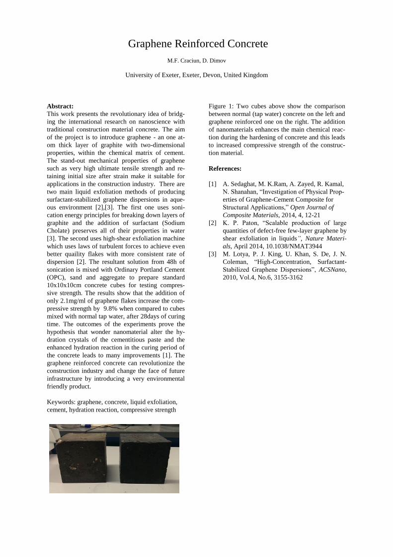
sive strength. The results show that the addition of
only 2.1mg/ml of graphene flakes increase the com-
pressive strength by 9.8% when compared to cubes
mixed with normal tap water, after 28days of curing
time. The outcomes of the experiments prove the
hypothesis that wonder nanomaterial alter the hy-
dration crystals of the cementitious paste and the
enhanced hydration reaction in the curing period of
the concrete leads to many improvements [1]. The
graphene reinforced concrete can revolutionize the
construction industry and change the face of future
infrastructure by introducing a very environmental
friendly product.
Keywords: graphene, concrete, liquid exfoliation,
cement, hydration reaction, compressive strength
Figure 1: Two cubes above show the comparison
between normal (tap water) concrete on the left and
graphene reinforced one on the right. The addition
of nanomaterials enhances the main chemical reac-
tion during the hardening of concrete and this leads
to increased compressive strength of the construc-
tion material.
References:
[1] A. Sedaghat, M. K.Ram, A. Zayed, R. Kamal,
N. Shanahan, “Investigation of Physical Prop-
erties of Graphene-Cement Composite for
Structural Applications,” Open Journal of
Composite Materials, 2014, 4, 12-21
[2] K. P. Paton, “Scalable production of large
quantities of defect-free few-layer graphene by
shear exfoliation in liquids”, Nature Materi-
als, April 2014, 10.1038/NMAT3944
[3] M. Lotya, P. J. King, U. Khan, S. De, J. N.
Coleman, “High-Concentration, Surfactant-
Stabilized Graphene Dispersions”, ACSNano,
2010, Vol.4, No.6, 3155-3162

Quantum Dot Sensitized Solar Cells with Cuprous Sulfide Counter Electrode
Nuno Marques Ferreira, César Bernardo, Isabel Moura, Paulo J. G. Coutinho, Anabela G. Rolo, Mikhail Vasi-
levskiy, M. Pastor, F. Fernandes, V. Teixeira, J.O.Carneiro, Anura Samantilleke*
Centro de Física, Universidade do Minho, Campus de Gualtar, 4710-057, Braga, Portugal
Abstract: Although, solution processing is a promis-
ing route for the realization of low-cost, large-area
devices with short energy payback time and high spe-
cific power, low-temperature fabrication conditions
and good atmospheric stability while maintaining a
high efficiency remains a major technical challenge.
However, the recent report of a certified efficiency of
8.55% for a ZnO/PbS Quantum dot (QD) solar cell
(SC) achieved by engineering the band alignment of
the QD layers through the use of different ligand
treatments promises the possibility of newapproaches
towards the goal of high-performance air-stable solar
cells compatible with simple solution processes (Chuang et al, 2014). CdSe QDs with an absorption onset in the red or near infrared are equally promis-ing (Kamat, 2008). In this work, QDSCs based on a
mesoporous structure of TiO2 and a polysulfide re-
dox electrolyte, were prepared by adsorption of col-loidal CdSe QD absorbers onto the photoanode, with and without linkers. CdSe/ZnS QDs were synthesized within aqueous pools of reverse micelles, based on standard wet chemistry methods, while al-kylphosphine oxide (TOPO) functionalized CdSe QDs were prepared by reactions of organo-metallic pre-cursors at high temperature. A chlorine surface treatment performed on TiO2 prior to sensitisation improved QD adsorption on the photoanode. An electrochemically deposited Cu2S/conducting glass (CTO), which has a higher tolerance to polysulfide electrolyte, was used as the counter electrode. The Cu2S film, composed of interconnected nanoflakes, showed good catalytic activity with the best SCs (ef-fective area 0.16 cm2) showing up to 2.13% conver-sion efficiency under AM1.5 illumination. The pho-tovoltaic characteristic of the solar cells was meas-ured using a calibrated solar simulator with 100 mW/cm2 irradiation (AM 1.5). The colloidal QDSC performance was primarily limited by a low fill factor of 0.45, which is believed to arise from charge trans-fer of photogenerated electrons to the aqueous electrolyte. This work was supported by the MATEPRO - NORTE-07-0124-FEDER-000037 and the European Commission through NanoCIS project (FP7/PIRSESGA-2010-269279), both of which are gratefully acknowledged.
Keywords: CdSe, quantum dot, solar cell, TOPO,
Cu2S
Presenting author’s email: [email protected]
Figure 1: Ressonance Raman spectrum of CdSe na-
noparticles (NP) deposited on glass, excited at laser
wavelength 514 nm. (1)-TO (170.3 cm-1); (2)-LO
(204.7 cm-1); (3)-2LO (408.8 cm-1).
Laser intensity of <9.32 kW/cm2 was used to mini-
mize a possible local heating. Red and green depict
the spectral deconvolution to the vibrational modes.
The inset shows the amplified Raman shift' at (3).
LO phonon mode shift and asymmetric broadenings
towards low-frequency (2,3) in comparision with
Bulk CdSe are explained by the contribution of dif-
ferent phonon modes and are an indication of the
phonon confinement effect, which is a consequence
of the nano size of the CdSe particles. The presence
of transverse modes at (1) is an evidence of the non
spherical symmetry of the NP's.
References:
[1]..Prashant V. Kamat, (2008) Quantum Dot Solar
Cells. Semiconductor Nanocrystals as Light Harvest-
ers, J. Phys. Chem. C, 112 (48), 18737–18753
[3]. Chia-Hao M. Chuang, Patrick R. Brown, Vladi-
mir Bulović and Moungi G. Bawendi (2014) Im-
proved performance and stability in quantum dot
solar cells through band alignment engineering, Na-
ture Materials, 13,796–801

Reduced graphene oxide on TiO2 nanorods and nanotubes photo-
anode for solar hydrogen evolution
Hyun Kim,1 Bee Lyong Yang1*
1Kumoh National Institute of Technology, Laboratory of nanoelectric materials, Geongbuk, Korea
Abstract: The solar hydrogen evolution process via
water splitting is a carbon free technology for next
generation. Many reseachers and energy departments
are expecting that minimum efficiency for
commercialization is about ~10% of solar to
hydrogen conversion efficiency (STH). However the
world STH efficiency doesn't reach yet. Splitting
water into hydrogen and oxygen has been occured by
stages, i) absorption of light, ii) electron-hole excita-
tion, iii) charge transfer to reactive sites, iv) redox
reaction. Among these stages, charge transfer stage is
most important to lead the redox reaction of water.
Graphene has been considered a new approach to
improve the charge transfer rate without direct or
indirect recombination. In this work, we
demonstrated that improved charge transfer and
collection in PEC system by using a reduced
graphene oxide sheets. Reduced graphene oxide
sheets were chemically synthesized by improved
Hummer’s method. TiO2 nanotubes and nanorods
were synthesized by anodizing and hydrothermal
method respectively. Subsequently, These TiO2 pho-
to-anodes were directly immersed into solution in-
volving reduced graphene oxide. After several
minutes in immersed state, the graphene oxide on
TiO2 nanotubes were chemically reduced by adding
hydrazine solution as a reducing agent. The micro-
structural features of RGO/TiO2 nanotubes photo-
anode were investigated by FE-SEM, TEM, XRD,
Raman spectroscopy. Furthermore solar hydrogen
production test was characterized in the PEC cells
Consequently graphene decorated TiO2 nanotubes
and nanorods were revealed superior photocatalytic
activity because the graphene sheets led to increase
the mobility of charge carriers and recombination
time.
Keywords: Reduced graphene oxide(RGO), Titani-
um dioxide(TiO2), Solar hydrogen evolution
Figure 1: FE-SEM image of a graphene oxide coated
TiO2 nanorods.
References:
Ma, Y., Wang, X., Jia, Y., Chen, X., Han, H., Li, C.
(2014) Titanium dioxide-based nanomaterials for
photocatalytic fuel generations, Chem. Rev., 114,
9987-10043.
Te-Fu, Y., Jaroslav, C., Chih-Yung, C., Ching, C.,
Hsisheng, T. (2013) Roles of graphene oxide in pho-
tocatalytic water splitting, Mater. Today., 16, 78-84.
Daniela C, M., Dmitry V, K., Jacob M, B., Alexander,
S., Zhengzong, S., Alexander, S., Lawrence B, A.,
Wei, L., James M, T. (2010) Improved synthesis of
graphene oxide, ACS. NANO., 4, 4806-4814.

Silicon Nanowire as an Effective Absorber for Solar Cell Application: Fabrication and Numerical Simulation
M. K. Hossain,1,* B. Salhi,1,* A. W. Mukhaimer,1 and F. A. Al-Sulaiman1,2
1Center of Research Excellence in Renewable Energy (CORERE), King Fahd University of Petroleum and Min-erals (KFUPM), Dhahran 31261, Dhahran, Kingdom of Saudi Arabia
2Departmentof Mchnical Engineering, King Fahd University of Petroleum and Minerals (KFUPM), Dhahran 31261, Dhahran, Kingdom of Saudi Arabia
Abstract: Silicon nanowires (Si-NWs) have been considered widely as a perfect light absorber with strong evidence of enhanced optical functionalities. Here we report finite-difference time-domain simula-tions for Si-NWs to elucidate the key factors that determine enhanced light absorption, energy flow behavior, electric field profile and exciton generation rate distribution. To avoid further complexity, a sin-gle Si-NW of cylindrical shape was modelled on c-Si and optimized to elucidate the aforementioned char-acteristics. Light absorption and energy flow distri-bution confirmed that Si-NW facilitates to confine photon absorption of several orders of enhancement whereas the energy flow is also distributed along the wire itself. With reference to electric field and exci-ton generation distribution it was revealed that Si-NW possesses the sites of strongest field distribu-tions compared to those of flat silicon wafer. To real-ize the potential of Si-NWs-based thin film solar cell, a simple process was adopted to acquire vertically aligned Si-NWs grown on c-Si wafer. Further topo-graphic characterizations were conducted through SEM and TEM-coupled EDS. Keywords: Fabrication, FDTD simulation, photo-voltaic solar cell, Silicon nanowires. One dimensional Si nanostructures, such as, Si nan-owires (Si-NWs) have been emerged as an extremely
(a)
(c)
(b)
(d)
Electric field Generation rate
Fig. 1 Electric field and generation rate profile at 740
nm wavelength. (a) Fabry-Perot mode like electric field distribution in c-Si slab, (b) generation rate distribution in c-Si slab, (c) confined and enhanced electric field distribu-tion in Si-NW on c-Si slab and (d) confined exciton gener-
ation rate distribution along the Si-NW length.
attractive candidate due to their unique properties. Apart from low-cost, Si-NWs have strong optical absorption in the solar spectrum, i.e., less than 1% equivalent of Si materials in Si-NWs can achieve the same amount of absorption absorbed by traditional planar wafer-based PV devices. Si-NWs-based solar cells with radial p-n junctions offer a short collection length for charge carriers, thus allowing the use of lower-quality Si materials. Si-NWs can be produced with excellent electrical characteristics. These ad-vantages may substantially reduce the production cost of Si-NW-based solar cells while retaining effi-ciencies competitive with planar multicrystalline Si solar cells. Vertically aligned Si-NWs were fabricated on c-Si wafer. The process was consisted of four simple steps, viz. i) ultrathin layer of Au coating on c-Si wafer, ii) sintering to turn the film into Au nanopar-ticles, ii) CVD to grow Au nanoparticles-assisted Si-NWs and iv) removal of Au nanoparticles. SEM and TEM measurements confirmed a variety of lengths (eg. few microns) and diameters (eg. 50 to 200 nm) of Si-NWs.
(a) (b)
(d)(c)
Fig. 2 SEM micrographs. (a) wide view of as-fabricated Si-
NWs on c-Si wafer, (b) close-view of individual as-fabricated Si-NWs showing different dimensions in length
and diameter, (c) Magnified images of the small area marked by white square in Fig. 2a and (d) TEM-coupled
EDS to confirm the elemental composition of as-fabricated Si-NWs on c-Si wafer.
Details will be presented and explained in full report. Acknowledgement: The authors are thankful to Cen-ter of Research Excellence in Renewable Energy (CoRERE), King Fahd University of Petroleum and Minerals, KSA.

Environmentally Friendly Design of Tailor-Made Nano-porous Polymeric Gas
Adsorbents
Worood A. El-Mehalmey*, 1
Tarek Madkour1
and Rasha A. Azzam2
1Department of Chemistry, The American University in Cairo, New Cairo, Egypt
2Department of Chemistry, Helwan University, Ain-Helwan, Cairo, Egypt
Abstract: More than 80% of the worldwide commercial
energy supply is based on fossil fuels. The heavy use of
fossil fuels as energy source has led to two major drawbacks.
The first is environmentally related problem due to the large
amounts of greenhouse gas (GHG) emissions, especially
carbon dioxide (CO2) whereas the second problem is related
to the continual depletion of the fossil fuel resources.
Eliminating the dependency on fossil fuel as a source of
energy and searching for alternative sources for energy use
such as hydrogen is, therefore, a crucial step.
Conventionally, gases of a natural gas mix are separated
using cryogenic distillation, which is an energy intensive
process as well as a damaging one to the environment since
it involves the consumption of large amount of fossil fuel to
generate the required energy for the liquefaction and
distillation processes. Hence, there is an urgent need for gas
separation using a novel cost-effective material that
consumes lower energy.(McKeown, Budd, & Book, 2007;
Xu et al., 2014) A range of nanoporous polyimide polymers
were synthesized using a two-step poly-condensation
reactions as shown in Figure 1 of bis (carboxylic anhydride)
with various aromatic diamines designed to investigate their
effect on both the pore sizes and pore size distribution for
gas storage application. This reaction ended with the
formation of polymers of intrinsic micro-porosity (PIM),
which are known to comprise rigid backbone due to their
lack of rotational freedom along the polymeric
backbone.(McKeown & Budd, 2010) The polymers
exhibited high surface area as determined by nitrogen
adsorption and high thermal stability as determined by TGA.
The high surface area was further validated using molecular
simulation techniques. Structural modifications of the
diamines have resulted into a variety of nano-porous
polymeric structures. The chemical structures were
confirmed using FTIR, NMR and GPC techniques. BET
isotherms of the resultant polymers were carried out to
evaluate their physical characteristics. The results showed
that the fractional free volume and the Connolly surface of
the PIMs had greater values resulting from the inability of
the rigid and contorted structures of the PIMs to pack space
efficiently and thus creating interconnected nano-channels
throughout the polymeric structures as shown in Figure 2.
Keywords: Carbon dioxide, Hydrogen, Polymers of
Intrinsic Micro-porosity (PIMs), Two-step poly-
condensation, interconnected nano-channels, gas adsorbents.
Figure 1 Synthesis of Nano-Porous Polyimide using Two-
Step Poly-condensation.
Figure 2 PIM-004-PI Porous Structure.
References:
McKeown, N. B., & Budd, P. M. (2010). Exploitation of intrinsic microporosity in polymer-based materials. Macromolecules,43,5163–5176. doi:10.1021/ma1006396
McKeown, N. B., Budd, P. M., & Book, D. (2007). Microporous polymers as potential hydrogen storage materials. Macromolecular Rapid Communications, 28, 995–1002. doi:10.1002/marc.200700054
Xu, G., Liang, F., Yang, Y., Hu, Y., Zhang, K., & Liu, W.
(2014). An improved CO2 separation and purification
system based on cryogenic separation and distillation theory.
Energies, 7, 3484–3502. doi:10.3390/en7053484

Silica-based nanocoating and LDHs sensors for enhancement of paperboard barrier properties
V. M. Dias1*, A. Kuznetsova2, I. Portugal1, J. Tedim2, A. A. Yaremchenko2, D. V. Evtuguin1
1CICECO - Aveiro Institute of Materials, Department of Chemistry, University of Aveiro, Aveiro, Portugal 2CICECO - Aveiro Institute of Materials, Department of Materials and Ceramic Engineering, University of Aveiro, Aveiro,
Portugal *e-mail: [email protected]
Abstract: Conventional solutions to enhance paper-board barrier properties for packaging are limited essentially to film coating by synthetic polymers that hinder end-of-life disposal or recycling (Han et al., 2010). Sol-gel methods are proven and convenient for organic-silica nanocoating since silica particles are generated in situ and randomly dispersed on the paper surface thus forming an impermeable interface between three-dimensional silica network and cellu-lose fibers (Han et al., 2010; Sequeira et al., 2007) Tetraethyl orthosilicate (TEOS) is often used as silica precursor, individually or mixed with other alkoxid-ederived precursors. For instance, dimethyldiethox-ysilane (DEDMS), 3-aminopropyltriethoxysilane (APTES) and octyltriethoxysilane (OTES) can be used to improve barrier properties due to their polari-ty. Similarly, Zn(2)-Al-NO3 type layered double hydroxides (LDHs) can be added to the formulation and used as anion/water sensors (Tedim et al., 2011). The silica-coated paperboard were characterized by scanning electron microscopy (SEM-EDS). Water vapor transmission rate (WVTR) was measured by the “desiccant method” (ASTM E 96-95, 1995) and oxygen permeation (���) measurements were per-formed using air in one side of paperboard and nitro-gen flow on the other side and measuring p(O2) in the N2 flow (Yaremchenko et al., 2007). Keywords: Nanocoating, paperboard, silica-based formulations, layered double hydroxides, sol-gel process, barrier properties. SEM images (Figure 1) of paperboard transversal cuts (delimited by dashed lines) reveal the position of silicon (red areas) on the side where the formulation was applied (ca. 2 g/m2). Silica (red color) remains mostly at the outer surface.
Figure 1: SEM image of TEOS_OTES formulation (2g/m2) applied on the paperboard surface (left side).
Table 1. Barrier properties of paperboard before (uncoated) and after coating with various silica based formulations.
WVTR
(g m-2 day-1) ���
(m3 m-2 day-1) Uncoated 548.83 ± 21.05 1.512
TEOS 300.20 ± 4.87 0.677
TEOS_LDHs 269.59 ± 3.25 1.037
TEOS_DEDMS 230.98 ± 3.33 0.562
TEOS_DEDMS_LDHs 199.25 ± 2.98 0.936
TEOS_APTES 221.96 ± 4.04 0.490
TEOS_APTES_LDHs 132.35 ± 2.95 0.778
TEOS_OTES 225.60 ± 3.54 2.578
TEOS_OTES_LDHs 131.37 ± 2.90 1.915
Generaly the incorporation of a secondary silica precursor improves barrier properties (WVTR and ��� decrease) (Table 1). For example, in comparison with the uncoated the TEOS_APTES coating de-creased WVTR approximately 60% and ��� about 67%. The incorporation of LDHs caused an increase in ��� (ca. 60%) and diminished WVTR (ca. 10-40%) when compared with initial formulations. The best results were obtained with the formulation TEOS_APTES. Considering the anionexchange properties of LDHs they can act as nanosensors but also as water scavengers. Conclusion: Silica coated paperboards exhibit good barrier properties when mixed silica alkoxide precur-sors are used. The incorporation of LDHs is very promising. References: Han, J., Salmieri, S., Le Tien, C., Lacroix, M. (2010), J. Agric. Food Chem., 58, 3125–3131. Sequeira, S., Evtuguin, D. V., Portugal, I., Esculcas, A. P. (2007), Mater. Sci. Eng. C, 27, 172–179. Tedim, J., Kuznetsova, A., Salak, A. N., Montemor,F., Snihirova, D., Pilz, M., Zheludkevich, M. L., Ferreira, M.G.S. (2011), Corros Sci, 55, 1-4. ASTM E 96-95, (1995) Annual Books of ASTM Stand-ards, 552, 785–792. Yaremchenko, A. A., Kharton, V. V., Avdeev, M., Shaula, A. L., Marques, F. M. B. (2007). Solid State Ionics 178, 1205–1217.
This work was developed in the scope of the project CICECO-Aveiro Institute of Materials (Ref. FCT UID /CTM /50011/2013), financed by EU funds of FP7 pro-gram (FP7-NMP-2011-LARGE-5 - NanoBarrier). Authors also thank the Prado Karton SA for the paperboard sub-strates.