porte sezionali scorrimenti industriali sectional doors ... · do not install the product in...
TRANSCRIPT

DITEC S.p.A.Via Mons. Banfi , 3 - 21042 Caronno Pertusella (VA) - ITALYTel. +39 02 963911 - Fax +39 02 9650314www.ditec.it - [email protected]
0DT772 - rev. 01-03-2010
ISO 9001Cert. n°0957
Porte sezionali scorrimenti industrialiSectional doors Industrial lift
IT
EN
FR
ES
Manuale di installazione, manutenzione, uso.(Istruzioni originali)
Installation manual, main te nance, use.(Translation of original instructions)
Manuel de installation, entretien, utilisation.(Traduction des instructions d’origine)
Manual de instalaciòn,manutenciòn, uso.(Traducción de las instrucciones originales)

- 2 -0DT772 01/03/2010
GENERAL SAFETY PRECAUTIONSThis installation manual is intended for professionally competent personnel only.The installation, the electrical connections and the settings must be completed in conformity with good workmanship
and with the laws in force.Read the instructions carefully before beginning to install the product. Incorrect installation may be a source of danger.Packaging materials (plastics, polystyrene, etc) must not be allowed to litter the environment and must be kept out of the reach of children for whom they may be a source of danger.Before beginning the installation check that the product is in perfect condition.Do not install the product in explosive areas and atmospheres: the presence of fl ammable gas or fumes represents a serious threat to safety.Before installing the door, make all the structural modifi cations necessary in order to create safety clerance and to guard or isolate all the compression, shearing, trapping and general danger areas.Check that the existing structure has the necessary strength and stability.The safety devices must protect against compression, shearing, trapping and general danger areas of the motorized door.Display the signs required by law to identify danger areas.Each installation must bear a visible indication of the data identifying the motorised door.
Before connecting to the mains check that the rating is correct for the destination power requirements. A multipolar isolation switch with minimum contact gaps of 3 mm must be included in the mains supply.
Check that upstream of the electrical installation there is an adequate differential switch and a suitable circuit breaker.Ensure that the motorised door has an earth terminal in acwireance with the safety adjustements in force.The manufacturer of the door declines all responsability in cases where components which are incompatible with the safe and correct operation of the product only original spare parts must be used.For repairs or replacements of products only DITEC original spare parts must be used.The fi tter must supply all information corcerning the automatic, the manual and emergency operation of the motorised door or gate, and must provide the user the device with the operating instructions.
AVVERTENZE GENERALI PER LA SICUREZZAIl pre sen te ma nua le di in stal la zio ne è ri vol to esclu si va men te a personale professionalmente com pe ten te.L’in stal la zio ne, i col le ga men ti elet tri ci e le regolazioni devono essere effettuati nell’osservanza della Buona Tec ni ca e in
ot tem pe ran za alle nor me vigenti.Leggere attentamente le istruzioni prima di iniziare l’installazione del prodotto. Una errata installazione può essere fonte di pericolo. I materiali dell’imballaggio (plastica, polistirolo, ecc.) non vanno dispersi nell’ambiente e non devono essere lasciati alla portata dei bambini in quanto potenziali fonti di pericolo.Prima di iniziare l’installazione verifi care l’integrità del prodotto. Non installare il prodotto in ambiente e atmosfera esplosivi: pre sen za di gas o fumi infi ammabili costituiscono un grave pericolo per la sicurezza. Prima di installare la porta, apportare tutte le modifi che strut tu ra li relative alla realizzazione dei franchi di sicurezza ed alla protezione o segregazione di tutte le zone di schiacciamento, cesoiamento, convogliamento e di pericolo in genere.Verifi care che la struttura esistente abbia i necessari requisiti di robustezza e stabilità. I dispositivi di sicurezza (fotocellule, coste sen si bi li, arresto di emer gen za, ecc.) devono essere in stal la ti tenendo in con si de ra zio ne: le nor ma tive e le direttive in vigore, i criteri della Buona Tecnica, l’ambiente di in stal la zio ne, la logica di fun zio na men to del sistema e le forze sviluppate dalla porta o cancello motorizzati.I dispositivi di sicurezza devono proteggere even tua li zone di schiacciamento, cesoiamento, convogliamento e di pericolo in ge ne re, della porta. Applicare le segnalazioni previste dalle norme vigenti per in di vi dua re le zone pericolose.Ogni installazione deve avere visibile l’indicazione dei dati iden ti fi ca ti vi della porta.
Prima di collegare l’alimentazione elettrica ac cer tar si che i dati di targa siano rispondenti a quelli della rete di di stri bu zio ne elettrica. Prevedere sulla rete di alimentazione un in ter rut to re/sezionatore onnipolare con distanza d’apertura dei con tat ti
uguale o superiore a 3 mm. Verifi care che a monte dell’impianto elet tri co vi sia un in ter rut to re dif fe ren zia le e una pro te zio ne di sovracorrente adeguati. Collegare la porta ad un effi cace impianto di messa a terra eseguito come previsto dalle vigenti norme di sicurezza. Il costruttore della porta declina ogni re spon sa bi li tà qua lo ra ven ga no installati com po nen ti incompatibili ai fi ni della sicurezza e del buon funzionamento. Per l’eventuale riparazione o sostituzione dei pro dot ti dovranno essere utilizzati esclusivamente ricambi originali DITEC. L’installatore deve fornire tutte le informazioni re la ti ve al fun zio na men to automatico, manuale e di emergenza della porta o cancello motorizzati, e consegnare all’utilizzatore del l’im pian to le istruzioni d’uso.
IT
EN

- 3 - 0DT772 01/03/2010
ADVERTENCIAS GENERALES DE SEGURIDADEl pre sen te manual de instalaciòn està destinado exclusivamente a profesionales califi cados.La instalaciòn, las conexiones eléctricas y los ajustes de regulaciòn deben ser hechos aplicando las reglas técnicas
aceptadas y de conformidad con las normas vigentes.Leer atentamente las instrucciones antes de comenzar la instalciòn del producto. Una instalaciòn incorrecta puede ser causa de peligro. El material de embalaje (plàstico, poliestirol, etc) debe desecharse sin causar daño al medio ambiente y mantenerse fuera del alcance de los niños, porque es una potencial fuente de peligro. Antes de comenzar la instalaciòn. verifi car que el producto estè integro. No instalar el producrto en ambiente o atmòsfera explosivos. La presencia de gas o humos infl amables representa un grave resgo para la seguridad.Antes de instalar la puerta, aportar todas las modifi caciones estructurales necesarias para realizar los espacios de franqueo y para proteger o segregar todas las areas en que pudiens verifi carse acciones de aplastamiento, cizallamento, deslizamiento y otros movimientos peligrosos.Comprobar que la estructura existente sea sufi cientemente ro bu sta y estable. Los dispositivos de seguridad (células fotoelectricas, marcos sensibles, tope de emergencia, etc) deben instalarse respetando las normas y dìrectivas vigentes, las reglas técnicas aceptadas, el ambiente de instalaciòn, el funcionamiento del systema y la fuerza ejercidas por la puerta.Los dispositivos de seguridad deben proteger a toda posible zona de aplastamiento, cizallamiento, deslizamiento o peligro en general de la puerta. Aplicar las señalaciones previstas por las normas vigentes para identifi car las zonas peligrosas. Cada instalaciòn debe llevar en posiciòn visible los datos identifi cativos de la puerta.
Antes de conectar la alimentaciòn elèctrica, comprobar que la potencia indicada corresponda a la de la red de distribuciòn. Instalar en lar ed de alimentaciòn un interruptor secconador omnipolar con distancia de aper tu ra entre los contactos igual
o superior a 3 mm. Comprobar la presencia de un interruptor diferencial y una protecciòn contra sobracorriente adecuados. Equipar a la puerta con una efi caz conexiòn a tierra, realizada segùn las normas de seguridad vigentes. El costructor de la puerta declina toda responsabilidad en el casop que se instalen componentes incompatibles con la seguridad y el buen funcionamiento. Para cualquier reparaciòn o sustituciòn del producto, utilizar exclusivamente repuestos originales DITEC. El instalador debe dar todas las informaciones sobre el funcionamiento automàtico, manual y de emergencia de la puerta o verja motorizadas y entregar al usuario del equipo las instrucciones para el uso.
ES
CONSIGNES GENERALES DE SECURITECette notice d’installation est destinée exclusivement aux professionels qualifi ès.L’installation, le raccordement électrique et les réglages doivent être effectuée selon les régles de Bonne Tecniques er
respecter la réglementation en vigueur.Lire attentivement les instructions avant de procéder à l’installation du produit. Une instalaltion erronée peut être source de danger. Les materiaux de l’emballage (plastique, polystyréne, etc) ne doivent pas être abandonnées dans la nature et ne doivent pas être laissés à la portée des enfants, car ils sont une source potentielle de danger.Avant de procéder à l’installation, vérifi er l’integrité du produit. Ne pas installer le produit à proximité de matières explosives: la présence de gaz ou de vapeurs infl ammables représente un grave danger pour la securité.Avant d’installer le automatismes, apporter toutes le modifi cations structurelles relatives à la realisation des distances de sécurité et à la protection ou ségrégation de toutes les zones d’écrasement, de cisaillement, d’entraînement et de danger en général. Vérifi er que la structure existante ait les qualités requises de robustesse et de stabilité.Le dispositifs de securité (photocellules, barres palpeuses, arrêt d’urgence, etc) doivant être installés en tenant compte des normes et directives en vigueur, des critéres de Bonne Technique, de l’emplacement de l’installation, de la logique de fonctionement du systéme et des forces dégagées par la porte ou le portail équipés d’automatismes.Les dispositifs de securité doivent protéger les zones éventuelles d’écrasement, de cisaillement, d’entraînement et de danger en général, de la porte ou du portail automatisés. Appliquer la signalisation prévue par la réglementation en viguer pour localiser les zones dangereuses. Toute installation doit indiquer de façon visible les données d’identifi cation de la porte ou du portail automatisés.
Avant de procéder au raccordement électrique, s’assurer que les données de la plaquette signalétique correspondent à celles du réseau d’alimentation électrique. Prévoir sur le réseau d’alimentation un dispositif de coupure omnipolaire
avec une distance d’ouverture des contacts égale ou supérieure à 3 mm.Vérifi er qu’en amont de l’installation électrique il y ait un interrupteur différentiel ainsi qu’une protection contre des surchanges de courant adèquate.Relier la porte ou le portail automatisés à un systéme de mise à la terre effi cace installé conformément aux normes de sécurité en vigeur. Le costructeur des automatismes décline toute responsabilité au cas où seraient installés des composants incompatibles en termes de seécurite et de bon fonctionnement. En cas de réparation ou de remplacement des produits, sed pièces de rechange originales DITEC. impérativement être utilisées.L’installateur doit fournir tous les renseignements concernant le fonctionement automatique, manuel ou de secours de la porte ou du portail automatisés et remettre la notice d’emploi à l’utilisateur.
FR

- 4 -0DT772 01/03/2010
INDICE DEGLI ARGOMENTICap. Argomento ............................................................................................................................................. Pag. AVVERTENZE GENERALI PER LA SICUREZZA .......................................................................................21. FISSAGGIO MONTANTI VERTICALI ..........................................................................................................62. INSTALLAZIONE GUIDE SUPERIORI (NL, HL, IL) ....................................................................................83. INSTALLAZIONE GUIDE SUPERIORI (VL) ..............................................................................................104. INSTALLAZIONE GUIDE SUPERIORI (RLO, RLB) ..................................................................................125. INSTALLAZIONE STAFFE DI SUPPORTO ALBERO ...............................................................................146. INSTALLAZIONE DELL’ALBERO PORTAMOLLE ...................................................................................167. PREPARAZIONE DEI PANNELLI .............................................................................................................188. INSTALLAZIONE DEI PROFILI DI RINFORZO OMEGA .........................................................................209. INSTALLAZIONE DEI PANNELLI .............................................................................................................2010. INSTALLAZIONE DELLE FUNI DI TRAZIONE (SCORRIMENTO NL, HL, IL, VL) ...................................2211. INSTALLAZIONE DELLE FUNI DI TRAZIONE (SCORRIMENTO RLO, RLB) .........................................2412. TARATURA DELLE MOLLE .....................................................................................................................2613. MONTAGGIO fermi di sicurezza o dispositivo antiscarrucolamento fune ..........................................2814. ACCESSORI ..............................................................................................................................................30 DICHIARAZIONE DI CONFORMITÀ CE ...................................................................................................34 MANUALE D’USO E MANUTENZIONE ...................................................................................................35
CONTENSTCap. Subject ................................................................................................................................................... Pag. GENERAL SAFETY PRECAUTIONS ..........................................................................................................21. SECURING THE UPRIGHTS .......................................................................................................................62. INSTALLING THE UPPER GUIDE TRACKS ((NL, HL, IL) .........................................................................83. INSTALLING THE UPPER GUIDE TRACKS (VL) .....................................................................................104. INSTALLING THE UPPER GUIDE TRACKS (RLO, RLB) ........................................................................125. INSTALLING THE SHAFT SUPPORT BRACKETS ..................................................................................146. INSTALLING THE SPRING SHAFT ...........................................................................................................167. PANEL PREPARATION .............................................................................................................................188. INSTALLATION OF THE OMEGA-SHAPED REINFORCING PROFILES ...............................................209. INSTALLING THE PANELS .......................................................................................................................2010. INSTALLING THE TRACTION CABLES (SLIDE NL, HL, IL, VL) .............................................................2211. INSTALLING THE TRACTION CABLES (SLIDE RLO, RLB) ...................................................................2412. CALIBRATING THE SPRINGS .................................................................................................................2613. ASSEMBLING the safety stops or the device to prevent the cable slipping off the pulley ..............2814. ACCESSORIES .........................................................................................................................................30 DECLARATION DE CONFORMITE CE ....................................................................................................34 USE INSTRUCTION ..................................................................................................................................36
IT
EN

- 5 - 0DT772 01/03/2010
SOMMAIRE DES ARGUMENTSChap. Argument .............................................................................................................................................. Page GENERAL SAFETY PRECAUTIONS ..........................................................................................................31. FIXATION DES MONTANTS VERTICAUX ..................................................................................................62. INSTALLATION DES GUIDES SUPERIEURS (NL, HL, IL) .........................................................................83. INSTALLATION DES GUIDES SUPERIEURS (VL) ...................................................................................104. INSTALLATION DES GUIDES SUPERIEURS (RLO, RLB) ......................................................................125. INSTALLATION DES ETRIERS DE SUPPORT DE L’ARBRE ..................................................................146. INSTALLATION DE L’ARBRE PORTE-RESSORTS .................................................................................167. PRÉPARATION DES PANNEAUX ............................................................................................................188. INSTALLATION DES PROFILS DE RENFORT OMÉGA .........................................................................209. INSTALLATION DES PANNEAUX ............................................................................................................2010. INSTALLATION DES CABLES DE TRACTION (COULISSEMENT NL, HL, IL, VL) ................................2211. INSTALLATION DES CABLES DE TRACTION (COULISSEMENT RLO, RLB) .......................................2412. CALIBRAGE DES RESSORTS .................................................................................................................2613. MONTAGE DES arrets de securite ou dispositif anti-deraillement des cables ...................................2814. ACCESSOIRES .........................................................................................................................................30 DECLARATION DE CONFORMITE ..........................................................................................................34 INSTRUCTIONES D’UTILISATION ...........................................................................................................37
ÍNDICE DE LOS ARGUMENTOSCap. Argumento ............................................................................................................................................. Pàg. ADVERTENCIAS GENERALES DE SEGURIDAD .....................................................................................31. FIJACIÓN VERTICALES ..............................................................................................................................62. INSTALACIÓN GUÍAS SUPERIORES (DESLIZAMIENTOS NL, HL, IL) ....................................................83. INSTALACIÓN GUÍAS SUPERIORES (DESLIZAMIENTO VL) .................................................................104. INSTALACIÓN GUÍAS SUPERIORES (DESLIZAMIENTOS RLO, RLB) ..................................................125. INSTALACIÓN DE LOS ESTRIBOS DI SOPORTE EJE ...........................................................................146. INSTALACIÓN DEL EJE PORTAMUELLES .............................................................................................167. PREPARACIÓN DE LOS PANELES .........................................................................................................188. INSTALACIÓN DE LOS PERFILES DE REFUERZO EN OMEGA ..........................................................209. INSTALACIÓN DE LOS PANELES ...........................................................................................................2010. INSTALACIÓN DE LOS CABLES DE TRACCIÓN (DESLIZAMIENTO NL, HL, IL, VL) ...........................2211. INSTALACIÓN DE LOS CABLES DE TRACCIÓN (DESLIZAMIENTO RLO, RLB) .................................2412. CALIBRADO DE LOS MUELLES .............................................................................................................2713. MONTAJE: Amortiguador trasero - Amortiguador anti-salida del cable ..............................................2814. ACCESSORIOS .........................................................................................................................................30 DECLARACIÓN DE CONFORMIDAD CE ................................................................................................34 ISTRUCCIONES DE USO .........................................................................................................................38
ES
FR

- 6 -0DT772 01/03/2010
1 FISSAGGIO VERTICALI1.1 Verifi care le dimensioni del vano di passaggio e assicurarsi che i piani d’appoggio siano livellati, eventualmente ripristinarli
mediante spessori adeguati.1.2 Centrare la dima (A=B) con il vano di passaggio e segnare la posizione di “A”.1.3 Infi lare le guarnizioni (C) sui profi li montanti verticali come indicato in fi gura, facendole terminare 10 mm sopra l’altezza
dell’architrave.1.4 Allineare il montante sinistro sul riferimento “A” e fi ssarlo dopo averlo messo “a piombo”.1.5 Posizionare il montante destro utilizzando la dima, posta come distanziale all’interno della guida, utilizzare un morsetto,
come rappresentato in fi gura.1.6 Fissare i montanti alla parete o alla struttura mediante i fori asolati.1.7 Verifi care le diagonali (X=Y)
1 SECURING THE UPRIGHTS1.1 Check the dimensions of the opening and ensure that the supporting surfaces are level and, if necessary, adapt them
using appropriate shims.1.2 Centre the template (A=B) with the opening and mark the position of “A”.1.3 Thread the seals (C) onto the upright profi les as shown in the diagram, ensuring that they end 10 mm above the height
of the lintel. 1.4 Align the left upright on mark “A” and secure after having put it in plumb.1.5 Position the right upright using the template, placed as a spacer inside the guide track, and using a clamp as shown in
the diagram.1.6 Secure the uprights to the wall or frame by means of the slotted holes.1.7 Check the diagonals (X=Y)
1. FIXATION DES MONTANTS VERTICAUX1.1. Vérifi er les dimensions de la zone de passage et s’assurer que les surfaces d’appui soient bien à niveau, en cas contraire,
y remédier en utilisant des épaisseurs appropriées.1.2. Centrer le gabarit (A=B) vis à vis de la zone de passage et marquer la position de “A”.1.3. Enfi ler le bourrelet (C) sur les profi lés des montants verticaux comme indiqué en fi gure en les faisant terminer à 10 mm
au-dessus de la hauteur de l’architrave.1.4. Aligner le montant gauche avec la référence “A” et le fi xer après l’avoir mis “à plomb”.1.5. Positionner le montant droit en utilisant le gabarit, placé comme entretoise à l’intérieur du guide, utiliser un étau comme
représenté en fi gure. 1.6. Fixer les montants au mur ou à la structure au moyen des trous en forme de boutonnières.1.7. Vérifi er les diagonales (X=Y)
1 FIJACIÓN VERTICALES1.1 Verifi car las dimensiones del vano de paso y asegurarse de que las superfi cies de apoyo estén niveladas, eventualmente
arreglarlas mediante riostras adecuadas.1.2 Centrar la plantilla (A=B) con el vano de paso y marcar la posición de “A”.1.3 Introducir las guarniciones (C) en los perfi les montantes verticales como indicado en la fi gura, haciéndolas acabar 10 mm
encima de la altura de la arquitrabe. 1.4 Alinear el montante izquierdo en la referencia “A” y fi jarlo después de ponerlo “a desplomo”.1.5 Posicionar el montante derecho utilizando la plantilla, situada como distanciador en el interior de la guía, utilizar una
grampa, como representado en la fi gura.1.6 Fijar los montantes a la pared o a la estructura mediante los taladros con ojal.1.7 Verifi car las diagonales (X=Y)
IT
EN
ES
FR

- 7 - 0DT772 01/03/2010
A = B
0 B
0
A
A
X
Y
A
10
X = Y
1
C
Dima = PL+125

- 8 -0DT772 01/03/2010
2 INSTALLAZIONE GUIDE SUPERIORI (SCORRIMENTI NL, HL, IL)2.1 Preparare le staffe di sospensione (D) tagliando l’apposita barra a “C” e utilizzando gli angolari in dotazione.2.2 Installare le curve (E) fi ssandole ai montanti verticali.2.3 Fissare le guide orizzontali (F) alle sospensioni e ai montanti, in modo che la posa sia inclinata di circa 3° in chiusura.
ACCERTARSI CHE L’ANCORAGGIO DELLE GUIDE ORIZZONTALI SIA SOLIDO E DUREVOLE CONSIDERANDO IL PESO DEL MANTO (PL X PH X 20 kg/m2 CIRCA).
2.4 Applicare alla coda delle guide orizzontali la dima (G) fi ssata mediante gli appositi inserti (H).2.5 Completare il fi ssaggio verifi cando le diagonali: A=B.2.6 Installare gli ammortizzatori di fi necorsa (I) mediante i supporti (J),per l’esatta posizione eseguire i passi descritti a pag. 26
PER SCORRIMENTO NL GLI AMMOLRTIZZATORI SPECIALI (COD. CTS) FUNGONO DA DISPOSITIVO ANTI-SCARRUCOLAMENTO.
2 INSTALLING THE HORIZONTAL GUIDE TRACKS (NL, HL, IL)2.1 Prepare the suspension brackets (D), cutting the special “C”-bar and using the angle plates supplied.2.2 Install the bends (E), securing them to the uprights.2.3 Secure the horizontal guide tracks (F) to the suspensions and the uprights so that the assembly slopes at an angle of 3°
during closure.CHECK THAT THE HORIZONTAL GUIDE TRACKS ARE FIRMLY AND PERMANENTLY SECURED, BEARING IN MIND THE WEIGHT OF THE CURTAIN (APPROX. PL X PH X 20 kg/m2).
2.4 Apply the template (G) to the end of the horizontal guide tracks and secure using the dedicated inserts (H).2.5 Complete anchorage by checking the diagonals: A=B.2.6 Install the end stop shock absorbers (I) using the supports (J); to fi nd the exact position follow the steps described on p. 26
IN THE CASE OF SLIDE NL, THE SPECIAL SHOCK ABSORBERS (CODE CTS ) ACT AS A DEVICE TO PREVENT THE CABLE SLIPPING OFF THE PULLEY.
2. INSTALLATION DES GUIDES SUPERIEURS (COULISSEMENTS NL, HL, IL)2.1. Préparer les étriers de suspension (D) en coupant la barre appropriée à “C” et en utilisant les cornières jointes. 2.2. Installer les courbes (E) en les fi xant aux montants verticaux. 2.3. Fixer les guides horizontaux (F) aux suspensions et aux montants de façon à ce que la pose soit inclinée de 3° environ
en fermeture. S’ASSURER QUE L’ANCRAGE DES GUIDES HORIZONTAUX SOIT SOLIDE ET DURABLE CONSIDÉRANT LE POIDS DU MANTEAU (PL X PH X 20 kg/m2
ENVIRON).2.4. Appliquer à l’extrémité des guides horizontaux le gabarit (G) fi xé grâce aux tampons appropriés (H).2.5. Compléter la fi xation en vérifi ant les diagonales : A=B.2.6. Installer les amortisseurs de fi n de course (I) grâce aux supports (J), pour la position exacte, exécuter les passages décrits
à la page 26.POUR LE COULISSEMENT NL LES AMORTISSEURS SPÉCIAUX (CODE CTS) FONT OFFICE DE DISPOSITIF ANTI-DÉRAILLEMENT
2 INSTALACIÓN GUÍAS SUPERIORES (DESLIZAMIENTOS NL, HL, IL)2.1 Preparar los estribos de suspensión (D) cortando la barra al efecto en “C” y utilizando los angulares suministrados. 2.2 Instalar las curvas (E) fi jándolas a los montantes verticales.2.3 Fijar las guías horizontales (F) a las suspensiones y a los montantes, de modo que la colocación sea inclinada por
aproximadamente 3° al cerrarse. ASEGURARSE DE QUE EL ANCLAJE DE LAS GUÍAS HORIZONTALES SEA SÓLIDO Y DURADERO CONSIDERANDO EL PESO DE LA CAPA (PL X PH X 20 kg/m2 APROX.).
2.4 Aplicar a la cola de las guías horizontales la plantilla (G) fi jada mediante los encajes al efecto (H).2.5 Completar la fi jación verifi cando las diagonales: A=B.2.6 Instalar los amortiguadores de fi nal de carrera (I) mediante los soportes (J), para la exacta posición seguir los pasos
descritos a pág. 26PARA DESLIZAMIENTO NL LOS AMORTIGUADORES ESPECIALES (CÓD. CTS) HACEN DE DISPOSITIVO ANTI-SALIDA DEL CABLE.
IT
EN
ES
FR

- 9 - 0DT772 01/03/2010
DL IL HL NL
~3∞
B
A
A = B
PH
HAHA
PH
HA
PH
D
F
G
E
J I
G
H
2

- 10 -0DT772 01/03/2010
3 INSTALLAZIONE GUIDE SUPERIORI (SCORRIMENTO VL)3.1 Preparare le staffe di fi ssaggio (L) tagliando l’apposita barra a “C” e utilizzando gli angolari in dotazione.3.2 Fissare le guide superiori (M) ai montanti e alle staffe di fi ssaggio.
ACCERTARSI CHE L’ANCORAGGIO DELLE GUIDE ORIZZONTALI SIA SOLIDO E DUREVOLE CONSIDERANDO IL PESO DEL MANTO (PL X PH X 20 kg/m2 CIRCA).
3.3 Applicare alla coda delle guide orizzontali la dima (N) fi ssata mediante gli appositi inserti.3.4 Completare il fi ssaggio verifi cando le diagonali: A=B.3.5 Installare gli ammortizzatori di fi necorsa (O) mediante i supporti (P),per l’esatta posizione eseguire i passi descritti a pag. 28
3 INSTALLING THE UPPER GUIDE TRACKS (SLIDE VL)3.1 Prepare the anchorage brackets (L), cutting the special “C”-bar and using the angle plates supplied.3.2 Secure the upper guide tracks (M) to the uprights and the anchorage brackets.
CHECK THAT THE HORIZONTAL GUIDETRACKS ARE FIRMLY AND PERMANENTLY SECURED, BEARING IN MIND THE WEIGHT OF THE CURTAIN (APPROX. PL X PH X 20 kg/m2).
3.3 Apply the template (N) to the end of the horizontal guide tracks and secure using the dedicated inserts.3.4 Complete anchorage by checking the diagonals: A=B.3.5 Install the end stop shock absorbers (O) using the supports (P); to fi nd the exact position follow the steps described on p. 28
3. INSTALLATION DES GUIDES SUPERIEURS (COULISSEMENTS VL)3.1 Préparer les étriers de suspension (L) en coupant la barre appropriée à “C” et en utilisant les cornières jointes. 3.2 Fixer les guides supérieurs (M) aux montants et aux étriers de fi xation.
S’ASSURER QUE L’ANCRAGE DES GUIDES HORIZONTAUX SOIT SOLIDE ET DURABLE CONSIDÉRANT LE POIDS DU MANTEAU (PL X PH X 20 kg/m2 ENVIRON).
3.3 Appliquer à l’extrémité des guides horizontaux le gabarit (N) fi xé grâce aux tampons appropriés.3.4 Compléter la fi xation en vérifi ant les diagonales : A=B.3.5 Installer les amortisseurs de fi n de course (O) grâce aux supports (P), pour la position exacte, exécuter les passages
décrits à la page 28.
3 INSTALACIÓN GUÍAS SUPERIORES (DESLIZAMIENTO VL)3.1 Preparar los estribos de fi jación (L) cortando la barra al efecto en “C” y utilizando los angulares suministrados.3.2 Fijar las guías superiores (M) a los montantes y a los estribos de fi jación.
ASEGURARSE DE QUE EL ANCLAJE DE LAS GUÍAS HORIZONTALES SEA SÓLIDO Y DURADERO CONSIDERANDO EL PESO DE LA CAPA (PL X PH X 20 kg/m2 APROX.).
3.3 Aplicar a la cola de las guías horizontales la plantilla (N) fi jada mediante los encajes al efecto.3.4 Completar la fi jación verifi cando las diagonales: A=B.3.5 Instalar los amortiguadores de fi nal de carrera (O) mediante los soportes (P), para la exacta posición seguir los pasos
descritos a pág. 28
IT
EN
ES
FR

- 11 - 0DT772 01/03/2010
VL
B
A
A = B
HA
PHN
N
O
P
L
M
3

- 12 -0DT772 01/03/2010
4 INSTALLAZIONE GUIDE SUPERIORI (SCORRIMENTI RLO, RLB)4.1 Preparare le staffe di sospensione (Q) tagliando l’apposita barra a “C” e utilizzando gli angolari in dotazione.4.2 Installare le curve (R) fi ssandole ai montanti verticali4.3 Fissare le guide orizzontali (S) alle sospensioni e ai montanti, in modo che la posa sia inclinata di circa 3° in chiusura.
ACCERTARSI CHE L’ANCORAGGIO DELLE GUIDE ORIZZONTALI SIA SOLIDO E DUREVOLE CONSIDERANDO IL PESO DEL MANTO (PL X PH X 20 kg/m2 CIRCA).
4.4 Applicare alla coda delle guide orizzontali la dima (T) fi ssata mediante gli appositi inserti.4.5 Completare il fi ssaggio verifi cando le diagonali: A=B.4.6 Installare gli ammortizzatori di fi necorsa (U) mediante i supporti (V).per l’esatta posizione eseguire i passi descritti a pag. 28
PER SCORRIMENTO RLO E RLB GLI AMMOLRTIZZATORI SPECIALI (COD. CTB) FUNGONO DA DISPOSITIVO ANTISCARRUCOLAMENTO.
4. INSTALLING THE UPPER GUIDE TRACKS (SLIDES RLO, RLB)4.1 Prepare the suspension brackets (Q), cutting the special “C”-bar and using the angle plates supplied.4.2 Install the bends (R), securing them to the uprights.4.3 Secure the horizontal guide tracks (S) to the suspensions and the uprights so that the assembly slopes at an angle of 3°
during closure.
CHECK THAT THE HORIZONTAL GUIDETRACKS ARE FIRMLY AND PERMANENTLY SECURED, BEARING IN MIND THE WEIGHT OF THE CURTAIN (APPROX. PL X PH X 20 kg/m2).
4.4 Apply the template (T) to the end of the horizontal guide tracks and secure using the dedicated inserts.4.5 Complete anchorage by checking the diagonals: A=B.4.6 Install the end stop shock absorbers (U) using the supports (V); to fi nd the exact position follow the steps described on p. 28
IN THE CASE OF SLIDES RLO AND RLB, THE SPECIAL SHOCK ABSORBERS (CODE CTB ) ACT AS A DEVICE TO PREVENT THE CABLE SLIPPING OFF THE PULLEY.
4. INSTALLATION DES GUIDES SUPERIEURS (COULISSEMENTS RLO, RLB)4.1. Préparer les étriers de suspension (Q) en coupant la barre appropriée à “C” et en utilisant les cornières jointes. 4.2. Installer les courbes (R) en les fi xant aux montants verticaux. 4.3. Fixer les guides horizontaux (S) aux suspensions et aux montants de façon à ce que la pose soit inclinée de 3° environ
en fermeture.
S’ASSURER QUE L’ANCRAGE DES GUIDES HORIZONTAUX SOIT SOLIDE ET DURABLE CONSIDÉRANT LE POIDS DU MANTEAU (PL X PH X 20 kg/m2 ENVIRON).
4.4. Appliquer à l’extrémité des guides horizontaux le gabarit (T) fi xé grâce aux tampons appropriés.4.5. Compléter la fi xation en vérifi ant les diagonales : A=B.4.6. Installer les amortisseurs de fi n de course (U) grâce aux supports (V), pour la position exacte, exécuter les passages
décrits à la page 28.
POUR LE COULISSEMENT RLO ET RLB LES AMORTISSEURS SPÉCIAUX (CODE CTB) FONT OFFICE DE DISPOSITIF ANTI-DÉRAILLEMENT
4 INSTALACIÓN GUÍAS SUPERIORES (DESLIZAMIENTOS RLO, RLB)4.1 Preparar los estribos de suspensión (Q) cortando la barra al efecto en “C” y utilizando los angulares suministrados.4.2 Instalar las curvas (R) fi jándolas a los montantes verticales.4.3 Fijar las guías horizontales (S) a las suspensiones y a los montantes, de modo que la colocación sea inclinada por
aproximadamente 3° al cerrarse.ASEGURARSE DE QUE EL ANCLAJE DE LAS GUÍAS HORIZONTALES SEA SÓLIDO Y DURADERO CONSIDERANDO EL PESO DE LA CAPA (PL X PH X 20 kg/m2 APROX.).
4.4 Aplicar a la cola de las guías horizontales la plantilla (T) fi jada mediante los encajes al efecto.4.5 Completar la fi jación verifi cando las diagonales: A=B.4.6 Instalar los amortiguadores de fi nal de carrera (U) mediante los soportes (V), para la exacta posición seguir los pasos
descritos a pág. 28PARA DESLIZAMIENTO RLO Y RLB LOS AMORTIGUADORES ESPECIALES (CÓD. CTB) HACEN DE DISPOSITIVO ANTI-SALIDA DEL CABLE.
IT
EN
ES
FR

- 13 - 0DT772 01/03/2010
RLB
HA
PH
HA
PH RLO
B
A
A = B
~ 3°
QV
T
T
S
V
R
4

- 14 -0DT772 01/03/2010
5 INSTALLING THE SHAFT SUPPORT BRACKETS5.1 Install the lateral support plates using the special positioning templates, which should be fastened to the angle bar of the
vertical guides. In the case of RLO sliding, the plates should be aligned as shown in the fi gure. In the case of RLB sliding, the plates should be aligned at the tail ends of the horizontal guides.
5.2 Anchor the supports of the safety devices (n) to the wall or ceiling, aligning them with the side brackets. The supports must be installed respecting the spring distance value shown on the “installer technical datasheet”.
5.3 When the brackets have been prepared as described above, install the spring shaft with the relative winding drums.
5 INSTALLAZIONE DELLE STAFFE DI SUPPORTO ALBERO5.1 Installare le piastre di supporto laterali utilizzando le apposite dime di posizionamento, che devono essere fi ssate all’angolare
delle guide verticali. Nel caso di scorrimento RLO le piastre vanno allineate come indicato in fi gura. In caso di scorrimento RLB le piastre sono da allineare alle code delle guide orizzontali.
5.2 Fissare i supporti dei dispositivi di sicurezza (n) alla parete o al soffi tto allineandoli con le staffe laterali. I supporti devono essere installati rispettando la quota DM indicata sul “foglio di riepilogo montatore”.
5.3 Sulle staffe così predisposte sarà quindi installato l’albero portamolle con i relativi tamburi di avvolgimento.
5 INSTALLATION DES ETRIERS DE SUPPORT DE L’ARBRE5.1 Installer les plaques de support latérales en utilisant les gabarits spéciaux de positionnement qui doivent être fi xés à la
cornière des glissières verticales. En cas de coulissement RLO, les plaques doivent être alignées comme indiqué dans la fi gure. En cas de coulissement RLB, les plaques sont à aligner aux extrémités des glissières horizontales.
5.2. Fixer les supports des dispositifs de sécurité (n) au mur ou au plafond en les alignant avec les étriers latéraux. Les supports doivent être installés en respectant la cote DM indiquée sur “installer technical feuille”.
5.3. Sur les étriers ainsi disposés, l’arbre porte-ressorts sera installé avec les tambours d’enroulement correspondants.
5 INSTALACIÓN DE LOS ESTRIBOS DI SOPORTE EJE5.1 Instalar las placas de soporte laterales utilizando las plantillas de posicionamiento al efecto, que han de fi jarse al angular
de las guías verticales. En el caso de deslizamiento RLO las placas han de alinearse como indicado en la fi gura. En caso de deslizamiento RLB las placas han de alinearse a las colas de las guías horizontales.
5.2 Fijar los soportes de los dispositivos de seguridad (n) a la pared o al techo alineándolos con los estribos laterales. Los soportes han de instalarse respetando la cota DM indicada en la “hoja de resumen montador”.
5.3 En los estribos predispuestos así, se instalará el eje portamuelle con los relativos tambores de arrollamiento.
IT
EN
ES
FR

- 15 - 0DT772 01/03/2010
VL
HA
PH
HA
RLBPH
RLO
HA
PH
min.285
n
n
m
m
n
m
DM1
5
45
DL IL HL NLPH
HAHA
PH
HA
PH
m
n
n
DM1
DM2
DM1
DM1
5

- 16 -0DT772 01/03/2010
6 INSTALLAZIONE DELL’ALBERO PORTAMOLLE6.1 I meccanismi sono consegnati preassemblati e suddivisi in sezioni, per agevolare il trasporto. Il posizionamento ed il
serraggio defi nitivo dei componenti dovrà essere realizzato dopo l’installazione del meccanismo. Nella fase di installazione il dispositivi di sicurezza molle sono mantenuti bloccati dalla spina (j) che deve essere rimossa a montaggio ultimato.
6.2 verifi care il corretto posizionamento dei tamburi (f), delle molle (b) con i relativi dispositivi di sicurezza (c) completi della ghiera (d): SINISTRA molla contrassegno rosso, tamburo contrassegno “L”
DESTRA molla contrassegno giallo, tamburo contrassegno “R”NEL CASO DI MECCANISMI CON NUMERO DI MOLLE DISPARI (UNA O TRE) SEGUIRE LO SCHEMA IN FIG. B
6.3 Installare i segmenti di albero utilizzando gli staffaggi posizionati come indicato a pagina 15.6.4 Posizionare i tamburi in appoggio sulle staffe laterali (m) fi g.A, alle quali saranno applicati i supporti (k) dei cuscinetti (h),
per PL > 4500 fi ssare poi l’albero mediante la vite assiale degli anelli (g). RLO Nel caso di porte con scorrimento ridotto con tamburi esterni seguire le indicazioni del disegno RLO accostando i
tamburi esternamente alle staffe. RLB Con scorrimento a meccanismo posteriore i tamburi devono essere posizionati rovesciati: tamburo “R” a sinistra,
tamburo “L” a destra.6.5 Congiungere le sezioni di meccanismo mediante i giunti (i).
6 INSTALLATION OF THE SPRING SHAFT6.1 The mechanisms are delivered preassembled and divided into sections to facilitate transport. The components should
be positioned and tightened defi nitively after the mechanism has been installed. During the installation phase, the spring safety devices are kept locked by the pin (j), which should be removed when assembly is completed.
6.2 Check the correct positioning of the drums (f) and of the springs (b) with relative safety devices (c) complete with ring nut (d): LEFT spring marked with red, drum marked with “L”
RIGHT spring marked with yellow, drum marked with “R”IN THE CASE OF MECHANISMS WITH AN ODD NUMBER OF SPRINGS (ONE OR THREE), FOLLOW THE DIAGRAM IN FIG. B
6.3 Install the shaft segments using the brackets placed as shown on page 15.6.4 Set the drums on the lateral brackets (m) Fig. A, to which the supports (k) of the bearings (h) will be applied; for PL > 4500,
fasten the shaft using the axial screws of the rings (g). RLO In the case of doors with reduced sliding with external drums, follow the instructions on drawing RLO, drawing the
drums near the brackets externally. RLB With rear mechanism sliding, the drums should be placed inverted: drum “R” on the left, drum “L” on the right.6.5 Join the mechanism sections using the couplings (i).
6 INSTALLATION DE L’ARBRE PORTE-RESSORTS6.1 Les mécanismes sont livrés pré-assemblés et subdivisés en sections pour faciliter le transport. Le positionnement et le serrage
défi nitif des composants devront être réalisés après l’installation du mécanisme. Lors de la phase d’installation, les dispositifs de sécurité des ressorts sont maintenus bloqués par la goupille (j) qui doit être enlevée lorsque le montage est terminé.
6.2 vérifi er le positionnement correct des tambours (f), des ressorts (b) avec les dispositifs de sécurité correspondants (c) équipés du manchon (d) : GAUCHE ressort en rouge, tambour indiqué par “L”
DROITE ressort en jaune, tambour indiqué par “R”DANS LE CAS DE MÉCANISMES AVEC UN NOMBRE DE RESSORTS IMPAIRS (UN OU TROIS), SUIVRE LE SCHÉMA INDIQUÉ DANS LA FIGURE B
6.3 Installer les segments de l’arbre en utilisant les pattes placées comme indiqué dans la page 15.6.4 Placer les tambours appuyés sur les pattes latérales (m) fi g.A, auxquelles seront appliqués les supports (k) des
roulements (h), pour PL > 4500 fi xer ensuite l’arbre par le biais de la vis axiale des anneaux (g). RLO dans le cas de portes avec un coulissement réduit avec des tambours externes, suivre les indications du dessin
RLO en approchant les tambours à l’extérieur des pattes. RLB avec un coulissement par mécanisme arrière, les tambours doivent être placés à l’envers: tambour “R” à gauche et
tambour “L” à droite.6.5 Assembler les sections du mécanisme à l’aide des joints (i).
6 INSTALACIÓN DEL EJE PORTAMUELLES6.1 Los mecanismos se entregan preensamblados y subdivididos en secciones, para facilitar el transporte. El posicionamiento
y el apriete defi nitivo de los componentes se tendrá que realizar después de la instalación del mecanismo. En la fase de instalación, la clavija (j) mantiene bloqueados los dispositivos de seguridad muelles, la misma ha de ser eliminada tras terminar el montaje.
6.2 Verifi car el correcto posicionamiento de los tambores (f), de los muelles (b) con los relativos dispositivos de seguridad (c) dotados de abrazadera (d): IZQUIERDA muelle marca roja, tambor marca “L”
DERECHA muelle marca amarilla, tambor marca “R”EN EL CASO DE MECANISMOS CON NÚMERO DE MUELLES IMPARES (UNA O TRES) SEGUIR EL ESQUEMA EN FIG. B
6.3 Instalar los segmentos de eje utilizando los estribos posicionados como indicado a página 15.6.4 Posicionar los tambores apoyados en los estribos laterales (m) fi g.A, a los que se aplicarán los soportes (k) de los
cojinetes (h), para PL > 4500 después fi jar el eje mediante el tornillo axial de los anillos (g). RLO En el caso de puertas con deslizamiento reducido con tambores externos, seguir las indicaciones del dibujo RLO
acercando los tambores externamente a los estribos. RLB Con deslizamiento de mecanismo trasero, los tambores han de colocarse volcados: tambor “R” a la izquierda,
tambor “L” a la derecha.6.5 Unir las secciones de mecanismo mediante las juntas (i).
IT
EN
ES
FR

- 17 - 0DT772 01/03/2010
L R
Fig. B
Fig. A
NLHLIL
RLBRLO
VLHL
HL + IL
L
RLO RLB
RossoRed
RossoRed
GialloYellow
RossoRed
GialloYellow
GialloYellow
RossoRed
GialloYellow
k
f k kh
hg
kf
m
m m
h
f
h
f
zg
b
la
c
j
e
d
n
m
li
l
6

- 18 -0DT772 01/03/2010
7 PREPARAZIONE DEI PANNELLI7.1 Predisporre i pannelli per l’installazione rimovendoli dall’imballaggio; il numero progressivo indica l’ordine di montaggio,
dal 1° pannello in basso.7.2 Incidere il profi lo in gomma della guarnizione a pavimento (o) e installare il dispositivo rottura cavi (p).Porta automatica con fotocellule mobili7.3 Installare le fotocellule come rappresentato in fi gura.7.4 Installare la scatola elettrica di derivazione sulla staffa di supporto ed eseguire i collegamenti, con il cavo spiralato in
dotazione.
7 PANEL PREPARATION7.1 Prepare the panels for installation by removing them from the packaging; the progressive numbers indicate the order of
assembly, from the bottom panel up.7.2 Slit the rubber profi le of the fl oor seal (o) and install the cable break device (p).Automatic door with mobile photocells7.3 Install the photocells as shown in the fi gure.7.4 Install the electric shunt box on the support bracket and carry out the connections, using the spiralled cable supplied.
7 PRÉPARATION DES PANNEAUX7.1 Prédisposer les panneaux pour l’installation en les retirant de l’emballage. Le numéro progressif indique l’ordre de montage,
à partir du 1er panneau en bas. 7.2. Inciser le profi lé de caoutchouc du bourrelet au sol (o) et installer le dispositif de rupture des câbles (p).
Porte automatique à photocellules mobiles7.3 Installer les photocellules comme illustré sur la fi gure.7.4 Installer la boîte de dérivation sur la patte de support et réaliser les branchements avec le câble spiralé fourni.
7 PREPARACIÓN DE LOS PANELES7.1 Predisponer los paneles para la instalación quitándolos del embalaje; el número progresivo indica el orden de montaje,
desde el 1° panel de abajo. 7.2 Grabar el perfi l de goma de la guarnición al suelo (o) e instalar el dispositivo rotura cables (p).Puerta automática con fotocélulas móviles7.3 Instalar las fotocélulas como mostrado en la fi gura.7.4 Instalar la caja eléctrica de derivación en el estribo de soporte y realizar las conexiones, con el cable en espiral
suministrado.
IT
EN
ES
FR

- 19 - 0DT772 01/03/2010
6/6
5/6
4/6
3/6
2/6
1/6o
p
81041
Bianco / WhiteBlu / Blue Blu / Blue
Nero / Black
NC NA C - + + -
Nero / Black
Blu / Blue
Bianco / White
Nero / Black
Blu / Blue
7

- 20 -0DT772 01/03/2010
8 INSTALLAZIONE DEI PROFILI DI RINFORZO A OMEGALe omega di rinforzo devono essere posizionate sui pannelli seguendo le indicazioni del “Riepilogo montatore”8.1 Forare i profi li con punta Ø 7 mm a passo 500 come indicato in fi gura.8.2 Posizionare il pannello sul quale è da inserire l’omega sugli elementi di polistirolo dell’imballaggio 110x150 avendo cura
di proteggere il lato esterno del pannello per evitare danneggiamenti.8.3 Fissare uno dei lati del profi lo al pannello mediante due viti autofi lettanti 6,3x25 (fi g.1) in prossimità di una doga.8.4 Premere contemporaneamente sui due lati del pannello per ottenerne la fl essione di circa 10 cm.8.5 Mantenendo fl esso il pannello fi ssare l’altra estremità dell’omega con due viti autofi lettanti (fi g.2).8.6 Rilasciare il pannello che ritornerà planare e fi ssare l’omega allineandolo alla doga.9 INSTALLAZIONE DEI PANNELLI9.1 Posizionare il pannello n°1 inserendo i carrelli del supporto inferiore nelle guide e sostenendolo con una pinza a scatto.9.2 Inserire le asole dei cavi (q) negli appositi agganci (r) e alloggiare i cavi nelle apposite guide (s). Nel caso di scorrimenti
RLO e RLB agganciare l’asola dei cavi (q) all’aggancio della staffa (s1).9.3 Stendere le funi all’interno del montante sino a raggiungere i tamburi di avvolgimento (il fi ssaggio dei cavi è spiegato nel
capitolo seguente).9.4 Installare i castelletti laterali (t) avvitandoli sul pannello n°1.9.5 Posizionare quindi il pannello n°2, avvitare anche le viti superiori dei castelletti laterali. Procedere analogamente anche
con i successivi.9.6 Applicare le cerniere intermedie e le maniglie fi ssandole nelle forature predisposte.
8 INSTALLATION OF THE OMEGA-SHAPED REINFORCING PROFILESThe omega-shaped reinforcements should be positioned on the panels following the instructions in the “Summary for the Assembler”.8.1 Drill the profi les with a 500 pitch 7 mm Ø bit as shown in the fi gure.8.2 Place the panel on which the omega is to be inserted on the 110x150 polystyrene packing elements, being careful to
protect the external side of the panel to prevent damage.8.3 Fasten one of the sides of the profi le to the panel using two 6.3x25 self-tapping screws (Fig. 1) near a stave.8.4 Press on the two sides of the panel at the same time to obtain a fl exure of approx. 10 cm.8.5 Keeping the panel fl exed, fasten the other end of the omega using two self-tapping screws (Fig. 2).8.6 Release the panel, which will become planar again, and fasten the omega, aligning it with the stave.9 INSTALLING THE PANELS9.1 Position panel n°1, inserting the lower support carriages in the guide tracks, and supporting it with locking pliers. 9.2 Insert the cable slots (q) in the appropriate couplings (r) and fi t the cables in the guides (s). For slides RLO and RLB, connect
the cable slot (q) to the bracket coupling (s1).9.3 Position the cables inside the upright until reaching the winding drums (the procedure for anchoring the cables is explained
in the following chapter).9.4 Assemble the side hinges (t) by screwing them onto panel n°1.9.5 Then position panel n°2, and tighten the upper screws of the side hinges. Continue in this way with the remaining panels.9.6 Apply the intermediate hinges and the handles, securing them in the ready-made holes.
8 INSTALLATION DES PROFILS DE RENFORT OMÉGA Les omégas de renfort doivent être placés sur les panneaux en suivant les indications du feuillet “Notice de montage”.8.1 Percer les profi ls avec une pointe d’un diamètre de 7 mm avec un pas de 500 comme indiqué dans la fi gure.8.2 Placer le panneau sur lequel l’oméga doit être inséré sur les éléments en polystyrène de l’emballage 110x150 en ayant
soin de protéger le côté externe du panneau pour éviter les dommages.8.3 Fixer l’un des côtés du profi lé à l’aide de deux vis autotaraudées 6,3x25 (fi gure 1) près d’une latte.8.4 Appuyer simultanément sur les deux côtés du panneau pour obtenir une fl exion d’environ 10 cm.8.5 En maintenant le panneau fl échi, fi xer l’autre extrémité de l’oméga avec deux vis autotaraudées (fi gure 2).8.6 Relâcher le panneau qui redeviendra plat et fi xer l’oméga en l’alignant avec la latte.9 INSTALLATION DES PANNEAUX9.1 Positionner le panneau n° 1 en introduisant les chariots du support inférieur dans les guides et en le soutenant avec une
pince à molette. 9.2 Insérer les boucles des câbles (q) dans les accrochages (r) et loger les câbles sur les rails (s). Dans le cas des coulissements
RLO et RLB, accrocher les boucles des câbles (q) à l’accrochage de la patte (s1).9.3 Tendre les câbles à l’intérieur du montant jusqu’à arriver aux tambours d’enroulement (la fi xation des câbles est expliquée
dans le chapitre suivant). 9.4 Installer les poutres latérales (t) en les vissant sur le panneau n° 1.9.5 Positionner ensuite le panneau n° 2, serrer également les vis supérieures des poutres latérales. Procéder de la même
façon avec les panneaux successifs. 9.6 Appliquer les charnières intermédiaires et les poignées en les fi xant dans les ouvertures percées opportunément
prédisposées.
8 INSTALACIÓN DE LOS PERFILES DE REFUERZO EN OMEGALas omega de refuerzo han de colocarse en los paneles siguiendo las indicaciones del “Resumen montador”8.1 Taladrar los perfi les con punta Ø 7 mm a paso 500 como indicado en la fi gura.8.2 Posicionar el panel en el que se van a colocar la omega sobre los elementos de poliestireno del embalaje 110x150 con
atención a proteger el lado externo del panel para evitar daños.8.3 Fijar uno de los lados del perfi l al panel mediante dos tornillos autorroscantes 6,3x25 (fi g.1) cerca de una lámina. 8.4 Presionar contemporáneamente sobre los dos lados del panel para obtener la fl exión de unos 10 cm.8.5 Manteniendo fl exionado el panel, fi jar la otra extremidad de la omega con dos tornillos autorroscantes (fi g.2).8.6 Soltar el panel que se volverá plano y fi jar la omega alineándola a la lámina.9 INSTALACIÓN DE LOS PANELES9.1 Posicionar el panel n°1 introduciendo los carros del soporte inferior en las guías y sosteniéndolo con una pinza de disparo.9.2 Insertar las anillas de los cables (q) en los correspondientes enganches (r) y situar los cables en las correspondientes guías
(s). En el caso de los deslizamientos RLO y RLB enganchar la anilla de los cables (q) en el enganche del estribo (s1).9.3 Tender los cables en el interior del montante hasta alcanzar los tambores de arrollamiento (la fi jación de los cables está
explicada en el capítulo siguiente).9.4 Instalar los armazones laterales (t) enroscándolos en el panel n°1.9.5 Luego posicionar el panel n°2, enroscar también los tornillos superiores de los armazones laterales. Proceder análogamente
con los sucesivos.9.6 Aplicar las bisagras intermedias y las manivelas fi jándolas en los taladros predispuestos.
IT
EN
ES
FR

- 21 - 0DT772 01/03/2010
rq
t
500
1/6
2/6
=
=
=
sRLO RLBs1
q
r
q
8
9

- 22 -0DT772 01/03/2010
10 INSTALLAZIONE DELLE FUNI DI TRAZIONE (SCORRIMENTO NL, HL, IL, VL)10.1 Avvolgere le funi metalliche sui tamburi riempiendo i giri di sicurezza previsti.10.2 Fissare le funi mediante i grani (u), dopo averle inserite nelle tacche di entrata cavi. Il pretensionamento dei due cavi
dovrà essere omogeneo.N.B. PER QUANTO RIGUARDA SCORRIMENTI DI TIPO HL E VL LA MISURA DI ENTRATA CAVI (XX) È INDICATA SULL’APPOSITA ETICHETTA POSTA SUL SECONDO PANNELLO. MISURARE PERTANTO LA DISTANZA TRA L’ASOLA DI FISSAGGIO E LA QUOTA STABILITA. IL PUNTO (K) COSÌ IDENTIFICATO DOVRÀ CORRISPONDERE ALLA POSIZIONE DI ENTRATA CAVI.
10 INSTALLING THE TRACTION CABLES (SLIDES NL, HL, IL, VL)10.1 Wind the metal cables onto the drums, ensuring that the required safety windings are performed.10.2 Secure the cables using the grub screws (u), after having inserted them in the cable entry notches. The two cables must
be evenly pre-tensioned.N.B. IN THE CASE OF SLIDES HL AND VL, THE CABLE ENTRY MEASUREMENT (XX) IS SHOWN ON THE DEDICATED LABEL POSITIONED ON THE SECOND PANEL. CONSEQUENTLY YOU MUST MEASURE THE DISTANCE BETWEEN THE ANCHORAGE SLOT AND THE ESTABLISHED MEASUREMENT. THE RESULTING POINT (K) MUST CORRESPOND TO THE CABLE ENTRY POSITION.
10 INSTALLATION DES CABLES DE TRACTION (COULISSEMENT NL, HL, IL, VL)10.1 Enrouler les câbles métalliques sur les tambours en remplissant les tours de sécurité prévus. 10.2 Fixer les câbles en utilisant les vis sans têtes (u), après les avoir introduites dans les encoches d’entrée des câbles. La
pré-tension des câbles devra être homogène. N.B. EN CE QUI CONCERNE LE COULISSEMENT DE TYPE HL ET VL, LA LONGUEUR D’ENTRÉE CABLES (XX) EST INDIQUEE SUR L’ETIQUETTE SPECIALE APPOSE SUR LE DEUXIÈME PANNEAU. MESURER DONC LA DISTANCE ENTRE L’ŒILLET DE FIXATION ET LA COTE ÉTABLIE. LE POINT (K) AINSI IDENTIFIÉ DEVRA CORRESPONDRE A LA POSITION D’ENTREE CABLES.
10 INSTALACIÓN DE LOS CABLES DE TRACCIÓN (DESLIZAMIENTO NL, HL, IL, VL)10.1 Enrollar los cables metálicos en los tambores llenando las vueltas de seguridad previstas.10.2 Fijar los cables mediante los pasadores (u), después de introducirlos en las muescas de entrada cables. La pretensión
de los dos cables tendrá que ser homogénea.N.B. CON RESPECTO A DESLIZAMIENTOS DE TIPO HL Y VL LA MEDIDA DE ENTRADA CABLES (XX) ESTÁ INDICADA EN LA ETIQUETA AL EFECTO COLOCADA EN EL SEGUNDO PANEL. POR LO TANTO, MEDIR LA DISTANCIA ENTRE EL OJAL DE FIJACIÓN Y LA COTA ESTABLECIDA. EL PUNTO (K) IDENTIFICADO ASÍ TENDRÁ QUE CORRESPONDER A LA POSICIÓN DE ENTRADA CABLES.
IT
EN
ES
FR

- 23 - 0DT772 01/03/2010
DILHA
PH IL HL
HA
PH NL
HA
PH
HL VL
K KXX
u
10
VL
HA
PH
u

- 24 -0DT772 01/03/2010
11 INSTALLING THE TRACTION CABLES (SLIDING RLO, RLB)11.1 Thread the cables onto the return pulley (v).11.2 Wind the metal cables onto the drums, ensuring that the required safety windings are performed.11.3 Secure the cables using the grub screws (u), after having inserted them in the cable entry notches. The two cables must
be evenly pre-tensioned.
11 INSTALLATION DES CABLES DE TRACTION (COULISSEMENT RLO, RLB)11.1 Introduire les câbles dans la poulie de renvoi (v).11.2 Enrouler les câbles métalliques sur les tambours en remplissant les tours de sécurité prévus. 11.3 Fixer les câbles en utilisant les vis sans têtes (u), après les avoir introduites dans les encoches d’entrée des câbles. La
pré-tension des câbles devra être homogène.
11 INSTALLAZIONE DELLE FUNI DI TRAZIONE (SCORRIMENTO RLO, RLB)11.1 Inserire le funi nella puleggia di rinvio (v).11.2 Avvolgere le funi metalliche sui tamburi riempiendo i giri di sicurezza previsti.11.3 Fissare le funi mediante i grani (u), dopo averle inserite nelle tacche di entrata cavi. Il pretensionamento dei due cavi
dovrà essere omogeneo.
11 INSTALACIÓN DE LOS CABLES DE TRACCIÓN (DESLIZAMIENTO RLO, RLB)11.1 Inserire le funi nella polea di rinvio (v).11.2 Enrollar los cables metálicos en los tambores llenando las vueltas de seguridad previstas.11.3 Fijar los cables mediante los pasadores (u), después de introducirlos en las muescas de entrada cables. La pretensión
de los dos cables tendrá que ser homogénea.
IT
EN
ES
FR

- 25 - 0DT772 01/03/2010
RLO
HA
PH
u
v
11
RLB
HA
PH
v
u

- 26 -0DT772 01/03/2010
12 TARATURA DELLE MOLLE12.1 Tarare le molle di bilanciamento mediante barre Ø 14 lunghezza 400-600 mm, inserite nelle apposite sedi nella fl angia di
caricamento (w).ATTENZIONE QUESTA OPERAZIONE DEVE ESSERE SVOLTA DA PERSONALE ADDESTRATO.EFFETTUARE L’OPERAZIONE SENZA MAI LASCIARE LA PRESA DELLE DUE BARRE ONDE EVITARE INCIDENTI PROVOCATI DALLA FORZA DELLA MOLLA CARICATA.ESEGUIRE L’OPERAZIONE DI CARICAMENTO MOLLE CON PORTA COMPLETAMENTE CHIUSA.LA TENSIONE DELLE MOLLE DEVE ESSERE IDENTICA.BLOCCARE IL SOLLEVAMENTO DEL MANTO CON PINZA A SCATTO.
12.2 Caricare le molle nel senso indicato dalla freccia (dal basso verso l’alto).PER SCORRIMENTO RLB IL VERSO DI CARICAMENTO È OPPOSTO (DALL’ALTO AL BASSO).
12.3 Il numero di giri da applicare è indicato nell’apposita etichetta posta sul secondo pannello.12.4 Il numero di giri applicati può essere verifi cato contando le linee diagonali (y).12.5 Al temine del caricamento di ogni molla bloccare la fl angia di caricamento mediante apposita chiavetta piegata (z) e
stringere la relativa vite di bloccaggio chiavetta.12.6 A operazione terminata, verifi care il perfetto parallelismo della porta con il piano del pavimento e con le guide di scorrimento
verticale.12.7 Collaudare il bilanciamento della porta, sbloccandola e sollevando il manto senza spingere eccessivamente.
SVOLGERE QUEST’ULTIMA OPERAZIONE CON MOLTA CAUTELA
12 CALIBRATING THE SPRINGS12.1 Calibrate the balancing springs using 400-600 mm long Ø 14 bars, inserted in the dedicated seats on the loading fl ange (w).
CAUTION THIS OPERATION MUST BE PERFORMED BY TRAINED PERSONNEL.THE TWO BARS MUST ALWAYS BE HELD DURING THIS OPERATION IN ORDER TO AVOID ACCIDENTS CAUSED BY THE FORCE OF THE LOADED SPRING.PERFORM THE SPRING LOADING OPERATION WITH THE DOOR COMPLETELY CLOSED.THE TENSION OF THE SPRINGS MUST BE IDENTICAL.USE LOCKING PLIERS TO BLOCK THE RAISING OF THE DOOR.
12.2 Load the springs in the direction shown by the arrow (from the bottom up).IN THE CASE OF SLIDE RLB, LOADING MUST BE PERFORMED IN THE OPPOSITE DIRECTION (FROM THE TOP DOWN).
12.3 The number of turns to perform is shown on the dedicated label positioned on the second panel.12.4 The number of turns performed can be checked by counting the diagonal lines (y).12.5 After loading each spring, lock the loading fl ange using the dedicated key (z) and tighten the relative key lock screws.12.6 When you have completed this operation, check that the door is perfectly parallel with the fl oor and the vertical sliding
guides.12.7 Test the balancing of the door by releasing it and raising the curtain without pushing excessively.
GREAT CARE SHOULD BE TAKEN WHEN PERFORMING THIS OPERATION.
12 CALIBRAGE DES RESSORTS12.1 Calibrer les ressorts d’équilibrage au moyen des barres Ø 14 longueur 400-600 mm, introduites dans les sièges appropriés
de la fl asque de chargement (w).ATTENTION CETTE OPERATION DOIT ETRE EFFECTUEE PAR UN PERSONNEL QUALIFIE.EFFECTUER L’OPERATION SANS JAMAIS LAISSER LA PRISE DES DEUX BARRES POUR EVITER TOUT ACCIDENT POUVANT ETRE PROVOQUE PAR LA FORCE DU RESSORT CHARGE. EXECUTER L’OPERATION DE CHARGEMENT DES RESSORTS AVEC LA PORTE COMPLETEMENT FERMEE. LA TENSION DES RESSORTS DOIT ETRE IDENTIQUE. BLOQUER LE SOULEVEMENT DU MANTEAU AVEC UNE PINCE A MOLETTE.
12.2 Charger les ressorts en suivant le sens indiqué par la fl èche (de bas en haut).POUR LE COULISSEMENT RLB LE SENS DE CHARGEMENT EST INVERSÉ (DU HAUT VERS LE BAS)
12.3 Le nombre de tours à appliquer est indiqué sur l’étiquette appropriée placée sur le deuxième panneau. 12.4 Le nombre de tours appliqués peut être vérifi é en comptant les lignes diagonales (y).12.5 A la fi n du chargement de chaque ressort, bloquer la fl asque de chargement en utilisant la petite clé pliée (z) et serrer la
vis de blocage correspondante. 12.6 Une fois l’opération terminée, vérifi er le parallélisme de la porte, qui doit être parfait, avec le niveau du sol et avec le guide
de coulissement vertical. 12.7 Vérifi er l’équilibre de la porte en la débloquant et en soulevant le manteau sans pousser trop excessivement.
EFFECTUER CETTE DERNIÈRE OPÉRATION AVEC GRAND SOIN.
IT
EN
FR

- 27 - 0DT772 01/03/2010
12 CALIBRADO DE LOS MUELLES12.1 Calibrar los muelles de equilibrio mediante barras Ø 14 de 400-600 mm de largo, colocados en las sedes al efecto en la
brida de carga (w).ATENCIÓN ESTA OPERACIÓN HA DE SER LLEVADA A CABO POR PERSONAL FORMADO. EFECTUAR LA OPERACIÓN SIN SOLTAR NUNCA LAS DOS BARRAS A FIN DE EVITAR ACCIDENTES PROVOCADOS POR LA FUERZA DEL MUELLE CARGADO.EFECTUAR LA OPERACIÓN DE CARGA MUELLES CON PUERTA COMPLETAMENTE CERRADA.LA TENSIÓN DE LOS MUELLES TIENE QUE SER IDÉNTICA.BLOQUEAR LA ELEVACIÓN DE LA CAPA CON PINZA DE DISPARO.
12.2 Cargar los muelles en el sentido indicado por la fl echa (de abajo hacia arriba).PARA DESLIZAMIENTO RLB EL SENTIDO DE CARGA ES OPUESTO (DE ARRIBA ABAJO).
12.3 El número de vueltas por aplicar está indicado en la etiqueta al efecto colocada en el segundo panel.12.4 El número de vueltas aplicadas se puede verifi car contando las líneas diagonales (y).12.5 Al fi nal de la carga de cada muelle bloquear la brida de carga mediante la chaveta plegada (z) al efecto y apretar el relativo
tornillo de bloqueo chaveta.12.6 Tras terminar la operación, verifi car el perfecto paralelismo de la puerta con la superfi cie del suelo y con las guías de
deslizamiento vertical.12.7 Probar el equilibrado de la puerta, desbloqueándola y levantando la capa sin empujar excesivamente.
DESEMPEÑAR ESTA ÚLTIMA OPERACIÓN CON MUCHO CUIDADO
ES
RLB
wz
y
12

- 28 -0DT772 01/03/2010
13 MONTAGGIO: Ammortizzatore posteriore - Ammortizzatore antiscarrucolamento fune13.1 Sollevare la porta fi no alla massima apertura.
Sezionali tipo VL,IL,HL13.2 Posizionare l’ammortizzatore posteriore (X) a 5mm dalla battuta superiore del manto come in fi gura (A) forare con punta Ø 8,5 tra le due viti esistenti ed applicare la vite in dotazione.13.3 Ripetere le operazioni al punto 12.2 su entrambe le guide orizzontali del sezionale.Sezionali tipo NL,RLO,RLB13.4 Posizionare l’ammortizzatore antiscarrucola-mento fune (Y) in modo che la molla sia comple-tamente compressa come
in fi gura (B) forare con punta Ø 8,5 tra le due viti esistenti ed applicare la vite in dotazione.13.5 Ripetere le operazioni al punto 12.4 su entrambe le guide orizzontali del sezionale.
13 ASSEMBLY: Rear shock absorber Shock absorber with device to prevent the cable slipping off the pulley13.1 Raise the door to its maximum opening height.
VL, IL, HL type sections13.2 Position the rear shock absorber (X) 5mm from the upper stop of the curtain as shown in the diagram (A). Drill a hole between the two existing screws using a Ø 8.5 bit and insert the screw supplied. 13.3 Repeat step 12.2 on both the horizontal guide tracks of the section.NL, RLO, RLB type sections13.4 Position the shock absorber with device to prevent the cable slipping off the pulley (Y) so that the spring is completely
compressed as shown in the diagram (B). Drill a hole between the two existing screws using a Ø 8,5 bit and insert the screw supplied.
13.5 Repeat step 12.4 on both the horizontal guide tracks of the section.
13 MONTAGE: des arrets de securite ou dispositif anti-deraillement des cables13.1 Soulever la porte jusqu’à ouverture maximale.
Sections du type VL, IL, HL.13.2 Placer l’amortisseur arrière (X) à 5mm de la butée supérieure du manteau comme indiqué en fi gure (A). Percer avec une
mèche de 8,5 de diamètre entre les deux vis existantes et appliquer la vis en dotation.13.3 Répéter les opérations du point 12.2 sur les deux guides horizontaux de la section. Section du type NL, RLO, RLB.13.4 Placer l’amortisseur anti-déraillement câble (Y) de façon à ce que le ressort soit complètement compressé comme indiqué
en fi gure (B). Percer avec une mèche de 8,5 de diamètre entre les deux vis existantes et appliquer la vis en dotation.13.5 Répéter les opérations du point 12.4 sur les deux guides horizontaux de la section.
13 MONTAJE: Amortiguador trasero - Amortiguador anti-salida del cable 13.1 Levantar la puerta hasta la máxima abertura.
Seccionales tipo VL,IL,HL13.2 Posicionar el amortiguador trasero (X) a 5mm del tope superior de la capa como en la fi gura (A) taladrar con punta Ø 8,5 entre los dos tornillos existentes y aplicar el tornillo suministrado.13.3 Repetir las operaciones del punto 12.2 en ambas guías horizontales del seccional.Seccionales tipo NL,RLO,RLB13.4 Posicionar el amortiguador anti-salida del cable (Y) de modo que el muelle esté completamente comprimido como en la
fi gura (B) taladrar con punta Ø 8,5 entre los dos tornillos existentes y aplicar el tornillo suministrado.13.5 Repetir las operaciones del punto 12.4 en ambas guías horizontales del seccional.
IT
EN
ES
FR

- 29 - 0DT772 01/03/2010
6
8x60
5 mm
8x60
XY
BA
Altezza minima 2.5m da pavimento.Minimun height 2.5m from the floor.Hauteur minimale 2,5m du sol.
13
- 30 -0DT772 01/03/2010
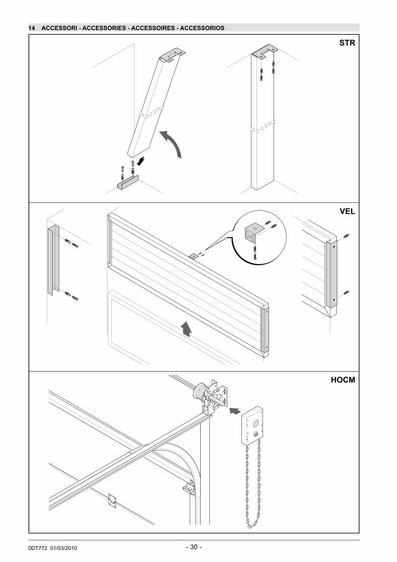
14 ACCESSORI - ACCESSORIES - ACCESSOIRES - ACCESSORIOS
STR
VEL
HOCM

- 31 - 0DT772 01/03/2010
14 ACCESSORI - ACCESSORIES - ACCESSOIRES - ACCESSORIOS
LOX 1
TAMP
100
2
2
2
2
1 1

- 32 -0DT772 01/03/2010
14 ACCESSORI - ACCESSORIES - ACCESSOIRES - ACCESSORIOS
LOX SB
GLOBE SB

- 33 - 0DT772 01/03/2010

- 34 -0DT772 01/03/2010
IT
EN
ES
FR
Fabbricante: DITEC S.p.A.Indirizzo: via Mons. Banfi , 3 - 21042 Caronno P.lla (VA) - ItalyDichiara che il prodotto: LISBON è conforme ai requisiti essenziali delle seguenti direttive CE:- Direttiva compatibilità elettromagnetica 89/336/EEC- Direttiva macchine 98/37/EC- Direttiva prodotti da costruzione 89/106/EECè conforme alle seguenti caratteristiche della norma EN 13241-1 (Allegato ZA):- Controllo della produzione in fabbrica (Conforme)- Rilascio di sostanze pericolose (Conforme)
- Resistenza al carico del vento (Classe 2)- Apertura sicura (Conforme)- Defi nizione della geometria delle parti in vetro (Conforme)- Resistenza meccanica e stabilità (Conforme)- Forze di manovra (Conforme)Organismo notifi cato: C.S.I. S.p.A.Registrazione numero: CPD/0497/047/05 - CPD/0497/065/05 - CPD/0497/048/05.Indirizzo: Viale Lombardia, 20 - 20021 Bollate (MI) - ITALY
Caronno Pertusella, 11/12/2009 Armando Vecchi
(Managing Director)
Constructeur : DITEC S.p.A.Adresse: via Mons. Banfi , 3 - 21042 Caronno P.lla (VA) - ItalyDéclare que le produit: LISBON est conforme aux prescriptions des directives CE suivantes:- Directive sur la compatibilité électromagnétique 89/336/EEC- Directive Machines 98/37/EC- Directive Produits de construction 89/106/EECest conforme aux caractéristiques suivantes de la normeEN 13241-1 (Annexe ZA) :- Contrôle de la production en usine (Conforme)- Rejet de substances dangereuses (Conforme)
- Résistance à la charge du vent (Classe 2)- Ouverture sécurisée (Conforme)- Défi nition de la géométrie des parties vitrées (Conforme)- Résistance mécanique et stabilité (Conforme)- Forces de manoeuvre (Conforme)Organisme agréé: C.S.I. S.p.A.n° d’enregistrement: CPD/0497/047/05 - CPD/0497/065/05 - CPD/0497/048/05.Adresse: Viale Lombardia, 20 - 20021 Bollate (MI) - ITALY
Caronno Pertusella, 11/12/2009 Armando Vecchi
(Managing Director)
Manufacturer: DITEC S.p.A.Address: via Mons. Banfi , 3 - 21042 Caronno P.lla (VA) - Italydeclares that the product: LISBON complies with the essential requirements of the following EC directives:- EMC Directive 89/336/EEC- Machinery Directive 98/37/EC- Construction Products Directive 89/106/EECcomplies with the following characteristics of EN 13241-1 standard (Annex ZA):- Factory production control (Pass)- Release of dangerous substances (Pass)
- Resistance to wind load (Class 2 )- Safe opening (Pass)- Defi nition of geometry of glass components (Pass)- Mechanical resistance and stability (Pass)- Operating forces (Pass)Approved body: C.S.I. S.p.A.Registration number: CPD/0497/047/05 - CPD/0497/065/05 - CPD/0497/048/05.Address: Viale Lombardia, 20 - 20021 Bollate (MI) - ITALY
Caronno Pertusella, 11/12/2009 Armando Vecchi
(Managing Director)
Fabricante: DITEC S.p.A.Dirección:via Mons. Banfi , 3 - 21042 Caronno P.lla (VA) - ItalyDeclara que el producto: LISBON es conforme a los requisitos esenciales de las siguientes disposiciones CE:- Disposición compatibilidad electromagnética 89/336/EEC- Disposición máquinas 98/37/EC- Disposición productos de construcción 89/106/EECes conforme a las siguientes características de la normaEN 13241-1 (Anexo ZA):- Control de la producción en fábrica (Conforme)- Liberación de sustancias peligrosas (Conforme)
- Resistencia a la carga del viento (Clase 2)- Apertura segura (Conforme)- Defi nición de la geometría de las partes en vidrio (Conforme)- Resistencia mecánica y estabilidad (Conforme)- Fuerzas de maniobra (Conforme)Organismo notifi cado: C.S.I. S.p.A.Registro número: CPD/0497/047/05 - CPD/0497/065/05- CPD/0497/048/05.Dirección: Viale Lombardia, 20 - 20021 Bollate (MI) - ITALY
Caronno Pertusella, 11/12/2009 Armando Vecchi
(Managing Director)
DICHIARAZIONE DI CONFORMITÀ CE
EC DECLARATION OF CONFORMITY
DECLARATION DE CONFORMITE CE
DECLARACIÓN DE CONFORMIDAD CE

- 35 - 0DT772 01/03/2010
ISTRUZIONI D’USO E MANUTENZIONE
DISPOSITIVI DI AZIONAMENTO MANUALE L’azionamento manuale deve essere eseguito solo tramite dispositivi atti allo scopo. Nel caso di porte motorizzate utilizzare: DODSBC - Azionamento a catena o SBV/SBO - dispositivo ad asta. Nel caso di porte manuali l’azionamento deve essere realizzato mediante apposito paranco a catena HOCM, calettato all’albero torsionale. Lo sbloccaggio del motoriduttore deve essere utilizzato solo in fase di manutenzione da personale addestrato. VERSIONE MOTORIZZATA (DOD14PS)Il comando della versione motorizzata è a “uomo presente”: tenere azionato il selettore nel senso di apertura o chiusura per ottenere il movimento.VERSIONE AUTOMATICARiferirsi ai manuali d’uso dei quadri elettronici impiegati nelle relative automazioni.
AVVERTENZE GENERALI PER LA SICUREZZALe presenti avvertenze sono parte integrante ed essenziale del prodotto e devono essere consegnate all’utilizzatore. Forniscono importanti indicazioni riguardanti la sicurezza di installazione, uso e manutenzione. È necessario conservare queste istruzioni e trasmetterle ad eventuali subentranti nell’uso dell’impianto.Questo prodotto dovrà essere destinato solo all’uso per il quale è stato espressamente concepito.Ogni altro uso è da considerarsi improprio e quindi pericoloso. Il costruttore non può essere considerato responsabile per eventuali danni causati da usi impropri, erronei ed irragionevoli. Evitare di operare in prossimità delle cerniere o organi meccanici in movimento. Non entrare nel raggio di azione della porta mentre è in movimento. Non opporsi al moto della porta poiché può causare situazioni di pericolo. Non permettere ai bambini di giocare o sostare nel raggio di azione della porta. Tenere fuori dalla portata dei bambini i radiocomandi e/o qualsiasi altro dispositivo di comando, per evitare che la porta motorizzata possa essere azionata involontariamente. In caso di guasto o di cattivo funzionamento del prodotto, disinserire l’interruttore di alimentazione, astenendosi da qualsiasi tentativo di riparazione o di intervento diretto e rivolgersi solo a personale professionalmente competente. Il mancato rispetto di quanto sopra può creare situazioni di pericolo.Qualsiasi intervento di pulizia, manutenzione o riparazione, deve essere effettuato da personale professionalmente competente. Per garantire l’efficienza dell’impianto ed il suo corretto funzionamento è indispensabile attenersi alle indicazioni del costruttore facendo effettuare da personale professionalmente competente la manutenzione periodica della porta o cancello motorizzati. In particolare si raccomanda la verifica periodica del corretto funzionamento di tutti i dispositivi di sicurezza. Gli interventi di installazione, manutenzione e riparazione devono essere documentati e tenuti a disposizione dell’utilizzatore. open
close
openor
close
closeor
open
MANUTENZIONELa manutenzione della porta deve essere eseguita da personale tecnico specializzato.Piano di manutenzione (ogni 6 mesi):• La manutenzione e la lubrifi cazione di parti meccaniche si devono eseguire a porta abbassata
e nel caso di funzionamento automatico con l’alimentazione degli organi elettrici assente.• Verifi care il funzionamento dei dispositivi di sicurezza (nelle versioni manuali il dispositivo
di rottura dei cavi e delle molle. Nelle versioni automatiche la motorizzazione).• Verifi care l’usura delle funi di sollevamento.• Verifi care il libero scorrimento dei cavi nei tamburi.• Con olio al silicone, lubrifi care periodicamente le cerniere i cuscinetti i perni delle ruote e le
molle di torsione.• Controllare che non ci siano ostacoli che alterino il corretto scorrimento delle ruote nelle guide.• Verifi care che la struttura superiore di scorrimento sia perfettamente ancorata al solaio
soprastante e che quindi non siano presenti difetti, pieghe,o cedimenti.• Controllare che non vi siano viti o bulloni allentati.• Non modifi care nessuna parte del sistema di sollevamento e/o scorrimento.• Utilizzare sempre ricambi originali DITEC. In caso contrario si declina ogni responsabilità
per eventuali danni a persone o cose.Questo tipo di manutenzione deve essere eseguita periodicamente sulle porte, si consiglia pertanto di tenere aggiornato un libro di manutenzione indicando su di esso la matricola della porta indicata nella targhetta di riconoscimento.Operazioni da NON effettuarsi mai durante la manutenzione:• Non tagliare una o più funi di trazione del portone• Non allentare la tensione delle molle (tale tensione è calcolata dal costruttore del portone
in base al peso del manto).• Non manomettere i dispositivi di sicurezza• Non allentare i bulloni di fi ssaggio delle cerniere esistenti tra i pannelli.
DODSBC
DODSBV
DOD14PSDA
STA
CC
AR
E E
CO
NS
EG
NA
RE
ALL
’UTI
LIZZ
ATO
RE
DITEC S.p.A.Via Mons. Banfi , 321042 Caronno Pertusella (VA) - ITALYTel. +39 02 963911 - Fax +39 02 9650314www.ditec.it - [email protected]
IT
Installatore:

- 36 -0DT772 01/03/2010
USE INSTRUCTIONS
MAINTENANCEThe maintenance of the door must be carried out by specialist technicians.Maintenance schedule (every 6 months):• The maintenance and lubrication of the mechanical parts must be performed with the door
lowered and, in the case of automatic functioning, with the power switched off.• Check the functioning of the safety devices (the cable and spring breakage device in the
manual versions and the motor in the automatic versions).• Check the raising cables for signs of wear.• Check that the cables slide freely in the cylinders.• Periodically lubricate the hinges, bearings, wheel pivots and torsion springs.• Check that there are no obstacles that alter the correct sliding of the wheels in the
tracks.• Check that the upper sliding structure is perf ectly anchored to the ceiling and that there
are no faults, folds or sagging.• Check that there are no loose screws or bolts.• Do not modify any part of the raising and/or sliding system.• Always use original DITEC spare parts. No responsibility can be accepted for any damage
to people or property if original DITEC spare parts are not used.This type of maintenance must be performed periodically on the doors. It is therefore advisable to keep an up-to-date maintenance book that indicates the registration number of the door as shown on its identity plaque.Operations that must NEVER be carried out during maintenance:• Do not cut one or more of the traction cables of the door • Do not loosen the tension of the springs (this tension has been calculated by the
manufacturer on the basis of the weight of the curtain).• Do not tamper with the safety devices • Do not loosen the anchorage bolts of the hinges situated between the panels.
MANUAL OPERATION DEVICE Manual operation must only be carried out using the devices designated for this purpose. For motorised doors use: DODSBC - Chain drive or SBV/SBO - rod device. Manual doors must be operated by means of an appropriate HOCM chain block, splined to the torsion shaft. The gearmotor release should only be used during the maintenance phase by skilled personnel. MOTORISED VERSION (DOD14PS)The motorised version is controlled with a “person present”: keep the selector in the opening or closing position to obtain movement.AUTOMATIC VERSIONRefer to the use manuals relative to the electronic panels used in the relative automations.
GENERAL SAFETY PRECAUTIONSThe following precautions are an integral and essential part of the product and must be supplied to the user. Read them carefully as they contain important indications for the safe installation, use and maintenace. These instruction must be kept and forwarded to all possible future user of the system. This product must be used only for that which it has been expressely designed. Any other use is to be considered improper and therefore dangerous.The manufacturer cannot be held responsible for possible damage caused by improper, erroneous or unresonable use. Avoid operating in the proximity of the hinges or moving mechanical parts. Do not enter the fi eld of action of the motorised door or gate while in motion. Do not obstruct the motion of the motorised door or gate as this may cause a situation of danger. Do not lean against or hang on to the barrier when it is moving. Do not allow children to play or stay within the fi eld of action of the motorised door or gate. Keep remote control or any other control devices out of the reach of children, in order to avoid possible involuntary activation of the motorised door or gate. In case of breack down or malfunctioning of the product, disconnect from mains, do not attempt to repair or intervene directly and contact only qualifi ed personnel. Failure to comply with the above may create a situation of danger. All cleaning, maintenance or repair work must be carried out by qualifi ed personnel.In order to guarantee that the system works effi ciently and correctly it is indispensable to comply with the manufacturer’s indications thus having the periodic maintenance of the motorised door or gate carried out by qualifi ed personnel.In particular regular checks are recommended in order to verify that the safety devices are operating correctly. All installation, maintenance and repair work must be documented and made available to the user.
open
close
openor
close
closeor
open
DODSBC
DODSBV
DOD14PS DE
TAC
H A
ND
DE
LIV
ER
TO
TH
E C
US
TOM
ER
DITEC S.p.A.Via Mons. Banfi , 321042 Caronno Pertusella (VA) - ITALYTel. +39 02 963911 - Fax +39 02 9650314www.ditec.it - [email protected]
Installatore:
EN
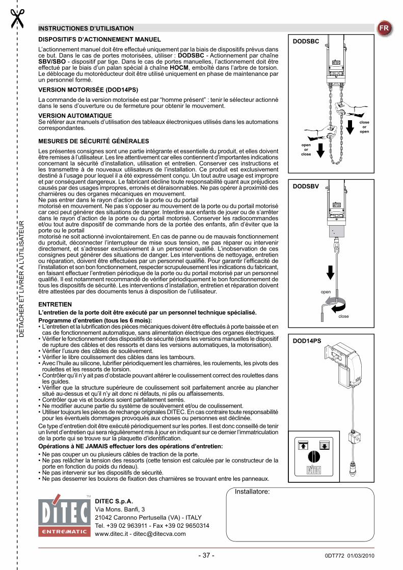
- 37 - 0DT772 01/03/2010
INSTRUCTIONES D’UTILISATION
ENTRETIENL’entretien de la porte doit être exécuté par un personnel technique spécialisé. Programme d’entretien (tous les 6 mois):• L’entretien et la lubrifi cation des pièces mécaniques doivent être effectués à porte baissée et en
cas de fonctionnement automatique, sans alimentation électrique des organes électriques. • Vérifi er le fonctionnement des dispositifs de sécurité (dans les versions manuelles le dispositif
de rupture des câbles et des ressorts et dans les versions automatiques, la motorisation). • Vérifi er l’usure des câbles de soulèvement. • Vérifi er le libre coulissement des câbles dans les tambours. • Avec l’huile au silicone, lubrifi er périodiquement les charnières, les roulements, les pivots des
roulettes et les ressorts de torsion. • Contrôler qu’il n’y ait pas d’obstacle pouvant altérer le coulissement correct des roulettes dans
les guides. • Vérifi er que la structure supérieure de coulissement soit parfaitement ancrée au plancher
situé au-dessus et qu’il n’y ait donc ni défauts, ni plis ou affaissements. • Contrôler que vis et boulons soient parfaitement serrés. • Ne modifi er aucune partie du système de soulèvement et/ou de coulissement. • Utiliser toujours les pièces de rechange originales DITEC. En cas contraire toute responsabilité
pour les éventuels dommages provoqués aux choses ou personnes est déclinée. Ce type d’entretien doit être exécuté périodiquement sur les portes. Il est donc conseillé de tenir un livret d’entretien qui sera régulièrement mis à jour en indiquant sur ce dernier l’immatriculation de la porte qui se trouve sur la plaquette d’identifi cation. Opérations à NE JAMAIS effectuer lors des opérations d’entretien:• Ne pas couper un ou plusieurs câbles de traction de la porte.• Ne pas relâcher la tension des ressorts (cette tension est calculée par le constructeur de la
porte en fonction du poids du rideau).• Ne pas intervenir sur les dispositifs de sécurité. • Ne pas desserrer les boulons de fi xation des charnières se trouvant entre les panneaux.
DISPOSITIFS D’ACTIONNEMENT MANUELL’actionnement manuel doit être effectué uniquement par la biais de dispositifs prévus dans ce but. Dans le cas de portes motorisées, utiliser : DODSBC - Actionnement par chaîne SBV/SBO - dispositif par tige. Dans le cas de portes manuelles, l’actionnement doit être effectué par le biais d’un palan spécial à chaîne HOCM, emboîté dans l’arbre de torsion. Le déblocage du motoréducteur doit être utilisé uniquement en phase de maintenance par un personnel formé. VERSION MOTORISÉE (DOD14PS)La commande de la version motorisée est par “homme présent” : tenir le sélecteur actionné dans le sens d’ouverture ou de fermeture pour obtenir le mouvement. VERSION AUTOMATIQUESe référer aux manuels d’utilisation des tableaux électroniques utilisés dans les automations correspondantes.
MESURES DE SÉCURITÉ GÉNÉRALESLes présentes consignes sont une partie intégrante et essentielle du produit, et elles doivent être remises à l’utilisateur. Les lire attentivement car elles contiennent d’importantes indications concernant la sécurité d’installation, utilisation et entretien. Conserver ces instructions et les transmettre à de nouveaux utilisateurs de l’installation. Ce produit est exclusivement destiné à l’usage pour lequel il a été expressément conçu. Un tout autre usage est impropre et par conséquent dangereux. Le fabricant décline toute responsabilité quant aux préjudices causés par des usages impropres, erronés et déraisonnables. Ne pas opérer à proximité des charnières ou des organes mécaniques en mouvement.Ne pas entrer dans le rayon d’action de la porte ou du portailmotorisé en mouvement. Ne pas s’opposer au mouvement de la porte ou du portail motorisé car ceci peut générer des situations de danger. Interdire aux enfants de jouer ou de s’arrêter dans le rayon d’action de la porte ou du portail motorisé. Conserver les radiocommandes et/ou tout autre dispositif de commande hors de la portée des enfants, afi n d’éviter que la porte ou le portailmotorisé ne soit actionné involontairement. En cas de panne ou de mauvais fonctionnement du produit, déconnecter l’interrupteur de mise sous tension, ne pas réparer ou intervenir directement, et s’adresser exclusivement à un personnel qualifi é. L’inobservation de ces consignes peut générer des situations de danger. Les interventions de nettoyage, entretien ou réparation, doivent être effectuées par un personnel qualifi é. Pour garantir l’effi cacité de l’installation et son bon fonctionnement, respecter scrupuleusement les indications du fabricant, en faisant effectuer l’entretien périodique de la porte ou du portail motorisé par un personnel qualifi é. Il est notamment recommandé de vérifi er périodiquement le bon fonctionnement de tous les dispositifs de sécurité. Les interventions d’installation, entretien et réparation doivent être attestées par des documents tenus à disposition de l’utilisateur. open
close
openor
close
closeor
open
DODSBC
DODSBV
DOD14PS
DE
TAC
HE
R E
T LI
VR
ER
A L
’UTI
LIS
ATE
UR
DITEC S.p.A.Via Mons. Banfi , 321042 Caronno Pertusella (VA) - ITALYTel. +39 02 963911 - Fax +39 02 9650314www.ditec.it - [email protected]
Installatore:
FR

- 38 -0DT772 01/03/2010
ISTRUCCIONES DE USO
MANTENIMIENTO El mantenimiento de la puerta tiene que ser realizado por personal técnico especializado.Plan de mantenimiento (cada 6 meses):• El mantenimiento y el lubricado de partes mecánicas se tienen que efectuar con la puerta
bajada y en caso de funcionamiento automático con la alimentación de los órganos eléctricos desconectada.
• Verifi car el funcionamiento de los dispositivos de seguridad (en las versiones manuales el dispositivo de rotura de los cables y de los resortes. En las versiones automáticas la motorización).
• Verifi car el desgaste de los cables de elevación.• Verifi car el libre deslizamiento de los cables en los tambores.• Con aceite de silicona, lubricar periódicamente las bisagras, los cojinetes, los pernos de
las ruedas y los resortes de torsión.• Controlar que no hayan obstáculos que alteren el correcto deslizamiento de las ruedas
en las guías.• Verifi car que la estructura superior de deslizamiento esté perfectamente anclada al piso
de arriba y que por lo tanto no estén presentes defectos, pliegues, o afl ojamientos.• Controlar que no hayan tornillos o pernos afl ojados.• No modifi car ninguna parte del sistema de elevación y/o deslizamiento.• Utilizar siempre recambios originales DITEC. De lo contrario se declina toda responsabilidad
por eventuales daños a personas o cosas.Este tipo de mantenimiento se tiene que efectuar periódicamente en las puertas, por lo tanto se aconseja mantener al día un libro de mantenimiento indicando en éste la matrícula de la puerta indicada en la placa de reconocimiento.Operaciones que NO hay que efectuar nunca en las operaciones de mantenimiento:• No cortar uno o más cables de tracción de la puerta. • No afl ojar la tensión de los resortes (dicha tensión está calculada por el constructor de la puerta
en base al peso de la placa).• No modifi car los dispositivos de seguridad• No afl ojar los pernos de fi jación de las bisagras existentes entre los paneles.
DISPOSITIVOS DE ACCIONAMIENTO MANUALEl accionamiento manual ha de realizarse solo a través de dispositivos adecuados a la fi nalidad. En el caso de puertas motorizadas utilizar: DODSBC - Accionamiento de cadena o SBV/SBO - dispositivo de barra. En caso de puertas manuales el accionamiento ha de realizarse mediante aparejo de cadena HOCM, colocado en el eje torsional. El desbloqueo del motorreductor ha de utilizarse solo en fase de mantenimiento por personal formado. VERSIÓN MOTORIZADA (DOD14PS)El mando de la versión motorizada es de “hombre presente”: mantener accionado el selector en el sentido de apertura o cierre para obtener el movimiento.VERSIÓN AUTOMÁTICAHacer referencia a los manuales de uso de los cuadros electrónicos empleados en los relativos automatismos.
ADVERTENCIAS GENERALES DE SEGURIDADLas siguientes advertencias forman parte integrante y esencial del producto y deben ser entregadas al usuario. Léanse atentamente porque contienen importantes indicaciones sobre la seguridad durante la instalaciòn, el uso y el mantenimiento. Conservar estas instrucciones y entregarlas a futuros usuarios. Este producto debe ser destinado ùnicamente al uso para el que ha sido concebido. Cualquier otro tipo de utilizaciòn debe sonsiderarse improprio y por lo tanto peligroso. El costructor no puede considerarse responsable por daños provocados por el uso erròneo, improprio o no razonable del producto. Evitar operaciones cerca de las bisagras o elementos mecànicos enmovimiento.No entrar en el radio de acciòn de la puerta o verja motorizada durante su movimiento. No oporse al movimiento de la puerta motorizada: puede ser peligroso! No permitir que los niños jueguen o permanezcan en el radio de acciòn de la puerta motorizada. Conservar fuera del alcance de los niños el telemando y/o cualquier otro dispositivo de mando, para evitar el accionamiento accidental. En caso de aver’a o mal funcionamiento, desconectar el interruptor de alimentaciòn, evitar tentativas de reparaciòn o intervenciones directas, y llmar solamente a personal profesional competente. No respectar estas reglas puede crear situaciones de peligro. La limpieza, el mantenimiento y las reparaciones deben ser efectuadas por personal profesional competente. Para garantizar la efi ciencia y el correcto funcionamiento de la instalaciòn es indispensables atenerse a las indicaciones del costructor, encargando a personal profesional competente el mantenimiento periodico de la puerta o verja motorizada. Se recomienda en particular comprobar periòdicamente el buen funcionamiento de los dispositivos de seguridad. Los operaciones de instalaciòn, mantenimiento y reparaciòn deben ser documentadas, y los comprobantes deben estar a disposiciòn del usuario.
ES
QU
ITA
R Y
EN
TRE
GA
R A
L U
SU
AR
IO
DITEC S.p.A.Via Mons. Banfi , 321042 Caronno Pertusella (VA) - ITALYTel. +39 02 963911 - Fax +39 02 9650314www.ditec.it - [email protected]
Installatore:
open
close
openor
close
closeor
open
DODSBC
DODSBV
DOD14PS

IT
EN
FR
Tutti i diritti sono riservatiI dati riportati sono stati redatti e controllati con la massima cura. Tuttavia non possiamo assumerci alcuna responsabilità per eventuali errori, omissioni o approssimazioni dovute ad esigenze tecniche o grafi che.
All right reservedAll data and specifi cations have been drawn up and checked with the greatest care. The manufacturer cannot however take any responsibility for eventual errors, ommisions or incomplete data due to technical or illustrative purposes.
Touts droits reservésLes informations mentionnées dans ce catalogue ont été controlées avec la plus grande attention. Toutefois, nous déclinos toute responsabilité en cas d’erreurs, omissions ou approximations dépendant d’exigences techniques ou graphiques.
ESTodos los derechos son reservadosLos datos que se indican han sido redactados y controlados con la màxima atenciòn. Sin embargo no podemos asumir ninguna responsabilidad por eventuales errores, omisiones o aproximaciones debidas a exigencias técnicas o gràfi cas.

DITEC S.p.A. Via Mons. Banfi, 3 21042 Caronno P.lla (VA) Italy Tel. +39 02 963911 Fax +39 02 9650314www.ditec.it [email protected]
DITEC BELGIUM LOKEREN Tel. +32 9 3560051 Fax +32 9 3560052 www.ditecbelgium.be DITEC DEUTSCHLAND OBERURSELTel. +49 6171 914150 Fax +49 6171 9141555 www.ditec-germany.de DITEC ESPAÑA S.L.U. ARENYS DE MAR Tel. +34 937958399Fax +34 937959026 www.ditecespana.com DITEC FRANCE MASSY Tel. +33 1 64532860 Fax +33 1 64532861 www.ditecfrance.comDITEC GOLD PORTA ERMESINDE-PORTUGAL Tel. +351 22 9773520 Fax +351 22 9773528/38 www.goldporta.com DITEC SVIZZERABALERNA Tel. +41 848 558855 Fax +41 91 6466127 www.ditecswiss.ch DITEC ENTREMATIC NORDIC LANDSKRONA-SWEDENTel. +46 418 514 50 Fax +46 418 511 63 www.ditecentrematicnordic.com DITEC TURCHIA ISTANBUL Tel. +90 21 28757850Fax +90 21 28757798 www.ditec.com.tr DITEC AMERICA ORLANDO-FLORIDA-USA Tel. +1 407 8880699 Fax +1 407 8882237www.ditecamerica.com DITEC CHINA SHANGHAI Tel. +86 21 62363861/2 Fax +86 21 62363863 www.ditec.cn