portable exhaust gas analyzer operators manual - emsgas · portable exhaust gas analyzer operators...
TRANSCRIPT

Portable Exhaust Gas AnalyzerOperators Manual
Model # 5003 (4 & 5 Gas) Live Reading only and Model # 8000 (Wireless)
Emissions Systems, Inc.480 Wright Dr.
Lake In The Hills, IL. 60156Voice & Fax: 1-847-669-8044Website: www.emsgas.com
Email Address: [email protected]

2
Table of Contents
1. Technical Data ......................................................................... Page 32. General Information.................................................................. Page 43. Button Operation Model 5002.................................................. Page 54. Rear Panel Description............................................................ Page 65. Gas Analyzer Preparation........................................................ Page 76. Gas Analyzer Operation........................................................... Page 8-107. Calibration................................................................................. Page 11-138. Error Messages..................................................................... Page 149. Fuel Selection..................................................................... Page 14-1510. 4-5 Gas Selection..................................................................... Page 1611. Serial # & PEF Screen.............................................................. Page 1612. Leak Check Screen................................................................. Page 1713. Features Screen Wireless LAN Connection......................... Page 1814. Features Screen Ethernet Connection ......................... Page 1915. Contacts .................................................................................... Page 2015. Maintenance............................................................................. Page 21-2816. Diagnostic Accessories & Diagnostics...................................... Page 28-2917. Warranty.................................................................................... Page 30

3
Technical DataPower: 10 -16 VDCRanges: HC: 0 - 2000 ppm (0-20,000 ppm High Range)
CO: 0 - 10%CO2: 0 - 20%O2: 0 - 25%NO: 0 - 5000 ppm ( Nitric Oxide ) *
· Warm up: Less than 5 minutes· Display resolution: HC: 1 ppm vol.
CO: 0.01% vol.CO2: 0.1% vol.O2: 0.01% vol.NO: 1ppm*
· HD Touch Screen display: 7 “
· Accuracy ( Bar 97 EPA ASM ) HC: 4 ppm HCCO: 0.06% COCO2: 0.3% CO2O2: 0.1% O2NO: 25 ppm*
· Drift: Zero and span drift are less than ± 0.6% of full scale for the first hourand less than ± 0.4% of full scale per hour thereafter.
· System response time: Bench: 1.5 Sec/25 ft. hose 5 sec. to 90% of finalreading
· Ambient conditions: 35F (2C) to 120F (45C), rel. humidity 0-98%· Sample hose:25 feet ( 7.5 m) with QD coupling /200 F Degrees Max.· Sample probe: Stainless steel 1200 Degrees F ( replaceable flex tip )
Mass: Approx.: 10 LBS. ( 4.5 Kg )

4
General InformationCongratulations on your purchase of an EMS Exhaust Gas Analyzer. This product is
designed to assist you in the process of diagnosing driveability issues. With proper care andmaintenance this product will provide accurate information for many years to come.
IMPORTANT NOTE: Moisture is the biggest concern for prolonged good operation of the gasanalyzer. Always allow the analyzer to dry out by running the unit with ambient air. This may take onlyone auto shut down cycle or as much as a couple hours! The analyzer will not be harmed by powering upand letting it sit in standby mode till ready to use. Running the analyzer with ambient air in-betweensampling and after a day of testing, is the best thing to do for prolonged life of the bench and compo-nents not allowing carbon build up due to moisture!
Figure 1 highlights the features and buttons available on the Model 5003 front displayarea. The HC will display up to five digits and is in ppm, CO is in percentage, CO2 is in percent-age, NOX is in ppm, O2 is in percentage, LAMBDA and AFR. The buttons will be describedlater in this manual.
Figure 1
ZEROINGBUTTON
HOMEBUTTON
CONTACTBUTTON
HELPBUTTON
MENUBUTTON FUEL & 4
OR 5 GASSETTINGWINDOW
15 min.SHUTDOWNBUTTON

5
Button Operation Model 5003
Figure 2 shows the control buttons on the touch screen of the gas analyzer:1. The “Zero” button has two functions.
a. Zeroing the gas analyzer as needed during use.b. Restarting the pump following automatic shutdown.
2. The “Home” button has one function.a. Brings you back to Gas Sample screen
3. The “Menu” button has several functions.a. Access calibration screenb. Change Fuel Typec. Check bench SN and PEF Valued. Access Status for ERROR message screene. Change display to 4 or 5 Gasf. Leak Check for sample systemg. Features on LAN Conn. and Ehternet conn.
4. The “Help” button is used to access the operations manual for touch screen opera-tion, maintenance info.5. The “Contact” button is for all the EMS shipping info, phone and website.6. The “Setting Window” is for viewing what fuel type is picked (default is gasoline) andfor 4 or 5 gas setting for reading NOX.7. The “15 Min Shutdown” is for end of the day shutdown, once the button is de-pressed the pumps will run for 15 min. and shutdown. The analyzer can be powereddown now.
Figure 21
2 3 4 56
7

6
Rear Panel Description
Figure 3 shows the view from the back of the analyzer. The specific details of eachitem are described below, starting from the upper left corner of the analyzer and workingclockwise.Sample Hose Connection: The sample hose connection uses a quick disconnect cou-pler. This is helpful for storage of the analyzer and maintenance of the sample hose. Theinlet is connected to a Oil/Water separator for pre-moisture extraction.Display Control Switch: The display switch has two basic positions, Computer andDisplay. The switch should normally be in the DOWN position “Display”. If you are usingPC software for display or recording, the switch should be in the UP position. Note: Theswitch direction is based apon you looking at the display. The switch should bechanged only with power turned off.DB9 Computer Connection: This is used to connect the analyzer to your PC/laptop orwireless antenna.Power Cord: Connect to the appropriate voltage supply source.Sample Air Exhaust: The analyzer discharges the sample air out these ports. Do notplug..Drain Hose: This hose will drain moisture collected during the sample process.External Filter, Water Trap, Water/Oil Separator: This is the primary filtration system.Filter maintenance will be discussed in the Maintenance section of this manual.Water Separator Drain: Drain daily opening a ball valve.
Figure 3
WATER SEPARATORPRE-FILTER
MANUAL DRAIN
WATER TRAP PRE-FILTER W/ AUTOMATIC
DRAIN
HIGH PERFORMANCEWATER/OIL SEPARATOR
WITH MANUAL DRAIN
SAMPLEHOSE CONN.
COMPUTERMODE SWITCH
DB9COMPUTERCONN.
POWERCORD
SAMPLE AIR EXHAUST
DRAINHOSE
EXTERNALFILTER

7
Gas Analyzer PreparationGetting started is simple. Figure 4 shows the items you should have received in the
shipping container. Note: This description applies to the Model 5003 analyzer with a livereading only display. The first step is assembling the sample hose. Once the sample hose,handle and S.S. probe are assembled, connect the hose to the sample hose QD fitting on the
inlet connection of the water/oil separator.
Figure 4
The next step is providing power to the analyzer. The analyzer should be connected to a12v DC power source. You have several options:
1. Cigarette Lighter Connection - Figure 5 (Supplied by EMS)2. Cigarette lighter to battery connection with adapter - Figure 6 (Optional)3. AC to DC Power Supply - Figure 7 ( 6 AMP min.) (Optional)
Figure 5 Figure 6 Figure 7
NOTE: Power supply voltage to the analyzer needs to be a consistent 12 VDC. If anystart up issues occur check power supply or battery.

8
Gas Analyzer OperationShortly after applying power, the analyzer will display the EMS logo & world start up
screen. It will disappear once and reappear (Figure 8) for approx.15 sec. then switch to theHome sampling screen (Figure 9). This starts the analyzer warm-up mode and will continue forapproximately 5 to 10 minutes, depending on ambient temperature. Once the warm-up is com-plete, the analyzer will go into the “ZEROING” mode to set all the gases to zero. Then the gassample mode will display all the gas values (Figure 10). 4 Gas units will show CO2, CO, HC,O2 (figure 11) Note: Below the gas data is a status line where operations and/or errors
will be displayed.
Figure 8 Figure 9
Figure 10
Once the analyzer has completed the warm-up, the sample hose can now be connectedand the probe placed in the tailpipe.
Caution: Exhaust gases pass through the gas analyzer and vent through its ex-haust. Use the analyzer in a well vented area. EMS can supply a venting hose assembly.
Note: Gas analyzers are designed for diagnostics and verification of repairs. Thesample probe should be removed from the tailpipe after taking readings to prolong
analyzer life and save on maintenance costs.The pump will continue to operate as long as the CO2 level is above 3%. The pump will
automatically shut-off after the CO2 level has been below 3% for approximately 15 minutes.The pump can be turned back on by depressing the “ZERO” button.
Caution: Monitor the clear hose between the filter assembly and the housing. Ifmoisture appears in the tubing, remove the probe from the tailpipe and disconnect thesample hose from the analyzer immediately. Use compressed air to remove moisture
from the sample hose. Operate the analzyer without the exhaust sample hose connecteduntil the moisture is removed. It may be necessary to replace the filters. Once the lines
are dry, normal operation can continue.
Figure 11

9
Gas Analyzer OperationManual Zero: Any time after warm-up, you can zero the gas readings and calibrate O2
by pressing the “ZERO” button (Figure 12). Once the button is depressed, you will see a circleshowing the button was depressed (Figure 13). When this operation is being done “ZEROING”will be displayed in the status line (Figure 14) and will flush the bench for 30 sec. with ambientair from inside the analyzer. The analyzer will shut down automatically if no CO2 is detectedafter approx. 15 min. If the pump is off, “STAND BY” will be displayed in the status line. Pushthe “ZERO” button and the pumps will automatically start. Note: The sample probe shouldbe removed from the tailpipe, when the unit is being zeroed.
Automatic Zero: The analyzer will automatically zero as needed. If the analyzer doesnot sense exhaust gases, the automatic zero procedure will begin normally after the first 15min. after start up. “ZEROING” will be displayed in the status line during this process. If exhaustgases are present, the analyzer may auto zero again.
Figure 15
Low Flow Warning: If gas flow into the bench becomes restricted due to clogged filters orrestricted sample hose, the status line will indicate “LOW FLOW” (Figure 15) and thepumps would shut off. To clear the LOW Flow waring, press the Zero button. Go to the Leakcheck screen to perform a leak test. Check the sample hose for restrictions or kinks. If noproblems are found, check the filters. Begin with the External filter and then check the Internalfilter. Keep in mind, in older models without a water trap assembly, the gas flows through theinside to the outside of the filter. The filter may look clean on the outside, but be clogged onthe inside. The best check is to look at the bottom of the external filter. If the LOW FLOWcontinues to be displayed, the solenoid valve will need to be checked or possibly replaced dueto carbon build-up.
Figure 12 Figure 13
Figure 14
10
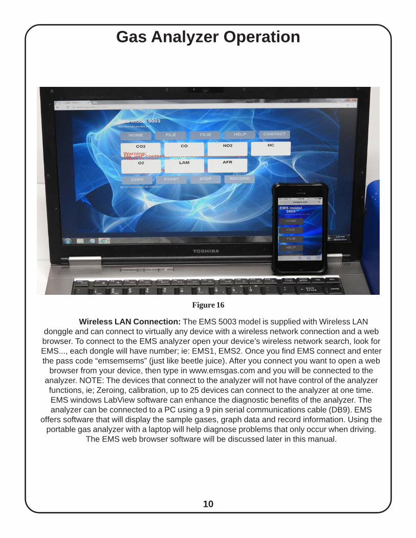
Wireless LAN Connection: The EMS 5003 model is supplied with Wireless LANdonggle and can connect to virtually any device with a wireless network connection and a webbrowser. To connect to the EMS analyzer open your device’s wireless network search, look forEMS..., each dongle will have number; ie: EMS1, EMS2. Once you find EMS connect and enterthe pass code “emsemsems” (just like beetle juice). After you connect you want to open a web
browser from your device, then type in www.emsgas.com and you will be connected to theanalyzer. NOTE: The devices that connect to the analyzer will not have control of the analyzerfunctions, ie; Zeroing, calibration, up to 25 devices can connect to the analyzer at one time.EMS windows LabView software can enhance the diagnostic benefits of the analyzer. Theanalyzer can be connected to a PC using a 9 pin serial communications cable (DB9). EMS
offers software that will display the sample gases, graph data and record information. Using theportable gas analyzer with a laptop will help diagnose problems that only occur when driving.
The EMS web browser software will be discussed later in this manual.
Gas Analyzer Operation
Figure 16

11
The gas analyzer should be checked periodically for accuracy. For normal shops usingthe analyzer this would be approx. 6-9 months, for higher usage approx. every 3 months.. Theanalyzer can be calibrated in the field. In order to perform the calibration procedure you willneed a bottle of calibration gas and a calibration kit (Figure 17). The calibration Kit can bepurchased from EMS or your local distributor. The recommended calibration gas is Bar 97 Lowand can be purchased from EMS, Part No.EMS-5502; BAR 97 LOW.
Calibration
Figure 17
Calibration Procedure:1. To begin the calibration procedure depress the “Menu” button on the Home samplingscreen. The main menu screen will show you the “Calibration” button (Figure 18) Pressthe “CAL” button and the display will go to the calibration screen and show the storedcalibration gas values highlighted in blue box (Figure 19). Compare these numbers to thecalibration gas bottle. If the numbers do not match, change the values by pressing eachgas value box, an edit screen will be displayed with a key pad. Change the values foreach gas as needed (Figure 20, 21 & 22). Once the values are changed press the “Ac-cept” button.
Figure 18 Figure 19

12
Calibration
2. The status line will display “sending cal data” (Figure 23) Once the calibration gasvalues have been sent to the bench, the analyzer will Zero for 30 seconds. Once com-pleted calibration gas can be connected and turned on. (Note: Do not adjust the regula-tor, this was preset to the appropriate flow rate.)
3. The first column shows the stored calibration values typed in from the cal bottle. Themiddle column will display the cal gas live reading values from the cal bottle, the lastvalue is a % varience to the calibration values. Once the gas values stabilize (Figure 24),press the “Save” button ( Figure 25). The screen will go blank for a second and return toverify the gas values are reading accurately. A percentage difference value is shown in the3rd column to see how far off calibration was before and then after calibration (Figure26). The calibration process is now complete. Turn the calibration gas off to save gas.The calibration process should take approx 1 1/2 min..
Figure 20 Figure 21
Figure 22 Figure 23

13
Calibration
Figure 24 Figure 25
Figure 26 Figure 27
NOTE: The hydrocarbon gas in the calibration cylinder is propane (LPG), and the gasanalyzer generally measures hexane. This is problematical, as hexane is a molecule thatis about twice as large as propane. This means that the typical HC reading on the gasanalyzer (hexane) should be about ½ the propane value (Figure 27) on the calibrationcylinder tag. That is, if the tag states that the cylinder contains 1200 ppm propane, thenan analyzer measuring HC as hexane will report HC at about 600 ppm. The PEF value( Propane equivalence factor) can be used to calculate the Hexane gas value. You haveaccess to the bench PEF value in the Menu screen, under the Serial # button. You canalso go into the fuel selction screen and pick LPG for an accurate calibration gas valuethat the display calculates automatically.

14
If the optical bench detects any errors during operation, a message will be displayed on theStatus Line of the Home screen. If any error messages comes up, press the menu button, andthen press the status button (Figure 28). At this point you can see any errors being sent fromthe optical bench (Figure 29). The errors that would possibly be displayed are:
- HC C WARN: This could be a bad calibration or bad optical bench.- CO C WARN: This could be a bad calibration or a bad optical bench.- CO2 C WARN: This could be a bad calibration or a bad optical bench.- NOX C WARN: This could be a bad calibration or a bad NOX sensor.- O2 C WARN: This would be a bad O2 sensor.-LOW Flow: This would be clogged filter or restricted sample hose.
If an error message does appear and is a bad calibration or the optical bench detected as notnormal, depress the “ZERO” button on the “Home” sampling screen to clear the error. If theerror message doesn’t go away, either the bench has an error or is bad or one of the sensors( O2, NOX) need to be replaced.
ERROR MESSAGES
Figure 28 Figure 29
FUEL SELECTIONThe default fuel is Gasoline, you can pick from the default and E85, Diesel, LPG, & CNG fuel(Figure 30). The purpose of the fuel change is to calculate the LAMBDA/AFR value more accu-rately for the different fuel types. This is done by changing the atomic ratio’s of the differentfuels in the LAMBDA formula. The formula used is the Brentscheinder Formula (Figure 31).
Figure 30

15
Figure 31
FUEL SELECTION

16
4-5 GAS SELECTIONThe Gas Analyzer will be set up for 4 or 5 gas operation at the time of purchase. The 4 gas unitonly has HC,CO,CO2, AFR and LAMBDA and the 5 gas unit has HC,CO,CO2, NOX, AFR andLAMBDA. The unit would not need to be changed by the customer. To choose 4-5 gas go to themenu screen and press 5 or 4 gas button (Figure 32), then choose the 5 or 4 gas button (Figure33). Return to the Home screen and the display will indicate 4 or 5 gas in the setting window.
Figure 32 Figure 33
Serial # SELECTIONThe Gas Analyzer has a production serial # which identifies the unit for software communicationand for the optional Ethernet subscription verification. To access the analyzer serial #, go to themenu screen and press serial # button (Figure 34). The Screen will show the analyzer SN,PEF Value, Version, and WiFi Net name. The PEF or Propane Equivalence Factor is usedduring calibration or sampling LPG fuel. The hydrocarbon gas in the calibration cylinder is pro-pane, and the gas analyzer generally measures hexane. This is problematical, as hexane is amolecule that is about twice as large as propane. This means that the typical HC reading onthe gas analyzer (hexane) should be about ½ the propane value on the calibration cylinder tag.That is, if the tag states that the cylinder contains 1200 ppm propane, then an analyzer measur-ing HC as hexane will report HC at about 600 ppm. The propane in the calibration gas cylindermay be converted to equivalent hexane by multiplying it by the Propane Equivalence Factor(PEF) for the analyzer, or by setting the analyzer in LPG fuel measurement mode, whereby ameasurement conversion for propane is initiated. EMS 5003 gas analyzers automatically readsthe PEF and converts HC in calibration, so this problem is automatically handled by EMS ana-lyzers. The other gases (CO, CO2, O2 NOx) do not have this problem, and so the readingsmay be used directly.
Figure 34

17
LEAK CHECK SELECTIONThe Gas Analyzer needs to be checked occasionally for LEAKS. O2 leaks can cause gasreadings to be off or not read at all. Leak Check should be performed after every filter changeout to insure no O2 leaks causing invalid gas readings. To perform a Leak Check press themenu button on the Home screen and press the leak check button on the Menu screen (Figure35). This brings you to the leak check screen (Figure 36) pick 30 or 60 Sec. for the duration ofthe check.Plug the inlet quick connector on the analyzer with a rubber cap for an internal leak check. Themodel 5003 will show LOW FLOW on the screen and the pumps will shut off, press the Testbutton to start the 30-60 sec. leak check. If the pumps stay off the duration of the test, thereare no leaks and the test button will change to green.·Leak Check your sample hose and probe every filter change out only after you have verified nointernal instrument leaks. Connect the sample hose to the analyzer and plug the end of theprobe with the red/black plastic cap supplied by EMS. The same low flow codes will come upas described above and the low flow should hold for the duration of the test. If a leak is de-tected, meaning the pumps turn back on losing vacuum, the most common leak is at the externalfilter connection. This can be verified by using a butane lighter opening raw butane next to thefilter head, your HC reading will spike if there is a leak. You should also check all threadedconnections and hose connections including tie straps, twisting to ensure a seal.
Figure 35 Figure 36

18
FEATURES SCREENUpdates coming to this section in the first quar-ter of 2017! Please check the website for up-dates.
The Features screen gives you explanations of how to connect to the Wireless LAN and theEthernet cable connection for Remote access subscription. To get to the features screen pressthe menu button on the Home screen and press the Features button on the Menu screen (Fig-ure 37). This brings you to the Features screen.Wireless LAN Connection: To connect to the EMS wireless dongle, open your device networkconnection screen ( Figure 38) click the EMS LAN connection, it will require a password. Thepassword is EMS 3 times: “emsemsems” (Figure 39). Once you have connected to the EMSdongle, open you web browser for connecting to the internet, type in the EMS website:www.emsgas.com and will connect directly to the analyzer. The devices will have control of theZERO function of the analyzer only. Any other device that connects can view gas readings only,connect up to 25 devices at one time. (Figure 40).
Figure 37
Figure 38 Figure 39

19
FEATURES SCREENThe Gas Analyzer Wireless Browser screen shows all five gases and Lambda/AFR. The onlyfunction button is the ZERO button.
The Gas Analyzer can also be connected to a CAT 5 Ethernet cable to connect direct to theanalyzer from a remote location. This service is a yearly subscription based feature, check withEMS for the latest pricing.
Figure 40

20
Contacts Screen
Help Screen

21
MaintenanceMaintenance of the analyzer is essential for accuracy and optimal performance. The
filters, hoses and connections should be checked on a regular basis. Maintenance of the gasanalyzer is simple and only requires a few minutes, but the time you spend will pay off withaccuracy during the diagnostic process and extended life of the equipment . Specific mainte-nance procedures are described below:
External Analyzer Maintenance:1. The exhaust sample hose should be cleaned once a week (Figure 43). Disconnect the
hose from the filter assembly and blow shop air through the hose. This will remove carbon, dirtand moisture that collects inside the hose. The exhaust probe tip should be checked for leakagearound the flex tube. Exhaust gas should only enter through the holes in the exhaust tip end. Ifthe flex tube is worn and loose, oxygen may enter around the worn flex tube. A simple way tocheck the flex tube is blowing shop air through the hose and spraying soapy water around theflex tube. If bubbles are seen the exhaust probe tip should be replaced. The sample hose andplumbing should be checked for leaks. Checking for leaks is simple, with the analyzer in samplemode, place a rubber cap over the probe tip holes. Within a few seconds the analyzer displayshould read low flow and the pumps turn off. If the analyzer does not hold vacuum, a leak ispresent in the system. Check the sample hose for leaks first, check the external filter next andfinally the internal hoses. Contact EMS or your local distributor for assistance if required.
2. The External Filter should be checked often (Figure 44). This filter catches most of theparticles and impurities. The life-cycle of this filter depends on usage, but the average shopreplacement is 3 months. To determine the correct replacement interval for your shop, checkthe filter once a month.
Filter Replacement:External filter is located on the back side angle bracket, remove the filter bowl fromthe filter head, turn clockwise to loosen and remove. Loosen the retainer holding thefilter turning clockwise. replace the filter, screw filter retainer counter-clockwise totighten. Make sure the filter goes on straight, this is the most common point forleaks! Screw on filter bowl turning counter-clockwise. Do a leak check after any filterchange.
Figure 43 Figure 44

22
MaintenanceInternal Analyzer Maintenance:The maintenance items discussed below are located inside the analyzer. The outside
cover will need to be removed to gain access. The cover is held in place with 12 screws, 5 oneach side panel and two at the top behind the handle.
3. The Internal Filter is located inside the analyzer (Figure 45). This filter is designed tocatch particles missed by the External Filter. The replacement interval varies, but a goodstarting point, is replacing the filter every other time you replace the External Filter. Note: Thisfilter is directional, check the arrow on the filter.
4. Oxygen Sensor should be replaced as required (Figure 46). Replacement intervalswill vary, but the average life-cycle is 9 to 12 months. A fault code will flash when the sensorneeds to be replaced, the analyzer cannot be used until the sensor is replaced. To avoidunexpected down time, the O2 sensor display can be monitored. If the reading drops below17.0% the O2 sensor should be replaced or with a volt meter when below 5 MV. Average O2sensor life is approx. 1 year. The oxygen sensor is located inside the analyzer.
a. Remove the analyzer cover. Note: The power should be disconnected prior tocover removal. The sensor is located at the left rear of the analyzer (Figure 46).b. Disconnect the two wire connector from the sensor. Rotate the sensor counter-clockwise.c. Install the new sensor, rotate clockwise until the o-ring seats. Reconnect thetwo wire connector. Replace the cover and power the analyzer. No additionalsteps are required.
5. NOx Sensor should be replaced as required (Figure 46). Replacement intervals willvary. A error will message will be displayed when the sensor needs to be replaced. The aver-age life of a NOX sensor is approx. 3 years.
a. Remove the analyzer cover. Note: The power should be disconnected prior tocover removal. The sensor is located at the left rear of the analyzer (Figure 46).b. Disconnect the four wire connector from the sensor. Rotate the sensor counter-clockwise.c. Install the new sensor, rotate clockwise until the o-ring seats. Re-connect thefour wire connector. Replace cover and power the analyzer. No additional stepsare required.
NOxSenso
O2Sensor
O2Sensor
Internal Filter O2 Sensor and NOx Sensor
NOxSensorO2
Sensor
Figure 45 Figure 46

23
The parts in need of consistent interval change out are the external & internal filters and theO2 sensor. The intervals, tools needed, part #’s, and other maintenance tips for instrument lifeare described below:
1) Internal Filter; part #: EMS-5093; 180 DAY (6 month min.) Interval.· TOOLS: 2 mm key style allen wrench, needle nose pliers, wire/zip tie strap
cutter .· Remove the 11 or 12 #6 button head screws with 2mm allen. Be careful not to
strip allen head when loosening & ONLY FINGER tight when tightening.· Remove the cover, int. filter located in the back right, cut off zip ties and use
needle nose pliers to remove the hose. Install new filter and attach two (2) newzip ties on each end to ensure no LEAKS. Attach cover back on the main hous-ing.
2) External Filter; part #: EMS-5371; 90 DAY (3 month min) Interval.· TOOLS: None required.· External filter is located on the back side angle bracket, remove the filter bowl from
the filter head, turn clockwise to loosen and remove.Loosen the retainer holding thefilter turning clockwise. replace the filter, screw filter retainer counter-clockwise totighten. Make sure the filter goes on straight, this is the most common point forleaks! Screw on filter bowl turning counter-clockwise. Do a leak check after anyfilter change.
3) O2 Sensor; part #: EMS-5060; 12-18 month (1- 1 1/2 + Year) Interval or ERROR code O2 WARN model 5003 display.
· TOOLS: 2 mm key style allen wrench· Remove the 11 or 12 #6 button head screws with 2mm allen. Be careful not to
strip allen head when loosening & ONLY FINGER tight when tightening.· Open O2 container, remove plastic sticker on bottom of sensor, and turn upside
down back inside the container. Allow to breath for 15-20 minutes. Remove thecover, O2 located in the back left. Unplug the three pin connector on the top ofthe sensor, loosen turning counter clockwise and remove. Install new sensor,marking install date, turning clockwise into the sensor block. Reattach the threepin connector to the sensor. Attach cover back on the main housing.
These three items must be regularly changed out per the above intervals. Otheritems not as critical or more complicated are described below and should bemaintained at the intervals indicated.
Maintenance
xsor
24
Maintenance4) NOX Sensor; part #: EMS-5065; 6 month min. re-calibration for accuracy and 2-3
Year Interval change out, or ERROR code NOX Z WARN 5003 model.· NOX Sensors should re-calibrated a min of 6 month intervals. New NOX sensors
require re-calibration as well as NOX accuracy checks.· NOX Sensor NOX C WARN model 5002 will appear if the sensor is bad.· TOOLS: 2 mm key style allen wrench· Remove the 12 #6 button head screws with 2mm allen. Be careful not to strip allen
head when loosening & ONLY FINGER tight when tightening.· Remove the cover, NOX located in the back left. Unplug the four pin connector on the
top of the sensor, loosen turning counter clockwise and remove. Install new sensor,marking install date, turning clockwise into the sensor block. Reattach the four pinconnector to the sensor. Attach cover back on the main housing.
5) Water Trap Assembly Filter; part #: EMS-5373; 3-6 month min. Interval· Water Trap Assembly filter is a disposable filter, with the sample flow from inside/out so
you will not see contamination. Carbon build up could cause a LOW Flow error. Un-screw the filter bowl turning clockwise to loosen. Unscrew the filter retainer turningclokwise, remove the sintered PEL filter. Install new filter, tighten filter retainer counter-clockwise, Screw on the filter bowl turning counter clockwise to tighten. NOTE: The airflow through this filter is from the inside/out, so to inspect the filter contamination, thesintered PEL filter must be removed.
6) General Every Day Operation/Maintenance for Instrument Life. NOTE: Not perform-ing these daily maintenance items could cause component failures that may not becovered under Warranty.
· Turn the 4 or 5 gas on in the morning in display mode and allow the instrument to warmup and go into auto shut down mode. This will keep the bench ready for use whenneeded, with out having to wait for the instrument to warm up. This will not damage theunit and help save time when your ready to use the analyzer.
· Moisture is your BIGGEST enemy for this instrument life! If any moisture build up isvisible in the analyzer clear hoses, allow the instrument to dry out by running ambient airthrough the analyzer continuously for a minimum of 30 minutes or until NO moisture ispresent in the hoses.
· Sample Hose and S.S. probe should be blown out with compressed air at the end ofthe day. Moisture will leave carbon build up inside the hose and deteriorate the hosecausing leaks. Clean sample hose once or twice a year by soaking in hot soapywater, blow out with compressed air.
· Leak Check should be performed after every filter change out to insure no O2 leakscausing invalid gas readings. Plug the inlet quick connector on the analyzer for aninternal leak check. The model 5003 will show LOW FLOW on the screen and thepumps will shut off, and if the pumps stay off 30 seconds there are no leaks.
· Leak Check your sample hose and probe every filter change out only after you haveverified no internal instrument leaks. Connect the sample hose to the analyzer and plugthe end of the probe with the red/black plastic cap supplied by EMS. The same lowflow codes will come up as described above and the low flow should hold for 30 sec-onds.

25
Maintenance
· Leak check failures would be if the 5003 model pumps turn on during the 30 sec-onds. The most common leak location is at the external filter head, this can becheck with a butane lighter to see if your HC reading increases. Make sure the filteris screwed on straight and the O-Ring is moistened. If the leak is at the internalfilter, twist the filter in the hose and make sure zip tie is tight or replace. If a leak isfound in the sample hose or probe, ORDER NEW parts. Sample Hose part #:EMS-5096-25, Handle part #: EMS-5097, S.S. Probe part #: EMS-5098.
· Two Cycle gasoline testing: Two cycle fuel is much more of a maintenance issuethan standard gasoline or diesel testing. In order to determine a good maintenanceschedule, check the filters once a week with a visual inspection. If a yellowish buildup in the external filter is present, this is oil contamination, and will possibly give youinaccurate readings due to HC residual build up. This would be seen after ZERO-ING the unit, and HC readings being displayed without taking an exhaust sample.This would indicate filter change out is required. For the pre-filter water trap sin-tered PEL filter, any yellowish or oil build up would require replacement. Make notesof how many tests have been preformed so you can get a bench mark for your filterchange out. If you are not changing out and cleaning the filters, this could result in abench failure due to oil contamination build up inside the IR bench. Also be carefulof how long you sample this exhaust. A longer test can result in contamination, soonly allow the unit to sample as long as needed. Afterwards, always allow the unitto purge out any contamination by running fresh air for as long as possible, or aminimum of 15 minutes or auto shut down in stand by mode. This is the best thingto do after sampling any engine and will prolong the analyzer component life.OIL/WATER SEPARATOR: The new High Performance Oil Water Separator,EMS-5151, has been added as our standard to remove more oil/water before theautomatic drain water trap assembly. The separator should be drained daily byopening the drain valve on the oil/water reservoir daily. The Small Body Separator,EMS-5151, has a ball valve drain. The separator will work better in colder weather,however to enhance the capability of the separator in hot humid weather, EMSrecommends to make a home made oil/water condenser by attaching a ICE bath.This can be done with a plastic cup filled with ice around the reservoir, or a spotcooler with compressed air. This simple trick will be very effective in pulling moremoisture out of the sample , very similar to the official state run facilities with DYNOtesting. Give it a try and you will see a huge difference! See pg, 26 for detail pic-tures.

26
Maintenance
Oil/Water Separator with PlasticCup Ice Bath
Small Body Oil/WaterSeparator EMS-5151
Spot Cooler with compressed air from “Exair”

27
Duel Filter Upgrade for Production Sampling
Maintenance
· Diesel Testing when Urea is used to reduce NOX (SCR) : The EMS analyzeris fully capable of diesel testing. Your HC reading will only be accurate for Hex-ane gas, so a Smoke/Opacity meter would be required to check PM. All othergases will be accurate including NOX. For diesel systems using the SCR systemthat sprays UREA in the exhaust to eliminate NOX, this chemical reaction pro-duces Ammonia. The presence of ammonia in vehicle exhaust presents someproblems for gas analyzers and sampling systems. Ammonium salts readily precipitate in the exhaust sample stream, which can contaminate FID andoptical gas bench components. To protect the AMBII bench, a special version ofthe in-line filter element, EMS-5093-CS, has been developed that will absorb theammonia before entering the analyzers. This would need to be added in thefield, or ordered as an extra accessory for any new units.

28
Spare Parts and AccessoriesPart No: DescriptionEMS-5060 Oxygen SensorEMS-5065 NOx SensorEMS-5093 Internal FilterEMS-5096 Exhaust HoseEMS-5097 Exhaust HandleEMS-5098 Exhaust ProbeEMS-5210 Power CordEMS-5500 Gas Calibration KitEMS-5020 12V Sample/Water PumpEMS-5031 12V HD Solenoid ValveEMS-5040 Optical BenchEMS-5041 Repaired Optical BenchEMS-5050 Flow SwitchEMS-5070 External Filter HeadEMS-5302 7” Display ScreenEMS-5306 12 VDC Power SupplyEMS-5072 HD Water Trap AssemblyEMS-5256 AC/DC Power Supply 5.5 AMPEMS-5257 USB to Serial Adapter 13"EMS-5258 DB9 Serial Cable 6 ft LongEMS-5259 DB9 Serial Cable 15 ft. LongEMS-5098-1/4-20 Exhaust Probe 1/4-20 Threaded EndEMS-5099 EVAP/Small Engine/Motor Cycle ProbeEMS-5150 Large Body Oil/Water SeparatorEMS-5151 Small Body Oil/Water SeparatorEMS-5093-CS In-line Absorber Filter for Diesel/UreaEMS-5370 External Filter Assy.EMS-5371 External FilterEMS-5372 Water Trap Assy.EMS-5373 Sintered PEL Filter
Maintenance

29
Diagnostic AccessoriesThe Y-Valve assembly (Fig. 48)was designed for pre-catalyticconverter testing and dual exhausttesting. With the real benefit beingable to hook up both pre & postcat sample hose & probes. Andswitch between both readings atthe analyzer, which saves youtime. Also check back pressureon the pre-cat side at the analyzerwith our in-line pressure gauge(Fig.49)
EMS also offers a pop nut insert tool kit (Fig.50) for the pre-cat probe w/ a 1/4”-20 threadedend. The kit includes the pop nut insert tool, 1/4-20 mandrel, box of 40 nuts, 50 pc’s 1/4-20x3/8” stainless steel SHCS, 25/64” drill bit The EMS EVAP probe,( small engine) (Fig. 51)is 3/16” O.D. and very flexible to help find radiator or exhaust leaks in tight spaces.
Figure 49Figure 48
Figure 50 Figure 51
Pre-CatProbe
Water trapAssembly
Post-CatProbe
Y-ValveAssembly
EVAPProbe

30
Warranty• Emission Systems products are guaranteed to be free of defects in material andworkmanship to the original purchaser, for a period of one year from the date ofpurchase. Probes and electrical leads are warranted for ninety days. The opticalbench is warranted for 18 Months.
• This warranty does not apply to products which have been:1) Altered2) Improperly installed, maintained or repaired.3) Damaged by accident, negligence or misuse.
• THIS WARRANTY EXCLUDES ALL INCIDENTAL OR CONSEQUENTIALDAMAGES
• If you suspect there is a problem with your unit, the operating manual should bereviewed first. Your particular problem may be covered in the operating instruc-tions. If the issue cannot be resolved, contact EMS or your authorized distributorfor additional information. If the unit requires repair, contact EMS to obtain a Re-turn Authorization Number. The unit should be properly packaged and shouldinclude all accessories. The unit should be returned in the shortest possible timeframe at customers cost, EMS will return the unit with the same shipping.
• In the USA and Canada call: 847-669-8044 for assistance.
• Outside USA call your authorized distributor for assistance.
Warranty Information:
• Date of Purchase: ____________
• Serial Number: ______________