portable executable and object file format specificationkd/lib/pecoff.doc · web viewmicrosoft...
TRANSCRIPT

Microsoft Portable Executable and Common Object File Format Specification
Microsoft CorporationRevision 6.0 - February 1999

Note This document is provided to aid in the development of tools and applications for Microsoft Windows NT® but is
not guaranteed to be a complete specification in all respects. Microsoft reserves the right to alter this document without
notice.
Microsoft, MS, MS-DOS, and CodeView are registered trademarks, and Windows, Windows NT, Win32, Win32s, and
Visual C++ are trademarks of Microsoft Corporation in the USA and other countries.
Alpha AXP is a trademark of Digital Equipment Corporation. Intel is a registered trademark, and Intel386 is a trademark
of Intel Corporation. MIPS is a registered trademark of MIPS Computer Systems, Inc. Unicode is a trademark of
Unicode, Incorporated. UNIX is a registered trademark of UNIX Systems Laboratories. Other product and company
names mentioned herein may be the trademarks of their respective owners.
© 1999 Microsoft Corporation. All rights reserved.

Contents1. General Concepts 42. Overview 53. File Headers 7
3.1. MS-DOS Stub (Image Only) 73.2. Signature (Image Only) 73.3. COFF File Header (Object & Image) 73.4. Optional Header (Usually Image Only) 10
4. Section Table (Section Headers) 164.1. Section Flags 174.2. Grouped Sections (Object Only) 19
5. Other Contents of the File 205.1. Section Data 205.2. COFF Relocations (Object Only) 205.3. COFF Line Numbers 285.4. COFF Symbol Table 295.5. Auxiliary Symbol Records 345.6. COFF String Table 385.7. The Attribute Certificate Table (Image Only) 385.8 Delay-Load Import Tables (Image Only) 39
6. Special Sections 416.1. The .debug Section 426.2. The .drectve Section (Object Only) 456.3. The .edata Section (Image Only) 456.4. The .idata Section 496.5. The .pdata Section 516.6. The .reloc Section (Image Only) 526.7. The .tls Section 546.8. The .rsrc Section 57
7. Archive (Library) File Format 617.1. Archive File Signature 627.2. Archive Member Headers 627.3. First Linker Member 637.4. Second Linker Member 647.5. Longnames Member 65
8. Import Library Format 658.1. Import Header 658.2. Import Type 668.3. Import Name Type 66
Appendix: Example Object File 67Appendix: Calculating Image Message Digests 72Fields Not To Include In Digests 72

1. General ConceptsThis document specifies the structure of executable (image) files and object files under the Microsoft Windows NT® operating system. These files are referred to as Portable Executable (PE) and Common Object File Format (COFF) files respectively. The name “Portable Executable” refers to the fact that the format is not architecture-specific.
Certain concepts appear repeatedly throughout the specification and are described in the following table:
Name Description
Image file Executable file: either a .EXE file or a DLL. An image file can be thought of as a “memory image.” The term “image file” is usually used instead of “executable file,” because the latter sometimes is taken to mean only a .EXE file.
Object file A file given as input to the linker. The linker produces an image file, which in turn is used as input by the loader. The term “object file” does not necessarily imply any connection to object-oriented programming.
RVA Relative Virtual Address. In an image file, an RVA is always the address of an item once loaded into memory, with the base address of the image file subtracted from it. The RVA of an item will almost always differ from its position within the file on disk (File Pointer).
In an object file, an RVA is less meaningful because memory locations are not assigned. In this case, an RVA would be an address within a section (see below), to which a relocation is later applied during linking. For simplicity, compilers should just set the first RVA in each section to zero.
Virtual Address (VA) Same as RVA (see above), except that the base address of the image file is not subtracted. The address is called a “Virtual Address” because Windows NT creates a distinct virtual address space for each process, independent of physical memory. For almost all purposes, a virtual address should be considered just an address. A virtual address is not as predictable as an RVA, because the loader might not load the image at its preferred location.
File pointer Location of an item within the file itself, before being processed by the linker (in the case of object files) or the loader (in the case of image files). In other words, this is a position within the file as stored on disk.
Date/Time Stamp Date/time stamps are used in a number of places in a PE/COFF file, and for different purposes. The format of each such stamp, however, is always the same: that used by the time functions in the C run-time library.

Section A section is the basic unit of code or data within a PE/COFF file. In an object file, for example, all code can be combined within a single section, or (depending on compiler behavior) each function can occupy its own section. With more sections, there is more file overhead, but the linker is able to link in code more selectively. A section is vaguely similar to a segment in Intel® 8086 architecture. All the raw data in a section must be loaded contiguously. In addition, an image file can contain a number of sections, such as .tls or .reloc, that have special purposes.
Attribute certificates are used to associate verifiable statements with an image. There are a number of different verifiable statements that can be associated with a file, but one of the most useful ones, and one that is easy to describe, is a statement by a software manufacturer indicating what the message digest of the image is expected to be. A message digest is similar to a checksum except that it is extremely difficult to forge, and, therefore it is very difficult to modify a file in such a way as to have the same message digest as the original file. The statement may be verified as being made by the manufacturer by use of public/private key cryptography schemes. This document does not go into details of attribute certificates other than to allow for their insertion into image files.
2. OverviewFigures 1 and 2 illustrate the Microsoft PE executable format and the Microsoft COFF object-module format.

Figure 1. Typical 32-Bit Portable .EXE File Layout
Figure 2. Typical 32-Bit COFF Object Module Layout

3. File HeadersThe PE file header consists of an MS-DOS stub, the PE signature, the COFF File Header, and an Optional Header. A COFF object file header consists of a COFF File Header and an Optional Header. In both cases, the file headers are followed immediately by section headers.
3.1. MS-DOS Stub (Image Only)The MS-DOS Stub is a valid application that runs under MS-DOS and is placed at the front of the .EXE image. The linker places a default stub here, which prints out the message “This program cannot be run in DOS mode” when the image is run in MS-DOS. The user can specify another stub by using the /STUB linker option.
At location 0x3c, the stub has the file offset to the Portable Executable (PE) signature. This information enables Windows NT to properly execute the image file, even though it has a DOS Stub. This file offset is placed at location 0x3c during linking.
3.2. Signature (Image Only)After the MS-DOS stub, at the file offset specified at offset 0x3c, there is a 4-byte signature identifying the file as a PE format image file; this format is used in Win32, Posix on Windows NT, and for some device drivers in Windows NT. Currently, this signature is “PE\0\0” (the letters “P” and “E” followed by two null bytes).
3.3. COFF File Header (Object & Image)At the beginning of an object file, or immediately after the signature of an image file, there is a standard COFF header of the following format. Note that the Windows NT loader limits the Number of Sections to 96.
Offset Size Field Description
0 2 Machine Number identifying type of target machine. See Section 3.3.1, “Machine Types, ” for more information.
2 2 NumberOfSections Number of sections; indicates size of the Section Table, which immediately follows the headers.
4 4 TimeDateStamp Time and date the file was created.
8 4 PointerToSymbolTable File offset of the COFF symbol table or 0 if none is present.
12 4 NumberOfSymbols Number of entries in the symbol table. This data can be used in locating the string table, which immediately follows the symbol table.
16 2 SizeOfOptionalHeader Size of the optional header, which is required for executable files but not for object files. An object file should have a value of 0 here. The format is described in the section “Optional Header.”

18 2 Characteristics Flags indicating attributes of the file. See Section 3.3.2, “Characteristics,” for specific flag values.
3.3.1. Machine TypesThe Machine field has one of the following values, defined below, which specify its machine (CPU) type. An image file can be run only on the specified machine, or a system emulating it.
Constant Value Description
IMAGE_FILE_MACHINE_UNKNOWN 0x0 Contents assumed to be applicable to any machine type.
IMAGE_FILE_MACHINE_ALPHA 0x184 Alpha AXP™.
IMAGE_FILE_MACHINE_ARM 0x1c0
IMAGE_FILE_MACHINE_ALPHA64 0x284 Alpha AXP™ 64-bit.
IMAGE_FILE_MACHINE_I386 0x14c Intel 386 or later, and compatible processors.
IMAGE_FILE_MACHINE_IA64 0x200 Intel IA64™
IMAGE_FILE_MACHINE_M68K 0x268 Motorola 68000 series.
IMAGE_FILE_MACHINE_MIPS16 0x266
IMAGE_FILE_MACHINE_MIPSFPU 0x366 MIPS with FPU
IMAGE_FILE_MACHINE_MIPSFPU16 0x466 MIPS16 with FPU
IMAGE_FILE_MACHINE_POWERPC 0x1f0 Power PC, little endian.
IMAGE_FILE_MACHINE_R3000 0x162
IMAGE_FILE_MACHINE_R4000 0x166 MIPS® little endian.
IMAGE_FILE_MACHINE_R10000 0x168
IMAGE_FILE_MACHINE_SH3 0x1a2 Hitachi SH3
IMAGE_FILE_MACHINE_SH4 0x1a6 Hitachi SH4
IMAGE_FILE_MACHINE_THUMB 0x1c2

3.3.2. CharacteristicsThe Characteristics field contains flags that indicate attributes of the object or image file. The following flags are currently defined:
Flag Value Description
IMAGE_FILE_RELOCS_STRIPPED 0x0001 Image only, Windows CE, Windows NT and above. Indicates that the file does not contain base relocations and must therefore be loaded at its preferred base address. If the base address is not available, the loader reports an error. Operating systems running on top of MS-DOS (Win32s™) are generally not able to use the preferred base address and so cannot run these images. However, beginning with version 4.0, Windows will use an application’s preferred base address. The default behavior of the linker is to strip base relocations from EXEs.
IMAGE_FILE_EXECUTABLE_IMAGE 0x0002 Image only. Indicates that the image file is valid and can be run. If this flag is not set, it generally indicates a linker error.
IMAGE_FILE_LINE_NUMS_STRIPPED 0x0004 COFF line numbers have been removed.
IMAGE_FILE_LOCAL_SYMS_STRIPPED 0x0008 COFF symbol table entries for local symbols have been removed.
IMAGE_FILE_AGGRESSIVE_WS_TRIM 0x0010 Aggressively trim working set.
IMAGE_FILE_LARGE_ADDRESS_AWARE 0x0020 App can handle > 2gb addresses.
IMAGE_FILE_16BIT_MACHINE 0x0040 Use of this flag is reserved for future use.
IMAGE_FILE_BYTES_REVERSED_LO 0x0080 Little endian: LSB precedes MSB in memory.
IMAGE_FILE_32BIT_MACHINE 0x0100 Machine based on 32-bit-word architecture.
IMAGE_FILE_DEBUG_STRIPPED 0x0200 Debugging information removed from image file.
IMAGE_FILE_REMOVABLE_RUN_FROM_SWAP 0x0400 If image is on removable media, copy and run from swap file.
IMAGE_FILE_SYSTEM 0x1000 The image file is a system file, not a user program.

IMAGE_FILE_DLL 0x2000 The image file is a dynamic-link library (DLL). Such files are considered executable files for almost all purposes, although they cannot be directly run.
IMAGE_FILE_UP_SYSTEM_ONLY 0x4000 File should be run only on a UP machine.
IMAGE_FILE_BYTES_REVERSED_HI 0x8000 Big endian: MSB precedes LSB in memory.
3.4. Optional Header (Usually Image Only)Every image file has an Optional Header that provides information to the loader. This header is also referred to the PE Header. This header is optional in the sense that some files (specifically, object files) do not have it. For image files, this header is required. An object file may have an optional header, but generally this header has no function in an object file except to increase size.
Note that the size of the optional header is not fixed. The Optional Header Size in the COFF Header (see Section 3.3 COFF File Header (Object & Image)) must be used in conjunction with the Optional Header’s Number of Data Directories field to accurately calculate the size of the header. In addition, it is important to validate the Optional Header’s Magic number for format compatibility.
The Optional Header’s Magic number determines whether an image is a PE32 or PE32+ executable:
Magic Number PE Format
0x10b PE32
0x20b PE32+
PE32+ images allow for a 64-bit address space while limiting the image size to 4 Gigabytes. Other PE32+ modifications are addressed in their respective sections.
The Optional Header itself has three major parts:
Offset (PE32/PE32+)
Size (PE32/PE32+)
Header part Description
0 28/24 Standard fields These are defined for all implementations of COFF, including UNIX®.
28/24 68 / 88 Windows specific fields
These include additional fields to support specific features of Windows (for example, subsystem).
96/112 Variable Data directories These fields are address/size pairs for special tables, found in the image file and used by the operating system (for example, Import Table and Export Table).

3.4.1. Optional Header Standard Fields (Image Only)The first eight fields of the Optional Header are standard fields, defined for every implementation of COFF. These fields contain general information useful for loading and running an executable file, and are unchanged for the PE32+ format.
Offset Size Field Description
0 2 Magic Unsigned integer identifying the state of the image file. The most common number is 0413 octal (0x10B), identifying it as a normal executable file. 0407 (0x107) identifies a ROM image.
2 1 MajorLinkerVersion Linker major version number.
3 1 MinorLinkerVersion Linker minor version number.
4 4 SizeOfCode Size of the code (text) section, or the sum of all code sections if there are multiple sections.
8 4 SizeOfInitializedData Size of the initialized data section, or the sum of all such sections if there are multiple data sections.
12 4 SizeOfUninitializedData Size of the uninitialized data section (BSS), or the sum of all such sections if there are multiple BSS sections.
16 4 AddressOfEntryPoint Address of entry point, relative to image base, when executable file is loaded into memory. For program images, this is the starting address. For device drivers, this is the address of the initialization function. An entry point is optional for DLLs. When none is present this field should be 0.
20 4 BaseOfCode Address, relative to image base, of beginning of code section, when loaded into memory.
PE32 contains this additional field, absent in PE32+, following BaseOfCode:
24 4 BaseOfData Address, relative to image base, of beginning of data section, when loaded into memory.

3.4.2. Optional Header Windows NT-Specific Fields (Image Only)The next twenty-one fields are an extension to the COFF Optional Header format and contain additional information needed by the linker and loader in Windows NT.
Offset (PE32/PE32+)
Size (PE32/PE32+)
Field Description
28 / 24 4 / 8 ImageBase Preferred address of first byte of image when loaded into memory; must be a multiple of 64K. The default for DLLs is 0x10000000. The default for Windows CE EXEs is 0x00010000. The default for Windows NT, Windows 95, and Windows 98 is 0x00400000.
32 / 32 4 SectionAlignment Alignment (in bytes) of sections when loaded into memory. Must greater or equal to File Alignment. Default is the page size for the architecture.
36 / 36 4 FileAlignment Alignment factor (in bytes) used to align the raw data of sections in the image file. The value should be a power of 2 between 512 and 64K inclusive. The default is 512. If the SectionAlignment is less than the architecture’s page size than this must match the SectionAlignment.
40 / 40 2 MajorOperatingSystemVersion
Major version number of required OS.
42 / 42 2 MinorOperatingSystemVersion
Minor version number of required OS.
44 / 44 2 MajorImageVersion Major version number of image.
46 / 46 2 MinorImageVersion Minor version number of image.
48 / 48 2 MajorSubsystemVersion Major version number of subsystem.
50 / 50 2 MinorSubsystemVersion Minor version number of subsystem.
52 / 52 4 Reserved dd
56 / 56 4 SizeOfImage Size, in bytes, of image, including all headers; must be a multiple of Section Alignment.
60 / 60 4 SizeOfHeaders Combined size of MS-DOS stub, PE Header, and section headers rounded up to a multiple of FileAlignment.

64 / 64 4 CheckSum Image file checksum. The algorithm for computing is incorporated into IMAGHELP.DLL. The following are checked for validation at load time: all drivers, any DLL loaded at boot time, and any DLL that ends up in the server.
68 / 68 2 Subsystem Subsystem required to run this image. See “Windows NT Subsystem” below for more information.
70 / 70 2 DLL Characteristics See “DLL Characteristics” below for more information.
72 / 72 4 / 8 SizeOfStackReserve Size of stack to reserve. Only the Stack Commit Size is committed; the rest is made available one page at a time, until reserve size is reached.
76 / 80 4 / 8 SizeOfStackCommit Size of stack to commit.
80 / 88 4 / 8 SizeOfHeapReserve Size of local heap space to reserve. Only the Heap Commit Size is committed; the rest is made available one page at a time, until reserve size is reached.
84 / 96 4 / 8 SizeOfHeapCommit Size of local heap space to commit.
88 / 104 4 LoaderFlags Obsolete.
92 / 108 4 NumberOfRvaAndSizes Number of data-dictionary entries in the remainder of the Optional Header. Each describes a location and size.

Windows NT SubsystemThe following values are defined for the Subsystem field of the Optional Header. They determine what, if any, Windows NT subsystem is required to run the image.
Constant Value Description
IMAGE_SUBSYSTEM_UNKNOWN 0 Unknown subsystem.
IMAGE_SUBSYSTEM_NATIVE 1 Used for device drivers and native Windows NT processes.
IMAGE_SUBSYSTEM_WINDOWS_GUI 2 Image runs in the Windows™ graphical user interface (GUI) subsystem.
IMAGE_SUBSYSTEM_WINDOWS_CUI 3 Image runs in the Windows character subsystem.
IMAGE_SUBSYSTEM_POSIX_CUI 7 Image runs in the Posix character subsystem.
IMAGE_SUBSYSTEM_WINDOWS_CE_GUI 9 Image runs in on Windows CE.
IMAGE_SUBSYSTEM_EFI_APPLICATION 10 Image is an EFI application.
IMAGE_SUBSYSTEM_EFI_BOOT_SERVICE_
DRIVER
11 Image is an EFI driver that provides boot services.
IMAGE_SUBSYSTEM_EFI_RUNTIME_DRIVER 12 Image is an EFI driver that provides runtime services.
DLL CharacteristicsThe following values are defined for the DLLCharacteristics field of the Optional Header.
Constant Value Description
0x0001 Reserved
0x0002 Reserved
0x0004 Reserved
0x0008 Reserved
IMAGE_DLLCHARACTERISTICS_NO_BIND 0x0800 Do not bind image
IMAGE_DLLCHARACTERISTICS_WDM_DRIVER 0x2000 Driver is a WDM Driver
IMAGE_DLLCHARACTERISTICS_TERMINAL_SERVER_
AWARE
0x8000 Image is Terminal Server aware

3.4.3. Optional Header Data Directories (Image Only)Each data directory gives the address and size of a table or string used by Windows NT. These are all loaded into memory so that they can be used by the system at run time. A data directory is an eight-byte field that has the following declaration:typedef struct _IMAGE_DATA_DIRECTORY { DWORD RVA; DWORD Size;} IMAGE_DATA_DIRECTORY, *PIMAGE_DATA_DIRECTORY;
The first field, RVA, is the relative virtual address of the table. The RVA is the address of the table, when loaded, relative to the base address of the image. The second field gives the size in bytes. The data directories, which form the last part of the Optional Header, are listed below.
Note that the number of directories is not fixed. The NumberOfRvaAndSizes field in the optional header should be checked before looking for a specific directory.
Do not assume that the RVAs given in this table point to the beginning of a section or that the sections containing specific tables have specific names.
Offset(PE/PE32+)
Size Field Description
96/112 8 Export Table Export Table address and size.
104/120 8 Import Table Import Table address and size
112/128 8 Resource Table Resource Table address and size.
120/136 8 Exception Table Exception Table address and size.
128/144 8 Certificate Table Attribute Certificate Table address and size.
136/152 8 Base Relocation Table Base Relocation Table address and size.
144/160 8 Debug Debug data starting address and size.
152/168 8 Architecture Architecture-specific data address and size.
160/176 8 Global Ptr Relative virtual address of the value to be stored in the global pointer register. Size member of this structure must be set to 0.
168/184 8 TLS Table Thread Local Storage (TLS) Table address and size.
176/192 8 Load Config Table Load Configuration Table address and size.
184/200 8 Bound Import Bound Import Table address and size.
192/208 8 IAT Import Address Table address and size.
200/216 8 Delay Import Descriptor Address and size of the Delay Import Descriptor.
208/224 8 COM+ Runtime Header COM+ Runtime Header address and size
216/232 8 Reserved

The Certificate Table entry points to a table of attribute certificates. These certificates are not loaded into memory as part of the image. As such, the first field of this entry, which is normally an RVA, is a File Pointer instead.
4. Section Table (Section Headers)Each row of the Section Table, in effect, is a section header. This table immediately follows the optional header, if any. This positioning is required because the file header does not contain a direct pointer to the section table; the location of the section table is determined by calculating the location of the first byte after the headers. Make sure to use the size of the optional header as specified in the file header.
The number of entries in the Section Table is given by the NumberOfSections field in the file header. Entries in the Section Table are numbered starting from one. The code and data memory section entries are in the order chosen by the linker.
In an image file, the virtual addresses for sections must be assigned by the linker such that they are in ascending order and adjacent, and they must be a multiple of the Section Align value in the optional header.
Each section header (Section Table entry) has the following format, for a total of 40 bytes per entry:
Offset Size Field Description
0 8 Name An 8-byte, null-padded ASCII string. There is no terminating null if the string is exactly eight characters long. For longer names, this field contains a slash (/) followed by ASCII representation of a decimal number: this number is an offset into the string table. Executable images do not use a string table and do not support section names longer than eight characters. Long names in object files will be truncated if emitted to an executable file.
8 4 VirtualSize Total size of the section when loaded into memory. If this value is greater than Size of Raw Data, the section is zero-padded. This field is valid only for executable images and should be set to 0 for object files.
12 4 VirtualAddress For executable images this is the address of the first byte of the section, when loaded into memory, relative to the image base. For object files, this field is the address of the first byte before relocation is applied; for simplicity, compilers should set this to zero. Otherwise, it is an arbitrary value that is subtracted from offsets during relocation.

16 4 SizeOfRawData Size of the section (object file) or size of the initialized data on disk (image files). For executable image, this must be a multiple of FileAlignment from the optional header. If this is less than VirtualSize the remainder of the section is zero filled. Because this field is rounded while the VirtualSize field is not it is possible for this to be greater than VirtualSize as well. When a section contains only uninitialized data, this field should be 0.
20 4 PointerToRawData File pointer to section’s first page within the COFF file. For executable images, this must be a multiple of FileAlignment from the optional header. For object files, the value should be aligned on a four-byte boundary for best performance. When a section contains only uninitialized data, this field should be 0.
24 4 PointerToRelocations
File pointer to beginning of relocation entries for the section. Set to 0 for executable images or if there are no relocations.
28 4 PointerToLinenumbers
File pointer to beginning of line-number entries for the section. Set to 0 if there are no COFF line numbers.
32 2 NumberOfRelocations
Number of relocation entries for the section. Set to 0 for executable images.
34 2 NumberOfLinenumbers
Number of line-number entries for the section.
36 4 Characteristics Flags describing section’s characteristics. See Section 4.1, “Section Flags,” for more information.
4.1. Section FlagsThe Section Flags field indicates characteristics of the section.
Flag Value Description
IMAGE_SCN_TYPE_REG 0x00000000 Reserved for future use.
IMAGE_SCN_TYPE_DSECT 0x00000001 Reserved for future use.
IMAGE_SCN_TYPE_NOLOAD 0x00000002 Reserved for future use.
IMAGE_SCN_TYPE_GROUP 0x00000004 Reserved for future use.
IMAGE_SCN_TYPE_NO_PAD 0x00000008 Section should not be padded to next boundary. This is obsolete and replaced by IMAGE_SCN_ALIGN_1BYTES. This is valid for object files only.
IMAGE_SCN_TYPE_COPY 0x00000010 Reserved for future use.

IMAGE_SCN_CNT_CODE 0x00000020 Section contains executable code.
IMAGE_SCN_CNT_INITIALIZED_DATA 0x00000040 Section contains initialized data.
IMAGE_SCN_CNT_UNINITIALIZED_DATA 0x00000080 Section contains uninitialized data.
IMAGE_SCN_LNK_OTHER 0x00000100 Reserved for future use.
IMAGE_SCN_LNK_INFO 0x00000200 Section contains comments or other information. The .drectve section has this type. This is valid for object files only.
IMAGE_SCN_TYPE_OVER 0x00000400 Reserved for future use.
IMAGE_SCN_LNK_REMOVE 0x00000800 Section will not become part of the image. This is valid for object files only.
IMAGE_SCN_LNK_COMDAT 0x00001000 Section contains COMDAT data. See Section 5.5.6, “COMDAT Sections,” for more information. This is valid for object files only.
IMAGE_SCN_MEM_FARDATA 0x00008000 Reserved for future use.
IMAGE_SCN_MEM_PURGEABLE 0x00020000 Reserved for future use.
IMAGE_SCN_MEM_16BIT 0x00020000 Reserved for future use.
IMAGE_SCN_MEM_LOCKED 0x00040000 Reserved for future use.
IMAGE_SCN_MEM_PRELOAD 0x00080000 Reserved for future use.
IMAGE_SCN_ALIGN_1BYTES 0x00100000 Align data on a 1-byte boundary. This is valid for object files only.
IMAGE_SCN_ALIGN_2BYTES 0x00200000 Align data on a 2-byte boundary. This is valid for object files only.
IMAGE_SCN_ALIGN_4BYTES 0x00300000 Align data on a 4-byte boundary. This is valid for object files only.
IMAGE_SCN_ALIGN_8BYTES 0x00400000 Align data on a 8-byte boundary. This is valid for object files only.
IMAGE_SCN_ALIGN_16BYTES 0x00500000 Align data on a 16-byte boundary. This is valid for object files only.
IMAGE_SCN_ALIGN_32BYTES 0x00600000 Align data on a 32-byte boundary. This is valid for object files only.
IMAGE_SCN_ALIGN_64BYTES 0x00700000 Align data on a 64-byte boundary. This is valid for object files only.
IMAGE_SCN_ALIGN_128BYTES 0x00800000 Align data on a 128-byte boundary. This is valid for object files only.

IMAGE_SCN_ALIGN_256BYTES 0x00900000 Align data on a 256-byte boundary. This is valid for object files only.
IMAGE_SCN_ALIGN_512BYTES 0x00A00000 Align data on a 512-byte boundary. This is valid for object files only.
IMAGE_SCN_ALIGN_1024BYTES 0x00B00000 Align data on a 1024-byte boundary. This is valid for object files only.
IMAGE_SCN_ALIGN_2048BYTES 0x00C00000 Align data on a 2048-byte boundary. This is valid for object files only.
IMAGE_SCN_ALIGN_4096BYTES 0x00D00000 Align data on a 4096-byte boundary. This is valid for object files only.
IMAGE_SCN_ALIGN_8192BYTES 0x00E00000 Align data on a 8192-byte boundary. This is valid for object files only.
IMAGE_SCN_LNK_NRELOC_OVFL 0x01000000 Section contains extended relocations.
IMAGE_SCN_MEM_DISCARDABLE 0x02000000 Section can be discarded as needed.
IMAGE_SCN_MEM_NOT_CACHED 0x04000000 Section cannot be cached.
IMAGE_SCN_MEM_NOT_PAGED 0x08000000 Section is not pageable.
IMAGE_SCN_MEM_SHARED 0x10000000 Section can be shared in memory.
IMAGE_SCN_MEM_EXECUTE 0x20000000 Section can be executed as code.
IMAGE_SCN_MEM_READ 0x40000000 Section can be read.
IMAGE_SCN_MEM_WRITE 0x80000000 Section can be written to.
IMAGE_SCN_LNK_NRELOC_OVFL indicates that the count of relocations for the section exceeds the 16 bits reserved for it in section header. If the bit is set and the NumberOfRelocations field in the section header is 0xffff, the actual relocation count is stored in the 32-bit VirtualAddress field of the first relocation.
4.2. Grouped Sections (Object Only)The “$” character (dollar sign) has a special interpretation in section names in object files.
When determining the image section that will contain the contents of an object section, the linker discards the “$” and all characters following it. Thus, an object section named .text$X will actually contribute to the .text section in the image.
However, the characters following the “$” determine the ordering of the contributions to the image section. All contributions with the same object-section name will be allocated contiguously in the image, and the blocks of contributions will be sorted in lexical order by object-section name. Therefore, everything in object files with section name .text$X will end up together, after the .text$W contributions and before the .text$Y contributions.
The section name in an image file will never contain a “$” character.

5. Other Contents of the FileThe data structures described so far, up to and including the optional header, are all located at a fixed offset from the beginning of the file (or from the PE header if the file is an image containing an MS-DOS stub).
The remainder of a COFF object or image file contains blocks of data that are not necessarily at any specific file offset. Instead the locations are defined by pointers in the Optional Header or a section header.
An exception is for images with a Section Alignment value (see the Optional Header description) of less than the page size of the architecture (4K for Intel x86 and for MIPS; 8K for Alpha). In this case there are constraints on the file offset of the section data, as described in the next section. Another exception is that attribute certificate and debug information must be placed at the very end of an image file (with the attribute certificate table immediately preceding the debug section), because the loader does not map these into memory. The rule on attribute certificate and debug information does not apply to object files, however.
5.1. Section DataInitialized data for a section consists of simple blocks of bytes. However, for sections containing all zeros, the section data need not be included.
The data for each section is located at the file offset given by the PointerToRawData field in the section header, and the size of this data in the file is indicated by the SizeOfRawData field. If the SizeOfRawData is less than the VirtualSize, the remainder is padded with zeros.
In an image file, the section data must be aligned on a boundary as specified by the FileAlignment field in the optional header. Section data must appear in order of the RVA values for the corresponding sections (as do the individual section headers in the Section Table).
There are additional restrictions on image files for which the Section Align value in the Optional Header is less than the page size of the architecture. For such files, the location of section data in the file must match its location in memory when the image is loaded, so that the physical offset for section data is the same as the RVA.
5.2. COFF Relocations (Object Only)Object files contain COFF relocations, which specify how the section data should be modified when placed in the image file and subsequently loaded into memory.
Image files do not contain COFF relocations, because all symbols referenced have already been assigned addresses in a flat address space. An image contains relocation information in the form of base relocations in the .reloc section (unless the image has the IMAGE_FILE_RELOCS_STRIPPED attribute). See Section 6.5 for more information.

For each section in an object file, there is an array of fixed-length records that are the section’s COFF relocations. The position and length of the array are specified in the section header. Each element of the array has the following format:
Offset Size Field Description
0 4 VirtualAddress Address of the item to which relocation is applied: this is the offset from the beginning of the section, plus the value of the section’s RVA/Offset field (see Section 4, “Section Table.”). For example, if the first byte of the section has an address of 0x10, the third byte has an address of 0x12.
4 4 SymbolTableIndex
A zero-based index into the symbol table. This symbol gives the address to be used for the relocation. If the specified symbol has section storage class, then the symbol’s address is the address with the first section of the same name.
8 2 Type A value indicating what kind of relocation should be performed. Valid relocation types depend on machine type. See Section 5.2.1, “Type Indicators.”
If the symbol referred to (by the SymbolTableIndex field) has storage class IMAGE_SYM_CLASS_SECTION, the symbol’s address is the beginning of the section. The section is usually in the same file, except when the object file is part of an archive (library). In that case, the section may be found in any other object file in the archive that has the same archive-member name as the current object file. (The relationship with the archive-member name is used in the linking of import tables, i.e. the .idata section.)
5.2.1. Type IndicatorsThe Type field of the relocation record indicates what kind of relocation should be performed. Different relocation types are defined for each type of machine.
Intel 386™
The following relocation type indicators are defined for Intel386 and compatible processors:
Constant Value Description
IMAGE_REL_I386_ABSOLUTE 0x0000 This relocation is ignored.
IMAGE_REL_I386_DIR16 0x0001 Not supported.
IMAGE_REL_I386_REL16 0x0002 Not supported.
IMAGE_REL_I386_DIR32 0x0006 The target’s 32-bit virtual address.
IMAGE_REL_I386_DIR32NB 0x0007 The target’s 32-bit relative virtual address.
IMAGE_REL_I386_SEG12 0x0009 Not supported.
IMAGE_REL_I386_SECTION 0x000A The 16-bit-section index of the section containing the target. This is used to support debugging information.

IMAGE_REL_I386_SECREL 0x000B The 32-bit offset of the target from the beginning of its section. This is used to support debugging information as well as static thread local storage.
IMAGE_REL_I386_REL32 0x0014 The 32-bit relative displacement to the target. This supports the x86 relative branch and call instructions.
MIPS ProcessorsThe following relocation type indicators are defined for MIPS processors:
Constant Value Description
IMAGE_REL_MIPS_ABSOLUTE 0x0000 This relocation is ignored.
IMAGE_REL_MIPS_REFHALF 0x0001 The high 16 bits of the target’s 32-bit virtual address.
IMAGE_REL_MIPS_REFWORD 0x0002 The target’s 32-bit virtual address.
IMAGE_REL_MIPS_JMPADDR 0x0003 The low 26 bits of the target’s virtual address. This supports the MIPS J and JAL instructions.
IMAGE_REL_MIPS_REFHI 0x0004 The high 16 bits of the target’s 32-bit virtual address. Used for the first instruction in a two-instruction sequence that loads a full address. This relocation must be immediately followed by a PAIR relocations whose SymbolTableIndex contains a signed 16-bit displacement which is added to the upper 16 bits taken from the location being relocated.
IMAGE_REL_MIPS_REFLO 0x0005 The low 16 bits of the target’s virtual address.
IMAGE_REL_MIPS_GPREL 0x0006 16-bit signed displacement of the target relative to the Global Pointer (GP) register.
IMAGE_REL_MIPS_LITERAL 0x0007 Same as IMAGE_REL_MIPS_GPREL.
IMAGE_REL_MIPS_SECTION 0x000A The 16-bit section index of the section containing the target. This is used to support debugging information.
IMAGE_REL_MIPS_SECREL 0x000B The 32-bit offset of the target from the beginning of its section. This is used to support debugging information as well as static thread local storage.
IMAGE_REL_MIPS_SECRELLO 0x000C The low 16 bits of the 32-bit offset of the target from the beginning of its section.

IMAGE_REL_MIPS_SECRELHI 0x000D The high 16 bits of the 32-bit offset of the target from the beginning of its section. A PAIR relocation must immediately follow this on. The SymbolTableIndex of the PAIR relocation contains a signed 16-bit displacement, which is added to the upper 16 bits taken from the location being relocated.
IMAGE_REL_MIPS_JMPADDR16 0x0010 The low 26 bits of the target’s virtual address. This supports the MIPS16 JAL instruction.
IMAGE_REL_MIPS_REFWORDNB 0x0022 The target’s 32-bit relative virtual address.
IMAGE_REL_MIPS_PAIR 0x0025 This relocation is only valid when it immediately follows a REFHI or SECRELHI relocation. Its SymbolTableIndex contains a displacement and not an index into the symbol table.
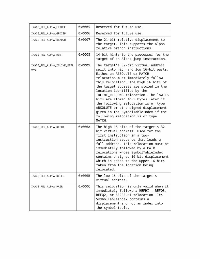
Alpha ProcessorsThe following relocation Type indicators are defined for Alpha processors:
Constant Value Description
IMAGE_REL_ALPHA_ABSOLUTE 0x0000 This relocation is ignored.
IMAGE_REL_ALPHA_REFLONG 0x0001 The target’s 32-bit virtual address. This fixup is illegal in a PE32+ image unless the image has been sandboxed by clearing the IMAGE_FILE_LARGE_ADDRESS_AWARE bit in the File Header.
IMAGE_REL_ALPHA_REFQUAD 0x0002 The target’s 64-bit virtual address.
IMAGE_REL_ALPHA_GPREL32 0x0003 32-bit signed displacement of the target relative to the Global Pointer (GP) register.
IMAGE_REL_ALPHA_LITERAL 0x0004 16-bit signed displacement of the target relative to the Global Pointer (GP) register.
IMAGE_REL_ALPHA_LITUSE 0x0005 Reserved for future use.
IMAGE_REL_ALPHA_GPDISP 0x0006 Reserved for future use.
IMAGE_REL_ALPHA_BRADDR 0x0007 The 21-bit relative displacement to the target. This supports the Alpha relative branch instructions.
IMAGE_REL_ALPHA_HINT 0x0008 14-bit hints to the processor for the target of an Alpha jump instruction.

IMAGE_REL_ALPHA_INLINE_REFL
ONG
0x0009 The target’s 32-bit virtual address split into high and low 16-bit parts. Either an ABSOLUTE or MATCH relocation must immediately follow this relocation. The high 16 bits of the target address are stored in the location identified by the INLINE_REFLONG relocation. The low 16 bits are stored four bytes later if the following relocation is of type ABSOLUTE or at a signed displacement given in the SymbolTableIndex if the following relocation is of type MATCH.
IMAGE_REL_ALPHA_REFHI 0x000A The high 16 bits of the target’s 32-bit virtual address. Used for the first instruction in a two-instruction sequence that loads a full address. This relocation must be immediately followed by a PAIR relocations whose SymbolTableIndex contains a signed 16-bit displacement which is added to the upper 16 bits taken from the location being relocated.
IMAGE_REL_ALPHA_REFLO 0x000B The low 16 bits of the target’s virtual address.
IMAGE_REL_ALPHA_PAIR 0x000C This relocation is only valid when it immediately follows a REFHI , REFQ3, REFQ2, or SECRELHI relocation. Its SymbolTableIndex contains a displacement and not an index into the symbol table.
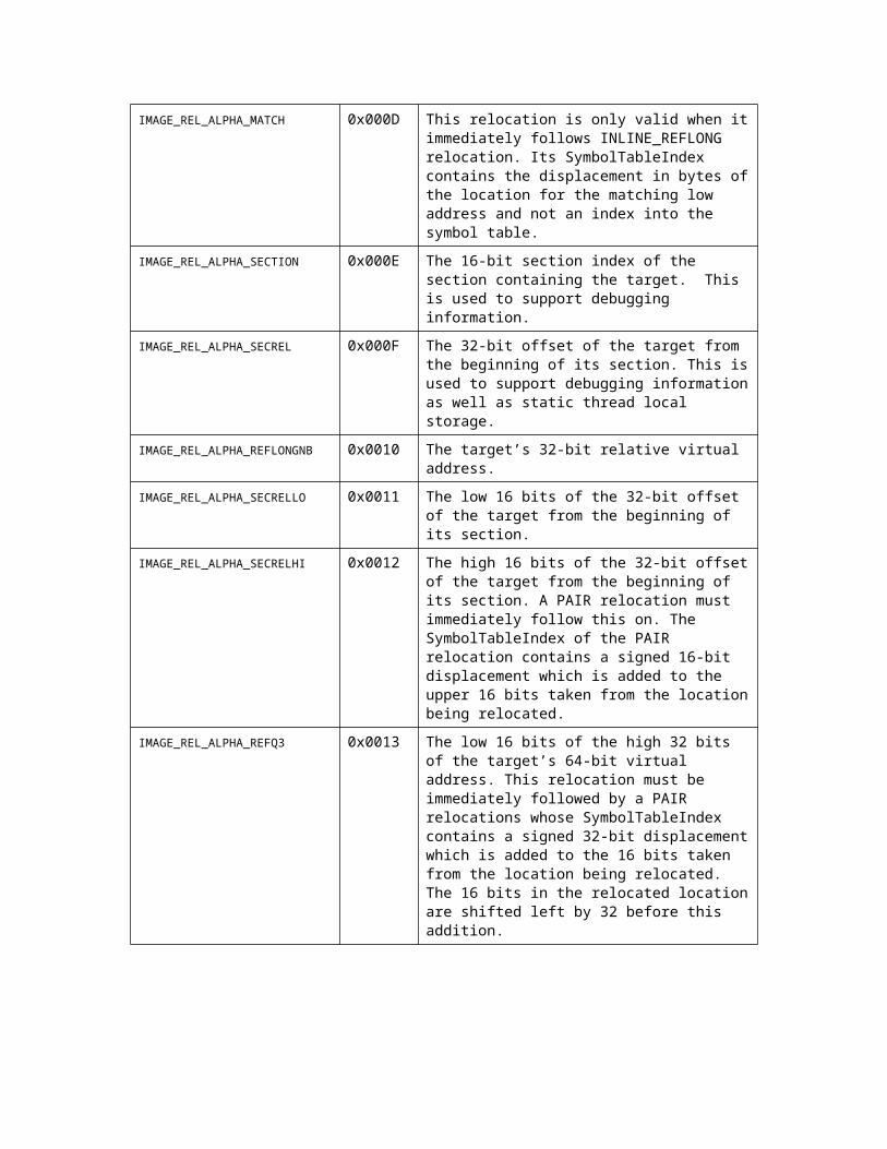
IMAGE_REL_ALPHA_MATCH 0x000D This relocation is only valid when it immediately follows INLINE_REFLONG relocation. Its SymbolTableIndex contains the displacement in bytes of the location for the matching low address and not an index into the symbol table.
IMAGE_REL_ALPHA_SECTION 0x000E The 16-bit section index of the section containing the target. This is used to support debugging information.
IMAGE_REL_ALPHA_SECREL 0x000F The 32-bit offset of the target from the beginning of its section. This is used to support debugging information as well as static thread local storage.
IMAGE_REL_ALPHA_REFLONGNB 0x0010 The target’s 32-bit relative virtual address.
IMAGE_REL_ALPHA_SECRELLO 0x0011 The low 16 bits of the 32-bit offset of the target from the beginning of its section.

IMAGE_REL_ALPHA_SECRELHI 0x0012 The high 16 bits of the 32-bit offset of the target from the beginning of its section. A PAIR relocation must immediately follow this on. The SymbolTableIndex of the PAIR relocation contains a signed 16-bit displacement which is added to the upper 16 bits taken from the location being relocated.
IMAGE_REL_ALPHA_REFQ3 0x0013 The low 16 bits of the high 32 bits of the target’s 64-bit virtual address. This relocation must be immediately followed by a PAIR relocations whose SymbolTableIndex contains a signed 32-bit displacement which is added to the 16 bits taken from the location being relocated. The 16 bits in the relocated location are shifted left by 32 before this addition.
IMAGE_REL_ALPHA_REFQ2 0x0014 The high 16 bits of the low 32 bits of the target’s 64-bit virtual address. This relocation must be immediately followed by a PAIR relocations whose SymbolTableIndex contains a signed 16-bit displacement which is added to the upper 16 bits taken from the location being relocated.
IMAGE_REL_ALPHA_REFQ1 0x0015 The low 16 bits of the target’s 64-bit virtual address.
IMAGE_REL_ALPHA_GPRELLO 0x0016 The low 16 bits of the 32-bit signed displacement of the target relative to the Global Pointer (GP) register.
IMAGE_REL_ALPHA_GPRELHI 0x0017 The high 16 bits of the 32-bit signed displacement of the target relative to the Global Pointer (GP) register.
IBM PowerPC ProcessorsThe following relocation Type indicators are defined for PowerPC processors:
Constant Value Description
IMAGE_REL_PPC_ABSOLUTE 0x0000 This relocation is ignored.
IMAGE_REL_PPC_ADDR64 0x0001 The target’s 64-bit virtual address.
IMAGE_REL_PPC_ADDR32 0x0002 The target’s 32-bit virtual address.
IMAGE_REL_PPC_ADDR24 0x0003 The low 24 bits of the target’s virtual address. This is only valid when the target symbol is absolute and can be sign extended to its original value.
IMAGE_REL_PPC_ADDR16 0x0004 The low 16 bits of the target’s virtual address.

IMAGE_REL_PPC_ADDR14 0x0005 The low 14 bits of the target’s virtual address. This is only valid when the target symbol is absolute and can be sign extended to its original value.
IMAGE_REL_PPC_REL24 0x0006 A 24-bit PC-relative offset to the symbol’s location.
IMAGE_REL_PPC_REL14 0x0007 A 14-bit PC-relative offset to the symbol’s location.
IMAGE_REL_PPC_ADDR32NB 0x000A The target’s 32-bit relative virtual address.
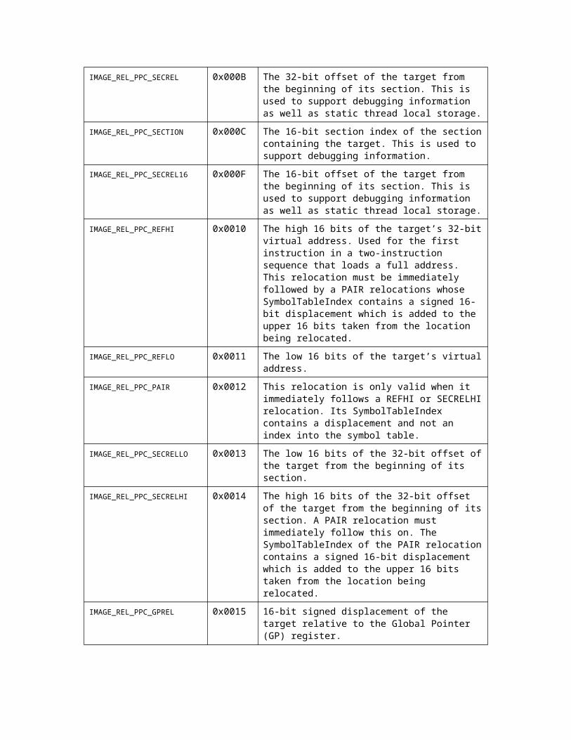
IMAGE_REL_PPC_SECREL 0x000B The 32-bit offset of the target from the beginning of its section. This is used to support debugging information as well as static thread local storage.
IMAGE_REL_PPC_SECTION 0x000C The 16-bit section index of the section containing the target. This is used to support debugging information.
IMAGE_REL_PPC_SECREL16 0x000F The 16-bit offset of the target from the beginning of its section. This is used to support debugging information as well as static thread local storage.
IMAGE_REL_PPC_REFHI 0x0010 The high 16 bits of the target’s 32-bit virtual address. Used for the first instruction in a two-instruction sequence that loads a full address. This relocation must be immediately followed by a PAIR relocations whose SymbolTableIndex contains a signed 16-bit displacement which is added to the upper 16 bits taken from the location being relocated.
IMAGE_REL_PPC_REFLO 0x0011 The low 16 bits of the target’s virtual address.
IMAGE_REL_PPC_PAIR 0x0012 This relocation is only valid when it immediately follows a REFHI or SECRELHI relocation. Its SymbolTableIndex contains a displacement and not an index into the symbol table.
IMAGE_REL_PPC_SECRELLO 0x0013 The low 16 bits of the 32-bit offset of the target from the beginning of its section.
IMAGE_REL_PPC_SECRELHI 0x0014 The high 16 bits of the 32-bit offset of the target from the beginning of its section. A PAIR relocation must immediately follow this on. The SymbolTableIndex of the PAIR relocation contains a signed 16-bit displacement which is added to the upper 16 bits taken from the location being relocated.
IMAGE_REL_PPC_GPREL 0x0015 16-bit signed displacement of the target relative to the Global Pointer (GP) register.
Hitachi SuperH ProcessorsThe following relocation type indicators are defined for SH3 and SH4 processors:
Constant Value Description

IMAGE_REL_SH3_ABSOLUTE 0x0000 This relocation is ignored.
IMAGE_REL_SH3_DIRECT16 0x0001 Reference to the 16-bit location that contains the virtual address of the target symbol.
IMAGE_REL_SH3_DIRECT32 0x0002 The target’s 32-bit virtual address.
IMAGE_REL_SH3_DIRECT8 0x0003 Reference to the 8-bit location that contains the virtual address of the target symbol.
IMAGE_REL_SH3_DIRECT8_WORD 0x0004 Reference to the 8-bit instruction that contains the effective 16-bit virtual address of the target symbol.
IMAGE_REL_SH3_DIRECT8_LONG 0x0005 Reference to the 8-bit instruction that contains the effective 32-bit virtual address of the target symbol.
IMAGE_REL_SH3_DIRECT4 0x0006 Reference to the 8-bit location whose low 4 bits contain the virtual address of the target symbol.
IMAGE_REL_SH3_DIRECT4_WORD 0x0007 Reference to the 8-bit instruction whose low 4 bits contain the effective 16-bit virtual address of the target symbol.
IMAGE_REL_SH3_DIRECT4_LONG 0x0008 Reference to the 8-bit instruction whose low 4 bits contain the effective 32-bit virtual address of the target symbol.
IMAGE_REL_SH3_PCREL8_WORD 0x0009 Reference to the 8-bit instruction which contains the effective 16-bit relative offset of the target symbol.
IMAGE_REL_SH3_PCREL8_LONG 0x000A Reference to the 8-bit instruction which contains the effective 32-bit relative offset of the target symbol.
IMAGE_REL_SH3_PCREL12_WORD 0x000B Reference to the 16-bit instruction whose low 12 bits contain the effective 16-bit relative offset of the target symbol.
IMAGE_REL_SH3_STARTOF_SECTION 0x000C Reference to a 32-bit location that is the virtual address of the symbol’s section.
IMAGE_REL_SH3_SIZEOF_SECTION 0x000D Reference to the 32-bit location that is the size of the symbol’s section.
IMAGE_REL_SH3_SECTION 0x000E The 16-bit section index of the section containing the target. This is used to support debugging information.
IMAGE_REL_SH3_SECREL 0x000F The 32-bit offset of the target from the beginning of its section. This is used to support debugging information as well as static thread local storage.
IMAGE_REL_SH3_DIRECT32_NB 0x0010 The target’s 32-bit relative virtual address.
ARM ProcessorsThe following relocation Type indicators are defined for ARM processors:
Constant Value Description
IMAGE_REL_ARM_ABSOLUTE 0x0000 This relocation is ignored.
IMAGE_REL_ARM_ADDR32 0x0001 The target’s 32-bit virtual address.
IMAGE_REL_ARM_ADDR32NB 0x0002 The target’s 32-bit relative virtual address.
IMAGE_REL_ARM_BRANCH24 0x0003 The 24-bit relative displacement to the target.
IMAGE_REL_ARM_BRANCH11 0x0004 Reference to a subroutine call, consisting of two 16-bit instructions with 11-bit offsets.
IMAGE_REL_ARM_SECTION 0x000E The 16-bit section index of the section containing the target. This is used to support debugging information.
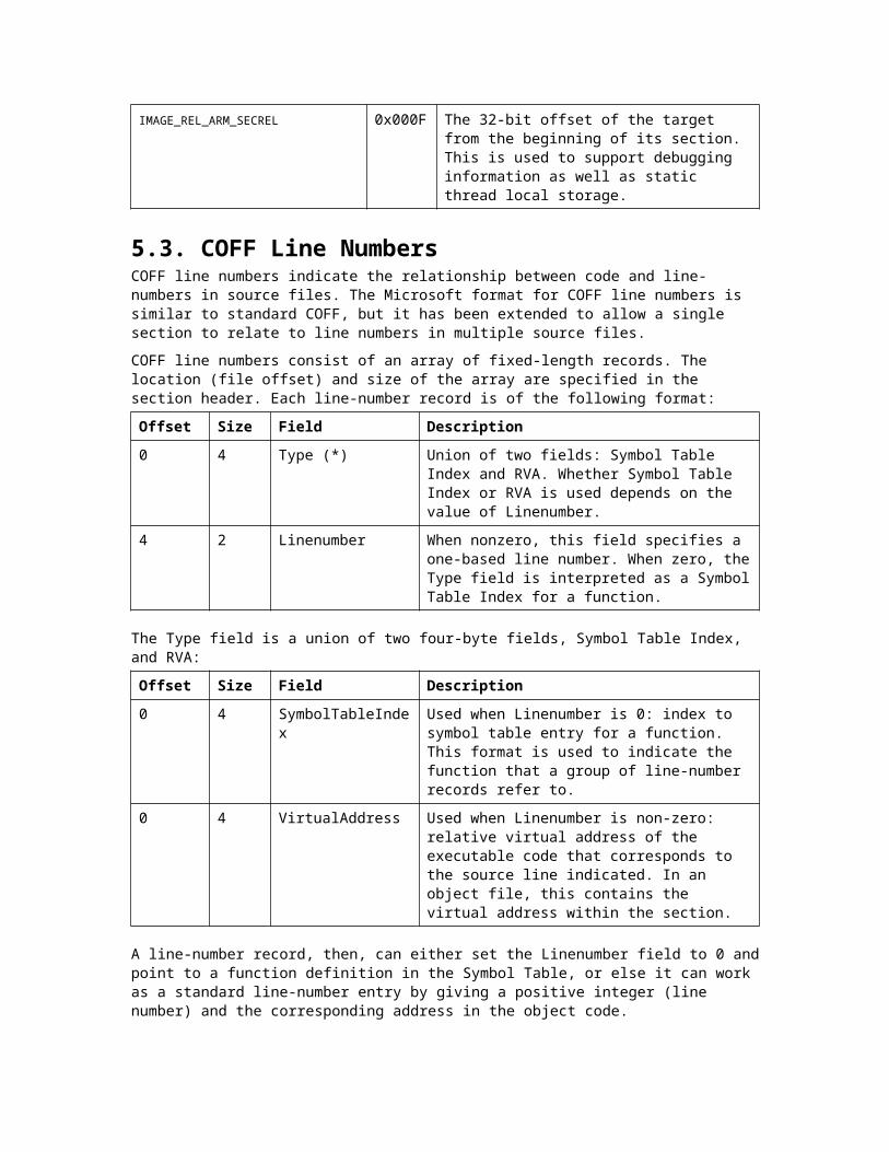
IMAGE_REL_ARM_SECREL 0x000F The 32-bit offset of the target from the beginning of its section. This is used to support debugging information as well as static thread local storage.
5.3. COFF Line NumbersCOFF line numbers indicate the relationship between code and line-numbers in source files. The Microsoft format for COFF line numbers is similar to standard COFF, but it has been extended to allow a single section to relate to line numbers in multiple source files.
COFF line numbers consist of an array of fixed-length records. The location (file offset) and size of the array are specified in the section header. Each line-number record is of the following format:
Offset Size Field Description
0 4 Type (*) Union of two fields: Symbol Table Index and RVA. Whether Symbol Table Index or RVA is used depends on the value of Linenumber.
4 2 Linenumber When nonzero, this field specifies a one-based line number. When zero, the Type field is interpreted as a Symbol Table Index for a function.
The Type field is a union of two four-byte fields, Symbol Table Index, and RVA:
Offset Size Field Description
0 4 SymbolTableIndex Used when Linenumber is 0: index to symbol table entry for a function. This format is used to indicate the function that a group of line-number records refer to.
0 4 VirtualAddress Used when Linenumber is non-zero: relative virtual address of the executable code that corresponds to the source line indicated. In an object file, this contains the virtual address within the section.
A line-number record, then, can either set the Linenumber field to 0 and point to a function definition in the Symbol Table, or else it can work as a standard line-number entry by giving a positive integer (line number) and the corresponding address in the object code.
A group of line-number entries always begins with the first format: the index of a function symbol. If this is the first line-number record in the section, then it is also the COMDAT symbol name for the function if the section’s COMDAT flag is set. (See Section 5.5.6, “COMDAT Sections.”) The function’s auxiliary record in the Symbol Table has a Pointer to Linenumbers field that points to this same line-number record.
A record identifying a function is followed by any number of line-number entries that give actual line-number information (Linenumber greater than zero). These entries are one-based, relative to the beginning of the function, and represent every source line in the function except for the first one.
For example, the first line-number record for the following example would specify the ReverseSign function (Symbol Table Index of ReverseSign, Linenumber set to 0). Then records with Linenumber values of 1, 2, and 3 would follow, corresponding to source lines as shown:// some code precedes ReverseSign function
int ReverseSign(int i)1: {2: return -1 * i;3: }
5.4. COFF Symbol TableThe Symbol Table described in this section is inherited from the traditional COFF format. It is distinct from CodeView® information. A file may contain both a COFF Symbol Table and CodeView debug information, and the two are kept separate. Some Microsoft tools use the Symbol Table for limited but important purposes, such as communicating COMDAT information to the linker. Section names and file names, as well as code and data symbols, are listed in the Symbol Table.
The location of the Symbol Table is indicated in the COFF Header.

The Symbol Table is an array of records, each 18 bytes long. Each record is either a standard or auxiliary symbol-table record. A standard record defines a symbol or name, and has the following format:
Offset Size Field Description
0 8 Name (*) Name of the symbol, represented by union of three structures. An array of eight bytes is used if the name is not more than eight bytes long. See Section 5.4.1, “Symbol Name Representation, ” for more information.
8 4 Value Value associated with the symbol. The interpretation of this field depends on Section Number and Storage Class. A typical meaning is the relocatable address.
12 2 SectionNumber Signed integer identifying the section, using a one-based index into the Section Table. Some values have special meaning defined in “Section Number Values.”
14 2 Type A number representing type. Microsoft tools set this field to 0x20 (function) or 0x0 (not a function). See Section 5.4.3, “Type Representation,” for more information.
16 1 StorageClass Enumerated value representing storage class. See Section 5.4.4, “Storage Class,” for more information.
17 1 NumberOfAuxSymbols Number of auxiliary symbol table entries that follow this record.
Zero or more auxiliary symbol-table records immediately follow each standard symbol-table record. However, typically not more than one auxiliary symbol-table record follows a standard symbol-table record (except for .file records with long file names). Each auxiliary record is the same size as a standard symbol-table record (18 bytes), but rather than define a new symbol, the auxiliary record gives additional information on the last symbol defined. The choice of which of several formats to use depends on the Storage Class field. Currently defined formats for auxiliary symbol table records are shown in “Auxiliary Symbol Records.”
Tools that read COFF symbol tables must ignore auxiliary symbol records whose interpretation is unknown. This allows the symbol table format to be extended to add new auxiliary records, without breaking existing tools.
5.4.1. Symbol Name RepresentationThe Name field in a symbol table consists of eight bytes that contain the name itself, if not too long, or else give an offset into the String Table. To determine whether the name itself or an offset is given, test the first four bytes for equality to zero.
Offset Size Field Description
0 8 Short Name An array of eight bytes. This array is padded with nulls on the right if the name is less than eight bytes long.
0 4 Zeroes Set to all zeros if the name is longer than eight bytes.
4 4 Offset Offset into the String Table.
5.4.2. Section Number ValuesNormally, the Section Value field in a symbol table entry is a one-based index into the Section Table. However, this field is a signed integer and may take negative values. The following values, less than one, have special meanings:
Constant Value Description
IMAGE_SYM_UNDEFINED 0 Symbol record is not yet assigned a section. If the value is 0 this indicates a references to an external symbol defined elsewhere. If the value is non-zero this is a common symbol with a size specified by the value.
IMAGE_SYM_ABSOLUTE -1 The symbol has an absolute (non-relocatable) value and is not an address.
IMAGE_SYM_DEBUG -2 The symbol provides general type or debugging information but does not correspond to a section. Microsoft tools use this setting along with .file records (storage class FILE).
5.4.3. Type RepresentationThe Type field of a symbol table entry contains two bytes, each byte representing type information. The least-significant byte represents simple (base) data type, and the most-significant byte represents complex type, if any:
MSB LSB
Complex type: none, pointer, function, array. Base type: integer, floating-point, etc.

The following values are defined for base type, although Microsoft tools generally do not use this field, setting the least-significant byte to 0. Instead, CodeView information is used to indicate types. However, the possible COFF values are listed here for completeness.
Constant Value Description
IMAGE_SYM_TYPE_NULL 0 No type information or unknown base type. Microsoft tools use this setting.
IMAGE_SYM_TYPE_VOID 1 No valid type; used with void pointers and functions.
IMAGE_SYM_TYPE_CHAR 2 Character (signed byte).
IMAGE_SYM_TYPE_SHORT 3 Two-byte signed integer.
IMAGE_SYM_TYPE_INT 4 Natural integer type (normally four bytes in Windows NT).
IMAGE_SYM_TYPE_LONG 5 Four-byte signed integer.
IMAGE_SYM_TYPE_FLOAT 6 Four-byte floating-point number.
IMAGE_SYM_TYPE_DOUBLE 7 Eight-byte floating-point number.
IMAGE_SYM_TYPE_STRUCT 8 Structure.
IMAGE_SYM_TYPE_UNION 9 Union.
IMAGE_SYM_TYPE_ENUM 10 Enumerated type.
IMAGE_SYM_TYPE_MOE 11 Member of enumeration (a specific value).
IMAGE_SYM_TYPE_BYTE 12 Byte; unsigned one-byte integer.
IMAGE_SYM_TYPE_WORD 13 Word; unsigned two-byte integer.
IMAGE_SYM_TYPE_UINT 14 Unsigned integer of natural size (normally, four bytes).
IMAGE_SYM_TYPE_DWORD 15 Unsigned four-byte integer.
The most significant byte specifies whether the symbol is a pointer to, function returning, or array of the base type specified in the least significant byte. Microsoft tools use this field only to indicate whether or not the symbol is a function, so that the only two resulting values are 0x0 and 0x20 for the Type field. However, other tools can use this field to communicate more information.
It is very important to specify the function attribute correctly. This information is required for incremental linking to work correctly. For some architectures the information may be required for other purposes.
Constant Value Description
IMAGE_SYM_DTYPE_NULL 0 No derived type; the symbol is a simple scalar variable.
IMAGE_SYM_DTYPE_POINTER 1 Pointer to base type.
IMAGE_SYM_DTYPE_FUNCTION 2 Function returning base type.
IMAGE_SYM_DTYPE_ARRAY 3 Array of base type.

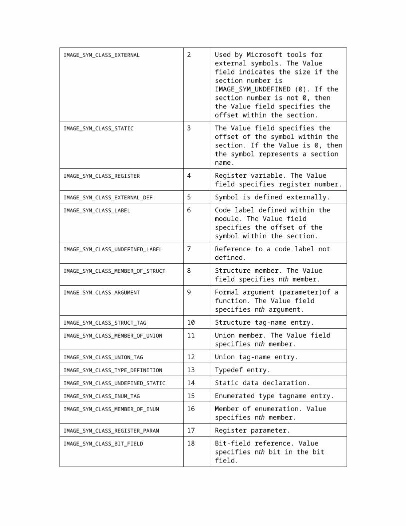
5.4.4. Storage ClassThe Storage Class field of the Symbol Table indicates what kind of definition a symbol represents. The following table shows possible values. Note that the Storage Class field is an unsigned one-byte integer. The special value -1 should therefore be taken to mean its unsigned equivalent, 0xFF.
Although traditional COFF format makes use of many storage-class values, Microsoft tools rely on CodeView format for most symbolic information and generally use only four storage-class values: EXTERNAL (2), STATIC (3), FUNCTION (101), and STATIC (103). Except in the second column heading below, “Value” should be taken to mean the Value field of the symbol record (whose interpretation depends on the number found as the storage class).
Constant Value Description / Interpretation of Value Field
IMAGE_SYM_CLASS_END_OF_FUNCTION -1 (0xFF)
Special symbol representing end of function, for debugging purposes.
IMAGE_SYM_CLASS_NULL 0 No storage class assigned.
IMAGE_SYM_CLASS_AUTOMATIC 1 Automatic (stack) variable. The Value field specifies stack frame offset.
IMAGE_SYM_CLASS_EXTERNAL 2 Used by Microsoft tools for external symbols. The Value field indicates the size if the section number is IMAGE_SYM_UNDEFINED (0). If the section number is not 0, then the Value field specifies the offset within the section.
IMAGE_SYM_CLASS_STATIC 3 The Value field specifies the offset of the symbol within the section. If the Value is 0, then the symbol represents a section name.
IMAGE_SYM_CLASS_REGISTER 4 Register variable. The Value field specifies register number.
IMAGE_SYM_CLASS_EXTERNAL_DEF 5 Symbol is defined externally.
IMAGE_SYM_CLASS_LABEL 6 Code label defined within the module. The Value field specifies the offset of the symbol within the section.
IMAGE_SYM_CLASS_UNDEFINED_LABEL 7 Reference to a code label not defined.
IMAGE_SYM_CLASS_MEMBER_OF_STRUCT 8 Structure member. The Value field specifies nth member.
IMAGE_SYM_CLASS_ARGUMENT 9 Formal argument (parameter)of a function. The Value field specifies nth argument.
IMAGE_SYM_CLASS_STRUCT_TAG 10 Structure tag-name entry.
IMAGE_SYM_CLASS_MEMBER_OF_UNION 11 Union member. The Value field specifies nth member.
IMAGE_SYM_CLASS_UNION_TAG 12 Union tag-name entry.
IMAGE_SYM_CLASS_TYPE_DEFINITION 13 Typedef entry.
IMAGE_SYM_CLASS_UNDEFINED_STATIC 14 Static data declaration.
IMAGE_SYM_CLASS_ENUM_TAG 15 Enumerated type tagname entry.
IMAGE_SYM_CLASS_MEMBER_OF_ENUM 16 Member of enumeration. Value specifies nth member.
IMAGE_SYM_CLASS_REGISTER_PARAM 17 Register parameter.
IMAGE_SYM_CLASS_BIT_FIELD 18 Bit-field reference. Value specifies nth bit in the bit field.
IMAGE_SYM_CLASS_BLOCK 100 A .bb (beginning of block) or .eb (end of block) record. Value is the relocatable address of the code location.
IMAGE_SYM_CLASS_FUNCTION 101 Used by Microsoft tools for symbol records that define the extent of a function: begin function (named .bf), end function (.ef), and lines in function (.lf). For .lf records, Value gives the number of source lines in the function. For .ef records, Value gives the size of function code.
IMAGE_SYM_CLASS_END_OF_STRUCT 102 End of structure entry.
IMAGE_SYM_CLASS_FILE 103 Used by Microsoft tools, as well as traditional COFF format, for the source-file symbol record. The symbol is followed by auxiliary records that name the file.
IMAGE_SYM_CLASS_SECTION 104 Definition of a section (Microsoft tools use STATIC storage class instead).
IMAGE_SYM_CLASS_WEAK_EXTERNAL 105 Weak external. See Section 5.5.3, “Auxiliary Format 3: Weak Externals,” for more information.
5.5. Auxiliary Symbol RecordsAuxiliary Symbol Table records always follow and apply to some standard Symbol Table record. An auxiliary record can have any format that the tools are designed to recognize, but 18 bytes must be allocated for them so that Symbol Table is maintained as an array of regular size. Currently, Microsoft tools recognize auxiliary formats for the following kinds of records: function definitions, function begin and end symbols (.bf and .ef), weak externals, filenames, and section definitions.
The traditional COFF design also includes auxiliary-record formats for arrays and structures. Microsoft tools do not use these, and instead place that symbolic information in CodeView format in the debug sections.

5.5.1. Auxiliary Format 1: Function DefinitionsA symbol table record marks the beginning of a function definition if all of the following are true: it has storage class EXTERNAL (2), a Type value indicating it is a function (0x20), and a section number greater than zero. Note that a symbol table record that has a section number of UNDEFINED (0) does not define the function and does not have an auxiliary record. Function-definition symbol records are followed by an auxiliary record with the format described below.
Offset Size Field Description
0 4 TagIndex Symbol-table index of the corresponding .bf (begin function) symbol record.
4 4 TotalSize Size of the executable code for the function itself. If the function is in its own section, the Size of Raw Data in the section header will be greater or equal to this field, depending on alignment considerations.
8 4 PointerToLinenumber File offset of the first COFF line-number entry for the function, or zero if none exists. See Section 5.3, “COFF Line Numbers,” for more information.
12 4 PointerToNextFunction Symbol-table index of the record for the next function. If the function is the last in the symbol table, this field is set to zero.
16 2 Unused.
5.5.2. Auxiliary Format 2: .bf and .ef SymbolsFor each function definition in the Symbol Table, there are three contiguous items that describe the beginning, ending, and number of lines. Each of these symbols has storage class FUNCTION (101):
1 A symbol record named .bf (begin function). The Value field is unused.
2 A symbol record named .lf (lines in function). The Value field gives the number of lines in the function.
3 A symbol record named .ef (end of function). The Value field has the same number as the Total Size field in the function-definition symbol record.
The .bf and .ef symbol records (but not .lf records) are followed by an auxiliary record with the following format:

Offset Size Field Description
0 4 Unused.
4 2 Linenumber Actual ordinal line number (1, 2, 3, etc.) within source file, corresponding to the .bf or .ef record.
6 6 Unused.
12 4 PointerToNextFunction (.bf only)
Symbol-table index of the next .bf symbol record. If the function is the last in the symbol table, this field is set to zero. Not used for .ef records.
16 2 Unused.
5.5.3. Auxiliary Format 3: Weak Externals“Weak externals” are a mechanism for object files allowing flexibility at link time. A module can contain an unresolved external symbol (sym1), but it can also include an auxiliary record indicating that if sym1 is not present at link time, another external symbol (sym2) is used to resolve references instead.
If a definition of sym1 is linked, then an external reference to the symbol is resolved normally. If a definition of sym1 is not linked, then all references to the weak external for sym1 refer to sym2 instead. The external symbol, sym2, must always be linked; typically it is defined in the module containing the weak reference to sym1.
Weak externals are represented by a Symbol Table record with EXTERNAL storage class, UNDEF section number, and a value of 0. The weak-external symbol record is followed by an auxiliary record with the following format:
Offset Size Field Description
0 4 TagIndex Symbol-table index of sym2, the symbol to be linked if sym1 is not found.
4 4 Characteristics A value of IMAGE_WEAK_EXTERN_SEARCH_NOLIBRARY indicates that no library search for sym1 should be performed.
A value of IMAGE_WEAK_EXTERN_SEARCH_LIBRARY indicates that a library search for sym1 should be performed.
A value of IMAGE_WEAK_EXTERN_SEARCH_ALIAS indicates that sym1 is an alias for sym2.

8 10 Unused.
Note that the Characteristics field is not defined in WINNT.H; instead, the Total Size field is used.
5.5.4. Auxiliary Format 4: FilesThis format follows a symbol-table record with storage class FILE (103). The symbol name itself should be .file, and the auxiliary record that follows it gives the name of a source-code file.
Offset Size Field Description
0 18 File Name ASCII string giving the name of the source file; padded with nulls if less than maximum length.
5.5.5. Auxiliary Format 5: Section DefinitionsThis format follows a symbol-table record that defines a section: such a record has a symbol name that is the name of a section (such as .text or .drectve) and has storage class STATIC (3). The auxiliary record provides information on the section referred to. Thus it duplicates some of the information in the section header.
Offset Size Field Description
0 4 Length Size of section data; same as Size of Raw Data in the section header.
4 2 NumberOfRelocations Number of relocation entries for the section.
6 2 NumberOfLinenumbers Number of line-number entries for the section.
8 4 Check Sum Checksum for communal data. Applicable if the IMAGE_SCN_LNK_COMDAT flag is set in the section header. See “COMDAT Sections” below, for more information.
12 2 Number One-based index into the Section Table for the associated section; used when the COMDAT Selection setting is 5.
14 1 Selection COMDAT selection number. Applicable if the section is a COMDAT section.
15 3 Unused.
5.5.6. COMDAT Sections (Object Only)The Selection field of the Section Definition auxiliary format is applicable if the section is a COMDAT section: a section that can be defined by more than one object file. (The flag IMAGE_SCN_LNK_COMDAT is set in the Section Flags field of the section header.) The Selection field determines the way that the linker resolves the multiple definitions of COMDAT sections.
The first symbol having the section value of the COMDAT section must be the section symbol. This symbol has the name of the section, Value field equal to 0, the section number of the COMDAT section in question, Type field equal to IMAGE_SYM_TYPE_NULL, Class field equal

to IMAGE_SYM_CLASS_STATIC, and one auxiliary record. The second symbol is called “the COMDAT symbol” and is used by the linker in conjunction with the Selection field.
Values for the Selection field are shown below.
Constant Value Description
IMAGE_COMDAT_SELECT_NODUPLICATES 1 The linker issues a multiply defined symbol error if this symbol is already defined.
IMAGE_COMDAT_SELECT_ANY 2 Any section defining the same COMDAT symbol may be linked; the rest are removed.
IMAGE_COMDAT_SELECT_SAME_SIZE 3 The linker chooses an arbitrary section among the definitions for this symbol. A multiply defined symbol error is issued if all definitions don’t have the same size.
IMAGE_COMDAT_SELECT_EXACT_MATCH 4 The linker chooses an arbitrary section among the definitions for this symbol. A multiply defined symbol error is issued if all definitions don’t match exactly.
IMAGE_COMDAT_SELECT_ASSOCIATIVE 5 The section is linked if a certain other COMDAT section is linked. This other section is indicated by the Number field of the auxiliary symbol record for the section definition. Use of this setting is useful for definitions that have components in multiple sections (for example, code in one and data in another), but where all must be linked or discarded as a set.
IMAGE_COMDAT_SELECT_LARGEST 6 The linker chooses the largest from the definitions for this symbol. If multiple definitions have this size the choice between them is arbitrary.
5.6. COFF String TableImmediately following the COFF symbol table is the COFF string table. The position of this table is found by taking the symbol table address in the COFF header, and adding the number of symbols multiplied by the size of a symbol.
At the beginning of the COFF string table are 4 bytes containing the total size (in bytes) of the rest of the string table. This size includes the size field itself, so that the value in this location would be 4 if no strings were present.
Following the size are null-terminated strings pointed to by symbols in the COFF symbol table.
5.7. The Attribute Certificate Table (Image Only)Attribute Certificates may be associated with an image by adding an Attribute Certificate Table. There are a number of different types of Attribute Certificates. The meaning and use of each

certificate type is not covered in this document. For this information see the Microsoft Distributed System Architecture, Attribute Certificate Architecture Specification.
An Attribute Certificate Table is added at the end of the image, with only a .debug section following (if a .debug section is present). The Attribute Certificate Table contains one or more fixed length table entries which can be found via the Certificate Table field of the Optional Header Data Directories list (offset 128). Each entry of this table identifies the beginning location and length of a corresponding certificate. There is one Certificate Table entry for each certificate stored in this section. The number of entries in the certificate table can be calculated by dividing the size of the certificate table (found in offset 132) by the size of an entry in the certificate table (8). Note that the size of the certificate table includes only the table entries, not the actual certificates which the table entries, in turn, point to.
The format of each table entry is:
Offset Size Field Description
0 4 Certificate Data File pointer to the certificate data. This will always point to an address that is octaword aligned (i.e., is a multiple of 8 bytes and so the low-order 3 bits are zero).
0 4 Size of Certificate Unsigned integer identifying the size (in bytes) of the certificate.
Notice that certificates always start on an octaword boundary. If a certificate is not an even number of octawords long, it is zero padded to the next octaword boundary. However, the length of the certificate does not include this padding and so any certificate navigation software must be sure to round up to the next octaword to locate another certificate.
5.7.1. Certificate DataThis is the binary data representing an Attribute Certificate. The format and meaning of each certificate is defined in Attribute Certificate Architecture Specification. The certificate starting location and length is specified by an entry in the Certificate Table. Each certificate is represented by a single Certificate Table entry.
5.8 Delay-Load Import Tables (Image Only)These tables were added to the image in order to support a uniform mechanism for applications to delay the loading of a DLL until the first call into that DLL. The layout of the tables matches that of the traditional import tables (see Section “6.4. The .idata Section“ for details), so only a few details will be discussed here.
5.8.1. The Delay-Load Directory TableThe Delay-Load Directory Table is the counterpart to the Import Directory Table, and can be retrieved via the Delay Import Descriptor entry in the Optional Header Data Directories list (offset 200). The Table is arranged as follows:
Offset Size Field Description
0 4 Attributes Must be zero.
4 4 Name Relative virtual address of the name of the DLL to be loaded. The name resides in the read-only data section of the image.
8 4 Module Handle Relative virtual address of the module handle (in the data section of the image) of the DLL to be delay-loaded. Used for storage by the routine supplied to manage delay-loading.
12 4 Delay Import Address Table
Relative virtual address of the delay-load import address table. See below for further details.
16 4 Delay Import Name Table
Relative virtual address of the delay-load name table, which contains the names of the imports that may need to be loaded. Matches the layout of the Import Name Table, Section 6.4.3. Hint/Name Table.
20 4 Bound Delay Import Table
Relative virtual address of the bound delay-load address table, if it exists.
24 4 Unload Delay Import Table
Relative virtual address of the unload delay-load address table, if it exists. This is an exact copy of the Delay Import Address Table. In the event that the caller unloads the DLL, this table should be copied back over the Delay IAT such that subsequent calls to the DLL continue to use the thunking mechanism correctly.
28 4 Time Stamp Time stamp of DLL to which this image has been bound.
The tables referenced in this data structure are organized and sorted just as their counterparts are for traditional imports. See Section 6.4. The idata Section for details.
5.8.2. AttributesAs yet, there are no attribute flags defined. This field is currently set to zero by the linker in the image. This field can be used to extend the record by indicating the presence of new fields or for indicating behaviors to the delay and/or unload helper functions.
5.8.3. NameThe name of the DLL to be delay loaded resides in the read-only data section of the image and is referenced via the szName field.
5.8.4. Module handleThe handle of the DLL to be delay loaded is located in the data section of the image and pointed to via the phmod field. The supplied delay load helper uses this location to store the handle to the loaded DLL.

5.8.5. Delay Import Address Table (IAT)The delay IAT is referenced by the delay import descriptor via the pIAT field. This is the working copy of the entry point function pointers that resides in the data section of the image and initially refer to the delay load thunks. The delay load helper is responsible for updating these pointers with the real entry points so that the thunks are no longer in the calling loop. The function pointers are access via the expression pINT->u1.Function.
5.8.6. Delay Import Name Table (INT)The delay INT has the names of the imports that may need to be loaded. They are ordered in the same fashion as the function pointers in the IAT. They consist of the same structures as the standard INT and are accessed via the expression pINT->u1.AddressOfData->Name[0].
5.8.7. Delay Bound Import Address Table (BIAT) and Time StampThe delay BIAT is an optional table of IMAGE_THUNK_DATA items that is used along with the timestamp field by a post process binding phase.
5.8.8. Delay Unload Import Address Table (UIAT)The delay UIAT is an optional table of IMAGE_THUNK_DATA items that is used by the unload code to handle an explicit unload request. It is initialized data in the read-only section that is an exact copy of the original IAT that referred the code to the delay load thunks. On the unload request, the library can be freed, the *phmod cleared, and the UIAT written over the IAT to restore everything to its pre-load state.
6. Special SectionsTypical COFF sections contain code or data that linkers and Win32 loaders process without special knowledge of the sections’ contents. The contents are relevant only to the application being linked or executed.
However, some COFF sections have special meanings when found in object files and/or image files. Tools and loaders recognize these sections because they have special flags set in the section header, or because they are pointed to from special locations in the image optional header, or because the section name is “magic”: that is, the name indicates a special function of the section. (Even where the section name is not magic, the name is dictated by convention, so we will refer to a name.)
The reserved sections and their attributes are described in the table below, followed by detailed descriptions for a subset of them.
Section Name
Content Characteristics
.arch Alpha architecture information
IMAGE_SCN_MEM_READ | IMAGE_SCN_CNT_INITIALIZED_DATA | IMAGE_SCN_ALIGN_8BYTES | IMAGE_SCN_MEM_DISCARDABLE
.bss Uninitialized data IMAGE_SCN_CNT_UNINITIALIZED_DATA | IMAGE_SCN_MEM_READ | IMAGE_SCN_MEM_WRITE

.data Initialized data IMAGE_SCN_CNT_INITIALIZED_DATA | IMAGE_SCN_MEM_READ | IMAGE_SCN_MEM_WRITE
.edata Export tables IMAGE_SCN_CNT_INITIALIZED_DATA | IMAGE_SCN_MEM_READ
.idata Import tables IMAGE_SCN_CNT_INITIALIZED_DATA | IMAGE_SCN_MEM_READ |IMAGE_SCN_MEM_WRITE
.pdata Exception information
IMAGE_SCN_CNT_INITIALIZED_DATA | IMAGE_SCN_MEM_READ
.rdata Read-only initialized data
IMAGE_SCN_CNT_INITIALIZED_DATA | IMAGE_SCN_MEM_READ
.reloc Image relocations IMAGE_SCN_CNT_INITIALIZED_DATA | IMAGE_SCN_MEM_READ | IMAGE_SCN_MEM_DISCARDABLE
.rsrc Resource directory
IMAGE_SCN_CNT_INITIALIZED_DATA | IMAGE_SCN_MEM_READ | IMAGE_SCN_MEM_WRITE
.text Executable code IMAGE_SCN_CNT_CODE | IMAGE_SCN_MEM_EXECUTE | IIMAGE_SCN_MEM_READ
.tls Thread-local storage
IMAGE_SCN_CNT_INITIALIZED_DATA | IMAGE_SCN_MEM_READ | IMAGE_SCN_MEM_WRITE
.xdata Exception information
IMAGE_SCN_CNT_INITIALIZED_DATA | IMAGE_SCN_MEM_READ
Some of the sections listed here are marked “(object only)” or “(image only)” to indicate that their special semantics are relevant only for object files or image files, respectively. A section that says “(image only)” may still appear in an object file as a way of getting into the image file, but the section has no special meaning to the linker, only to the image file loader.
6.1. The .debug SectionThe .debug section is used in object files to contain compiler-generated debug information, and in image files to contain the total debug information generated. This section describes the packaging of debug information in object and image files. The actual format of CodeView debug information is not described here. See the document CV4 Symbolic Debug Information Specification.
The next section describes the format of the debug directory, which can be anywhere in the image. Subsequent sections describe the “groups” in object files that contain debug information.
The default for the linker is that debug information is not mapped into the address space of the image. A .debug section exists only when debug information is mapped in the address space.

6.1.1. Debug Directory (Image Only)Image files contain an optional “debug directory” indicating what form of debug information is present and where it is. This directory consists of an array of “debug directory entries” whose location and sizes are indicated in the image optional header.
The debug directory may be in a discardable .debug section (if one exists) or it may be included in any other section in the image file, or not in a section at all.
Each debug directory entry identifies the location and size of a block of debug information. The RVA specified may be 0 if the debug information is not covered by a section header (i.e., it resides in the image file and is not mapped into the run-time address space). If it is mapped, the RVA is its address.
Here is the format of a debug directory entry:
Offset Size Field Description
0 4 Characteristics A reserved field intended to be used for flags, set to zero for now.
4 4 TimeDateStamp Time and date the debug data was created.
8 2 MajorVersion Major version number of the debug data format.
10 2 MinorVersion Minor version number of the debug data format.
12 4 Type Format of debugging information: this field enables support of multiple debuggers. See Section 6.1.2, “Debug Type,” for more information.
16 4 SizeOfData Size of the debug data (not including the debug directory itself).
20 4 AddressOfRawData Address of the debug data when loaded, relative to the image base.
24 4 PointerToRawData File pointer to the debug data.
6.1.2. Debug TypeThe following values are defined for the Debug Type field of the debug directory:
Constant Value Description
IMAGE_DEBUG_TYPE_UNKNOWN 0 Unknown value, ignored by all tools.
IMAGE_DEBUG_TYPE_COFF 1 COFF debug information (line numbers, symbol table, and string table). This type of debug information is also pointed to by fields in the file headers.
IMAGE_DEBUG_TYPE_CODEVIEW 2 CodeView debug information. The format of the data block is described by the CV4 specification.

IMAGE_DEBUG_TYPE_FPO 3 Frame Pointer Omission (FPO) information. This information tells the debugger how to interpret non-standard stack frames, which use the EBP register for a purpose other than as a frame pointer.
IMAGE_DEBUG_TYPE_MISC 4
IMAGE_DEBUG_TYPE_EXCEPTION 5
IMAGE_DEBUG_TYPE_FIXUP 6
IMAGE_DEBUG_TYPE_OMAP_TO_SRC 7
IMAGE_DEBUG_TYPE_OMAP_FROM_SRC 8
IMAGE_DEBUG_TYPE_BORLAND 9
If Debug Type is set to IMAGE_DEBUG_TYPE_FPO, the debug raw data is an array in which each member describes the stack frame of a function. Not every function in the image file need have FPO information defined for it, even though debug type is FPO. Those functions that do not have FPO information are assumed to have normal stack frames. The format for FPO information is defined as follows:#define FRAME_FPO 0#define FRAME_TRAP 1#define FRAME_TSS 2
typedef struct _FPO_DATA { DWORD ulOffStart; // offset 1st byte of function code DWORD cbProcSize; // # bytes in function DWORD cdwLocals; // # bytes in locals/4 WORD cdwParams; // # bytes in params/4
WORD cbProlog : 8; // # bytes in prolog WORD cbRegs : 3; // # regs saved WORD fHasSEH : 1; // TRUE if SEH in func WORD fUseBP : 1; // TRUE if EBP has been allocated WORD reserved : 1; // reserved for future use WORD cbFrame : 2; // frame type} FPO_DATA;
6.1.3. .debug$F (Object Only)Object files can contain .debug$F sections whose contents are one or more FPO_DATA records (Frame Pointer Omission information). See “IMAGE_DEBUG_TYPE_FPO” in table above.
The linker recognizes these .debug$F records. If debug information is being generated, the linker sorts the FPO_DATA records by procedure RVA, and generates a debug directory entry for them.
The compiler should not generate FPO records for procedures that have a standard frame format.
6.1.4. .debug$S (Object Only)This section contains CV4 symbolic information: a stream of CV4 symbol records as described in the CV4 spec.

6.1.5. .debug$T (Object Only)This section contains CV4 type information: a stream of CV4 type records as described in the CV4 spec.
6.1.6. Linker Support for Microsoft CodeView® Debug InformationTo support CodeView debug information, the linker:
1 Generates the header and “NB05” signature.
2 Packages the header with .debug$S and .debug$T sections from object files and synthetic (linker-generated) CV4 information, and creates a debug directory entry.
3 Generates the subsection directory containing a pointer to each known subsection, including subsections that are linker-generated.
4 Generates the sstModules subsection, which specifies the address and size of each module’s contribution(s) to the image address space.
5 Generates the sstSegMap subsection, which specifies the address and size of each section in the image.
6 Generates the sstPublicSym subsection, which contains the name and address of all externally defined symbols. (A symbol may be represented both by .debug$S information and by an sstPublicSym entry.)
6.2. The .drectve Section (Object Only)A section is a “directive” section if it has the IMAGE_SCN_LNK_INFO flag set in the section header. By convention, such a section also has the name .drectve. The linker removes a .drectve section after processing the information, so the section does not appear in the image file being linked. Note that a section marked with IMAGE_SCN_LNK_INFO that is not named .drectve is ignored and discarded by the linker.
A .drectve section consists of a string of ASCII text. This string is a series of linker options (each option containing hyphen, option name, and any appropriate attribute) separated by spaces. The .drectve section must not have relocations or line numbers.
In a .drectve section, if the hyphen preceding an option is followed by a question mark (for example, “-?export”), and the option is not recognized as a valid directive, the linker must ignore it. This allows compilers and linkers to add new directives while maintaining compatibility with existing linkers, as long as the new directives are not required for the correct linking of the application. For example, if the directive enables a link-time optimization, it is acceptable if some linkers cannot recognize it.
6.3. The .edata Section (Image Only)The export data section, named .edata, contains information about symbols that other images can access through dynamic linking. Exports are generally found in DLLs, but DLLs can import symbols as well.
An overview of the general structure of the export section is described below. The tables described are generally contiguous in the file and present in the order shown (though this is not strictly required). Only the Directory Table and Address Table are necessary for exporting symbols as ordinals. (An ordinal is an export accessed directly as an Export Address Table

index.) The Name Pointer Table, Ordinal Table, and Export Name Table all exist to support use of export names.
Table Name Description
Export Directory Table A table with just one row (unlike the debug directory). This table indicates the locations and sizes of the other export tables.
Export Address Table An array of RVAs of exported symbols. These are the actual addresses of the exported functions and data within the executable code and data sections. Other image files can import a symbol by using an index to this table (an ordinal) or, optionally, by using the public name that corresponds to the ordinal if one is defined.
Name Pointer Table Array of pointers to the public export names, sorted in ascending order.
Ordinal Table Array of the ordinals that correspond to members of the Name Pointer Table. The correspondence is by position; therefore, the Name Pointer Table and the Ordinal Table must have the same number of members. Each ordinal is an index into the Export Address Table.
Export Name Table A series of null-terminated ASCII strings. Members of the Name Pointer Table point into this area. These names are the public names through which the symbols are imported and exported; they do not necessarily have to be the same as the private names used within the image file.
When another image file imports a symbol by name, the Name Pointer Table is searched for a matching string. If one is found, the associated ordinal is then determined by looking at the corresponding member in the Ordinal Table (that is, the member of the Ordinal Table with the same index as the string pointer found in the Name Pointer Table). The resulting ordinal is an index into the Export Address Table, which gives the actual location of the desired symbol. Every export symbol can be accessed by an ordinal.
Direct use of an ordinal is therefore more efficient, because it avoids the need to search the Name Pointer Table for a matching string. However, use of an export name is more mnemonic and does not require the user to know the table index for the symbol.
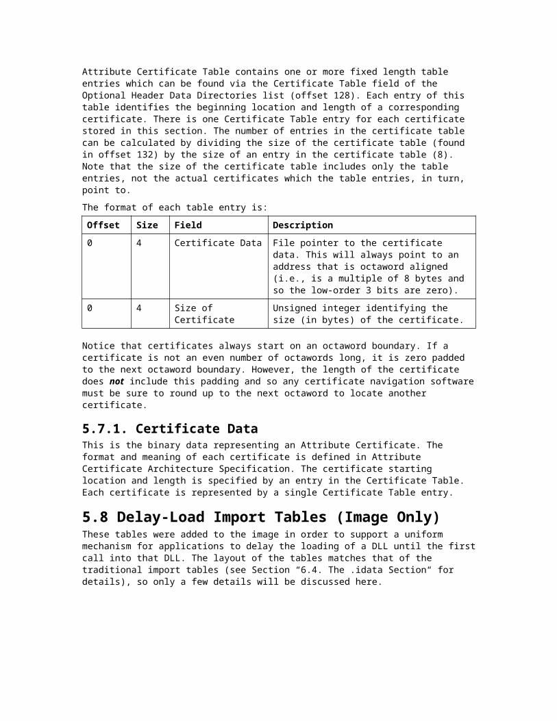
6.3.1. Export Directory TableThe export information begins with the Export Directory Table, which describes the remainder of the export information. The Export Directory Table contains address information that is used to resolve fix-up references to the entry points within this image.
Offset Size Field Description
0 4 Export Flags A reserved field, set to zero for now.
4 4 Time/Date Stamp Time and date the export data was created.
8 2 Major Version Major version number. The major/minor version number can be set by the user.
10 2 Minor Version Minor version number.
12 4 Name RVA Address of the ASCII string containing the name of the DLL. Relative to image base.
16 4 Ordinal Base Starting ordinal number for exports in this image. This field specifies the starting ordinal number for the Export Address Table. Usually set to 1.
20 4 Address Table Entries Number of entries in the Export Address Table.
24 4 Number of Name Pointers
Number of entries in the Name Pointer Table (also the number of entries in the Ordinal Table).
28 4 Export Address Table RVA
Address of the Export Address Table, relative to the image base.
32 4 Name Pointer RVA Address of the Export Name Pointer Table, relative to the image base. The table size is given by Number of Name Pointers.
36 4 Ordinal Table RVA Address of the Ordinal Table, relative to the image base.
6.3.2. Export Address TableThe Export Address Table contains the address of exported entry points and exported data and absolutes. An ordinal number is used to index the Export Address Table, after subtracting the value of the Ordinal Base field to get a true, zero-based index. (Thus, if the Ordinal Base is set to 1, a common value, an ordinal of 6 is the same as a zero-based index of 5.)
Each entry in the Export Address Table is a field that uses one of two formats, as shown in the following table. If the address specified is not within the export section (as defined by the address and length indicated in the Optional Header), the field is an Export RVA: an actual address in code or data. Otherwise, the field is a Forwarder RVA, which names a symbol in another DLL.

Offset Size Field Description
0 4 Export RVA Address of the exported symbol when loaded into memory, relative to the image base. For example, the address of an exported function.
0 4 Forwarder RVA Pointer to a null-terminated ASCII string in the export section, giving the DLL name and the name of the export (for example, “MYDLL.expfunc”) or the DLL name and an export (for example, “MYDLL.#27”).
A Forwarder RVA exports a definition from some other image, making it appear as if it were being exported by the current image. Thus the symbol is simultaneously imported and exported.
For example, in KERNEL32.DLL in Windows NT, the export named “HeapAlloc” is forwarded to the string “NTDLL.RtlAllocateHeap”. This allows applications to use the Windows NT-specific module “NTDLL.DLL” without actually containing import references to it. The application’s import table references only “KERNEL32.DLL.” Therefore, the application is not specific to Windows NT and can run on any Win32 system.
6.3.3. Export Name Pointer TableThe Export Name Pointer Table is an array of addresses (RVAs) into the Export Name Table. The pointers are 32 bits each and are relative to the Image Base. The pointers are ordered lexically to allow binary searches.
An export name is defined only if the Export Name Pointer Table contains a pointer to it.
6.3.4. Export Ordinal TableThe Export Ordinal Table is an array of 16-bit indexes into the Export Address Table. The ordinals are biased by the Ordinal Base field of the Export Directory Table. In other words, the Ordinal Base must be subtracted from the ordinals to obtain true indexes into the Export Address Table.
The Export Name Pointer Table and the Export Ordinal Table form two parallel arrays, separated to allow natural field alignment. These two tables, in effect, operate as one table, in which the Export Name Pointer “column” points to a public (exported) name, and the Export Ordinal “column” gives the corresponding ordinal for that public name. A member of the Export Name Pointer Table and a member of the Export Ordinal Table are associated by having the same position (index) in their respective arrays.
Thus, when the Export Name Pointer Table is searched and a matching string is found at position i, the algorithm for finding the symbol’s address is:i = Search_ExportNamePointerTable (ExportName);ordinal = ExportOrdinalTable [i];SymbolRVA = ExportAddressTable [ordinal - OrdinalBase];
6.3.5. Export Name TableThe Export Name Table contains the actual string data pointed to by the Export Name Pointer Table. The strings in this table are public names that can be used by other images to import the

symbols; these public export names are not necessarily the same as the (private) symbol names that the symbols have in their own image file and source code, although they can be.
Every exported symbol has an ordinal value, which is just the index into the Export Address Table (plus the Ordinal Base value). Use of export names, however, is optional. Some, all, or none of the exported symbols can have export names. For those exported symbols that do have export names, corresponding entries in the Export Name Pointer Table and Export Ordinal Table work together to associate each name with an ordinal.
The structure of the Export Name Table is a series of ASCII strings, of variable length, each null terminated.
6.4. The .idata SectionAll image files that import symbols, including virtually all .EXE files, have an .idata section. A typical file layout for the import information follows:
Directory Table
Null Directory Entry
DLL1 Import Lookup Table
Null
DLL2 Import Lookup Table
Null
DLL3 Import Lookup Table
Null
Hint-Name Table
Figure 3. Typical Import Section Layout
6.4.1. Import Directory TableThe import information begins with the Import Directory Table, which describes the remainder of the import information. The Import Directory Table contains address information that is used to resolve fix-up references to the entry points within a DLL image. The Import Directory Table

consists of an array of Import Directory Entries, one entry for each DLL the image references. The last directory entry is empty (filled with null values), which indicates the end of the directory table.
Each Import Directory entry has the following format:
Offset Size Field Description
0 4 Import Lookup Table RVA (Characteristics)
Relative virtual address of the Import Lookup Table; this table contains a name or ordinal for each import. (The name “Characteristics” is used in WINNT.H but is no longer descriptive of this field.)
4 4 Time/Date Stamp Set to zero until bound; then this field is set to the time/data stamp of the DLL.
8 4 Fowarder Chain Index of first forwarder reference.
12 4 Name RVA Address of ASCII string containing the DLL name. This address is relative to the image base.
16 4 Import Address Table RVA (Thunk Table)
Relative virtual address of the Import Address Table: this table is identical in contents to the Import Lookup Table until the image is bound.
6.4.2. Import Lookup TableAn Import Lookup Table is an array of 32-bit numbers for PE32, 64-bit for PE32+. Each entry uses the bit-field format described below, in which bit 31 (63) is the most significant bit. The collection of these entries describes all imports from the image to a given DLL. The last entry is set to zero (NULL) to indicate end of the table.
Bit(s) Size Bit Field Description
31 / 63 1 Ordinal/Name Flag If bit is set, import by ordinal. Otherwise, import by name. Bit is masked as 0x80000000 for PE32, 0x8000000000000000 for PE32+.
30 – 0 / 62 – 0
31 / 63 Ordinal Number Ordinal/Name Flag is 1: import by ordinal. This field is a 31-bit (63-bit) ordinal number.
30 – 0 / 62 – 0
31 / 63 Hint/Name Table RVA Ordinal/Name Flag is 0: import by name. This field is a 31-bit (63-bit) address of a Hint/Name Table entry, relative to image base.
In a PE32 image, the lower 31 bits can be masked as 0x7FFFFFFF. In either case, the resulting number is a 32-bit integer or pointer in which the high bit is always zero (zero extension to 32 bits). Similarly for a PE32+ image, the lower 63 bits can be masked as 0x7FFFFFFFFFFFFFFF.

6.4.3. Hint/Name TableOne Hint/Name Table suffices for the entire import section. Each entry in the Hint/Name Table has the following format:
Offset Size Field Description
0 2 Hint Index into the Export Name Pointer Table. A match is attempted first with this value. If it fails, a binary search is performed on the DLL’s Export Name Pointer Table.
2 variable Name ASCII string containing name to import. This is the string that must be matched to the public name in the DLL. This string is case sensitive and terminated by a null byte.
* 0 or 1 Pad A trailing zero pad byte appears after the trailing null byte, if necessary, to align the next entry on an even boundary.
6.4.4. Import Address TableThe structure and content of the Import Address Table are identical to that of the Import Lookup Table, until the file is bound. During binding, the entries in the Import Address Table are overwritten with the 32-bit (or 64-bit for PE32+) addresses of the symbols being imported: these addresses are the actual memory addresses of the symbols themselves (although technically, they are still called “virtual addresses”). The processing of binding is typically performed by the loader.
6.5. The .pdata SectionThe .pdata section contains an array of function table entries used for exception handling and is pointed to by the exception table entry in the image data directory. The entries must be sorted according to the function addresses (the first field in each structure) before being emitted into the final image. The target platform determines which of the three variations described below is used.
For 32-bit MIPS and Alpha images the following structure is used:
Offset Size Field Description
0 4 Begin Address Virtual address of the corresponding function.
4 4 End Address Virtual address of the end of the function.
8 4 Exception Handler Pointer to the exception handler to be executed.
12 4 Handler Data Pointer to additional information to be passed to the handler.
16 4 Prolog End Address Virtual address of the end of the function’s prolog.

For the ARM, PowerPC, SH3 and SH4 WindowsCE platforms, this function table entry format is used:
Offset Size Field Description
0 4 Begin Address Virtual address of the corresponding function.
4 8 bits Prolog Length Number of instructions in the function’s prolog.
4 22 bits Function Length Number of instructions in the function.
4 1 bit 32-bit Flag Set if the function is comprised of 32-bit instructions, cleared for a 16-bit function.
4 1 bit Exception Flag Set if an exception handler exists for the function.
Finally, for ALPHA64 the pdata entry format is as follows:
Offset Size Field Description
0 8 Begin Address Virtual address of the corresponding function.
8 8 End Address Virtual address of the end of the function.
16 8 Exception Handler Pointer to the exception handler to be executed.
24 8 Handler Data Pointer to additional information to be passed to the handler.
32 8 Prolog End Address Virtual address of the end of the function’s prolog.
6.6. The .reloc Section (Image Only)The Fix-Up Table contains entries for all fixups in the image. The Total Fix-Up Data Size in the Optional Header is the number of bytes in the fixup table. The fixup table is broken into blocks of fixups. Each block represents the fixups for a 4K page. Each block must start on a 32-bit boundary.
Fixups that are resolved by the linker do not need to be processed by the loader, unless the load image can’t be loaded at the Image Base specified in the PE Header.

6.6.1. Fixup BlockEach fixup block starts with the following structure:
Offset Size Field Description
0 4 Page RVA The image base plus the page RVA is added to each offset to create the virtual address of where the fixup needs to be applied.
4 4 Block Size Total number of bytes in the fixup block, including the Page RVA and Block Size fields, as well as the Type/Offset fields that follow.
The Block Size field is then followed by any number of Type/Offset entries. Each entry is a word (2 bytes) and has the following structure:
Offset Size Field Description
0 4 bits Type Stored in high 4 bits of word. Value indicating which type of fixup is to be applied. These fixups are described in “Fixup Types.”
0 12 bits Offset Stored in remaining 12 bits of word. Offset from starting address specified in the Page RVA field for the block. This offset specifies where the fixup is to be applied.
To apply a fixup, a delta is calculated as the difference between the preferred base address, and the base where the image is actually loaded. If the image is loaded at its preferred base, the delta would be zero, and thus the fixups would not have to be applied.
6.6.2. Fixup Types Constant Value Description
IMAGE_REL_BASED_ABSOLUTE 0 The fixup is skipped. This type can be used to pad a block.
IMAGE_REL_BASED_HIGH 1 The fixup adds the high 16 bits of the delta to the 16-bit field at Offset. The 16-bit field represents the high value of a 32-bit word.
IMAGE_REL_BASED_LOW 2 The fixup adds the low 16 bits of the delta to the 16-bit field at Offset. The 16-bit field represents the low half of a 32-bit word.
IMAGE_REL_BASED_HIGHLOW 3 The fixup applies the delta to the 32-bit field at Offset.

IMAGE_REL_BASED_HIGHADJ 4 The fixup adds the high 16 bits of the delta to the 16-bit field at Offset. The 16-bit field represents the high value of a 32-bit word. The low 16 bits of the 32-bit value are stored in the 16-bit word that follows this base relocation. This means that this base relocation occupies two slots.
IMAGE_REL_BASED_MIPS_JMPADDR 5 Fixup applies to a MIPS jump instruction.
IMAGE_REL_BASED_SECTION 6 Reserved for future use
IMAGE_REL_BASED_REL32 7 Reserved for future use
IMAGE_REL_BASED_MIPS_JMPADDR16 9 Fixup applies to a MIPS16 jump instruction.
IMAGE_REL_BASED_DIR64 10 This fixup applies the delta to the 64-bit field at Offset
IMAGE_REL_BASED_HIGH3ADJ 11 The fixup adds the high 16 bits of the delta to the 16-bit field at Offset. The 16-bit field represents the high value of a 48-bit word. The low 32 bits of the 48-bit value are stored in the 32-bit word that follows this base relocation. This means that this base relocation occupies three slots.
6.7. The .tls SectionThe .tls section provides direct PE/COFF support for static Thread Local Storage (TLS). TLS is a special storage class supported by Windows NT, in which a data object is not an automatic (stack) variable, yet it is local to each individual thread that runs the code. Thus, each thread can maintain a different value for a variable declared using TLS.
Note that any amount of TLS data can be supported by using the API calls TlsAlloc, TlsFree, TlsSetValue, and TlsGetValue. The PE/COFF implementation is an alternative approach to using the API, and it has the advantage of being simpler from the high-level-language programmer’s point of view. This implementation enables TLS data to be defined and initialized in a manner similar to ordinary static variables in a program. For example, in Microsoft Visual C++, a static TLS variable can be defined as follows, without using the Windows API:__declspec (thread) int tlsFlag = 1;
To support this programming construct, the PE/COFF .tls section specifies the following information: initialization data, callback routines for per-thread initialization and termination, and the TLS index explained in the following discussion.
Note Statically declared TLS data objects can be used only in statically loaded image files. This fact makes it unreliable to use static TLS data in a DLL unless you know that the DLL, or anything statically linked with it, will never be loaded dynamically with the LoadLibrary API function.
Executable code accesses a static TLS data object through the following steps:

1. At link time, the linker sets the Address of Index field of the TLS Directory. This field points to a location where the program will expect to receive the TLS index.
The Microsoft run-time library facilitates this process by defining a memory image of the TLS Directory and giving it the special name “__tls_used” (Intel x86 platforms) or “_tls_used” (other platforms). The linker looks for this memory image and uses the data there to create the TLS Directory. Other compilers that support TLS and work with the Microsoft linker must use this same technique.
2. When a thread is created, the loader communicates the address of the thread’s TLS array by placing the address of the Thread Environment Block (TEB) in the FS register. A pointer to the TLS array is at the offset of 0x2C from the beginning of TEB. This behavior is Intel x86 specific.
3. The loader assigns the value of the TLS index to the place indicated by the Address of Index field.
4. The executable code retrieves the TLS index and also the location of the TLS array.
5. The code uses the TLS index and the TLS array location (multiplying the index by four and using it as an offset to the array) to get the address of the TLS data area for the given program and module. Each thread has its own TLS data area, but this is transparent to the program, which doesn’t need to know how data is allocated for individual threads.
6. An individual TLS data object is accessed as some fixed offset into the TLS data area.
The TLS array is an array of addresses that the system maintains for each thread. Each address in this array gives the location of TLS data for a given module (.EXE or DLL) within the program. The TLS index indicates which member of the array to use. (The index is a number, meaningful only to the system that identifies the module).
6.7.1. The TLS DirectoryThe TLS Directory has the following format:
Offset (PE32/PE32+)
Size (PE32/PE32+)
Field Description
0 4/8 Raw Data Start VA (Virtual Address)
Starting address of the TLS template. The template is a block of data used to initialize TLS data. The system copies all this data each time a thread is created, so it must not be corrupted. Note that this address is not an RVA; it is an address for which there should be a base relocation in the .reloc section.
4/8 4/8 Raw Data End VA Address of the last byte of the TLS, except for the zero fill. As with the Raw Data Start VA, this is a virtual address, not an RVA.

8/16 4/8 Address of Index Location to receive the TLS index, which the loader assigns. This location is in an ordinary data section, so it can be given a symbolic name accessible to the program.
12/24 4/8 Address of Callbacks Pointer to an array of TLS callback functions. The array is null-terminated, so if there is no callback function supported, this field points to four bytes set to zero. The prototype for these functions is given below, in “TLS Callback Functions.”
16/32 4 Size of Zero Fill The size in bytes of the template, beyond the initialized data delimited by Raw Data Start VA and Raw Data End VA. The total template size should be the same as the total size of TLS data in the image file. The zero fill is the amount of data that comes after the initialized nonzero data.
20/36 4 Characteristics Reserved for possible future use by TLS flags.
6.7.2. TLS Callback FunctionsThe program can provide one or more TLS callback functions (though Microsoft compilers do not currently use this feature) to support additional initialization and termination for TLS data objects. A typical reason to use such a callback function would be to call constructors and destructors for objects.
Although there is typically no more than one callback function, a callback is implemented as an array to make it possible to add additional callback functions if desired. If there is more than one callback function, each function is called in the order its address appears in the array. A null pointer terminates the array. It is perfectly valid to have an empty list (no callback supported), in which case the callback array has exactly one member—a null pointer.
The prototype for a callback function (pointed to by a pointer of type PIMAGE_TLS_CALLBACK) has the same parameters as a DLL entry-point function:typedef VOID(NTAPI *PIMAGE_TLS_CALLBACK) (PVOID DllHandle,DWORD Reason,PVOID Reserved );

The Reserved parameter should be left set to 0. The Reason parameter can take the following values:
Setting Value Description
DLL_PROCESS_ATTACH 1 New process has started, including the first thread.
DLL_THREAD_ATTACH 2 New thread has been created (this notification sent for all but the first thread).
DLL_THREAD_DETACH 3 Thread is about to be terminated (this notification sent for all but the first thread).
DLL_PROCESS_DETACH 0 Process is about to terminate, including the original thread.
6.8. The .rsrc SectionResources are indexed by a multiple level binary-sorted tree structure. The general design can incorporate 2**31 levels. By convention, however, Windows NT uses three levels:
1 Type
2 Name
3 Language
A series of Resource Directory Tables relate all the levels in the following way: each directory table is followed by a series of directory entries, which give the name or ID for that level (Type, Name, or Language level) and an address of either a data description or another directory table. If a data description is pointed to, then the data is a leaf in the tree. If another directory table is pointed to, then that table lists directory entries at the next level down.
A leaf’s Type, Name, and Language IDs are determined by the path taken, through directory tables, to reach the leaf. The first table determines Type ID, the second table (pointed to by the directory entry in the first table) determines Name ID, and the third table determines Language ID.
The general structure of the .rsrc section is:
Data Description
Resource Directory Tables (and Resource Directory Entries)
A series of tables, one for each group of nodes in the tree. All top-level (Type) nodes are listed in the first table. Entries in this table point to second-level tables. Each second-level tree has the same Type identifier but different Name identifiers. Third-level trees have the same Type and Name identifiers but different Language identifiers.
Each individual table is immediately followed by directory entries, in which each entry has: 1) a name or numeric identifier, and 2) a pointer to a data description or a table at the next lower level.
Resource Directory Strings Two-byte-aligned Unicode™ strings, which serve as string data pointed to by directory entries.

Resource Data Description An array of records, pointed to by tables, which describe the actual size and location of the resource data. These records are the leaves in the resource-description tree.
Resource Data Raw data of the resource section. The size and location information in the Resource Data Descriptions delimit the individual regions of resource data.
6.8.1. Resource Directory TableEach Resource Directory Table has the following format. This data structure should be considered the heading of a table, because the table actually consists of directory entries (see next section) as well as this structure:
Offset Size Field Description
0 4 Characteristics Resource flags, reserved for future use; currently set to zero.
4 4 Time/Date Stamp Time the resource data was created by the resource compiler.
8 2 Major Version Major version number, set by the user.
10 2 Minor Version Minor version number.
12 2 Number of Name Entries
Number of directory entries, immediately following the table, that use strings to identify Type, Name, or Language (depending on the level of the table).
14 2 Number of ID Entries Number of directory entries, immediately following the Name entries, that use numeric identifiers for Type, Name, or Language.
6.8.2. Resource Directory EntriesThe directory entries make up the rows of a table. Each Resource Directory Entry has the following format. Note that whether the entry is a Name or ID entry is indicated by the Resource Directory Table, which indicates how many Name and ID entries follow it (remember that all the Name entries precede all the ID entries for the table). All entries for the table are sorted in ascending order: the Name entries by case-insensitive string, and the ID entries by numeric value.
Offset Size Field Description
0 4 Name RVA Address of string that gives the Type, Name, or Language identifier, depending on level of table.
0 4 Integer ID 32-bit integer that identifies Type, Name, or Language.

4 4 Data Entry RVA High bit 0. Address of a Resource Data Entry (a leaf).
4 4 Subdirectory RVA High bit 1. Lower 31 bits are the address of another Resource Directory Table (the next level down).
6.8.3. Resource Directory StringThe Resource Directory String area consists of Unicode strings, which are word aligned. These strings are stored together after the last Resource Directory Entry and before the first Resource Data Entry. This minimizes the impact of these variable length strings on the alignment of the fixed-size directory entries. Each Resource Directory String has the following format:
Offset Size Field Description
0 2 Length Size of string, not including length field itself.
2 Variable Unicode String Variable-length Unicode string data, word aligned.
6.8.4. Resource Data EntryEach Resource Data Entry describes an actual unit of raw data in the Resource Data area, and has the following format:
Offset Size Field Description
0 4 Data RVA Address of a unit of resource data in the Resource Data area.
4 4 Size Size, in bytes, of the resource data pointed to by the Data RVA field.
8 4 Codepage Code page used to decode code point values within the resource data. Typically, the code page would be the Unicode code page.
12 4 Reserved (must be set to 0)
6.8.5. Resource ExampleThe resource example shows the PE/COFF representation of the following resource data:TypeId# NameId# Language ID Resource Data
1 1 0 000100011 1 1 100100011 2 0 000100021 3 0 000100032 1 0 000200012 2 0 000200022 3 0 000200032 4 0 000200049 1 0 000900019 9 0 000900099 9 1 100900099 9 2 20090009

When this data is encoded, a dump of the PE/COFF Resource Directory results in the following output:

Offset Data0000: 00000000 00000000 00000000 00030000 (3 entries in this directory)0010: 00000001 80000028 (TypeId #1, Subdirectory at offset 0x28)0018: 00000002 80000050 (TypeId #2, Subdirectory at offset 0x50)0020: 00000009 80000080 (TypeId #9, Subdirectory at offset 0x80)0028: 00000000 00000000 00000000 00030000 (3 entries in this directory)0038: 00000001 800000A0 (NameId #1, Subdirectory at offset 0xA0)0040: 00000002 00000108 (NameId #2, data desc at offset 0x108)0048: 00000003 00000118 (NameId #3, data desc at offset 0x118)0050: 00000000 00000000 00000000 00040000 (4 entries in this directory)0060: 00000001 00000128 (NameId #1, data desc at offset 0x128)0068: 00000002 00000138 (NameId #2, data desc at offset 0x138)0070: 00000003 00000148 (NameId #3, data desc at offset 0x148)0078: 00000004 00000158 (NameId #4, data desc at offset 0x158)0080: 00000000 00000000 00000000 00020000 (2 entries in this directory)0090: 00000001 00000168 (NameId #1, data desc at offset 0x168)0098: 00000009 800000C0 (NameId #9, Subdirectory at offset 0xC0)00A0: 00000000 00000000 00000000 00020000 (2 entries in this directory)00B0: 00000000 000000E8 (Language ID 0, data desc at offset 0xE800B8: 00000001 000000F8 (Language ID 1, data desc at offset 0xF800C0: 00000000 00000000 00000000 00030000 (3 entries in this directory)00D0: 00000001 00000178 (Language ID 0, data desc at offset 0x17800D8: 00000001 00000188 (Language ID 1, data desc at offset 0x18800E0: 00000001 00000198 (Language ID 2, data desc at offset 0x19800E8: 000001A8 (At offset 0x1A8, for TypeId #1, NameId #1,Language id #0
00000004 (4 bytes of data)00000000 (codepage)00000000 (reserved)
00F8: 000001AC (At offset 0x1AC, for TypeId #1, NameId #1,Language id #1
00000004 (4 bytes of data)00000000 (codepage)00000000 (reserved)
0108: 000001B0 (At offset 0x1B0, for TypeId #1, NameId #2,00000004 (4 bytes of data)00000000 (codepage)00000000 (reserved)
0118: 000001B4 (At offset 0x1B4, for TypeId #1, NameId #3,00000004 (4 bytes of data)00000000 (codepage)00000000 (reserved)
0128: 000001B8 (At offset 0x1B8, for TypeId #2, NameId #1,00000004 (4 bytes of data)00000000 (codepage)00000000 (reserved)
0138: 000001BC (At offset 0x1BC, for TypeId #2, NameId #2,00000004 (4 bytes of data)00000000 (codepage)00000000 (reserved)
0148: 000001C0 (At offset 0x1C0, for TypeId #2, NameId #3,00000004 (4 bytes of data)00000000 (codepage)00000000 (reserved)
0158: 000001C4 (At offset 0x1C4, for TypeId #2, NameId #4,00000004 (4 bytes of data)00000000 (codepage)00000000 (reserved)
0168: 000001C8 (At offset 0x1C8, for TypeId #9, NameId #1,00000004 (4 bytes of data)00000000 (codepage)00000000 (reserved)
0178: 000001CC (At offset 0x1CC, for TypeId #9, NameId #9,Language id #0
00000004 (4 bytes of data)00000000 (codepage)00000000 (reserved)
0188: 000001D0 (At offset 0x1D0, for TypeId #9, NameId #9,Language id #1
00000004 (4 bytes of data)00000000 (codepage)00000000 (reserved)

0198: 000001D4 (At offset 0x1D4, for TypeId #9, NameId #9,Language id #2
00000004 (4 bytes of data)00000000 (codepage)00000000 (reserved)
The raw data for the resources follows:
01A8: 0001000101AC: 1001000101B0: 0001000201B4: 0001000301B8: 0002000101BC: 0002000201C0: 0002000301C4: 0002000401C8: 0009000101CC: 0009000901D0: 1009000901D4: 20090009
7. Archive (Library) File FormatThe COFF archive format provides a standard mechanism for storing collections of object files. These collections are frequently referred to as “libraries” in programming documentation.
The first eight bytes of an archive consist of the file signature. The rest of the archive consists of a series of archive members, as follows:
1 The first and second members are “linker members.” Each has of these members has its own format as described in Section 8.3. Typically, a linker places information into these archive members. The linker members contain the directory of the archive.
2 The third member is the longnames member. This member consists of a series of null-terminated ASCII strings, in which each string is the name of another archive member.
3 The rest of the archive consists of standard (object-file) members. Each of these members contains the contents of one object file in its entirety.
An archive member header precedes each member. The following illustration shows the general structure of an archive:
Signature :”!<arch>\n”
Header
1st Linker Member
Header
2nd Linker Member
Header
Longnames Member
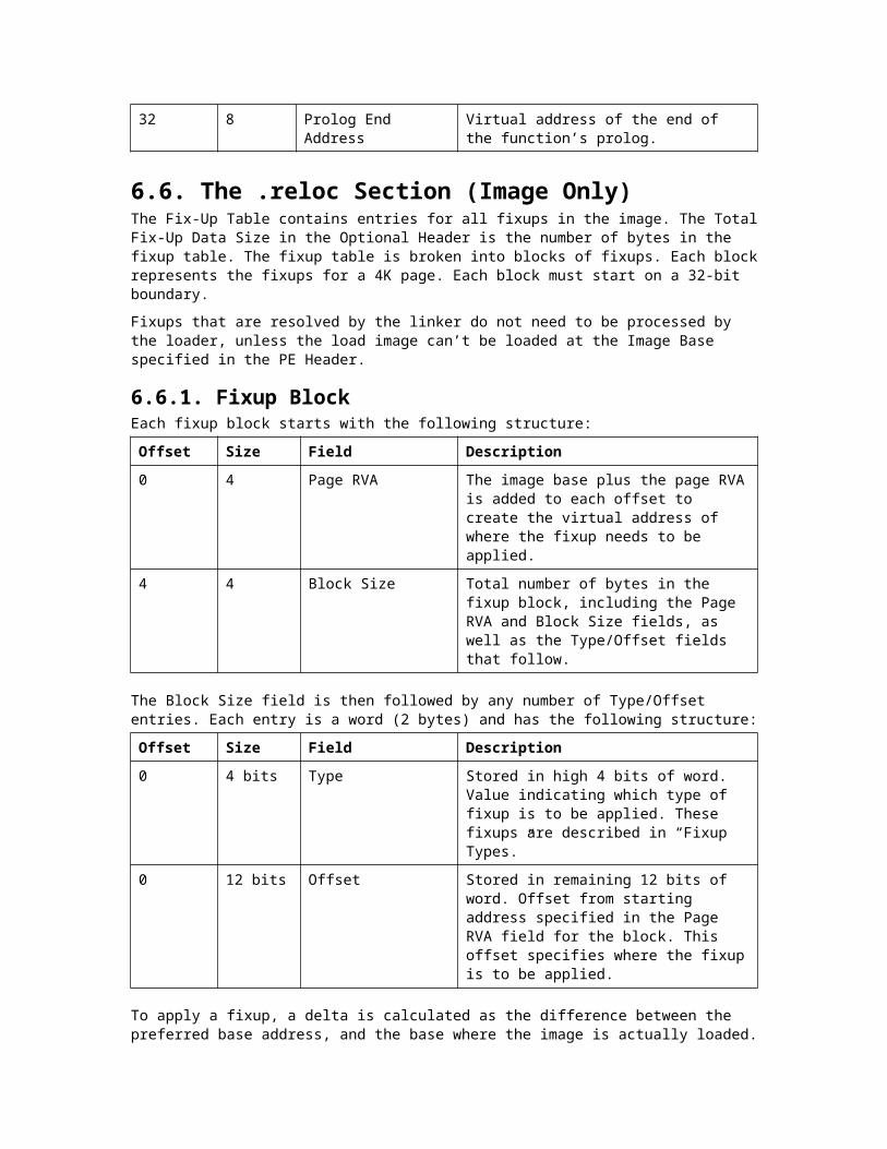
Header
Contents of OBJ File 1
(COFF format)
Header
Contents of OBJ File 2
(COFF format)
.
Header
Contents of OBJ File N
(COFF format)
Figure 4. Archive File Structure
7.1. Archive File SignatureThe archive file signature identifies the file type. Any utility (for example, a linker) expecting an archive file as input can check the file type by reading this signature. The signature consists of the following ASCII characters, in which each character below is represented literally, except for the newline (\n) character:S!<arch>\n
7.2. Archive Member HeadersEach member (linker, longnames, or object-file member) is preceded by a header. An archive member header has the following format, in which each field is an ASCII text string that is left justified and padded with spaces to the end of the field. There is no terminating null character in any of these fields.
Each member header starts on the first even address after the end of the previous archive member.
Offset Size Field Description
0 16 Name Name of archive member, with a slash (/) appended to terminate the name. If the first character is a slash, the name has a special interpretation, as described below.

16 12 Date Date and time the archive member was created: ASCII decimal representation of the number of seconds since 1/1/1970 UCT.
28 6 User ID ASCII decimal representation of the user ID.
34 6 Group ID ASCII group representation of the group ID.
40 8 Mode ASCII octal representation of the member’s file mode.
48 10 Size ASCII decimal representation of the total size of the archive member, not including the size of the header.
58 2 End of Header The two bytes in the C string “‘\n”.
The Name field has one of the formats shown in the following table. As mentioned above, each of these strings is left justified and padded with trailing spaces within a field of 16 bytes:
Contents of Name Field Description
Name/ The field gives the name of the archive member directly.
/ The archive member is one of the two linker members. Both of the linker members have this name.
// The archive member is the longname member, which consists of a series of null-terminated ASCII strings. The longnames member is the third archive member, and must always be present even if the contents are empty.
The name of the archive member is located at offset n within the longnames member. The number n is the decimal representation of the offset. For example: “\26” indicates that the name of the archive member is located 26 bytes beyond the beginning of longnames member contents.
7.3. First Linker MemberThe name of the first linker member is “\”. The first linker member, which is included for backward compatibility, is not used by current linkers but its format must be correct. This linker member provides a directory of symbol names, as does the second linker member. For each symbol, the information indicates where to find the archive member that contains the symbol.
The first linker member has the following format. This information appears after the header:
Offset Size Field Description
0 4 Number of Symbols Unsigned long containing the number of symbols indexed. This number is stored in big-endian format. Each object-file member typically defines one or more external symbols.

4 4 * n Offsets Array of file offsets to archive member headers, in which n is equal to Number of Symbols. Each number in the array is an unsigned long stored in big-endian format. For each symbol named in the String Table, the corresponding element in the Offsets array gives the location of the archive member that contains the symbol.
* * String Table Series of null-terminated strings that name all the symbols in the directory. Each string begins immediately after the null character in the previous string. The number of strings must be equal to the value of the Number of Symbols fields.
The elements in the Offsets array must be arranged in ascending order. This fact implies that the symbols listed in the String Table must be arranged according to the order of archive members. For example, all the symbols in the first object-file member would have to be listed before the symbols in the second object file.
7.4. Second Linker MemberThe second linker member has the name “\” as does the first linker member. Although both the linker members provide a directory of symbols and archive members that contain them, the second linker member is used in preference to the first by all current linkers. The second linker member includes symbol names in lexical order, which enables faster searching by name.
The first second member has the following format. This information appears after the header:
Offset Size Field Description
0 4 Number of Members Unsigned long containing the number of archive members.
4 4 * m Offsets Array of file offsets to archive member headers, arranged in ascending order. Each offset is an unsigned long. The number m is equal to the value of the Number of Members field.
* 4 Number of Symbols Unsigned long containing the number of symbols indexed. Each object-file member typically defines one or more external symbols.

* 2 * n Indices Array of 1-based indices (unsigned short) which map symbol names to archive member offsets. The number n is equal to Number of Symbols. For each symbol named in the String Table, the corresponding element in the Indices array gives an index into the Offsets array. The Offsets array, in turn, gives the location of the archive member that contains the symbol.
* * String Table Series of null-terminated strings that name all the symbols in the directory. Each string begins immediately after the null byte in the previous string. The number of strings must be equal to the value of the Number of Symbols fields. This table lists all the symbol names in ascending lexical order.
7.5. Longnames MemberThe name of the longnames member is “\\”. The longnames member is a series of strings of archive member names. A name appears here only when there is insufficient room in the Name field (16 bytes). The longnames member can be empty, though its header must appear.
The strings are null-terminated. Each string begins immediately after the null byte in the previous string.
8. Import Library FormatTraditional import libraries, i.e., libraries that describe the exports from one image for use by another, typically follow the layout described in 7. Archive (Library) File Format. The primary difference is that import library members contain pseudo-object files instead of real ones, where each member includes the section contributions needed to build the Import Tables described in Section 6.4 The .idata Section. The linker generates this archive while building the exporting application.
The section contributions for an import can be inferred from a small set of information. The linker can either generate the complete, verbose information into the import library for each member at the time of the library’s creation, or it can write only the canonical information to the library and let the application that later uses it generate the necessary data on-the-fly.
In an import library with the long format, a single member contains the following information:
Archive member headerFile headerSection headersData corresponding to each of the section headersCOFF symbol tableStrings
In contrast a short import library is written as follows:

Archive member headerImport headerNull-terminated import name stringNull-terminated DLL name string
This is sufficient information to accurately reconstruct the entire contents of the member at the time of its use.
8.1. Import HeaderThe import header contains the following fields and offsets:
Offset Size Field Description
0 2 Sig1 Must be IMAGE_FILE_MACHINE_UNKNOWN. See Section 3.3.1, “Machine Types, ” for more information.
2 2 Sig2 Must be 0xFFFF.
4 2 Version
6 2 Machine Number identifying type of target machine. See Section 3.3.1, “Machine Types, ” for more information.
8 4 Time-Date Stamp Time and date the file was created.
12 4 Size Of Data Size of the strings following the header.
16 2 Ordinal/Hint Either the ordinal or the hint for the import, determined by the value in the Name Type field.
18 2 bits Type The import type. See Section 8.2 Import Type for specific values and descriptions.
3 bits Name Type The Import Name Type. See Section 8.3. Import Name Type for specific values and descriptions.
11 bits Reserved Reserved. Must be zero.
This structure is followed by two null-terminated strings describing the imported symbol’s name, and the DLL from which it came.
8.2. Import TypeThe following values are defined for the Type field in the Import Header:
Constant Value Description
IMPORT_CODE 0 The import is executable code.
IMPORT_DATA 1 The import is data.

IMPORT_CONST 2 The import was specified as CONST in the .def file.
These values are used to determine which section contributions must be generated by the tool using the library if it must access that data.
8.3. Import Name TypeThe null-terminated import symbol name immediately follows its associated Import Header. The following values are defined for the Name Type field in the Import Header, indicating how the name is to be used to generate the correct symbols representing the import:
Constant Value Description
IMPORT_ORDINAL 0 The import is by ordinal. This indicates that the value in the Ordinal/Hint field of the Import Header is the import’s ordinal. If this constant is not specified, then the Ordinal/Hint field should always be interpreted as the import’s hint.
IMPORT_NAME 1 The import name is identical to the public symbol name.
IMPORT_NAME_NOPREFIX 2 The import name is the public symbol name, but skipping the leading ?, @, or optionally _.
IMPORT_NAME_UNDECORATE 3 The import name is the public symbol name, but skipping the leading ?, @, or optionally _, and truncating at the first @.
Appendix: Example Object FileThis section describes the PE/COFF object file produced by compiling the file HELLO2.C, which contains the following small C program:main(){foo();}
foo(){}
The commands used to compile HELLO.C (with debug information) and generate this example were the following (the -Gy option to the compiler is used, which causes each procedure to be generated as a separate COMDAT section):cl -c -Zi -Gy hello2.clink -dump -all hello2.obj >hello2.dmp
Here is the resulting file HELLO2.DMP: (The reader is encouraged to experiment with various other examples, in order to clarify the concepts described in this specification.)Dump of file hello2.obj
File Type: COFF OBJECT
FILE HEADER VALUES
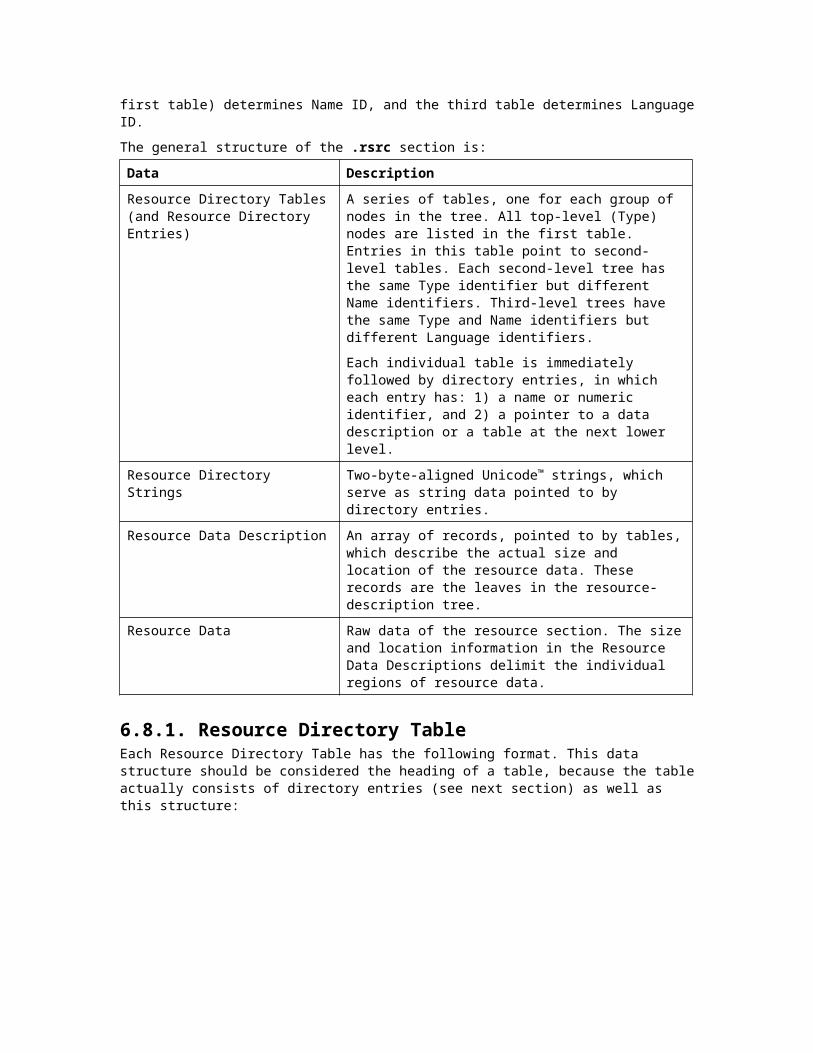
14C machine (i386) 7 number of sections3436E157 time date stamp Sat Oct 04 17:37:43 1997 2A0 file pointer to symbol table 1E number of symbols 0 size of optional header 0 characteristics
SECTION HEADER #1.drectve name 0 physical address 0 virtual address 26 size of raw data 12C file pointer to raw data 0 file pointer to relocation table 0 file pointer to line numbers 0 number of relocations 0 number of line numbers 100A00 flags Info Remove 1 byte align
RAW DATA #100000000 2D 64 65 66 61 75 6C 74 | 6C 69 62 3A 4C 49 42 43 -default|lib:LIBC00000010 20 2D 64 65 66 61 75 6C | 74 6C 69 62 3A 4F 4C 44 -defaul|tlib:OLD00000020 4E 41 4D 45 53 20 NAMES
Linker Directives ----------------- -defaultlib:LIBC -defaultlib:OLDNAMES
SECTION HEADER #2.debug$S name 0 physical address 0 virtual address 5C size of raw data 152 file pointer to raw data 0 file pointer to relocation table 0 file pointer to line numbers 0 number of relocations 0 number of line numbers42100048 flags No Pad Initialized Data Discardable 1 byte align Read Only
RAW DATA #200000000 02 00 00 00 11 00 09 00 | 00 00 00 00 0A 68 65 6C ........|.....hel00000010 6C 6F 32 2E 6F 62 6A 43 | 00 01 00 05 00 00 00 3C lo2.objC|.......<00000020 4D 69 63 72 6F 73 6F 66 | 74 20 28 52 29 20 33 32 Microsof|t (R) 3200000030 2D 62 69 74 20 43 2F 43 | 2B 2B 20 4F 70 74 69 6D -bit C/C|++ Optim00000040 69 7A 69 6E 67 20 43 6F | 6D 70 69 6C 65 72 20 56 izing Co|mpiler V00000050 65 72 73 69 6F 6E 20 31 | 31 2E 30 30 ersion 1|1.00
SECTION HEADER #3 .text name 0 physical address 0 virtual address A size of raw data 1AE file pointer to raw data 1B8 file pointer to relocation table 1C2 file pointer to line numbers 1 number of relocations 3 number of line numbers60501020 flags Code Communal; sym= _main 16 byte align

Execute Read
RAW DATA #300000000 55 8B EC E8 00 00 00 00 | 5D C3 U‹ìè....|].
RELOCATIONS #3 Symbol Symbol Offset Type Applied To Index Name -------- ---------------- ----------------- -------- ------ 00000004 REL32 00000000 13 _foo
LINENUMBERS #3
Symbol index: 8 Base line number: 2 Symbol name = _main 00000003( 3) 00000008( 4)
SECTION HEADER #4.debug$S name 0 physical address 0 virtual address 30 size of raw data 1D4 file pointer to raw data 204 file pointer to relocation table 0 file pointer to line numbers 2 number of relocations 0 number of line numbers42101048 flags No Pad Initialized Data Communal (no symbol) Discardable 1 byte align Read Only
RAW DATA #400000000 2A 00 0B 10 00 00 00 00 | 00 00 00 00 00 00 00 00 *.......|........00000010 0A 00 00 00 03 00 00 00 | 08 00 00 00 01 10 00 00 ........|........00000020 00 00 00 00 00 00 01 04 | 6D 61 69 6E 02 00 06 00 ........|main....
RELOCATIONS #4 Symbol Symbol Offset Type Applied To Index Name -------- ---------------- ----------------- -------- ------ 00000020 SECREL 00000000 8 _main 00000024 SECTION 0000 8 _main
SECTION HEADER #5 .text name 0 physical address 0 virtual address 5 size of raw data 218 file pointer to raw data 0 file pointer to relocation table 21D file pointer to line numbers 0 number of relocations 2 number of line numbers60501020 flags Code Communal; sym= _foo 16 byte align Execute Read
RAW DATA #500000000 55 8B EC 5D C3 U‹ì].
LINENUMBERS #5
Symbol index: 13 Base line number: 7 Symbol name = _foo 00000003( 8)

SECTION HEADER #6.debug$S name 0 physical address 0 virtual address 2F size of raw data 229 file pointer to raw data 258 file pointer to relocation table 0 file pointer to line numbers 2 number of relocations 0 number of line numbers42101048 flags No Pad Initialized Data Communal (no symbol) Discardable 1 byte align Read Only
RAW DATA #600000000 29 00 0B 10 00 00 00 00 | 00 00 00 00 00 00 00 00 ).......|........00000010 05 00 00 00 03 00 00 00 | 03 00 00 00 01 10 00 00 ........|........00000020 00 00 00 00 00 00 01 03 | 66 6F 6F 02 00 06 00 ........|foo....
RELOCATIONS #6 Symbol Symbol Offset Type Applied To Index Name -------- ---------------- ----------------- -------- ------ 00000020 SECREL 00000000 13 _foo 00000024 SECTION 0000 13 _foo
SECTION HEADER #7.debug$T name 0 physical address 0 virtual address 34 size of raw data 26C file pointer to raw data 0 file pointer to relocation table 0 file pointer to line numbers 0 number of relocations 0 number of line numbers42100048 flags No Pad Initialized Data Discardable 1 byte align Read Only
RAW DATA #700000000 02 00 00 00 2E 00 16 00 | 33 E1 36 34 01 00 00 00 ........|3á64....00000010 22 65 3A 5C 62 62 74 5C | 74 6F 6F 6C 73 5C 76 63 "e:\bbt\|tools\vc00000020 35 30 5C 62 69 6E 5C 78 | 38 36 5C 76 63 35 30 2E 50\bin\x|86\vc50.00000030 70 64 62 F1 pdb.
COFF SYMBOL TABLE000 00000000 DEBUG notype Filename | .file hello2.c002 00000000 SECT1 notype Static | .drectve Section length 26, #relocs 0, #linenums 0, checksum 0004 00000000 SECT2 notype Static | .debug$S Section length 5C, #relocs 0, #linenums 0, checksum 0006 00000000 SECT3 notype Static | .text Section length A, #relocs 1, #linenums 3, checksum 0, selection 1 (pick no duplicates)008 00000000 SECT3 notype () External | _main tag index 0000000A size 0000000A lines 000001C2 next function 0000001300A 00000000 SECT3 notype BeginFunction | .bf line# 0002 end 0000001500C 00000003 SECT3 notype .bf or.ef | .lf00D 0000000A SECT3 notype EndFunction | .ef line# 000400F 00000000 SECT4 notype Static | .debug$S
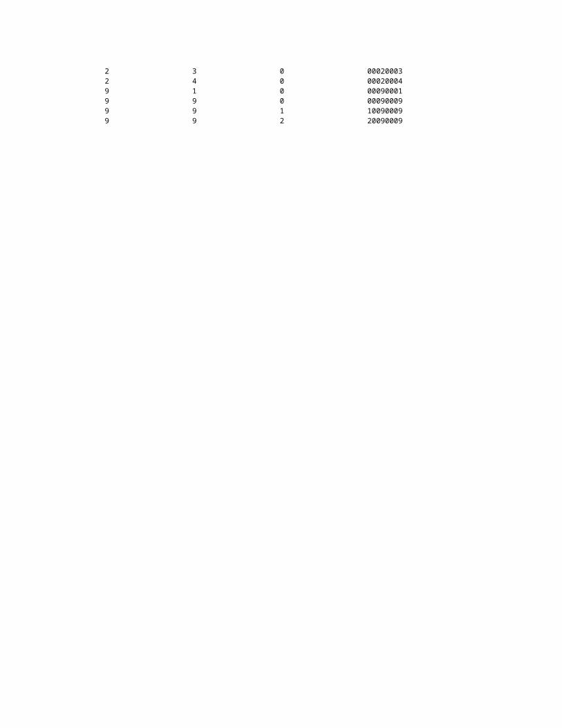
Section length 30, #relocs 2, #linenums 0, checksum 0, selection 5 (pick associative Section 3)011 00000000 SECT5 notype Static | .text Section length 5, #relocs 0, #linenums 2, checksum 0, selection 1 (pick no duplicates)013 00000000 SECT5 notype () External | _foo tag index 00000015 size 00000005 lines 0000021D next function 00000000015 00000000 SECT5 notype BeginFunction | .bf line# 0007 end 00000000017 00000002 SECT5 notype .bf or.ef | .lf018 00000005 SECT5 notype EndFunction | .ef line# 000801A 00000000 SECT6 notype Static | .debug$S Section length 2F, #relocs 2, #linenums 0, checksum 0, selection 5 (pick associative Section 5)01C 00000000 SECT7 notype Static | .debug$T Section length 34, #relocs 0, #linenums 0, checksum 0
String Table Size = 0x0 bytes
Summary
BB .debug$S 34 .debug$T 26 .drectve F .text
Here is a hexadecimal dump of HELLO2.OBJ:hello2.obj: 00000000 4c 01 07 00 57 e1 36 34 a0 02 00 00 1e 00 00 00 L...W.64........00000010 00 00 00 00 2e 64 72 65 63 74 76 65 00 00 00 00 .....drectve....00000020 00 00 00 00 26 00 00 00 2c 01 00 00 00 00 00 00 ....&...,.......00000030 00 00 00 00 00 00 00 00 00 0a 10 00 2e 64 65 62 .............deb00000040 75 67 24 53 00 00 00 00 00 00 00 00 5c 00 00 00 ug$S........\...00000050 52 01 00 00 00 00 00 00 00 00 00 00 00 00 00 00 R...............00000060 48 00 10 42 2e 74 65 78 74 00 00 00 00 00 00 00 H..B.text.......00000070 00 00 00 00 0a 00 00 00 ae 01 00 00 b8 01 00 00 ................00000080 c2 01 00 00 01 00 03 00 20 10 50 60 2e 64 65 62 ........ .P`.deb00000090 75 67 24 53 00 00 00 00 00 00 00 00 30 00 00 00 ug$S........0...000000a0 d4 01 00 00 04 02 00 00 00 00 00 00 02 00 00 00 ................000000b0 48 10 10 42 2e 74 65 78 74 00 00 00 00 00 00 00 H..B.text.......000000c0 00 00 00 00 05 00 00 00 18 02 00 00 00 00 00 00 ................000000d0 1d 02 00 00 00 00 02 00 20 10 50 60 2e 64 65 62 ........ .P`.deb000000e0 75 67 24 53 00 00 00 00 00 00 00 00 2f 00 00 00 ug$S......../...000000f0 29 02 00 00 58 02 00 00 00 00 00 00 02 00 00 00 )...X...........00000100 48 10 10 42 2e 64 65 62 75 67 24 54 00 00 00 00 H..B.debug$T....00000110 00 00 00 00 34 00 00 00 6c 02 00 00 00 00 00 00 ....4...l.......00000120 00 00 00 00 00 00 00 00 48 00 10 42 2d 64 65 66 ........H..B-def00000130 61 75 6c 74 6c 69 62 3a 4c 49 42 43 20 2d 64 65 aultlib:LIBC -de00000140 66 61 75 6c 74 6c 69 62 3a 4f 4c 44 4e 41 4d 45 faultlib:OLDNAME00000150 53 20 02 00 00 00 11 00 09 00 00 00 00 00 0a 68 S .............h00000160 65 6c 6c 6f 32 2e 6f 62 6a 43 00 01 00 05 00 00 ello2.objC......00000170 00 3c 4d 69 63 72 6f 73 6f 66 74 20 28 52 29 20 .<Microsoft (R) 00000180 33 32 2d 62 69 74 20 43 2f 43 2b 2b 20 4f 70 74 32-bit C/C++ Opt00000190 69 6d 69 7a 69 6e 67 20 43 6f 6d 70 69 6c 65 72 imizing Compiler000001a0 20 56 65 72 73 69 6f 6e 20 31 31 2e 30 30 55 8b Version 11.00U.000001b0 ec e8 00 00 00 00 5d c3 04 00 00 00 13 00 00 00 ......].........000001c0 14 00 08 00 00 00 00 00 03 00 00 00 01 00 08 00 ................000001d0 00 00 02 00 2a 00 0b 10 00 00 00 00 00 00 00 00 ....*...........000001e0 00 00 00 00 0a 00 00 00 03 00 00 00 08 00 00 00 ................000001f0 01 10 00 00 00 00 00 00 00 00 01 04 6d 61 69 6e ............main00000200 02 00 06 00 20 00 00 00 08 00 00 00 0b 00 24 00 .... .........$.00000210 00 00 08 00 00 00 0a 00 55 8b ec 5d c3 13 00 00 ........U..]....00000220 00 00 00 03 00 00 00 01 00 29 00 0b 10 00 00 00 .........)......00000230 00 00 00 00 00 00 00 00 00 05 00 00 00 03 00 00 ................00000240 00 03 00 00 00 01 10 00 00 00 00 00 00 00 00 01 ................00000250 03 66 6f 6f 02 00 06 00 20 00 00 00 13 00 00 00 .foo.... .......00000260 0b 00 24 00 00 00 13 00 00 00 0a 00 02 00 00 00 ..$.............00000270 2e 00 16 00 33 e1 36 34 01 00 00 00 22 65 3a 5c ....3.64...."e:\00000280 62 62 74 5c 74 6f 6f 6c 73 5c 76 63 35 30 5c 62 bbt\tools\vc50\b00000290 69 6e 5c 78 38 36 5c 76 63 35 30 2e 70 64 62 f1 in\x86\vc50.pdb.

000002a0 2e 66 69 6c 65 00 00 00 00 00 00 00 fe ff 00 00 .file...........000002b0 67 01 68 65 6c 6c 6f 32 2e 63 00 00 00 00 00 00 g.hello2.c......000002c0 00 00 00 00 2e 64 72 65 63 74 76 65 00 00 00 00 .....drectve....000002d0 01 00 00 00 03 01 26 00 00 00 00 00 00 00 00 00 ......&.........000002e0 00 00 00 00 00 00 00 00 2e 64 65 62 75 67 24 53 .........debug$S000002f0 00 00 00 00 02 00 00 00 03 01 5c 00 00 00 00 00 ..........\.....00000300 00 00 00 00 00 00 00 00 00 00 00 00 2e 74 65 78 .............tex00000310 74 00 00 00 00 00 00 00 03 00 00 00 03 01 0a 00 t...............00000320 00 00 01 00 03 00 00 00 00 00 00 00 01 00 00 00 ................00000330 5f 6d 61 69 6e 00 00 00 00 00 00 00 03 00 20 00 _main......... .00000340 02 01 0a 00 00 00 0a 00 00 00 c2 01 00 00 13 00 ................00000350 00 00 00 00 2e 62 66 00 00 00 00 00 00 00 00 00 .....bf.........00000360 03 00 00 00 65 01 00 00 00 00 02 00 00 00 00 00 ....e...........00000370 00 00 15 00 00 00 00 00 2e 6c 66 00 00 00 00 00 .........lf.....00000380 03 00 00 00 03 00 00 00 65 00 2e 65 66 00 00 00 ........e..ef...00000390 00 00 0a 00 00 00 03 00 00 00 65 01 00 00 00 00 ..........e.....000003a0 04 00 00 00 00 00 00 00 00 00 00 00 00 00 2e 64 ...............d000003b0 65 62 75 67 24 53 00 00 00 00 04 00 00 00 03 01 ebug$S..........000003c0 30 00 00 00 02 00 00 00 00 00 00 00 03 00 05 00 0...............000003d0 00 00 2e 74 65 78 74 00 00 00 00 00 00 00 05 00 ...text.........000003e0 00 00 03 01 05 00 00 00 00 00 02 00 00 00 00 00 ................000003f0 00 00 01 00 00 00 5f 66 6f 6f 00 00 00 00 00 00 ......_foo......00000400 00 00 05 00 20 00 02 01 15 00 00 00 05 00 00 00 .... ...........00000410 1d 02 00 00 00 00 00 00 00 00 2e 62 66 00 00 00 ...........bf...00000420 00 00 00 00 00 00 05 00 00 00 65 01 00 00 00 00 ..........e.....00000430 07 00 00 00 00 00 00 00 00 00 00 00 00 00 2e 6c ...............l00000440 66 00 00 00 00 00 02 00 00 00 05 00 00 00 65 00 f.............e.00000450 2e 65 66 00 00 00 00 00 05 00 00 00 05 00 00 00 .ef.............00000460 65 01 00 00 00 00 08 00 00 00 00 00 00 00 00 00 e...............00000470 00 00 00 00 2e 64 65 62 75 67 24 53 00 00 00 00 .....debug$S....00000480 06 00 00 00 03 01 2f 00 00 00 02 00 00 00 00 00 ....../.........00000490 00 00 05 00 05 00 00 00 2e 64 65 62 75 67 24 54 .........debug$T000004a0 00 00 00 00 07 00 00 00 03 01 34 00 00 00 00 00 ..........4.....000004b0 00 00 00 00 00 00 00 00 00 00 00 00 04 00 00 00 ................
Appendix: Calculating Image Message DigestsSeveral Attribute Certificates are expected to be used to verify the integrity of the images. That is, they will be used to ensure that a particular image file, or part of that image file, has not been altered in any way from its original form. To accomplish this task, these certificates will typically include something called a Message Digest.
Message digests are similar to a file checksum in that they produce a small value that relates to the integrity of a file. A checksum is produced by a simple algorithm and its use is primarily to detect memory failures. That is, it is used to detect whether or not a block of memory on disk has gone bad and the values stored there have become corrupted. A message digest is similar to a checksum in that it will also detect file corruption. However, unlike most checksum algorithms, a message digest also has the property that it is very difficult to modify a file such that it will have the same message digest as its original (unmodified) form. That is, a checksum is intended to detect simple memory failures leading to corruption, but a message digest may be used to detect intentional, and even crafty modifications to a file, such as those introduced by viruses, hackers, or Trojan Horse programs.
It is not desirable to include all image file data in the calculation of a message digest. In some cases it simply presents undesirable characteristics (like the file is no longer localizable without regenerating certificates) and in other cases it is simply impossible. For example, it is not possible to include all information within an image file in a message digest, then insert a certificate containing that message digest in the file, and later be able to generate an identical message digest by including all image file data in the calculation again (since the file now contains a certificate that wasn’t originally there).

This specification does not attempt to architect what each Attribute Certificate may be used for, or which fields or sections of an image file must be included in a message digest. However, this section does identify which fields you may not want to or may not include in a message digest.
In addition to knowing which fields are and are not included in the calculation of a message digest, it is important to know the order in which the contents of the image are presented to the digest algorithm. This section specifies that order.
Fields Not To Include In DigestsThere are some parts of an image that you may not want to include in any message digest. This section identifies those parts, and describes why you might not want to include them in a message digest.
1. Information related to Attribute Certificates - It is not possible to include a certificate in the calculation of a message digest that resides within the certificate. Since certificates can be added to or removed from an image without effecting the overall integrity of the image this is not a problem. Therefore, it is best to leave all attribute certificates out of the image even if there are certificates already in the image at the time you are calculating your message digest. There is no guarantee those certificates will still be there later, or that other certificates won’t have been added. To exclude attribute certificate information from the message digest calculation, you must exclude the following information from that calculation:
The Certificate Table field of the Optional Header Data Directories.
The Certificate Table and corresponding certificates pointed to by the Certificate Table field listed immediately above.
2. Debug information - Debug information may generally be considered advisory (to debuggers) and does not effect the actual integrity of the executable program. It is quite literally possible to remove debug information from an image after a product has been delivered and not effect the functionality of the program. This is, in fact, a disk saving measure that is sometimes utilized. If you do not want to include debug information in your message digest, then you should not include the following information in your message digest calculation:
The Debug entry of the Data Directory in with optional header.
The .debug section
3. File Checksum field of the Windows NT-Specific Fields of the Optional Header - This checksum includes the entire file (including any attribute certificates included in the file) and will, in all likelihood, be different after inserting your certificate than when you were originally calculating a message digest to include in your certificate.
4. Unused, or obsolete fields - There are several fields that are either unused or obsolete. The value of these fields is undefined and may change after you calculate your message digest. These fields include:
Reserved field of the Optional Header Windows NT-Specific Fields (offset 52).
The DLL Flags field of the Optional Header Windows NT-Specific Fields. This field is obsolete.
Loader Flags field of the Optional Header Windows NT-Specific Fields. This field is obsolete.
Reserved entries of the Data Directory in the object header.

5. Resources (makes localization easier) - depending upon the specifics of your Attribute Certificate, it may be desirable or undesirable to include resources in the message digest. If you want to allow localization without the generation of new certificates, then you do not want to include resources in your message digest. If the values of the resources are critical to your application, then you probably do want them included in your message digest, and you will accept the overhead of generating a certificate for each localized copy of the image. If you do not want to include resources in your message digest, then you should not include the following information in the message digest calculation:
Resource Table entry of the Optional Header Data Directory.
The .rsrc section.