poolpak™ r410a mpk series -...
TRANSCRIPT

TMTM
POOLPAK™ R410AMPK SERIES
MS (Supply Fan and Outside Air)MSE (Supply Fan, Exhaust Fan, and Outside Air)
MSEP (Supply Fan, Exhaust Fan, Purge Fan, and Outside Air)
Engineering GuideEGW07-MPKEG-20150126
Packaged Natatorium Environment Control System
PENDING
PoolPakTM MPK Series (MSEP with Integral ACC shown above) Natatorium Dehumidification Unit
TMTM

TMTM
TMTM
3491 Industrial Drive . York, PA 17402 . USA . 800-959-7725 . Fax 717-757-5085for more information: www.poolpak.com
The Leader in Indoor Pool Dehumidification

IEGW07-MPKEG-20150126
TMTM
Table of ContentsSECTION I: INDOOR POOL DESIGN
Introduction ..................................................................................................................................................................................1Creating an ideal environment for indoor pool facilities............................................................................................................ 1Operating Cost ......................................................................................................................................................................... 1
Application ................................................................................................................................................................................... 1Moisture Loads ........................................................................................................................................................................ 1Effects of Moisture ................................................................................................................................................................... 1Indoor Air Quality ...................................................................................................................................................................... 1Occupant Comfort .................................................................................................................................................................... 2Pool Water Chemistry ............................................................................................................................................................. 2
Equipment Choices ...................................................................................................................................................................... 3Overview ................................................................................................................................................................................. 3Ventilation with Heating ............................................................................................................................................................ 3Ventilation with Heating and Energy Recovery ........................................................................................................................ 3Mechanical Dehumidification.................................................................................................................................................... 3Hybrids .....................................................................................................................................................................................3Other Technologies .................................................................................................................................................................. 4
Room Air Distribution ................................................................................................................................................................... 4Air-side Design ......................................................................................................................................................................... 4
Supply Air.............................................................................................................................................................................. 4Return Air .............................................................................................................................................................................. 5Ductwork Design................................................................................................................................................................... 5Air Distribution ...................................................................................................................................................................... 5Air Connections to PoolPak™ .............................................................................................................................................. 6Other Air-side Considerations ............................................................................................................................................... 6
Duct Design for Accurate Airflow Measurement ....................................................................................................................... 7
SECTION II: POOLPAK PRINCIPLES, FUNCTIONS, AND FEATURESThe Mechanical Dehumidification System ................................................................................................................................... 8
Principles of Operation ............................................................................................................................................................. 8Automatic Control of Air Temperature and Humidity ................................................................................................................ 8Room Dew Point Control .......................................................................................................................................................... 9PoolPak Operation ................................................................................................................................................................... 10
Refrigerant-Side Operation ................................................................................................................................................... 10Air-Side Operation ................................................................................................................................................................ 10
ICC Control Functions.................................................................................................................................................................. 12Overview .................................................................................................................................................................................. 12Air Flow Monitoring and Control ............................................................................................................................................... 12Humidity Control ....................................................................................................................................................................... 13Cold Surface Temperature Humidity Reset .............................................................................................................................. 14Space Heating .......................................................................................................................................................................... 14Smart Economizer (MSEP) ...................................................................................................................................................... 14Flywheel Air Conditioning (MSEP) ........................................................................................................................................... 14Space Cooling (Optional) ......................................................................................................................................................... 14
Air Conditioning with Air-Cooled Condenser......................................................................................................................... 15Air Conditioning with Water-Cooled Condenser ................................................................................................................... 15Air Conditioning with Chilled Water Coil ............................................................................................................................... 15
Pool Water Heating .................................................................................................................................................................. 15Smart Pump Control™ (Optional) ............................................................................................................................................ 15Networking Multiple Units ......................................................................................................................................................... 15Occupied/Unoccupied Control Mode........................................................................................................................................ 15Purge Mode (MSEP) ................................................................................................................................................................ 16Event Mode (MSEP)................................................................................................................................................................. 16Summer Ventilation Mode (MSEP)........................................................................................................................................... 16CO2 Based Demand Ventilation (Optional) .............................................................................................................................. 16
Features and Options .................................................................................................................................................................. 17Standard Factory Mounted Features........................................................................................................................................ 17Standard Factory Supplied, Field Installed Features ............................................................................................................... 17Optional Factory Mounted Features ......................................................................................................................................... 17Optional Field Installed Features.............................................................................................................................................. 17Selection................................................................................................................................................................................... 18

II EGW07-MPKEG-20150126
TMTM
SECTION III: SIZING AND PERFORMANCEPoolPak Unit Dimensions and Weights .................................................................................................................................... 19MPK Performance Summary.................................................................................................................................................... 20MPK Factory Charge ................................................................................................................................................................ 20PoolPak Provided Remote ACC Specifications........................................................................................................................ 21Remote Air Conditioning Condenser Selection Guide.............................................................................................................. 22Non-PoolPak-Provided Air-Cooled Condenser Selection Procedure ....................................................................................... 22Remote Cooling Tower Condenser Sizing and Performance ................................................................................................... 22Water Cooled Condenser Sizing and Performance ................................................................................................................. 23PoolPak Pool Water Condenser ............................................................................................................................................... 24PoolPak Auxiliary Gas Furnace Option .................................................................................................................................... 25PoolPak Auxiliary Electric Heat Option..................................................................................................................................... 25
SECTION IV: INSTALLATIONMPK Installation ........................................................................................................................................................................... 26
Introduction............................................................................................................................................................................... 26Handling ................................................................................................................................................................................... 27Rigging .....................................................................................................................................................................................27Clearance ................................................................................................................................................................................. 27Duct Installation ........................................................................................................................................................................ 27Mounting................................................................................................................................................................................... 27Foundation ............................................................................................................................................................................... 28Inspection ................................................................................................................................................................................. 28Unit Hookup.............................................................................................................................................................................. 28
Gas Furnace Auxiliary Heat Option ...................................................................................................................................... 28Power Supply........................................................................................................................................................................ 28Control Wiring ....................................................................................................................................................................... 29Condensate Piping ............................................................................................................................................................... 29Curb Mounting ...................................................................................................................................................................... 30
ICC Controls Field Wiring ............................................................................................................................................................ 30Overview .................................................................................................................................................................................. 30Remote Interface Unit (1) ......................................................................................................................................................... 30Multi-unit Network Connection (2) ............................................................................................................................................ 32Building Automation System Connection (3) ............................................................................................................................ 32Cold Surface Temperature Sensor (4) ...................................................................................................................................... 32Supply Air Temperature Sensor (5) .......................................................................................................................................... 32Remote Space Pressure Sensor (Optional) (6)........................................................................................................................ 32ACC or WCC Proof Interlock (7) .............................................................................................................................................. 33Freezestat (8) (Special applications only) ............................................................................................................................... 33Remote Exhaust Fan Status (9) ............................................................................................................................................... 33Summer Ventilation Mode (MSE/MSEP only) (10) ................................................................................................................... 33Event Mode Interlock (11) ........................................................................................................................................................ 33Purge Mode Input (MSEP only)(12) ......................................................................................................................................... 33Occupied Mode Input (13) ........................................................................................................................................................ 34Fire Trip Input (14) .................................................................................................................................................................... 34Smoke Purge Input (MSE/MSEP only) (15) ............................................................................................................................ 34Auxiliary Chilled Water Control Valve (16)................................................................................................................................ 34Auxiliary Hot Water Control Valve (17) ..................................................................................................................................... 34Remote Air Cooled Condenser Enable Signal (18) .................................................................................................................. 34Smart Pump Control Output (19).............................................................................................................................................. 35Remote Exhaust Fan Interlock (MS only) (20) ......................................................................................................................... 35Auxiliary Pool Water Heating System (21) ............................................................................................................................... 35Alarm Output (22) ..................................................................................................................................................................... 35Auxiliary Air Cooling System (23) ............................................................................................................................................ 35Auxiliary Air Heating System (24) ............................................................................................................................................. 35Outside Air Temperature and Relative Humidity Sensor (25) ................................................................................................... 36
Pool Water Piping and Installation ............................................................................................................................................... 36PoolPak Pool Water Circulation Loop ...................................................................................................................................... 36Auxiliary Pool Water Heater (field supplied) ............................................................................................................................. 36Main Pool Water Pump and PoolPak Pool Water Loop Pump Interlocks ................................................................................. 37Pool Water Isolation Valves ...................................................................................................................................................... 37Pool Water Pressure Transducer ............................................................................................................................................. 37Pool Water Piping Composition ................................................................................................................................................ 37

IIIEGW07-MPKEG-20150126
TMTM
Freeze Protection ..................................................................................................................................................................... 37Condensate Drains ...................................................................................................................................................................... 38
Condensate Drainage System Features .................................................................................................................................. 38Exceptions ................................................................................................................................................................................ 38Drain Trap Field Installation Instructions .................................................................................................................................. 38Required Materials ................................................................................................................................................................... 39
Remote AIR COOLED Condenser ............................................................................................................................................... 40Space and Location Requirements .......................................................................................................................................... 40
Walls or Obstructions ............................................................................................................................................................ 40Multiple Units ........................................................................................................................................................................ 41Units in Pits ........................................................................................................................................................................... 41Decorative Fences ................................................................................................................................................................ 41
Field Installed Piping ................................................................................................................................................................ 42Piping Guidelines .................................................................................................................................................................. 42
Materials: ........................................................................................................................................................................... 42Sizing: ............................................................................................................................................................................... 42Refrigerant and Oil Charging: ........................................................................................................................................... 44
SECTION V: OPERATIONICC Controller Operation ............................................................................................................................................................. 45
Remote Interface Unit (RIU) Features...................................................................................................................................... 45ICC Controller Features ........................................................................................................................................................... 46Controller Navigation ................................................................................................................................................................ 47Fault Condition ......................................................................................................................................................................... 47Alarm Reset.............................................................................................................................................................................. 48
Communications .......................................................................................................................................................................... 48Building Automation System (BAS) Connection ....................................................................................................................... 48Virtual-Tech™ Plus - Remote Access Package (RAP) ............................................................................................................. 48
Ethernet 10/100 Direct Connection....................................................................................................................................... 48Send Emails – Alerts for Alarms ........................................................................................................................................... 49
Airflow Balancing ......................................................................................................................................................................... 49Overview .................................................................................................................................................................................. 49Guidelines for Performing a Proper Airflow Balance ................................................................................................................ 49Controller Adjustments ............................................................................................................................................................. 49
Troubleshooting ........................................................................................................................................................................... 49Overview .................................................................................................................................................................................. 49System Status Information ....................................................................................................................................................... 49Fault History Log ...................................................................................................................................................................... 50Manual Mode............................................................................................................................................................................ 51Digital and Analog Input Information ........................................................................................................................................ 51
Digital Input ........................................................................................................................................................................... 51Analog Input.......................................................................................................................................................................... 51
Digital and Analog Output Configuration .................................................................................................................................. 51Digital Output ........................................................................................................................................................................ 51Analog Output ....................................................................................................................................................................... 51
STARTUP & WARRANTY ............................................................................................................................................................ 52Pre-Startup ............................................................................................................................................................................... 52Startup ......................................................................................................................................................................................52Owner Training ......................................................................................................................................................................... 53Warranty ................................................................................................................................................................................... 53
Maintenance ................................................................................................................................................................................ 54Overview .................................................................................................................................................................................. 54Daily Maintenance .................................................................................................................................................................... 54Monthly Maintenance ............................................................................................................................................................... 54Semi-Annual Maintenance ....................................................................................................................................................... 55Annual Maintenance................................................................................................................................................................. 55
SECTION VI: WIRINGRemote Connections Schematic .............................................................................................................................................. 57Multiple Unit Control Schematic ............................................................................................................................................... 58MPK Field WIring - communications ........................................................................................................................................ 58MPK Field Wiring ...................................................................................................................................................................... 59

IV EGW07-MPKEG-20150126
TMTM
List of TablesTable 1-1. Typical Pool Water & Air Temperature Set-Points ...................................................................................2Table 1-2. Recommended Pool Water Chemistry ....................................................................................................2Table 3-1. MPK Dimensions and Weights ................................................................................................................19Table 3-2. MPK Unit Performance ...........................................................................................................................20Table 3-3. MPK Factory Refrigerant Charge ............................................................................................................20Table 3-4. PoolPak™ Provided Remote ACC Specifications ...................................................................................21Table 3-5. Remote Cooling Tower and Chilled Water Cabinet Dimensions .............................................................23Table 3-6. Remote Cooling Tower and Chilled Water Line Sizes .............................................................................23Table 3-7. WCC Performance ..................................................................................................................................23Table 3-8. Pool Water Capacity ................................................................................................................................24Table 3-9. PoolPak™ Gas Furnace Option ..............................................................................................................25Table 3-10. PoolPak™ Electric Heat Option ............................................................................................................25Table 4-1. Pipe Sizes for Remote Refrigerant Condensers .....................................................................................43Table 4-2. Remote ACC Refrigerant (R-410A) Charge ............................................................................................44Table 4-3. Refrigerant (R-410A) Charge for Different Line Sizes .............................................................................44Table 5-1. Pool Water Chemistry ..............................................................................................................................54
List of FiguresFigure 1-1. Perimeter Air Distribution .......................................................................................................................4Figure 1-2. Overhead Air Distribution .......................................................................................................................5Figure 1-3. Below Grade Air Distribution ..................................................................................................................5Figure 1-4. Supply Air Proportions ...........................................................................................................................6Figure 2-1. Dewpoint Control Psychrometric ..........................................................................................................9Figure 2-2. MPK System Schematic ........................................................................................................................11Figure 2-3. Active Airflow Control with Direct OA Measurement Schematic ............................................................13Figure 3-1. MPK Dimensional Isometric View ..........................................................................................................19Figure 3-2. Remote Cooling Tower Dimensions .......................................................................................................22Figure 4-1. Typical PoolPak™ Rooftop Installation ..................................................................................................26Figure 4-2. Single Point Power Supply ....................................................................................................................29Figure 4-3. Dual Point Power Supply .......................................................................................................................29Figure 4-4. Remote Interface Mounting Plate ..........................................................................................................31Figure 4-5. Pool Water Piping Schematic ................................................................................................................38Figure 4-6. Negative Pressure Condensate Drain Piping Cross Section .................................................................39Figure 4-7. Positive Pressure Condensate Drain Piping Cross Section ..................................................................39Figure 4-8. Remote ACC Installation Around Walls or Obstructions ........................................................................40Figure 4-9. Remote ACC Installation When Installing Multiple Units .......................................................................41Figure 4-10. Remote ACC Installation When Installing Units in Pits ........................................................................41Figure 4-11. Remote ACC Installation When Installing Units Near Decorative Fences ...........................................41Figure 4-12. Remote ACC Above Unit .....................................................................................................................43Figure 5-1. RIU Keypad ...........................................................................................................................................45Figure 5-2. ICC Controller (CM1) Display ................................................................................................................46Figure 6-1. PoolPak™ Control Panel .......................................................................................................................57Figure 6-2. Multiple Unti Connection Schematic ......................................................................................................58Figure 6-3. Field Wiring - Communications ..............................................................................................................58Figure 6-4. Field Wiring Diagram .............................................................................................................................59

1EGW07-MPKEG-20150126
TMTM
SECTION I: INDOOR POOL DESIGNINTRODUCTIONCREATING AN IDEAL ENVIRONMENT FOR INDOOR POOL FACILITIES
Indoor pool facilities are unlike any other structure in design, construction and maintenance requirements. Humidity, air and water temperatures are especially difficult to control, and improper management usually results in an uncomfortable environment, excessive operating costs and possibly serious structural damage. Effectively controlling these special conditions requires control hardware and control sequences specially engineered for large commercial indoor pool applications. The PoolPak™ System utilizes an environmental control package designed to meet all special needs of the indoor pool environment, while reducing energy usage and building maintenance costs.
OPERATING COST
Energy consumption is a direct function of the variables necessary to satisfy the occupant and protect the facility. These variables include space heating and cooling, water heating, humidity removal and ventilation. Maintaining ideal and precise environmental conditions has a fairly high cost of operation. A majority of the indoor pools, regardless of geographic location, require water and space heating 70% to 90% of the year.
APPLICATIONMOISTURE LOADS
An indoor swimming pool produces large quantities of water vapor through evaporation, which accounts for roughly 95% of the pool water heat loss, making the water colder. This excessive humidity will form damaging condensation unless removed from the building. In the past, the method of removing this water vapor was by ventilating an otherwise energy efficient building, exhausting the humid air and the energy it contained. Additional energy was used to bring in and heat the make-up air and to heat the pool water.
More cost effective technologies offer an alternative method adding heat exchangers and mechanical heat recovery systems with many useful options. The ideal solution to removing the water vapor from the pool area is to convert the latent (wet) heat contained in the moist air back into sensible (dry) heat, placing it back into the pool water and air.
EFFECTS OF MOISTURE
Excess humidity in natatorium structures may be readily apparent as condensation on cool surfaces such as windows and outside doors, the growth of mildew or mold, and, when coupled with poor pool chemistry, the accelerated corrosion of metals. In its less obvious forms, moisture may penetrate walls and ceilings and cause rot that becomes noticeable only when large scale structural failure occurs. Humidity levels are also a major factor in the comfort of pool users.
INDOOR AIR QUALITY
Pools and water parks with water features have a higher evaporation rate than a standard pool because of the increased water surface area. Chloramines (See Pool Water Chemistry below), which are present in the water, become more concentrated in the air as the “water to air” interactions increase, affecting the indoor air quality. A strong “chlorine” odor is an indicator of poor pool water chemistry, and is generally offensive to the occupants. Higher levels of chloramines can cause skin/eye irritation and respiratory problems commonly known as “lifeguard lung”. Most poolrooms are designed with a minimum ventilation rate to dilute the airborne pollutants generated from the chemical interactions in the pool water. Typically these rates are based on ASHRAE standard 62.1 and dictated by local codes at about 0.5 CFM per square foot of pool and deck area, but depending on the pool water chemistry the ventilation rate may not always be adequate for good poolroom indoor air quality.

2 EGW07-MPKEG-20150126
TMTM
However, increasing ventilation rates can significantly add to the cost of operation. Energy conservation strategies, such as heat recovery, airflow measurement, and CO2 based ventilation control help control costs while improving indoor air quality.Depending on the geographic location and season of the year, treating the outside air has a direct effect on energy consumption. Some facilities prefer higher than minimum ventilation rates, up to 100% of OA, to maximize indoor air quality, but the cost of treating this air can be significant.
OCCUPANT COMFORT
Occupant comfort in a natatorium is easy to understand. If you ever swam in an outdoor pool on a cold, windy day or exited a pool in a dry, desert location you will probably notice an immediate chill. The opposite is true where high humidity is not adequately controlled either through ventilation or by mechanical means. The moisture level can reach such a state where it is oppressive or stuffy. Common complaints are difficulty in breathing and the room being perceived to be warmer than the actual dry bulb temperature would suggest.
Regardless of the source of discomfort, users will not enjoy the facility if water/air temperatures and humidity levels are not within a narrow range. Ideal water temperature is around 82°F with the air temperature about 2°F higher to prevent chilling when exiting the pool and to minimize evaporation from the pool surface. Here are some recommended temperatures for poolrooms, which can be adjusted to meet specific needs of bathers. In general, “active” poolrooms are maintained at lower temperature ranges so the users don’t overheat, warmer temperatures are more common for seniors or children or less active pools.
The desirable humidity range is generally between 50 and 60% (see Table 1-1). Greater than 60% creates a sticky feeling and/or difficult breathing. Low humidity results in evaporative cooling on the bather’s skin, resulting in a chill. Poor air movement caused by improper duct placement within the poolroom will also lead to occupant discomfort. Excessive supply air blowing on bathers can create drafts, while uneven air distribution may create stagnant zones within the space.
Table 1-1. Typical Pool Water & Air Temperature Set-Points
POOL WATER CHEMISTRY
Proper water chemistry (Table 1-2) in swimming pools is critical for the health of the bathers and the condition of the enclosure and components. An enclosure with poor water chemistry has a noticeable “chlorine” smell, which is an indication of high chloramine levels in the air. Not only does this have an effect on the water, but it affects the bathers and the air they breathe.
Table 1-2. Recommended Pool Water Chemistry
Pool Type Water Temp. oF Air Temp. oF Room RH %Recreational Pools 80-85 Water Temp + 2 55-60Therapy Pools 86-92 861 55-60Whirlpools 99-104 861 55-60
1 Normally max 86 oF to minimize overheating of occupants
Pool SpaIdeal Min Max Ideal Min Max
Total Chlorine (ppm) 1.0 - 3.0 1 3 3.0 - 5.0 1 10Free Chlorine (ppm) 1.0 - 3.0 1 3 3.0 - 5.0 1 10Combined Chlorine (ppm) 0 0 0.3 0 0 0.3Bromine (ppm) if applicable 2.0 - 4.0 2 4 3.0 - 5.0 2 10pH 7.4 - 7.6 7.2 7.8 7.4 - 7.6 7.2 7.8Total Alkalinity (ppm) 80 - 100 80 180 80 - 100 60 180TDS (ppm) 1000 - 2000 300 3000 1000 - 2000 300 3000Calcium Hardness (ppm) 200 - 400 150 1000 200 - 400 150 1000Calcium Acid (ppm) 30 - 50 10 100 30 - 50 10 100
Section I: Indoor Pool Design

3EGW07-MPKEG-20150126
TMTM
Dehumidification/ventilation equipment is not designed to remedy the effects of poor pool chemistry, but is designed to deliver prescribed ventilation to manage smaller amounts of pollutants generated from normal pool activity. Pool water chemistry is a part of daily maintenance and it is recommended that the users follow the current National Spa and Pool Institute standards. For more information, see the PoolPak™ Educational Library article “Indoor Pool Water Chemistry”.
EQUIPMENT CHOICES
OVERVIEW
There are several methods for controlling humidity, temperature and ventilation in poolrooms. Each method offers some level of control, but there can be significant differences in first cost and operating cost of each method. Geographic location, degree of comfort, unit cost and operational cost must be evaluated in the selection of the correct system.
VENTILATION WITH HEATING
• Moisture removal is accomplished through dilution with dryer outside air • High cost of operation (air reheating)• Lowest first cost• No opportunity to recover energy in the exhaust airstream• No opportunity to recover energy into the pool water• No integral cooling capability• Summer space conditions can be unbearably hot and humid
VENTILATION WITH HEATING AND ENERGY RECOVERY
• Moisture removal is accomplished through dilution with dryer outside air • Significant heat recovery from exhaust air stream• Cost-effective method but with modest operating cost• Performance limitations in humid areas or during summer peaks• No opportunity to recover energy into the pool water• No integral cooling capability
MECHANICAL DEHUMIDIFICATION
• Moisture removal is accomplished through mechanical refrigeration• Significant heat recovery using “heat pump” technology• Recovers the most energy from the exhaust airstream• Offers an opportunity to recover energy into the supply airstream• Offers an opportunity to recover energy into the pool water• Higher first cost with lower operating cost• No performance limitations based on location• Tightest control of setpoint conditions• Integral cooling capability• Can be integrated to include appropriate ventilation strategies
HYBRIDS
• Combines various technologies to increase efficiency and capability• Utilizes ventilation as primary dehumidification method• Switches to heat pump method when conditions require better environmental control
Section I: Indoor Pool Design

4 EGW07-MPKEG-20150126
TMTM
OTHER TECHNOLOGIES
Desiccant technology can be adapted to provide super dry air which is injected into the poolroom to dilute the moisture load. The regeneration phase of the desiccant is typically driven by waste heat from refrigeration cycle or other fossil fuel.
Wheels are sometimes considered because of their wide acceptance as heat recovery devices. Latent or Enthalpy wheels are not suitable for pools, but sensible wheels may have application.
ROOM AIR DISTRIBUTIONAll PoolPak™ models provide continuous air recirculation, and with a good air distribution system, will promote uniform space conditions. To remove the required moisture and maintain controlled conditions, it is essential that there be adequate air movement and distribution in the natatorium. The unit must remove the humid air from the pool area and discharge the dehumidified air back into it. The supply air should be distributed over areas subject to condensation (windows, outside walls, support trusses, skylights, etc.).
AIR-SIDE DESIGN
The supply air volume and external static pressure capability of the fan is given for each model in the Performance Section. It is recommended that an experienced engineering or mechanical contracting firm do the design, sizing and layout of the duct system.
The recommended volume of supply air should provide three to eight air changes an hour. However, in larger waterparks or spaces with high sensible heat gain, higher airflows may be appropriate. Lower air volumes require more care to avoid short cycling the air between the return and supply, air stratification and pockets of high humidity.
The most even control of space conditions occurs with proper air distribution and a proper air flow rate. This provides space control without excessive loading and unloading of refrigerant-based dehumidification equipment.
Supply Air
After dehumidification, dry air is supplied back to the room. Supply air should be distributed from ducting around the perimeter (see Figure 1-1) of the space. The two options for perimeter supply air distribution are overhead (see Figure 1-2) or below grade (see Figure 1-3).
Figure 1-1. Perimeter Air Distribution
ALL_AirDistributionPerimeter_20131220.eps
Section I: Indoor Pool Design
Sky Light

5EGW07-MPKEG-20150126
TMTM
The warm, dry air should be directed over outside walls, windows and other surfaces susceptible to condensation. Supply ducts should be as short and with as few turns as possible. Use turning vanes to minimize air noise and static pressure drop.
Recommended maximum supply duct air velocity is 1000 FPM. The recommended velocity from diffusers is 300 to 500 FPM. Air velocities in ducts should be kept as low as is reasonable to avoid excessive noise in the ducts. In multiple unit installations, supply air from each unit may go into a common supply duct or into a plenum. The duct should be attached with a flexible connection to minimize vibration transmission.
Return Air
The unit will operate most efficiently in a natatorium where the supply and return openings are placed diagonally opposite each other. All ducting should be done in accordance with acceptable practices. Return air ducts in the section just prior to entering the unit return air opening and elbows in both the return and supply air ducts must comply with the guidelines set forth in SMACNA HVAC Duct Construction Standards Metal and Flexible – Third Edition, Chapter 4.
Ductwork Design
All supply and return duct work to the unit should be installed such that no condensate occurs on the duct work. Duct turns and transitions must be made carefully to keep friction losses to a minimum. Duct elbows should contain splitters or turning vanes and avoid short radius fittings.
Duct work that is connected to the fan discharge should run in a straight line with proper transitions, and minimum distances to elbows as recommended by SMACNA and should not be reduced in cross-sectional area. Never deadhead the fan discharge into the flat side of a plenum.
Duct work attached to the PoolPak™ unit return air connection must be done in accordance with SMACNA recommended standards and /or generally accepted industry practice.
Supply and return duct work should have all seams sealed before applying insulation to the exterior of the duct work. The insulation’s seams must be sealed, wrapped, and mastic coated. Use of pre-insulated duct work (interior) is acceptable if it meets local codes; however, all seams must be sealed prior to startup.
Air Distribution
Supply outlets and return grilles should be carefully placed to avoid short-circuiting in the space. Short-circuiting creates stagnant areas where humidity and temperatures may build up to undesirable levels, reducing the effectiveness
SUPPLY AIR BLOWINGDOWN FROM SOFFIT DUCTSCOVERING WINDOWS ANDMOISTURE-EXPOSED AREAS
SUPPLY AIRTO SKYLIGHTS
POOLPAKDEHUMIDIFICATIONSYSTEM
RETURN AIR RETURN AIR
SUPPLY AIRTO SKYLIGHTS
POOLPAKDEHUMIDIFICATIONSYSTEM
SUPPLY AIR BLOWING UPFROM BELOW-GRADEDUCTS COVERING WINDOWSAND MOISTURE-EXPOSEDAREAS
ALL_AirDistributionDown_20131220.eps ALL_AirDistributionUp_20131220.eps
Figure 1-2. Overhead Air Distribution Figure 1-3. Below Grade Air Distribution
Section I: Indoor Pool Design

6 EGW07-MPKEG-20150126
TMTM
of the PoolPak™ System. Return grilles can be placed high in the space to reduce return ductwork, however removal of chloramines from the occupied area has become much more of a design consideration and so low returns are favored by poolroom designers.
Supply air should be directed 45 degrees up and down (most of the air will be directed downward) toward exterior walls, windows, skylights, and other areas where stagnant conditions could cause humidity buildup and condensation problems or drafts (see Figure 1-4). The end result of the supply air ducts is to wash the surfaces of the pool room that are prone to condensation with the warm, dry supply air.
Figure 1-4. Supply Air Proportions
20% OF SUPPLYAIR DIRECTEDALONG CEILING
80% OF SUPPLYAIR DIRECTEDDOWN WALLS
WINDOWSURFACE
12”
ALL_AirDistribution45DegProportions_20131220.eps
Diffusers for supply ducts located overhead (as opposed to under the deck) must be sized such that the supply air will be thrown all the way to the deck and wash the entire wall surface from supply duct to the floor.
As a rule, directing the supply air at or across the pool surface increases the evaporation rate. To control the buildup of chloramines at the surface of the pool, some air may be directed at the pool surface. Supply outlets should not discharge directly onto surfaces where drafts may be created that will blow on swimmers walking along the edges of the pool. Spectators should have supply air directed toward their faces.
Air Connections to PoolPak™
PoolPak™ outside air intake and exhaust air openings may have rain hoods if the unit is mounted outdoors. Rain hood locations are illustrated on the unit arrangement drawings. The intake and exhaust should be screened to prevent the entrance of foreign matter and arranged to avoid recirculation of exhaust and outside air. Also, when auxiliary gas heat is selected (in an outside installation), a combustion air louver or rain hood is provided.
Supply, return, outside, and exhaust air ductwork connections over 5 feet long must be supported to avoid damage to unit. Short, flexible connections of rubber or canvas can be made between the return duct and the unit to eliminate vibration transmission through the duct.
PoolPak™ International does not recommend the use of equipment rooms or locker rooms as return or supply air plenums due to the potential of corrosion for components installed in the room. The return air duct should always connect the pool enclosure to the return air connection of the PoolPak™ unit(s).
Other Air-side Considerations
A duct heater (hot water coil, electric, or gas) may be installed in the supply duct to provide auxiliary space heating. Be sure that the additional air pressure drop across the heater is accounted for in the unit fan selection. These heating components must be designed for use in swimming pool environments.
Section I: Indoor Pool Design
7EGW07-MPKEG-20150126
TMTM
Section I: Indoor Pool Design
Maintain the poolroom at a slightly negative pressure. This will minimize moisture and chemical odor migration to other spaces. The exhaust fan should be sized for about 5-10% greater CFM than the amount of outside air being introduced into the space. Ducts can be fabric, aluminum, PVC, or galvanized steel. Even though “dry air” is being supplied back to the pool, do not use duct board or similar materials. If the PoolPak™ unit is installed in an area that is below the natatorium’s dew point temperature, the ducts may require insulation, pitching and drainage.
Continuous vapor barriers are required between the poolroom and all other interior and exterior spaces because of the high dewpoint in the poolroom all the time. Care must be taken during design and installation to avoid gaps in the vapor barriers or building damage may result. For more information, see the PoolPak™ Educational Library articles “Efflorescence, What Causes It and How Do You Remove It?” and “Vapor Barriers In Natatoriums”.
Windows and exterior doors must be selected with adequate thermal insulation (including thermal breaks) to minimize condensation on their interior surfaces even if the supply air is directed across these components. Doors and windows must also have as low an air leakage as possible. Although the space will be maintained at a slightly negative pressure, cold air leaking into the space from poorly sealed openings will negate all of the effects of good thermal insulation.
DUCT DESIGN FOR ACCURATE AIRFLOW MEASUREMENT
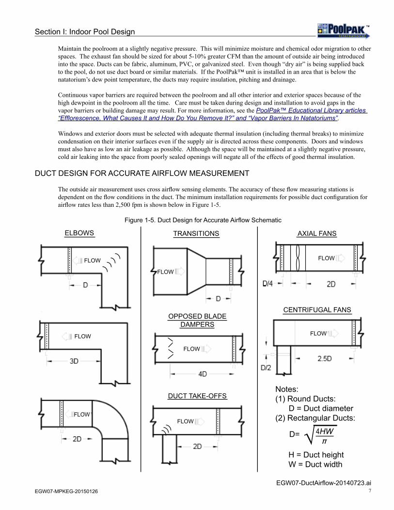
The outside air measurement uses cross airflow sensing elements. The accuracy of these flow measuring stations is dependent on the flow conditions in the duct. The minimum installation requirements for possible duct configuration for airflow rates less than 2,500 fpm is shown below in Figure 1-5.
Figure 1-5. Duct Design for Accurate Airflow Schematic
EGW07-DuctAirflow-20140723.ai
ELBOWS TRANSITIONS AXIAL FANS
CENTRIFUGAL FANS
DUCT TAKE-OFFS
OPPOSED BLADE DAMPERS
√ 4HW�
D=
H = Duct heightW = Duct width
Notes:(1) Round Ducts: D = Duct diameter(2) Rectangular Ducts:
FLOWFLOW
FLOW
FLOW
FLOW
FLOWFLOW
FLOW
FLOW
8 EGW07-MPKEG-20150126
TMTM
SECTION II: POOLPAK PRINCIPLES, FUNCTIONS, AND FEATURES
THE MECHANICAL DEHUMIDIFICATION SYSTEMPRINCIPLES OF OPERATION
The PoolPak™ System is a complete environmental control system designed expressly for indoor swimming pool enclosures. It takes into account two important factors: the swimming pool occupant (personal comfort) and the swimming pool environment (the physical structure and surrounding furnishings).
The swimming pool enclosure can be a hostile environment for equipment, decor and building structures. A PoolPak™ System’s major function is to dehumidify the pool enclosure air through a vapor compression cycle. During this cycle the PoolPak™ system recycles the sensible and latent heat and places it back into the pool water and air as needed. This recycling process saves money and keeps your pool environment efficient and safe.
Solid state microprocessor technology, working in conjunction with sensors, continually monitors water and air conditions to provide superior occupant comfort. Unlike typical outside air ventilation systems, a PoolPak™ System recycles energy and blankets the walls and windows with warm, dry air.
PoolPak™ dehumidification systems reduce the energy input required to maintain pool water and air temperatures. By dehumidifying the air and recycling the latent energy back into the pool air and water, the unit will reduce operating costs when compared to conventional heating and ventilating systems.
A PoolPak™ unit, when matched correctly to the evaporation rate of the pool water and overall dehumidification requirements, will efficiently maintain the pool air at relative humidity levels between 50% and 60%. It should be noted that a lower evaporation rate occurs when the pool enclosure’s air temperature is maintained above the pool water temperature. Evaporation losses, and the energy required to maintain desired room conditions, will dramatically increase if the air temperature is allowed to fall below the pool water temperature. It is recommended that the continuous dry bulb temperature entering the evaporator of the PoolPak™ unit not fall below 75°F.
PoolPak International recommends that backup heating equipment for both pool water and pool enclosure air is capable of carrying the full system heating requirements. This makes for a well-designed system that will provide the least amount of pool down time if unforeseen system problems occur. Building conductive loads and other losses must be taken into consideration when sizing the dehumidification system or the auxiliary heating/cooling equipment.
AUTOMATIC CONTROL OF AIR TEMPERATURE AND HUMIDITY
An integral part of any PoolPak™ system is a proven microprocessor control system which automatically senses and maintains comfort conditions. Sensors detect changes in humidity and air temperature in the indoor pool environment and quickly regulate supply air conditions to meet set point comfort levels, even during periods of unusually heavy pool use.
To prevent condensation on walls and windows, the PoolPak™ system automatically adjusts humidity in response to changes in wall or window surface temperatures. As the seasons and weather conditions change, the PoolPak™ system changes its own mode of operation. Throughout the year, the PoolPak™ thinks “efficiency” and automatically selects the least expensive energy source for the poolroom conditions.
PoolPak™ units include a factory mounted and wired space temperature and humidity sensor at the return air opening of the unit.

9EGW07-MPKEG-20150126
TMTM
!CAUTIONWhen the outside air is to be introduced into the space for ventilation, adequate exhaust capacity via an integral (or a separate external fan) must be specified to ensure the poolroom remains slightly negative. An inadequately sized exhaust system may result in damage to the structure and pool odors may be forced into other areas of the building.
PoolPak™ units have Smart Air Management™ with Variable Frequency Drives (VFD) and air flow monitoring stations on the outside air and fans to provide optimal airflow at lower cost.
ROOM DEW POINT CONTROL
The PoolPak™ unit’s ICC controller operates using an advanced type of control utilizing dew point and dry bulb temperature. This method of control is more accurate than conventional relative humidity control. The main purpose of a dehumidification system is to maintain the amount of moisture in the pool area below a level that would cause damage to the building. Relative humidity is a measurement of the percentage of moisture in the air at a given dry bulb temperature in proportion to the maximum amount of moisture that could be contained at this particular dry bulb temperature. Warmer air can hold more moisture than colder air and, therefore, changes in dry bulb temperature will change the relative humidity reading without any change in the actual amount of moisture in the air. The amount of moisture in the air is expressed as “grains of moisture per pound of dry air” and is directly related to the dew point temperature.
See Figure 2-1 for reference. The ICC uses dew point control to operate the PoolPak™ unit and maintain the moisture level below the setpoint. The space dry bulb temperature and relative humidity determine the dew point temperature. By varying the space temperature and space relative humidity set points, the dew point set point is changed. When the space dew point temperature rises more than 1/2 degree Fahrenheit above the space dew point temperature set point, the ICC controller energizes the compressor for dehumidification. As the dew point temperature drops more than 1/2 degree Fahrenheit below the dew point temperature set point the controller de-energizes the compressor.
Figure 2-1. Dewpoint Control Psychrometric
ALL_DewpointControlPsychro_20131220.eps
0.000
30˚F/-1˚C Dry Bulb Temp.
40˚F/4˚C 50˚F/10˚C 60˚F/16˚C 70˚F/21˚C 80˚F/27˚C 90˚F/32˚C 100˚F/38˚C 110˚F/43˚C 120˚F/49˚C
0.030
0.028
0.024
0.020
0.016
0.012
0.008
0.004
Humidity Ratiolbw / lbaDew Point
82˚F / 28˚C
80˚F / 27˚C
75˚F / 24˚C
70˚F / 21˚C
65˚F / 18˚C
60˚F / 16˚C
55˚F / 13C̊
50˚F / 10˚C
45˚F / 7C̊
40˚F / 4C̊35˚F / 2C̊30˚F / -1˚C
80%
60%
40%
20%
If RA here, space toocold, too humid
If RA here, space toohot, too humid
If RA here, space toocold, humidity OK
If RA here, space toohot, humidity OK
Section II: PoolPak Principles, Functions, and Features
10 EGW07-MPKEG-20150126
TMTM
POOLPAK OPERATION
See Figure 2-2 to illustrate the following paragraphs.
Refrigerant-Side Operation
The PoolPak™ draws in warm, moist air from the pool enclosure. This air passes through the evaporator(dehumidification) coil and gives up heat energy to the refrigerant which is in a cool, liquid state. This exchange of energy causes the air temperature to fall below its dew point, resulting in moisture condensation on the evaporator coil. The moisture formed is collected by the unit’s condensate drain system. After passing through the evaporator coil, the refrigerant becomes a cool gas.
The refrigerant enters the unit’s compressor, where it is compressed into a hot gas. While in the compressor, the refrigerant absorbs the energy used to operate the compressor. This hot gas refrigerant then travels either through an air reheat coil, the pool water condenser or to an optional auxiliary air condensing heat exchanger, which may be either air or water cooled. If air heating is required, the air reheat coil is used. The hot refrigerant exchanges energy with the cooler, dehumidified air coming from the evaporator coil. This causes the temperature of the air to rise for heating.
If pool water heating is required the hot gas flows into a pool water condenser, where it adds energy to the incoming pool water. This heats the pool water while the refrigerant is condensed into a warm liquid. If space cooling is required, the refrigerant flows to the auxiliary air conditioning condenser bypassing the air reheat coil and pool water condenser and allowing cool air from the evaporator coil to provide space cooling.
Air-Side Operation
The poolpak system provides outside air ventilation to satisfy minimum air ventilation requirements during occupied periods per ASHRAE standard 62.1.
The MPK unit can include an outside air damper (MS), a factory mounted exhaust fan (MSE), or an exhaust and purge fan (MSEP).
MSEP models have an economizer function that can modulate up to 100% exhaust air and outside air. This operation allows the unit to use outdoor ambient conditions if they are favorable for free heating, cooling, or dehumidification. For a more detailed description of economizer and smart economizer operation, see the ICC control functions section.
The PoolPak™ unit has been designed to best recycle the energy from the return air during mechanical dehumidification. In cooling modes for units employed with an exhaust fan (MSE & MSEP models), warm natatorium air is exhausted before the evaporator coil. On the other hand, in heating modes for units employed with purge fans (MSEP models), warm natatorium air is exhausted after the evaporator coil. This allows the unit to capture the exhaust air heat energy for heating before exhausting the air to ambient.
An available supply of outdoor air and continuous air movement is required for indoor air quality. Therefore, PoolPak™ does not recommend turning off the unit.
Section II: PoolPak Principles, Functions, and Features

11EGW07-MPKEG-20150126
TMTM
Figure 2-2. MPK System Schematic
MPK-SystemSchematic-20140805.eps
WA
RMRE
TURN
AIR
FRO
MPO
OL
SUPP
LYA
IR
SUPP
LY F
AN
S
T
T
TT
T
HH
H
T
H
COM
PRES
SOR
OU
TSID
E A
IRD
AMPE
R
PURG
EFA
N(S
) PURG
E/EX
HAU
ST A
IR
RECI
RCU
LATI
ON
DAM
PER
MD
EVA
PORA
TOR
COIL
(HEA
TRE
COVE
RYCO
IL)
HO
T LI
QU
ID R
EFRI
GER
AN
TH
OT
GA
S RE
FRIG
ERA
NT
COLD
LIQ
UID
REF
RIG
ERA
NT
COLD
GA
S RE
FRIG
ERA
NT
TEM
PERA
TURE
SEN
SOR
RELA
TIVE
HU
MID
ITY
SEN
SOR
MO
TORI
ZED
DA
MPE
R
OU
TSID
EA
IR
SOLE
NO
ID V
ALV
E
S
S
S
S
TO A
IR-C
OO
LED
CON
DEN
SER
OR
WAT
ER-C
OO
LED
CON
DEN
SER
(OPT
ION
AL)
COO
L PO
OL
WAT
ER
FRO
M A
IR-C
OO
LED
CON
DEN
SER
OR
WAT
ER-
COO
LED
CO
ND
ENSE
R(O
PTIO
NA
L)
WA
RM P
OO
L W
ATER
CON
DEN
SER
REH
EAT
COIL
POO
L W
ATER
CON
DEN
SER
AUXI
LIA
RY P
OO
L W
ATER
HEA
TER
(BY
OTH
ERS)
OPT
ION
AL
AUX
HEA
TIN
G C
OIL
S(H
OT
WAT
ER, S
TEA
M, G
AS
FURN
ACE,
OR
ELEC
TRIC
)O
RAU
X CO
OL
COIL
S (C
HIL
LED
WAT
ER C
OIL
)
EXPA
NSI
ON
VALV
E
LEG
END
RECE
IVER
COLD
SU
RFAC
ETE
MPE
RATU
RESE
NSO
R EX
TERN
AL
TO M
PK
EXH
AUST
FAN
EXH
AUST
AIR
MD
MD
FT
FT
FT
FT
OU
TSID
E A
IR A
IRFL
OW
MEA
SURE
MEN
T SY
STEM
4-20
mA
AIR
FLO
W T
RAN
SDU
CER
(CFM
)VA
RIA
BLE
FREQ
UEN
CY D
RIVE
(FA
N S
PEED
CO
NTR
OL)
FTVFD
VFD
VFD
VFD
Section II: PoolPak Principles, Functions, and Features

12 EGW07-MPKEG-20150126
TMTM
Section II: PoolPak Principles, Functions, and Features
ICC CONTROL FUNCTIONSOVERVIEW
The PoolPak™ is controlled by the Instant Command Center (ICC), a microprocessor-based system that incorporates all of the functions necessary to maintain correct natatorium temperature and humidity and control pool water temperature. The ICC is designed to work with the PoolPak™ dehumidification system to provide an environment that is both comfortable and cost effective. It controls unwanted humidity in the pool enclosure and helps to prevent unsightly condensation from forming on surfaces.
The PoolPak™ controls automatically operate the heating, dehumidification, and heat recovery systems in response to the greatest requirements while adjusting unit outputs to maintain building conditions. The PoolPak™ controls are capable of providing full heating capacity to either air or water and of providing proportional control of heating and dehumidification by loading stages of compressor capacity as necessary. As building requirements are satisfied, the compressor unloads.
All PoolPak™ operating and logic controls are factory mounted and wired. The control sequences are designed specifically to control swimming pool environmental conditions. The following is a brief description of the control functions available with the ICC Control System. For more detail or for finding this information in the controller, see the MPK Installation and Operation Manual (IOM).
AIR FLOW MONITORING AND CONTROL
The best way to control building pressure is by measuring and controlling airflow rates. The PoolPak™ system employs a factory mounted VFD on the supply fan array, exhaust fan, and purge fans to modulate airflow. The controller receives feedback from fan inlet measuring stations and the outdoor air measuring station to continuously monitor the outside air, exhaust air, purge air, and supply air flows. These components and ICC controller logic provide Smart Air ManagementTM.
By tracking the airflow rate of the exhaust fan and outdoor air intake, a consistent building pressure can be maintained. See Figure 2-3 for reference. The ICC takes the outside air flow measurement and controls the speed of the exhaust fan. This control maintains a constant return air flow/supply air flow differential whether the system is operating at the minimum outdoor airflow rate or maximum outdoor airflow rate (ie. economizer mode).
To determine the desired air flow rates, the controller must be programmed with setpoints for the desired supply air flow, the desired return air flow, the minimum outdoor air flow, and minimum mixed air temperature allowed. During minimum outdoor air ventilation, the controller controls the outside air and recirculation air dampers to maintain the minimum ventilation air requirement. During economizer mode, the controller modulates the outside air flow and exhaust air flow to maintain space conditions.

13EGW07-MPKEG-20150126
TMTM
Section II: PoolPak Principles, Functions, and Features
Figure 2-3. Active Airflow Control with Direct OA Measurement Schematic
MPK_EG_VFDAirflowSchematic_20131220.eps
HUMIDITY CONTROL
The primary function of the ICC control system is humidity control. The ICC control system accomplishes humidity control by using either the economizer mode or mechanical dehumidification.
When equipped, the economizer mode is activated only if the following conditions are present: dehumidification is required; air and water temperatures are satisfied; the absolute humidity of the outside air is lower than the absolute humidity of the pool room air; and the outside air temperature will not adversely affect the pool room air temperature. Whenever available, the economizer mode brings in favorable outside air to satisfy the pool room requirements.
When economizer is not available, the PoolPak™ unit performs mechanical dehumidification. The PoolPak™ provides full proportional control of relative humidity by staging unit capacity. The humidity controller energizes the compressor. The moist air from the pool room is drawn over the evaporator coil, where the air is cooled below its dew point. In this cooling process, the moisture in the return air is condensed onto the evaporator coil. The heat recovered in the refrigerant from the dehumidification process is directed to the air reheat condenser if the space needs heating or to the pool water condenser if pool water temperature is below the set point.
4-20mA AIRFLOW TRANSDUCER
MOTORIZED DAMPER WITH FEEDBACK SIGNALVARIABLE FREQUENCY DRIVE (FAN SPEED CONTROL)
LEGEND
MD
FT
VFD
ICC
WARMRETURNAIR FROMPOOL
SUPPLYAIR
SUPPLY FANS
OUTSIDE AIRDAMPER
PURGEFANS
PURGE/EXHAUST AIR
RECIRCULATIONDAMPER
MD
OUTSIDEAIR
EXHAUSTFAN
EXHAUST AIR
MDFTFT
FT
FT
OUTSIDE AIR FLOWMEASUREMENT SYSTEM
VFD
VFD
VFD

14 EGW07-MPKEG-20150126
TMTM
COLD SURFACE TEMPERATURE HUMIDITY RESET
The ICC control system includes a sensor that measures the temperature of the coldest surface in the pool enclosure, usually an exterior window or door frame. When the temperature of this surface approaches the dewpoint temperature of the space, the controller lowers the humidity setpoint to activate dehumidification. This function helps to prevent condensation on the cold surface. Typical locations for this condensate prevention surface temperature sensor are north facing exterior walls, windows, window/door frames, and skylights.
SPACE HEATING
The ICC controller will first look at the outside air to see if the space heating requirement can be met with the economizer mode. If conditions are unfavorable, the unit will either enable the compressors to perform space heating by heat recovery or by enabling the auxiliary heat system. Space heating via heat recovery provides full proportional control of the space dry bulb temperature by staging compressor loading of unit capacity with humidity override. Heat is recovered automatically from the pool room return air in the evaporator coil and then re-directed into the reheat condenser coil. For MSEP models, the warm natatorium air is passed through the evaporator before being exhausted. Therefore, the PoolPak™ unit is able to capture the heat energy from the warm pool air.
If additional heating is needed, the ICC Controller then turns on the auxiliary heat system. The PoolPak™ automatically controls the output of the optional factory-installed auxiliary air-heating system which can be hot water, steam, electric or gas.
On a call for space heating only (humidity is satisfied), the controller can be configured to perform the first stage(s) of heat as auxiliary heat instead. If there is also a dehumidification need, mechanical dehumidification with the compressors will always be the first stage. Regardless, this setting change allows a facility to use auxiliary heat more often.
SMART ECONOMIZER (MSEP)
The Smart Economizer utilizes the simultaneous operation of the heat recovery and economizer control sequence. When the PoolPak™ compressor is operating in the heating and/or dehumidifying heat recovery mode return air passes through the evaporator. The sensible and latent heat in the return air is transferred to the refrigerant. Air leaving the evaporator is cold and saturated. The exact temperature and dew point of the air leaving the evaporator is monitored and compared to outside air temperature and dew point. If the outside air is warmer and/or dryer than the air leaving the evaporator, all the air leaving the evaporator is exhausted and 100% outside air is drawn into the PoolPak™. All the heat recovered in the PoolPak™ unit refrigerant is transferred to the supply air in the air reheat condenser. The Smart Economizer can save energy in addition to a standard mixing box and economizer.
FLYWHEEL AIR CONDITIONING (MSEP)
If the unit is not equipped with auxiliary air cooling, this control sequence can be activated. Flywheel air conditioning uses the large thermal storage capacity of the swimming pool. During occupied times, the PoolPak™ cools the natatorium air by removing the sensible and latent heat from the air using the evaporator and directing it into the pool water condenser. The pool water temperature is allowed to rise a maximum of 2°F above the pool water temperature set point. Automatic staging of cooling capacity occurs in response to air conditioning load.
SPACE COOLING (OPTIONAL)
The PoolPak™ MPK (MSE and MSEP) units are equipped with economizer sections. The ICC will automatically select the most economical method for space cooling. An economizer utilizes outside air rather than the refrigeration system to achieve space cooling. A sensor connected to the ICC monitors the outside air temperature. When appropriate, the controller will disable the compressor and bring in cool outside air for economical operation.
Section II: PoolPak Principles, Functions, and Features

15EGW07-MPKEG-20150126
TMTM
Section II: PoolPak Principles, Functions, and Features
If space cooling is required and the unit is equipped with an auxiliary refrigerant condenser (air-cooled or water-cooled), the ICC will activate the space cooling mode of operation. The air cooling mode of operation is independent of the need for dehumidification. In this compressor mode, the heat removed from the space air by the evaporator will be directed to the auxiliary condenser. For MSE and MSEP units, the air is exhausted before the evaporator. By exhausting the warm air before the evaporator, the highest enthalpy air is removed from the system which reduces the load on the air cooled condenser.
Air Conditioning with Air-Cooled Condenser
The PoolPak™ can be equipped with a properly sized integral or remote air-cooled condenser. The remote condenser can also be installed on a separate pad.
Air Conditioning with Water-Cooled Condenser
The PoolPak™ can be equipped with a remote-mounted water-cooled condenser. This condenser can be either cleanable or non-cleanable. Sensible and latent heat recovered in the air conditioning mode is rejected to the water condenser if pool water temperature requirements are satisfied.
Air Conditioning with Chilled Water Coil
When chilled water is available, a chilled water coil can be factory-installed upstream of the supply fan. The coil has a factory-installed and wired three-way flow control valve and is controlled by the PoolPak™ control system.
POOL WATER HEATING
If the space temperature is at or above the set point and the pool water temperature is below the set point, hot gas is directed to the pool water condenser when the compressor is running. During times when the pool water requires more heat than is available from the pool water condenser, the PoolPak™ activates the auxiliary pool water heater. An auxiliary pool water heater must be supplied as part of the pool water pump and filter system.
NOTEContact factory for pool water temperature set points greater than 87°F.
SMART PUMP CONTROL™ (OPTIONAL)
Smart Pump Control™ allows the ICC to control operation of a field-installed booster pump to the PoolPak™ pool water condenser. When the ICC determines that pool heating and space cooling are required, a contact closure signal activates the remote pump. The pump will be deactivated when the pool heating and space cooling requirement is satisfied. This control sequence requires separate field mounting of a factory supplied pool water temperature sensor where continuous pool water flow is expected.
NETWORKING MULTIPLE UNITS
ICC networking allows multiple units to be connected together. The units will work with each other to control water temperature, air temperature and relative humidity. Networked units have all the features of standard units plus the ability to control water temperature in multiple pools. All units on the network are accessible from a single remote interface unit for convenience.
OCCUPIED/UNOCCUPIED CONTROL MODE
The PoolPak™ unit time clock allows 7-day, 24-hour scheduling of operational control for both occupied and unoccupied times during the year. During unoccupied times, the outside air damper and exhaust fans are kept in the closed/off position. This strategy minimizes the air-heating and/or air-cooling load during unoccupied periods. Also during unoccupied mode, the supply fan speed is reduced by 20% (Night Fan Setback) further reducing fan energy costs. During occupied times, the PoolPak™ operates to maintain outside air at programmed natatorium parameters.
16 EGW07-MPKEG-20150126
TMTM
PURGE MODE (MSEP)
The PoolPak™ has a purge cycle to fully ventilate the natatorium at the airflow (CFM) specified for the unit’s supply fan. The purge cycle is programmable by the owner as necessary to ventilate the natatorium after shocking the pool. Unit controls provide completely automatic operation by controlling the supply fan and return (or purge) fan and by opening the outside air and exhaust air dampers for the programmed time intervals.
EVENT MODE (MSEP)
The Event Mode changes the ventilation air quantity to meet the demands of an event or situation where additional outside air is needed. The unit controller can store up to 28 schedule events, which are user adjustable at the Remote User Interface (RUI). During Event Mode, the minimum damper position is raised to a value higher than the minimum damper setpoint. For each event, the screen shows the day of the week, the hour in 24-hour format, the minute, and the event type.
SUMMER VENTILATION MODE (MSEP)
Summer Ventilation Mode permits the pool operator to open the doors and windows during the summer. The ICC control system uses the space doors and windows as its outside air intake by closing the unit’s outside air damper while driving to full 100% exhaust mode through the exhaust and purge dampers at the PoolPak™ unit.
CO2 BASED DEMAND VENTILATION (OPTIONAL)
The amount of outside air ventilation is controlled by the PoolPak™ unit based on the CO2 level sensors in the return air stream.
Section II: PoolPak Principles, Functions, and Features

17EGW07-MPKEG-20150126
TMTM
Section II: PoolPak Principles, Functions, and Features
FEATURES AND OPTIONSSTANDARD FACTORY MOUNTED FEATURES
• Direct drive plenum fans• Variable frequency drives• Two inch, double wall, foam insulated panels• Airflow monitoring (transducers located on fans and outside air)• Evaporator coil (heat recovery coil) • Air reheat condenser coil• Pool water condenser coil• Compressor performance monitoring: suction and discharge pressure transducers• Supply air configuration: all sides available. • Dampers: outside air, recirculation air, evaporator bypass air• Gravity relief dampers on exhaust and purge (MSE/MSEP)• Temperature (T) and relative humidity (H) sensors:• Return air, T and H• Air of the evaporator, T and H• Supply air, T• Pool water, T• Compressor suction temperature, T• Filters and filter rack (return and outside air)• Dirty filter indicator• Network multiple units – connect up to 5 units• Weatherproofing for outdoor installation
STANDARD FACTORY SUPPLIED, FIELD INSTALLED FEATURES
• Temperature (T) and relative humidity (H) Sensors:• Cold surface temperature sensor, T• Outside air, T and H• Pool water, T (only if Smart Pump Control™ option is selected) • Remote Interface Unit (RIU)
OPTIONAL FACTORY MOUNTED FEATURES
• Integral hot water coil and valve• Integral auxiliary heat module (gas furnace or electric heat)• Integral air cooled condenser and associated refrigerant piping• Integral chilled water coil and valve• Remote exhaust fan control• Remote monitoring via internet• Building automation system connection (LonWorks, Modbus, or BACnet)• Freeze protection• Smart Pump Control™
OPTIONAL FIELD INSTALLED FEATURES
• Remote air-cooled condenser and associated refrigerant piping• Remote auxiliary water-cooled condenser or cooling tower and associated water or refrigerant piping• Building automation system external components and wiring• Remote space pressure monitoring• Remote exhaust fan
18 EGW07-MPKEG-20150126
TMTM
SELECTION
PoolPak™ unit selection software is more than an equipment sizing program. It is designed to accurately calculate the entire moisture load for your application. The program incorporates the key design parameters, including ASHRAE ventilation requirement, to help guide the user in meeting the necessary codes. The program also calculates the ventilation load with the outside air airflow requirement that is specified.
The basic data that would generally need to be entered to calculate a load includes:
• Indoor dry bulb temperature (°F) • Indoor relative humidity (%) • Room volume (cu ft) • Total wet surface area of the pool room (sq ft)• Total dry surface area of the pool room (sq ft) • Spectator count • Pool temperature (°F) • Pool usage (activity factor: light, medium, and heavy) • Pool type (swimming pool, wave pool, therapy, and others) • Outside airflow design (CFM)
Above and other information required for the program can be found in the PoolPak Engineering Library article “PoolPak™ Selection Input Data”. Please contact your exclusive PoolPak Sales representative for a selection.
Section II: PoolPak Principles, Functions, and Features

19EGW07-MPKEG-20150126
TMTM
SECTION III: SIZING AND PERFORMANCEPOOLPAK UNIT DIMENSIONS AND WEIGHTS
Figure 3-1. MPK Dimensional Isometric View
MPK_EG_DimISO_20140114.eps
Table 3-1. MPK Dimensions and Weights
RETURN AIR (BOTTOM)
INTEGRAL AUXILIARY
HEAT MODULE SUPPLY AIR
EXHAUST AIR
BASE MPK UNIT
OU
TSID
E A
IR
LENGTH (L)
LENGTH (L)LENGTH (L)
LENGTH (L)
(H)
HEIGHT
WIDTH (W)
LENGTH (L)INTEGRAL AUXILIARY
HEAT MODULE
BASE MPK UNIT
RIGHTVIEW
FRONTVIEW
REARVIEW
INTEGRAL AIR COOLED
CONDENSER
LEFTVIEW
INTEGRAL AIR COOLED
CONDENSER
AIR FLOW
Unit Configuration
Cabinet Size (Inches, x 1000 lbs)
B (101” W x 96” H) C (101” W x 108” H) D (101” W x 120” H)
Length Weight Range* Length Weight Range* Length Weight Range*
MS / MSE 292 9.6 to 12.9 337 12.8 to 17.0 337 13.6 to 18.2
MS / MSE w/ Integral ACC 410 12.0 to 16.0 435 15.8 to 21.0 435 16.7 to 22.2
MS / MSE w/ Furnace 378 11.7 to 15.6 447 16.3 to 21.7 447 17.1 to 22.9
MS / MSE w/ Elec Heater 359 11.2 to 15.0 404 14.5 to 19.3 404 15.3 to 20.4
MS / MSE w/ACC + Furnace 496 14.0 to 18.7 545 19.3 to 25.7 545 20.2 to 26.9
MS / MSE w/ACC + Elec Heater 477 13.6 to 18.1 502 17.5 to 23.3 502 18.4 to 24.5
MSEP 341 10.9 to 14.6 394 14.7 to 19.6 394 15.6 to 20.8
MSEP w/ Integral ACC 458 13.3 to 17.7 492 17.7 to 23.6 492 18.6 to 24.8
MSEP w/ Furnace 427 13.0 to 17.4 504 18.2 to 24.3 504 19.2 to 25.4
MSEP w/ Elec Heater 408 12.5 to 16.7 461 16.4 to 21.9 461 17.3 to 23.0
MSEP w/ACC + Furnace 544 15.4 to 20.5 602 21.2 to 28.3 602 22.1 to 29.5
MSEP w/ACC + Elec Heater 525 14.9 to 19.8 559 19.4 to 25.9 559 20.3 to 27.0
* Weight varies depending on options selected. Contact factory for a selected unit weight.

20 EGW07-MPKEG-20150126
TMTM
MPK PERFORMANCE SUMMARY
Table 3-2. MPK Unit Performance (at 82°F and 60% RH)
MPK FACTORY CHARGE
Table 3-3. MPK Factory Refrigerant Charge(lbs of R-410A)
MPK Model#
Evap Coil Type1
Moisture Removal Rate
(Lb/Hr)
Evaporator Total Capacity (MBH)
Evaporator Sensible Capacity
(MBH)
Compressor Input Power
(KW)
Total Heat Rejection
(MBH)
Reheat Capacity
(MBH)
B - cabinet (10-22 kCFM)B030 Std (HiS) 177 (176) 401 (425) 217 (242) 29.2 (28.2) 496 (516) 496 (516)B035 Std (HiS) 198 (205) 449 (485) 243 (272) 33.4 (32.5) 557 (590) 557 (590)B040 Std (HiS) 221 (232) 499 (550) 269 (309) 37.5 (36.6) 621 (669) 621 (669)B045 Std (HiS) 240 (259) 545 (607) 295 (338) 42.1 (41.3) 681 (741) 681 (741)B050 Std (HiS) 278 (302) 627 (696) 338 (382) 48.0 (47.6) 783 (850) 783 (850)
C - cabinet (17-30 kCFM)C035 Std (HiS) 198 (205) 449 (485) 243 (272) 33.4 (32.5) 557 (590) 557 (590)C040 Std (HiS) 221 (232) 499 (550) 269 (309) 37.5 (36.6) 621 (669) 621 (669)C045 Std (HiS) 240 (259) 545 (607) 295 (338) 42.1 (41.3) 681 (741) 681 (741)C050 Std (HiS) 278 (302) 627 (696) 338 (382) 48.0 (47.6) 783 (850) 783 (850)C060 Std (HiS) 329 (350) 743 (813) 401 (449) 56.9 (55.5) 927 (993) 927 (993)C070 Std (HiS) 377 (412) 852 (946) 460 (518) 63.0 (63.5) 1056 (1152) 1056 (1152)
D - cabinet (23-40 kCFM)D060 Std (HiS) 329 (350) 743 (813) 401 (449) 56.9 (55.5) 927 (993) 927 (993)D070 Std (HiS) 377 (412) 852 (946) 460 (518) 63.0 (63.5) 1056 (1152) 1056 (1152)D080 Std (HiS) 437 (455) 977 (1056) 523 (583) 74.6 (74.8) 1219 (1299) 1219 (1299)D090 Std 472 1061 570 80.1 1321 1321
1
HiS = High Sensible Cooling Capacity option data in parentheses
MPK Model # Without Integral ACC With Integral ACCCircuit 1 Circuit 2 Circuit 3 Circuit 1 Circuit 2 Circuit 3
B - cabinetB030 70 70 - 85 85 -B035 70 90 - 85 110 -B040 70 95 - 85 120 -B045 90 95 - 110 120 -B050 90 115 - 110 145 -
C - cabinetC035 70 90 - 85 110 -C040 70 95 - 85 120 -C045 90 95 - 110 120 -C050 90 115 - 110 145 -C060 90 90 90 110 110 110C070 90 95 95 110 120 120
D - cabinetD060 90 90 90 110 110 110D070 90 95 95 110 120 120D080 95 95 115 120 120 145D090 95 115 115 120 145 145
Section III: Sizing and Performance

21EGW07-MPKEG-20150126
TMTM
Section III: Sizing and Performance
POOLPAK PROVIDED REMOTE ACC SPECIFICATIONS
Table 3-4. PoolPak™ Provided Remote ACC SpecificationsNote: Below table contains the piping sizes of the remote ACC stub-outs. Additional field piping may be needed to make the transition from the ACC connections to correct refrigeration lineset sizing (See Table 4-1).
Remote ACC product drawings are available on the PoolPak website in the MPK Product Drawings folder.
NON-POOLPAK-PROVIDED AIR-COOLED CONDENSER SELECTION PROCEDURE
The procedure for selecting an optional remote air-cooled condenser is:
1. Find the unit’s total heat rejection capacity from the MPK Unit Performance table.
EXAMPLE (for MPK D060): Heat Rejection Capacity = 927,271 Btu/hr
2. Determine the difference between 120°F (the PoolPak design condensing temperature) and the design outdoor dry bulb temperature.
3. For the given Heat Rejection Capacity and temperature difference (from step 2), select the proper sized condenser using R-410A refrigerant.
Refrig Sys Size
Ambient Air Temp
ACC Model
Fan Qty Refrigerant Connection Sizes
Weight ACC Voltage FLA MCA MOPwide longCircuit 1 Circuit 2 Circuit 3
Gas Liq Gas Liq Gas Liq
030 95/100/ 105 MAC0532 2 2 1-3/8 7/8 1-3/8 7/8 - - 3,170
208/230-3-60 36 38.3 45460-3-60 18 19.1 25575-3-60 15.2 16.1 20
035 95/100/ 105 MAC0602 2 2 1-3/8 7/8 1-3/8 1-1/8 - - 3,220
208/230-3-60 36 38.3 45460-3-60 18 19.1 25575-3-60 15.2 16.1 20
040 95/100/ 105 MAC0682 2 2 1-3/8 7/8 1-5/8 1-1/8 - - 3,300
208/230-3-60 36 38.3 45460-3-60 18 19.1 25575-3-60 15.2 16.1 20
045 95/100/ 105 MAC0742 2 2 1-3/8 1-1/8 1-5/8 1-1/8 - - 3,330
208/230-3-60 36 38.3 45460-3-60 18 19.1 25575-3-60 15.2 16.1 20
050 95/100/ 105 MAC0842 2 2 1-3/8 1-1/8 1-5/8 1-3/8 - - 3,370
208/230-3-60 36 38.3 45460-3-60 18 19.1 25575-3-60 15.2 16.1 20
060 95/100/ 105 MAC1003 2 3 1-3/8 1-1/8 1-3/8 1-1/8 1-3/8 1-1/8 3,730
208/230-3-60 54 56.3 60460-3-60 27 28.1 30575-3-60 22.8 23.8 25
070 95/100/ 105 MAC1163 2 3 1-3/8 1-1/8 1-5/8 1-1/8 1-5/8 1-1/8 3,920
208/230-3-60 54 56.3 60460-3-60 27 28.1 30575-3-60 22.8 23.8 25
080 95/100/ 105 MAC1353 2 3 1-5/8 1-1/8 1-5/8 1-1/8 1-5/8 1-3/8 4,050
208/230-3-60 54 56.3 60460-3-60 27 28.1 30575-3-60 22.8 23.8 25
090 95/100/ 105 MAC1483 2 3 1-5/8 1-1/8 1-5/8 1-3/8 1-5/8 1-3/8 4,100
208/230-3-60 54 56.3 60460-3-60 27 28.1 30575-3-60 22.8 23.8 25
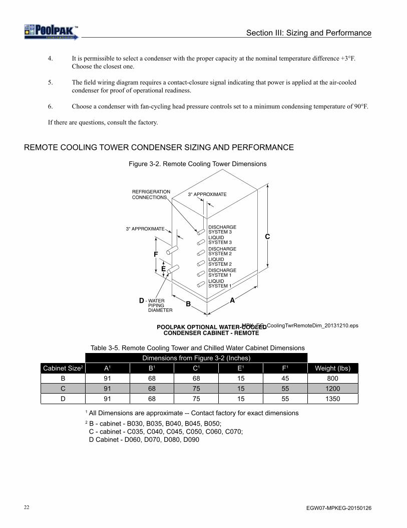
22 EGW07-MPKEG-20150126
TMTM
Section III: Sizing and Performance
4. It is permissible to select a condenser with the proper capacity at the nominal temperature difference +3°F. Choose the closest one.
5. The field wiring diagram requires a contact-closure signal indicating that power is applied at the air-cooled condenser for proof of operational readiness.
6. Choose a condenser with fan-cycling head pressure controls set to a minimum condensing temperature of 90°F.
If there are questions, consult the factory.
REMOTE COOLING TOWER CONDENSER SIZING AND PERFORMANCE
Figure 3-2. Remote Cooling Tower Dimensions
Table 3-5. Remote Cooling Tower and Chilled Water Cabinet Dimensions(dimensions in inches)
F
E
B A
C
REFRIGERATIONCONNECTIONS
3" APPROXIMATE
3" APPROXIMATE
POOLPAK OPTIONAL WATER-COOLEDCONDENSER CABINET - REMOTE
D - WATER PIPING DIAMETER
DISCHARGESYSTEM 2LIQUIDSYSTEM 2
DISCHARGESYSTEM 3LIQUIDSYSTEM 3
LIQUIDSYSTEM 1
DISCHARGESYSTEM 1
Dimensions from Figure 3-2 (Inches)Cabinet Size2 A1 B1 C1 E1 F1 Weight (lbs)
B 91 68 68 15 45 800C 91 68 75 15 55 1200D 91 68 75 15 55 1350
1 All Dimensions are approximate -- Contact factory for exact dimensions2 B - cabinet - B030, B035, B040, B045, B050; C - cabinet - C035, C040, C045, C050, C060, C070; D Cabinet - D060, D070, D080, D090
MPK_EG_CoolingTwrRemoteDim_20131210.eps

23EGW07-MPKEG-20150126
TMTM
Section III: Sizing and Performance
Table 3-6. Remote Cooling Tower and Chilled Water Line Sizes
WATER COOLED CONDENSER SIZING AND PERFORMANCE
Table 3-7. WCC Performance
ModelWater Piping
CPVC Dia (in.)
Refrigeration Connections (Inches)System 1 System 2 System 3
Discharge Liquid Discharge Liquid Discharge Liquid030 2 1-3/8 7/8 1-3/8 7/8035 2 1-3/8 7/8 1-3/8 1-1/8040 2 1-3/8 7/8 1-5/8 1-1/8045 2 1-3/8 1-1/8 1-5/8 1-1/8050 3 1-3/8 1-1/8 1-5/8 1-3/8060 3 1-3/8 1-1/8 1-3/8 1-1/8 1-3/8 1-1/8070 3 1-3/8 1-1/8 1-5/8 1-1/8 1-5/8 1-1/8080 3 1-5/8 1-1/8 1-5/8 1-1/8 1-5/8 1-3/8090 3 1-5/8 1-1/8 1-5/8 1-3/8 1-5/8 1-3/8
ModelCooling Tower Water
Condenser1 Chilled Water Condenser 2 Heat Rejection3
gpm Water (ft)4 gpm Water (ft)5 MBH
030 55 31 40 20 500
035 65 28 50 25 560
040 75 35 60 30 620
045 85 30 65 34 680
050 95 32 70 34 780
060 105 18 80 28 930
070 125 28 100 35 1060
080 150 33 115 36 1220
090 165 35 130 38 1320
1 Maximum 90 °F EWT 2 Maximum 55 °F EWT4 Cleanable, vented condenser 5 Spiral, vented condenser3 Heat rejection at 120 °F Condensing Temperature

24 EGW07-MPKEG-20150126
TMTM
POOLPAK POOL WATER CONDENSER
Table 3-8. Pool Water Capacity
Model Pool Water GPM3 Water (WC-ft)1 Water (WC-ft)2 Heating
Capacity (MBH)
Full Water Condenser
030 55 31 27 500035 65 28 23 560040 75 35 30 620045 85 30 29 680050 95 32 30 780060 105 18 15 930
070 130 28 25 1060
080 150 35 32 1220
090 165 38 35 1320
Partial Water Condenser
030 30 26 24 250
035 30 26 24 250
040 30 26 24 250
045 35 24 22 300
050 35 24 22 300
060 35 24 22 300
070 35 24 22 300
080 45 34 32 370
090 45 34 32 370
1Cleanable, vented condenser (double wall).2Spiral, vented condenser (double wall).3Minimum required pool water flow measured at the unit.
Section III: Sizing and Performance
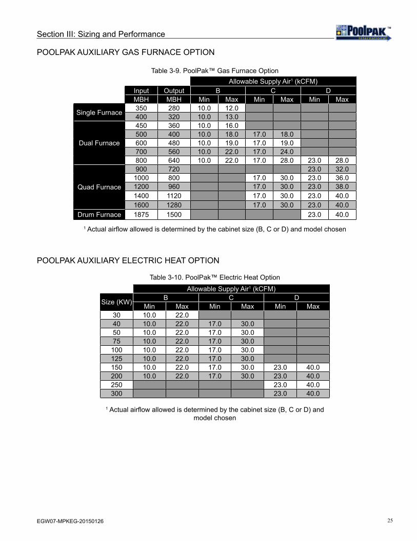
25EGW07-MPKEG-20150126
TMTM
Section III: Sizing and Performance
POOLPAK AUXILIARY GAS FURNACE OPTION
Table 3-9. PoolPak™ Gas Furnace Option
POOLPAK AUXILIARY ELECTRIC HEAT OPTION
Table 3-10. PoolPak™ Electric Heat Option
Allowable Supply Air1 (kCFM)Input Output B C DMBH MBH Min Max Min Max Min Max
Single Furnace 350 280 10.0 12.0400 320 10.0 13.0
Dual Furnace
450 360 10.0 16.0500 400 10.0 18.0 17.0 18.0600 480 10.0 19.0 17.0 19.0700 560 10.0 22.0 17.0 24.0800 640 10.0 22.0 17.0 28.0 23.0 28.0
Quad Furnace
900 720 23.0 32.01000 800 17.0 30.0 23.0 36.01200 960 17.0 30.0 23.0 38.01400 1120 17.0 30.0 23.0 40.01600 1280 17.0 30.0 23.0 40.0
Drum Furnace 1875 1500 23.0 40.0
1 Actual airflow allowed is determined by the cabinet size (B, C or D) and model chosen
Allowable Supply Air1 (kCFM)
Size (KW) B C DMin Max Min Max Min Max
30 10.0 22.040 10.0 22.0 17.0 30.050 10.0 22.0 17.0 30.075 10.0 22.0 17.0 30.0100 10.0 22.0 17.0 30.0125 10.0 22.0 17.0 30.0150 10.0 22.0 17.0 30.0 23.0 40.0200 10.0 22.0 17.0 30.0 23.0 40.0250 23.0 40.0300 23.0 40.0
1 Actual airflow allowed is determined by the cabinet size (B, C or D) and model chosen

26 EGW07-MPKEG-20150126
TMTM
SECTION IV: INSTALLATIONMPK INSTALLATIONINTRODUCTION
Installation requires the unit to be placed on a roof mounted curb, in a mechanical room or outside on an equipment housekeeping pad. Isolation pads should be placed under the unit to minimize transmission of noise due to unit operation. Then pool water is piped to the unit. Electrical power from a properly sized fused disconnect is connected to the unit. The supply and return air ducts are connected to their respective locations on the unit. The condensate is piped back to the pool or to the sewer. If an optional remote air-cooled condenser is used, place the condenser in a proper outdoor location. Refrigerant piping is then run from the air cooled condenser to the PoolPak™ unit. Refrigerant lines must be leak checked and evacuated through installer provided Schrader valves. Control and power wiring are run to complete the installation. If a field-furnished auxiliary space heating coil is installed, the control for this heater must be field wired to the PoolPak™ control panel as shown in the field wiring diagram (Figure 6-3).
Figure 4-1. Typical PoolPak™ Rooftop Installation
MPK_EG_3D_Installation_20131211.eps
OUTSIDE AIRTEMPERATUREAND HUMIDITYSENSORS
OUTSIDE AIR RAINHOOD/BIRD SCREEN
SUPPLYAIR DUCT
AUXILIARY HOT WATER COILSUPPLY AND RETURN LINES
SUPPLY AIR
COLD WALLTEMPERATURESENSOR
CONDENSATERETURN LINE
RETURN AIR
POOL WATERRETURN LINE
MAIN POOLWATER PUMP
REMOTE POOLWATER SENSOR
AUXILIARYPOOL WATERPUMP
POOLFILTER
POOLWATERSUPPLYLINE
CONDENSATERETURN LINE
BALANCINGVALVE
BALANCINGVALVE
AUXILIARY POOLWATER HEATERAQUA STATSENSOR
POOL WATERSUPPLY LINE
AUXILIARYPOOL WATERHEATER
FIRE STAT ANDSMOKE DETECTOR(OPTIONAL)
REMOTEAIR COOLEDCONDENSER(OPTIONAL)
AUXILIARYPOOL WATERHEATERAQUA STAT(TO POOLPAK)
FULL ROOFCURB MOUNTING
REMOTEAIR COOLEDCONDENSER(OPTIONAL)
POOL WATERLINES
RETURNDUCT
CURB
SUPPLYDUCT
AUXILIARYWATERCOIL LINES
enter
alarm
on-off
POOLROOM
DEHUMIDIFIERPOOLPAK ECC lll
CONDENSATELINE
FUSED POWERDISCONNECTS
Modbus RTU
LonWorks
INTERNETCONNECTION
ECC REMOTEDISPLAY/KEYPADPANEL
R
BACnet
R

27EGW07-MPKEG-20150126
TMTM
Section IV: Installation
HANDLING
Care should be taken during handling to avoid damage to panels, drain piping, etc. The PoolPak™ can be moved into position using pipe rollers underneath the base of the unit or it can be lifted using a crane or a hoist attached through the lifting points provided on the unit base frame. If the unit is set temporarily, the unit must be supported under each lifting point.
Use suitable spreaders or a frame to prevent damage to the PoolPak™. Cables must be adjusted to keep the unit level during the lift.
!CAUTIONLifting hooks must be blocked away from the side of the unit to prevent damage to the door panels while lifting. Do NOT walk on top of the unit or serious damage may result.
Failure to follow these directions will result in serious damage to the unit. PoolPak™ will not accept responsibility or liability for repairing any resulting damage.
RIGGING
PoolPak™ units require the use of spreader bars that are at least as wide as the unit. Care must be taken to prevent damage from the chains or slings used in rigging. In general, two to four lifting points are provided on each side of the unit, depending on the unit size and length. All provided lifting points must be used to prevent unit damage. Proper lifting technique for each unit type is provided by a decal on that unit. For outdoors units, take special care to avoid damaging the TPO roofing membrane on the top of the unit during rigging.
CLEARANCE
The clearance for service and repair must be 4 feet on all sides. For less than 4-foot clearances, consult your local PoolPak™ representative or the factory.
DUCT INSTALLATION
Duct Installation is a major part of unit installation. See Ductwork Design in Section I - Indoor Pool Design in the MPK Engineering Guide for more information.
MOUNTING
The PoolPak™ unit is designed for indoor or outdoor locations, either ground-level or roof-top. The location must allow for free condensate drainage (without freezing), ventilation, supply, and return ducts, and sufficient clearance for servicing the unit.
For ground-level installation, precautions should be taken to protect the unit from tampering by or injury to unauthorized personnel. Safety precautions such as a fenced enclosure or additional locking devices on the panels or doors are advisable. Check with local authorities for safety regulations.

28 EGW07-MPKEG-20150126
TMTM
Section IV: Installation
FOUNDATION
The unit must be mounted on a flat and level foundation capable of supporting the entire operating weight of the equipment. The unit MUST NOT set flat on a concrete slab. The PoolPak™ unit MUST BE raised at least 6 inches to allow for sufficient height to adequately trap the condensate lines and to allow for electrical service entrance. The unit must be supported at each lifting point and all corners. Each support should be at least 12 inches long. The unit must be level to ensure proper condensate drainage. If the unit is elevated beyond the normal reach of service personnel, a catwalk capable of supporting service personnel, their equipment, and the scroll compressor(s) (about 1,000 lb.) must be constructed around the unit.
For ground-level installation, a one-piece concrete slab with footers that extend below the frost line is highly recommended. Additionally, the slab should not be tied to the main building foundations to prevent noise transmission. The unit must be supported with adequate space to allow for a condensate line trap.
For roof-top installation, choose a location with adequate structural strength to support the entire weight of the unit and service personnel. For non-curb mounted units, provide spring vibration isolation to minimize vibration transmission to the roof structure. The unit must be situated with adequate height for a condensate line trap. The PoolPak™ unit may be mounted on equipment rails with spring vibration isolation. For any alternative mountings not discussed here, contact the factory for additional guidance. Care must be taken not to damage the roof. If the roof is bonded, consult the building contractor for allowable installation procedures.
INSPECTION
Immediately upon receiving the unit, inspect it for damage which may have occurred during transit. If damage is evident, note it on the carrier’s freight bill. A written request for inspection by the carrier’s agent should be made at once.
UNIT HOOKUP
Avoid tearing or damaging unit insulation while working on or around the unit. Do not stack access panels. Stand them upright with the insulation away from traffic.
Gas Furnace Auxiliary Heat Option
When using a gas furnace, power venting is provided for all unit sizes. External vent piping and/or cap is required. Please refer to the furnace manufacturer’s manual for piping and venting instructions. Install, leak-test, and properly regulate piping for the gas-fired heater. Pressures should be regulated to the entering pressures as shown on the furnace manufacturer’s data plate or manual.
Power Supply
The contractor is required to supply (unless supplied as an option by PoolPak™) and install separate fused disconnect(s) within easy accessibility of the PoolPak™ unit. Use the minimum circuit capacity listed on the unit’s data plate to determine the minimum wire size for incoming electrical power. The ground connection for the unit is located in the unit control panel. The power supply to the unit must be adequate for the compressor starting amperage (LRA). All field wiring must
If a remote air-cooled condenser is required, a separate power feed must be provided for the air-cooled condenser.When the auxiliary electric heater option is provided, another power connection point is provided in the electric heat compartment. This power connection feeds the auxiliary electric heating coil. With this option, the contractor is required to supply and install a second fused disconnect.
PoolPak™ MPK units are available in single and dual point power supply options. See illustrations below.
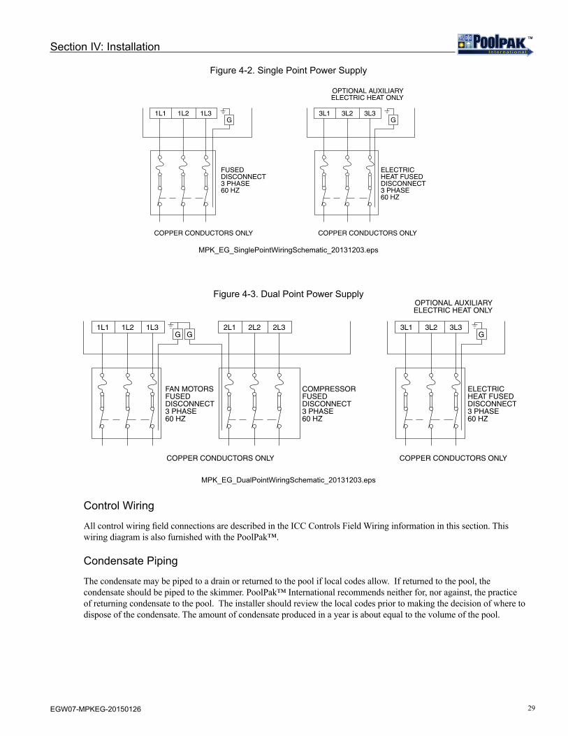
29EGW07-MPKEG-20150126
TMTM
Section IV: Installation
Figure 4-2. Single Point Power Supply
3L1 3L2 3L3G
ELECTRICHEAT FUSEDDISCONNECT3 PHASE60 HZ
COPPER CONDUCTORS ONLY
OPTIONAL AUXILIARYELECTRIC HEAT ONLY
1L1 1L2 1L3G
FUSEDDISCONNECT3 PHASE60 HZ
COPPER CONDUCTORS ONLY
MPK_EG_SinglePointWiringSchematic_20131203.eps
Figure 4-3. Dual Point Power Supply
3L1 3L2 3L3G
ELECTRICHEAT FUSEDDISCONNECT3 PHASE60 HZ
COPPER CONDUCTORS ONLY
OPTIONAL AUXILIARYELECTRIC HEAT ONLY
1L1 1L2 1L3G
FAN MOTORSFUSEDDISCONNECT3 PHASE60 HZ
2L1 2L2 2L3
COMPRESSORFUSEDDISCONNECT3 PHASE60 HZ
COPPER CONDUCTORS ONLY
G
MPK_EG_DualPointWiringSchematic_20131203.eps
Control Wiring
All control wiring field connections are described in the ICC Controls Field Wiring information in this section. This wiring diagram is also furnished with the PoolPak™.
Condensate Piping
The condensate may be piped to a drain or returned to the pool if local codes allow. If returned to the pool, the condensate should be piped to the skimmer. PoolPak™ International recommends neither for, nor against, the practice of returning condensate to the pool. The installer should review the local codes prior to making the decision of where to dispose of the condensate. The amount of condensate produced in a year is about equal to the volume of the pool.
30 EGW07-MPKEG-20150126
TMTM
Section IV: Installation
Curb Mounting
Curbs have been designed specifically for the PoolPak™ product line. Contact factory for roof curb dimensions. The outside dimensions of the curb are such that the base of the PoolPak™ overhangs the edge of the curb on each side. This aids in preventing rain water, running down the sides of the unit, from getting between the base of the PoolPak™ and the curb.
It is the installing contractor’s responsibility to properly complete the following:
• Flash the curb into the roof • Insulate the curb • Connect the supply and return ducts to the PoolPak™ • Connect condensate drain lines with appropriate traps • Seal the curb top surface to the bottom of the PoolPak™ with supplied gasket
If specified when ordering, all water piping connections can be made through the curb. These water connections include:
• Pool water• Condensate• Auxiliary hot water coil• Chilled water coil
If the PoolPak™ is to be mounted on another manufacturer’s curb, the PoolPak™ factory must be notified of this at the time the PoolPak™ sales order is submitted. PoolPak units produced for curb mounting, whether on a PoolPak™ curb or on another manufacturer’s curb, receive special weatherizing and insulating that non-curb mounted PoolPak™ units do not receive.
NOTEIf the factory is not notified that a PoolPak™ is to be curb mounted, the PoolPak™ base will not be watertight, it will leak, and it will not be properly insulated.
ICC CONTROLS FIELD WIRING
OVERVIEW
The ICC is the Instant Command Center programmable controller designed specifically for the PoolPak™ dehumidification system. It is a robust system capable of a variety of functions. The following text describes the field wiring required for proper operation of the ICC dehumidification system in a typical PoolPak™ unit installation. The field wiring diagram (see Section VI - Wiring) shows the location of the connections for the sensors and other required devices. The numbers following the text identify the location on the field wiring diagram showing how each field wired device is connected to the PoolPak™ unit electrical panel.
REMOTE INTERFACE UNIT (1)
The Remote Interface Unit (RIU) allows the user to view space temperature, space relative humidity and pool water temperature. It also provides the ability to change set points, receive alarm notifications, and perform advanced diagnostic functions.
The RIU should be mounted in a convenient location, outside the natatorium, that is protected from splashing pool water and corrosive air. The ambient temperature of the mounting location must always be greater than 32°F. The maximum distance from the PoolPak™ control panel is 1,000 feet. For distances greater than 1,000 feet, contact the factory.

31EGW07-MPKEG-20150126
TMTM
Section IV: Installation
! CAUTIONMounting the RIU inside the natatorium may cause damage to the unit. Problems occurring from mounting the RIU in the natatorium will not be covered under warranty.
The ICC includes a 7-foot long, black RJ25 cable. If the RIU is to be mounted directly to the PoolPak™ unit, this cable can be plugged directly into port J10 on control module CM1 in the PoolPak™ control panel.
For remote mounting of the RIU, the installing contractor must run a six-conductor (three twisted pairs), 16-20 AWG cable from the PoolPak™ control panel to the remote location. One end of this cable will terminate on terminal block T17 in the control panel. The other end will terminate on a factory-supplied RJ25 jack. The wires for terminals T17.1 and T17.2 should be from the same twisted pair. The second pair should be used for T17.3 and T17.4 and the third pair for T17.5 and T17.6. Proper polarity and connection is essential for correct operation of the RIU. Improper wiring can cause permanent damage. Please review the color code and connections to the RJ25 jack carefully.
The RIU includes a mounting bracket that is designed to fit a single gang, extra deep electrical box mounted horizontally in the wall. The RJ25 jack and most of the black cable should be placed inside the box before installing the mounting bracket. Use the screws that come with the box to secure the bracket. A ¾” hole must be drilled for the 6-conductor cable which connects the remote interface unit to the PoolPak™ unit. Refer to the figure 4-4 for remote interface unit mounting dimensions.
! CAUTIONThe Remote Interface Mounting Plate MUST be mounted on an extra deep, single gang electrical box. Do not mount flush to the wall.
The wall mounting of the terminal first requires the back piece (A) of the RIU assembly. The RIU is designed to fit a single gang, extra-deep electrical box mounted horizontally in the wall. The RJ25 jack and most of the black cable should be placed inside the box before installing the mounting bracket. A ¾” hole must be drilled for the 6-conductor cable which connects the remote interface unit to the PoolPak™ unit. The below is specific mounting instructions that correspond to Figure 4-4.
1. Fasten the back piece (A) to the gang box using the rounded-head screws supplied in the packaging. Use the screws that come with the box to secure the bracket.
2. Thread the 6-conductor cable through the back piece (A) and connect to the back of front panel (B).3. Rest the front panel (B) on the back piece A and fasten the parts together using the flush-head screws supplied in the
packaging.4. Finally, fit the click-on frame (C).
Figure 4-4. Remote Interface Mounting Plate
A
B
C
ALL_EG_RIUMounting_20131219.eps

32 EGW07-MPKEG-20150126
TMTM
Section IV: Installation
MULTI-UNIT NETWORK CONNECTION (2)
The ICC utilizes a proprietary, private network to coordinate with other PoolPak™ units operating in the same space. This allows up to five PoolPak™ units to coordinate operation using a master/slave scheme. The PoolPak™ units are connected to each other by daisy-chaining the three terminals of T15. The network is RS485-based. The connections should be made with 24 AWG minimum, category 5 cable. Use wires from the same pair for the connection of terminals 1 and 2. The total network length should not exceed 500 feet. For total network lengths of more than 500 feet, contact the factory.
BUILDING AUTOMATION SYSTEM CONNECTION (3)
The ICC is capable of direct connection to LonWorks, Modbus, or BACnet BAS systems. This interface allows a BAS to monitor detailed dehumidifier status information. It also allows the BAS to make set point changes, to control occupancy modes and to control purge mode. These connections should be made with 24 AWG minimum, CAT5 cable or better. Use wires from the same pair for the connection of terminals 1 and 2.
When equipped with the LonWorks interface, the ICC utilizes an Echelon FTT10 transceiver for connection to a TP/FT-10 network channel. The Modbus RTU interface is RS485-based, with user selectable baud rates of 1,200, 2,400, 4,800, 9,600, and 19,200. When the ICC is equipped with the BACnet/IP interface, RJ45 connection is to the serial card port on control module CM1.
A user’s guide for installation and operation for each BAS interface option is available in the Engineering Literature section of PoolPak™ website, www.poolpak.com.
COLD SURFACE TEMPERATURE SENSOR (4)
This sensor measures the temperature of the coldest surface in the pool enclosure. When the temperature of the surface drops within 5°F of the space dew point, the dew point set point will automatically be reset downward to help prevent condensation on the cold surface. It should be noted that this function will not be able to compensate for lower-quality building materials, such as single-pane glass or non-thermally broken window frames.
The sensor should be mounted on an exterior window or skylight frame not subject to direct sunlight. In cases where there are no exterior doors or windows, the sensor should be mounted on the interior surface of an exterior wall. Avoid mounting the surface temperature sensor where it will get direct exposure from sunlight. The sensor housing has a single1/8-inch hole for mounting.
Wire as shown on the field-wiring diagram. Electrical connection should be made with two-conductor (one shielded, twisted pair), 16-20 AWG copper cable. Connect the shield drain wire to ground at the PoolPak™ control panel end only.
SUPPLY AIR TEMPERATURE SENSOR (5)
This sensor measures the air temperature leaving the PoolPak™ unit to provide indication of possible freeze damage to water coils in the unit. This sensor is factory mounted on the supply fan stand or, for units equipped with an auxiliary air heating module, at the end of the unit.
REMOTE SPACE PRESSURE SENSOR (OPTIONAL) (6)
If this option is selected, PoolPak™ will supply a space pressure sensor. This sensor measures the pressure difference between the pool space and a reference space. The controls will provide an alarm if the pressure difference does not meet a predetermined value that ensures sufficient negative pressure to prevent migration of pool odor.
For field wiring, wire as shown on the field-wiring diagram. Electrical connection should be made with two-conductor (one shielded, twisted pair), 16-20 AWG copper cable. Connect the shield drain wire to ground at the PoolPak™ control panel end only.
This sensor mounts through a wall between the pool space and a reference space (ie. hallway or lobby). Refer to mounting instructions supplied with the sensor for specific instruction.

33EGW07-MPKEG-20150126
TMTM
Section IV: Installation
ACC OR WCC PROOF INTERLOCK (7)
The ICC monitors terminals T13.17 and T13.18 for a contact closure from remote air-cooled or water cooled condensers. This signal indicates the following:
• The remote condenser has power.• The remote condenser has adequate water flow.• The remote condenser is within the correct temperature range of the remote cooling application.
The ICC will not select the mechanical air conditioning mode if the proof signal is inactive. For any questions on field wiring the ACC or WCC proof for your remote cooling application, contact PoolPak™ Service.
FREEZESTAT (8) (SPECIAL APPLICATIONS ONLY)
The freezestat is only present in units with certain configuration and coil types. It provides a contact closure indication to the ICC when any point on the capillary tube sensor is below the set point (typically 40F). This will activate the freeze protection mode. In this mode, the unit will go to full recirculation and open all heating and cooling valves for full flow through the coil. The controller will generate an alarm condition to signal the user that a problem has occurred. Freeze protection mode will terminate when the supply air temperature rises above 50F.
If the freezestat is present, it will be factory wired and located on the upstream face of the chilled water coil.
REMOTE EXHAUST FAN STATUS (9)
The ICC monitors a contact closure signal from a BAS or remote exhaust fan starter. This allows the control system to adjust the amount of air exhausted by the unit if a remote exhaust fan is providing supplemental exhaust. This field wiring should be 2 conductor, 16-20 AWG, shielded, twisted pair.
Contact factory for any remote exhaust fan application.
SUMMER VENTILATION MODE (MSE/MSEP ONLY) (10)
The ICC monitors a contact closure to activate the Summer Vent Mode function. This mode is identical to smoke purge, but it does not generate and alarm. The purpose of this mode is to accommodate a facility’s desire to draw lots of air through the open windows and wall louvers in the summer.
EVENT MODE INTERLOCK (11)
The ICC monitors a contact closure to activate the Event Mode function. During Event Mode, the minimum damper position is raised to a value higher than the minimum damper setpoint. This can be used to temporarily allow dilution of the space air during extremely high pool usage or a large number of spectators. The higher minimum damper setpoint is configured separately in the setup menu.
PURGE MODE INPUT (MSEP ONLY)(12)
The ICC can receive a contact closure from a remote mounted switch or from a BAS. This input must be connected to dry (voltage free) contacts only. When activated, the controller will shut down the compressors. During purge mode operation, the ICC will attempt to maintain space temperature with the auxiliary heating system. If the supply air temperature drops to 40°F, purge mode is automatically terminated to provide freeze protection. Purge mode commands sent to the ICC through the LonWorks, Modbus, or BACnet interface take precedence over the purge mode input.
34 EGW07-MPKEG-20150126
TMTM
Section IV: Installation
OCCUPIED MODE INPUT (13)
The ICC can receive a contact closure from a Building Automation System (BAS) or from a time clock to override the occupancy schedule stored in the controller’s memory. This input must be connected to dry (voltage free) contacts only. If the schedule is currently requesting unoccupied operation, activating this input will force the controller into occupied mode. Although this input overrides the ICC internal schedule, it will not override commands sent to the controller via the LonWorks, Modbus, or BACnet interfaces.
FIRE TRIP INPUT (14)
The ICC can receive a contact closure from a building fire and smoke control system. This input must be connected to dry (voltage free) contacts only. When this input is activated, the ICC will shut down the compressors and all unit-mounted fans, and will close the outside air and exhaust air dampers. The RIU will display an alarm message indicating that fire trip mode has been activated. Using the ICC configuration menu, it is possible to set this input to be active on open or active on close.
SMOKE PURGE INPUT (MSE/MSEP ONLY) (15)
The ICC can receive a contact closure from a building fire and smoke control system. This input must be connected to dry (voltage free) contacts only. When this input is activated, the ICC will disable the supply fans and enable exhaust and purge fans while closing outside air and recirculation dampers to 0%. The compressors will be disabled during this mode, and the RIU will display an alarm message indicating that smoke purge mode has been activated. Using the ICC configuration menu, it is possible to set this input to be active on open or active on close.
AUXILIARY CHILLED WATER CONTROL VALVE (16)
The ICC provides a signal to control a proportional 3-way valve for an auxiliary air cooling system. Terminal block T12.1-3 provides the analog signal for control of a chilled water valve.
Normally, this valve is factory-mounted and wired inside the PoolPak™ unit. However, if a remote valve is used, it can be connected directly to the PoolPak™ control panel. Terminal block T12 provides 24 VDC power and a control signal. The actuator on the external valve must consume less than 5 VA at 24 VDC. The default control signal to the actuator is 2-10 VDC. The voltage span of the control signal can be adjusted in the configuration menu.
AUXILIARY HOT WATER CONTROL VALVE (17)
The ICC provides a signal to control a proportional 3-way valve for an auxiliary air heating system. Terminal block T12.4-6 provides the analog signal for control of a hot water or steam valve.
Normally, this valve is factory-mounted and wired inside the PoolPak™ unit. However, if a remote valve is used, it can be connected directly to the PoolPak™ control panel. Terminal block T12 provides 24 VDC power and a control signal. The actuator on the external valve must consume less than 5 VA at 24 VDC. The default control signal to the actuator is 2-10 VDC. The voltage span of the control signal can be adjusted in the configuration menu.
REMOTE AIR COOLED CONDENSER ENABLE SIGNAL (18)
When mechanical air conditioning is selected, a separate contact closure control signal for each compressor system is sent to the remote condenser on Terminals T9.18-23. This signal provides indication to the remote ACC that fan operation is required. The controls in the ACC then modulate fans to maintain a preset discharge pressure. Terminals T9.18-23 are not used by units equipped with an integral air cooled condenser.
35EGW07-MPKEG-20150126
TMTM
Section IV: Installation
SMART PUMP CONTROL™ OUTPUT (19)
The ICC provides a contact closure to activate the PoolPak™ water loop pump when pool water heating and space cooling are required. The output contacts may be directly connected to an external circuit provided it is 115VAC maximum and less than 1A inductive.
Units equipped with a pool water heating condenser contain factory installed pool water temperature sensor(s) on the inlet side of the pool water condensers.
If Smart Pump Control™ is selected, PoolPak™ will provide a separate pool water temperature sensor to be field installed. It must be mounted upstream of the PoolPak™ unit and the auxiliary water heater, where constant pool water flow is expected. The sensor can be threaded directly into a 1/4” FPT fitting. Electrical connection should be made on T3.5&6 (and T3.7&8 for split water application) with 22 AWG, copper, 2 conductor, shielded, twisted-pair cable. Connect the shield drain wire to ground at the PoolPak™ unit end only.
REMOTE EXHAUST FAN INTERLOCK (MS ONLY) (20)
The ICC can provide a contact closure to enable a remote exhaust fan. These contacts will close during an occupied time period in the ICC occupancy schedule. The contacts may be directly connected to an external circuit, provided it is 115 VAC maximum and the current does not exceed 1A inductive.
Contact Factory for any remote exhaust fan application.
AUXILIARY POOL WATER HEATING SYSTEM (21)
The auxiliary pool water heating system is not provided by PoolPak™. The ICC provides a dry contact closure signal to indicate that auxiliary pool water heat is required. A second contact closure is also provided for units designed to control water temperature in two separate pools. (split pool water option)
The contacts may be directly connected to the heater control circuit, provided it is 115 VAC maximum and the current does not exceed 1A inductive. Any other application will require the use of an additional field-provided and installed relay to interface to the heater. The auxiliary heating system must provide its own thermostat, wired in series with the output of the ICC. Typically, the set point for this thermostat is 2°F above the pool water temperature set point in the ICC.
ALARM OUTPUT (22)
The ICC will activate the alarm output when uncleared alarms are present. This output mimics the status of the red alarm light on the RIU. The output provides form C dry contacts. The contacts may be directly connected to an external circuit, provided it is 115 VAC maximum and the current does not exceed 1A inductive.
AUXILIARY AIR COOLING SYSTEM (23)
The ICC provides contact closure outputs for up to 3 stages of auxiliary cooling. These outputs operate in unison with the analog output signal as described as item 16 – Auxiliary Chilled Water Control Valve.
AUXILIARY AIR HEATING SYSTEM (24)
The auxiliary heating system is normally factory-installed inside the PoolPak™ unit. In this case, all interface wiring between the ICC and the heater is factory-installed. If the PoolPak™ is not equipped with an auxiliary heating option, the ICC provides contact closures to control three discrete stages of auxiliary air heating. The contacts may be directly connected to the heater’s control circuit provided it is 115 VAC maximum and the current does not exceed 1A inductive. The three outputs are energized in order, by number, as heating demands dictate. These outputs operate in unison with the analog output signal as described.

36 EGW07-MPKEG-20150126
TMTM
Section IV: Installation
OUTSIDE AIR TEMPERATURE AND RELATIVE HUMIDITY SENSOR (25)
The ICC uses an outside air temperature and humidity sensor to make smart economizer decisions and to prevent air-cooled condenser operation during low ambient conditions.
The sensor should be mounted on the exterior surface of a north-facing wall without exposure to direct sunlight. Wire entry to the sensor terminal box is provided with a compression-type fitting, suitable for cable diameters of from 1/8 to 1/4 inch.
Do not connect a conduit directly to the sensor’s terminal box. Use a small piece of UV-resistant cable to make the transition from the conduit to the sensor. A direct conduit connection will allow condensation to form inside the sensor, resulting in permanent damage.
Orient the sensor as shown on the included instruction sheet. Proper orientation of the sensor and radiation shields is essential. Carefully review the wiring connections shown on the field-wiring diagram. Improper connection may damage the sensor and/or the ICC control module. The cable should be four-conductor (two twisted pairs), 16–20 AWG copper.
!CAUTIONImproper connection may damage the sensor and/or the ICC control module.
The cable should be four-conductor (two twisted pairs), 16-20 AWG copper.
POOL WATER PIPING AND INSTALLATIONPOOLPAK POOL WATER CIRCULATION LOOP
The PoolPak™ unit pool water condenser (full or partial) must be connected to a secondary circulation loop with its own circulation pump (field-supplied) to obtain the required design water flows. A typical piping configuration is shown below.
The secondary pool water loop supply must come from the main pool water distribution line downstream of the main pool water pump and the pool filter and before the take off to the auxiliary pool water heater. The discharge from this secondary loop goes back into the primary distribution line downstream of the secondary loop supply and upstream of the auxiliary pool water heater. This location is required so that the PoolPak™ unit will sense the actual pool water temperature.
The secondary circulation loop pump should be located near the main pool water distribution line on the supply line of the secondary loop feeding the PoolPak™ unit. The pump should be self-priming and vented. The pump should be located at the lowest point possible in this secondary circulation loop. For example, if the PoolPak™ unit is located on a mezzanine and the main pump filter are located in the basement below the mezzanine; the second pump should be located in the basement with the filter, not on the mezzanine with the PoolPak™ unit. Particular attention must be given to venting when the PoolPak™ unit is installed above the level of the main pool water system. When designing a system that has over 20 to 30 feet of vertical rise, the system should be considered to be open (size pump accordingly, assuming no gravitational assistance).
AUXILIARY POOL WATER HEATER (FIELD SUPPLIED)The auxiliary pool water heater must be installed downstream of the PoolPak™ unit’s secondary loop discharge. It is normally installed in its own secondary loop as shown in the figure. The auxiliary pool water heater is controlled by the PoolPak™ System. It is only turned on either when the heat available from the PoolPak™ is insufficient for pool water heating and pool water temperature drops to 1.5°F below set point or when the pool water flow to the PoolPak™ unit is below the minimum required water flow.

37EGW07-MPKEG-20150126
TMTM
Section IV: Installation
MAIN POOL WATER PUMP AND POOLPAK POOL WATER LOOP PUMP INTERLOCKS
The main pool water distribution pump and the PoolPak™ pool water loop pump must each have its own start/stop switch. Wire the main pool water pump’s auxiliary contacts in accordance with the manufacturer’s specifications, and run the wires to the PoolPak™ unit auxiliary pool water loop pump starter. Wire the auxiliary pump so that it operates only when the main pool water pump operates. This interlocking is necessary to prevent overheating and possible damage to the pool water piping and PoolPak™ pool water loop pump.
POOL WATER ISOLATION VALVES
Hand stop valves and pressure gauge stopcocks are factory-installed in the pool water supply line and return line inside the PoolPak™ unit for servicing. A third hand valve (field-supplied) should be installed upstream of the auxiliary pool water pump so that the pump can be isolated for service. A fourth hand valve (field-supplied), installed in the main pool water line between the secondary loop supply and return, is normally required to balance the flow in the PoolPak™ unit secondary loop.
POOL WATER PRESSURE TRANSDUCER
Pool water pressure transducers are factory-installed in the MPK unit. The pressure transducers can be calibrated through the ICC controller if necessary. The pressure transducers measure the difference in water pressure across the pool water condenser and display this head pressure in units of water column (feet of head). This reading is used to determine whether proper flow has been received by the MPK unit. The MPK unit can be operated with inadequate water flow; however, the MPK System will not go into a water-heating mode until the head pressure reaches the required value.
POOL WATER PIPING COMPOSITION
Pipe must be a suitable material such as CPVC Schedule 80 plastic pipe. PVC, copper, iron or steel pipe is NOT suitable. It must be kept free of all foreign matter.
FREEZE PROTECTION
Any pool water piping (field-supplied) exposed to outdoor ambient air temperatures must be protected against freezing. Wrap pipes with electric heat tape (follow manufacturer’s instructions) controlled by an automatic thermostat and set at a minimum of 35°F. Insulate all piping. Insulation must be sealed at all seams.
NOTEPower for the field-installed heat tape must be supplied external to the PoolPak™ unit.
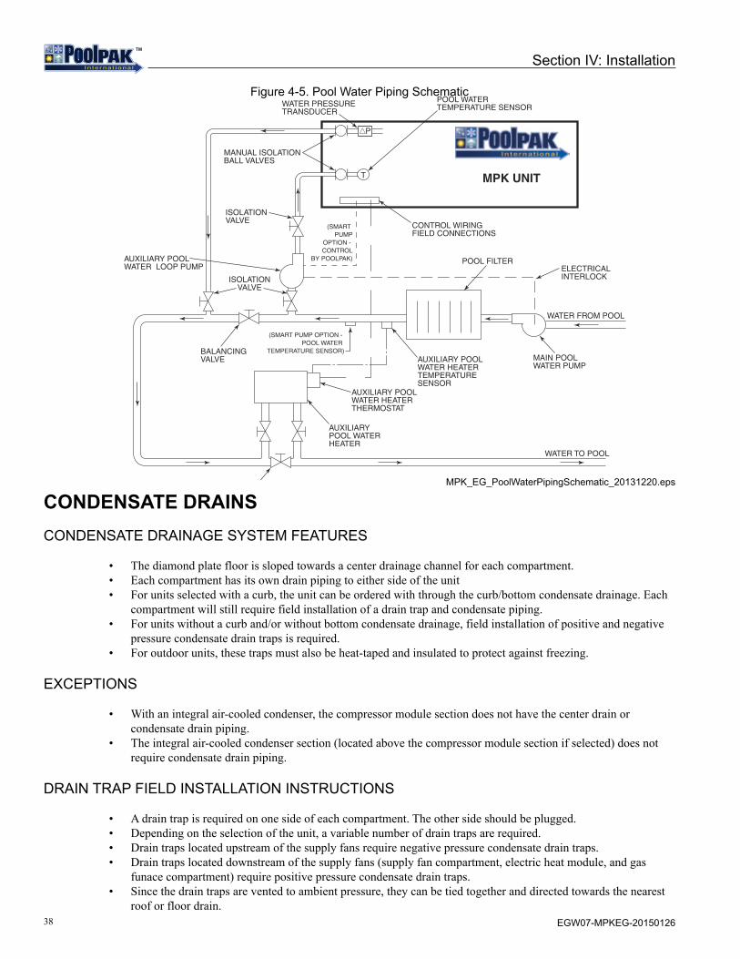
38 EGW07-MPKEG-20150126
TMTM
Section IV: Installation
Figure 4-5. Pool Water Piping Schematic
MPK_EG_PoolWaterPipingSchematic_20131220.eps
CONDENSATE DRAINSCONDENSATE DRAINAGE SYSTEM FEATURES
• The diamond plate floor is sloped towards a center drainage channel for each compartment.• Each compartment has its own drain piping to either side of the unit• For units selected with a curb, the unit can be ordered with through the curb/bottom condensate drainage. Each
compartment will still require field installation of a drain trap and condensate piping.• For units without a curb and/or without bottom condensate drainage, field installation of positive and negative
pressure condensate drain traps is required.• For outdoor units, these traps must also be heat-taped and insulated to protect against freezing.
EXCEPTIONS
• With an integral air-cooled condenser, the compressor module section does not have the center drain or condensate drain piping.
• The integral air-cooled condenser section (located above the compressor module section if selected) does not require condensate drain piping.
DRAIN TRAP FIELD INSTALLATION INSTRUCTIONS
• A drain trap is required on one side of each compartment. The other side should be plugged.• Depending on the selection of the unit, a variable number of drain traps are required.• Drain traps located upstream of the supply fans require negative pressure condensate drain traps.• Drain traps located downstream of the supply fans (supply fan compartment, electric heat module, and gas
funace compartment) require positive pressure condensate drain traps.• Since the drain traps are vented to ambient pressure, they can be tied together and directed towards the nearest
roof or floor drain.
WATER PRESSURETRANSDUCER
MANUAL ISOLATIONBALL VALVES
BALANCINGVALVE
BALANCINGVALVE
ISOLATIONVALVE
AUXILIARY POOLWATER LOOP PUMP
ISOLATIONVALVE
ELECTRICALINTERLOCK
CONTROL WIRINGFIELD CONNECTIONS
(SMART PUMP
OPTION - CONTROL
BY POOLPAK)
(SMART PUMP OPTION - POOL WATER
TEMPERATURE SENSOR)
T
P
AUXILIARY POOLWATER HEATERTEMPERATURESENSOR
AUXILIARY POOLWATER HEATERTHERMOSTAT
AUXILIARYPOOL WATERHEATER
POOL FILTER
WATER FROM POOL
WATER TO POOL
MAIN POOLWATER PUMP
POOL WATERTEMPERATURE SENSOR
MPK UNIT

39EGW07-MPKEG-20150126
TMTM
Section IV: Installation
• See below illustrations for more detail on the sizing of the negative and positive pressure condensate drain traps.
REQUIRED MATERIALS
• Schedule 40 (minimum) PVC plastic pipe, elbows, tees, and a removable cap for a cleanout.• For outdoor units, wrap drain lines and trap with electric heat tape (follow manufacturer’s instructions)
controlled by an automatic thermostat set at a minimum of 35F to protect against freezing.• For outdoor units, insulate all external condensate piping. Insulation must be sealed at all seams.
For additional questions or concerns regarding installation of condensate drains, please contact PoolPak™ Service.
NOTEPower for heat tape must be supplied external to the PoolPak™ unit.
Figure 4-6. Negative Pressure Condensate Drain Piping Cross Section
MPK_EG_NegPressCondPiping_20131210.eps
Figure 4-7. Positive Pressure Condensate Drain Piping Cross Section
MPK_EG_PosPressCondPiping_20131206.eps
UNIT BASE
MINIMUM SCHEDULE 40 PVC
REMOVABLECLEANOUT
OPEN TEEFOR VENT
NOTE: NOT TO SCALE
MPK UNIT
PLUG THEUNUSEDCONNECTIONWITH SUITABLEPVC PLUG
1
2
4 INCHES MINIMUM OR MAX NEGATIVE STATICPRESSURE (INCHES W.C.) + 1 INCH
2 INCHES MINIMUM OR 1/2
1
12
UNIT BASE
NOTE: NOT TO SCALE
1/2 INCH MINIMUM
MAX POSITIVE STATIC PRESSURE (INCHES W.C.) + 1/2 INCH MINIMUM
MINIMUM SCHEDULE 40 PVC
REMOVABLECLEANOUTOPEN TEE
FOR VENT
1
1
2
2
PLUG THEUNUSEDCONNECTIONWITH SUITABLEPVC PLUG
MPK UNIT

40 EGW07-MPKEG-20150126
TMTM
Section IV: Installation
REMOTE AIR COOLED CONDENSERSPACE AND LOCATION REQUIREMENTS
The most important consideration which must be taken into account when deciding upon the locations of air-cooled equipment is the provision for a supply of ambient air to the condenser, and removal of heated air from the condenser area. Where this essential requirement is not adhered to, it will result in higher head pressures, which cause poor operation and possible eventual failure of equipment. Units must not be located in the vicinity of steam, hot air, or fume exhausts.
Another consideration which must be taken is that the unit should be mounted away from noise sensitive spaces and must have adequate support to avoid vibration and noise transmission into the building. Units should be mounted over corridors, utility areas, rest rooms, and other auxiliary areas where high levels of sound are not an important factor. Sound and structural consultants should be retained for recommendations. Walls or Obstructions
The unit should be located so that air may circulate freely and not be re-circulated. For proper air flow and access all sides of the units should be a minimum of “W” away from any wall or obstruction (see Figure 4-8, Figure 4-9, Figure 4-10, or Figure 4-11). It is preferred that this distance be increased whenever possible. Care should be taken to see that ample room is left for maintenance work through access doors and panels. Overhead obstructions are not permitted. When the unit is in an area where it is enclosed by three walls, the unit must be installed as indicated for units in a pit.
Figure 4-8. Remote ACC Installation Around Walls or Obstructions
ALL_WallsorObstructions_20131111.eps
MIN.W*
AIR FLOW
* W”=Total width of the condenser”

41EGW07-MPKEG-20150126
TMTM
Section IV: Installation
Multiple Units
For units placed side by side, the minimum distance between units is the width of the largest unit. If units are placed end to end, the minimum distance between the units is 4 feet.
Figure 4-9. Remote ACC Installation When Installing Multiple Units
ALL_MultipleUnits_20131111.eps
Units in Pits
The top of the unit should be level with the top of the pit and side distances increased to “2W”. If the top of the units isnot level with the top of the pit, discharge cones or stacks must be used to raise discharge air to the top of the pit. This is a minimum requirement
Figure 4-10. Remote ACC Installation When Installing Units in Pits
ALL_UnitsinPits_20131111.eps
Decorative Fences
Fences must have 50% free area, with 1 foot undercut, a “W” minimum clearance, and must not exceed the tops of the unit. If these requirements are not met, the unit must be installed as indicated for “Units in Pits”.
Figure 4-11. Remote ACC Installation When Installing Units Near Decorative Fences
ALL_DecorativeFences_20131111.eps
MIN.
* W”=Total width of the condenser”
W*
AIR FLOWAIR FLOW
* W”=Total width of the condenser”
MIN. MIN.
AIRFLOW
2W*2W*
STACK(BY OTHERSIF SUPPLIED) 10’ MAX.
* W”=Total width of the condenser”
MIN.1” MIN. MIN.
AIR FLOWW* W*

42 EGW07-MPKEG-20150126
TMTM
Section IV: Installation
FIELD INSTALLED PIPING
Installation of the outdoor air-cooled condenser should only be done by a qualified refrigeration mechanic familiar withthis type of work. Many service problems can be avoided by taking adequate precautions to provide an internally cleanand dry system and by using procedures and materials that conform to established standards.
Piping Guidelines
The following piping recommendations are intended for use as a general guide. For more complete information, refer to the latest ASHRAE Handbook.
Materials:• Use clean, dehydrated, refrigeration-grade copper tubing for all refrigerant lines. Hard drawn tubing should be
used where no appreciable amount of bending around pipes or obstructions is necessary. If soft copper tubing must be used care should be taken to avoid sharp bends which may cause restrictions and excessive refrigerant pressure drops.
• Use long radius elbows wherever possible with one exception - short radius elbows should be used for any traps in the hot gas riser.
• Braze all copper to copper joints with a phosphorus-copper alloy material such as Silfos 5 or equivalent. Do not use soft solder.
• During brazing operations flow an inert gas, such as nitrogen, through the lines to prevent internal oxidation scaling and contamination.
• Support refrigeration lines at intervals with suitable hangers, brackets or clamps.• Pack glass fiber insulation and a sealing material around refrigerant lines, where they penetrate a wall, to reduce
vibration and to retain some flexibility.• The liquid line and discharge line should not be in contact with one another. If the installing contractor must tie
these lines together because of an installation requirement, the contractor must insulate them from each other to prevent heat transfer. Because the discharge line is hot during system operation, precautions should be taken to avoid personnel injury.
• PoolPak™ units do not utilize compressors with unloading stages. Consequently, double hot gas risers are not needed for reduced load conditions as refrigerant flow rates will not fall below minimum velocities necessary to carry oil up through the discharge line.
• A field provided, field installed liquid line filter-drier is required in the field piping adjacent to the PoolPak™ unit
Sizing:• The lines must be sized and routed so that oil is carried through the system. Using smaller lines than
recommended will give excessive pressure drops resulting in reduced capacity and increased power consumption. Oversizing lines could result in an oil flow problem within the system and possible compressor damage.
• Excessive pressure drops in the liquid line may cause flashing of the refrigerant and a loss of a liquid seal at the expansion valve inlet. A reduction in capacity may then occur because the presence of gaseous refrigerant will partially block the expansion valve. Proper sizing and charging of the lineset will prevent this problem.
• Discharge lines should be designed to prevent condensed refrigerant and oil from draining back to the compressor during OFF cycles. Use the following guidelines:• The highest point in the discharge line should be above the highest point in the condenser coil.• The hot gas line should loop toward the floor if the condenser is located above the PoolPak™ unit, especially
if the hot gas riser is long.• For refrigerant line sizing for an Air Cooled Condenser (ACC) where the lineset length is less than 100 feet or
the ACC location is less than 50 feet higher or 20 feet lower than the unit, use the below Table 4-1.• ACC line lengths beyond the above limits will void warranty unless written approval is obtained from the
factory PRIOR to installation and startup.

43EGW07-MPKEG-20150126
TMTM
Section IV: Installation
Table 4-1. Pipe Sizes for Remote Refrigerant Condensers
WARNING!Above chart is for lineset length less than 100 ft and ACC located less than 50ft above unit or 20ft below unit. Failures due to a piping layout not within these limits nor receiving prior PoolPak™
Factory approval will not be covered under PoolPak™ warranty.
Figure 4-12. Remote ACC Above Unit
REMOTE AIR-COOLED OR WATER-COOLED
CONDENSER
LI Q UI D LINE
*
*
P oo l Pool Internat ional
TOP OF CONDENSER COIL
HOT GAS LINE
LINE SIZED BALL VALVE
* EVACUATION AND CHARGING PORTS
REPLACEABLE CORE FILTER DRIER(Sporlan C-96”N” Series shell. “N” is dependent on liquid line size)
PPK_EG_GR_ACCAboveUnit.eps
Hot Gas Lines2
Liquid Lines2
Horizontal Run Vertical RiserModel1 Circuit 1 Circuit 2 Circuit 3 Circuit 1 Circuit 2 Circuit 3 Circuit 1 Circuit 2 Circuit 3
030 1-3/8 1-3/8 - 1-3/8 1-3/8 - 7/8 7/8 -035 1-3/8 1-3/8 - 1-3/8 1-3/8 - 7/8 1-1/8 -040 1-3/8 1-5/8 - 1-3/8 1-5/8 - 7/8 1-1/8 -045 1-3/8 1-5/8 - 1-3/8 1-5/8 - 1-1/8 1-1/8 -050 1-3/8 1-5/8 - 1-3/8 1-5/8 - 1-1/8 1-3/8 -060 1-3/8 1-3/8 1-3/8 1-3/8 1-3/8 1-3/8 1-1/8 1-1/8 1-1/8070 1-3/8 1-5/8 1-5/8 1-3/8 1-5/8 1-5/8 1-1/8 1-1/8 1-1/8080 1-5/8 1-5/8 1-5/8 1-5/8 1-5/8 1-5/8 1-1/8 1-1/8 1-3/8090 1-5/8 1-5/8 1-5/8 1-5/8 1-5/8 1-5/8 1-1/8 1-3/8 1-3/8
1 Models 060, 070, 080, and 090 have 3 refrigeration circuits piped independently.2 All pipe diameters are nominal OD inch sizes. Use only certified refrigeration tubing.

44 EGW07-MPKEG-20150126
TMTM
Section IV: Installation
Refrigerant and Oil Charging:• PoolPak™ units are shipped with the required charge for self contained operation only. The remote ACC option
does NOT provide the refrigerant charge or oil required for the ACC and line sets. • Refer to the below remote ACC and line size charging charts to calculate the additional charge required. • For the additional oil required, multiply 2% by the total additional refrigerant charge (ACC and lineset length).
For Bitzer compressors, use Idemitsu FVC32D PVE Oil.• Contact Factory for additional help or verifying the additional refrigerant charge.
Table 4-2. Remote ACC Refrigerant (R-410A) Charge
Table 4-3. Refrigerant (R-410A) Charge for Different Line Sizes(based on 120oF saturated condensing temperature)
WARNING!Above chart is for lineset length less than 100 ft and ACC located less than 50ft above unit or 20ft below unit. Failures due to a piping layout not within these limits nor receiving prior PoolPak™
Factory approval will not be covered under PoolPak™ warranty.
ACC Model # Circuit #1 (lbs) Circuit #2 (lbs) Circuit #3 (lbs)MAC0532 22 22 -MAC0602 22 22 -MAC0682 22 29 -MAC0742 22 29 -MAC0842 22 34 -MAC1003 22 22 22MAC1163 22 29 29MAC1353 29 29 34MAC1483 29 34 34
Tube OD (inches)
Wall thickness (inches) Tubing Type Discharge
(lb/ft)Liquid (lb/ft)
7/8 0.045 L 0.021 0.1921 1/8 0.05 L 0.036 0.3271 3/8 0.055 L 0.055 0.4991 5/8 0.072 K 0.076 0.684
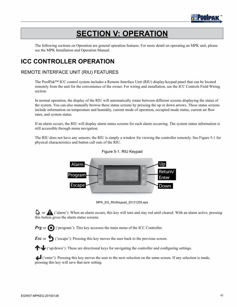
45EGW07-MPKEG-20150126
TMTM
SECTION V: OPERATIONThe following sections on Operation are general operation features. For more detail on operating an MPK unit, please see the MPK Installation and Operation Manual.
ICC CONTROLLER OPERATIONREMOTE INTERFACE UNIT (RIU) FEATURES
The PoolPak™ ICC control system includes a Remote Interface Unit (RIU) display/keypad panel that can be located remotely from the unit for the convenience of the owner. For wiring and installation, see the ICC Controls Field Wiring section.
In normal operation, the display of the RIU will automatically rotate between different screens displaying the status of the system. You can also manually browse these status screens by pressing the up or down arrows. These status screens include information on temperature and humidity, current mode of operation, occupied mode status, current air flow rates, and system status.
If an alarm occurs, the RIU will display alarm status screens for each alarm occurring. The system status information is still accessible through menu navigation.
The RIU does not have any sensors; the RIU is simply a window for viewing the controller remotely. See Figure 5-1 for physical characteristics and button call outs of the RIU.
Figure 5-1. RIU Keypad
MPK_EG_RIUKeypad_20131205.eps
or (‘alarm’): When an alarm occurs, this key will turn and stay red until cleared. With an alarm active, pressing this button gives the alarm status screens.
Prg or (‘program’): This key accesses the main menu of the ICC Controller.
Esc or (‘escape’): Pressing this key moves the user back to the previous screen.
/ (‘up/down’): These are directional keys for navigating the controller and configuring settings.
(‘enter’): Pressing this key moves the user to the next selection on the same screen. If any selection is made, pressing this key will save that new setting.
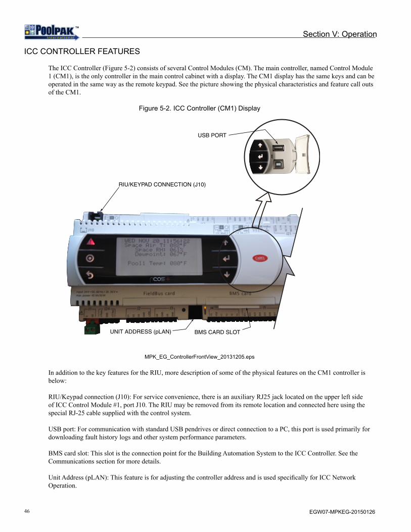
46 EGW07-MPKEG-20150126
TMTM
Section V: Operation
ICC CONTROLLER FEATURES
The ICC Controller (Figure 5-2) consists of several Control Modules (CM). The main controller, named Control Module 1 (CM1), is the only controller in the main control cabinet with a display. The CM1 display has the same keys and can be operated in the same way as the remote keypad. See the picture showing the physical characteristics and feature call outs of the CM1.
Figure 5-2. ICC Controller (CM1) Display
USB PORT
RIU/KEYPAD CONNECTION (J10)
UNIT ADDRESS (pLAN) BMS CARD SLOT
MPK_EG_ControllerFrontView_20131205.eps
In addition to the key features for the RIU, more description of some of the physical features on the CM1 controller is below:
RIU/Keypad connection (J10): For service convenience, there is an auxiliary RJ25 jack located on the upper left side of ICC Control Module #1, port J10. The RIU may be removed from its remote location and connected here using the special RJ-25 cable supplied with the control system.
USB port: For communication with standard USB pendrives or direct connection to a PC, this port is used primarily for downloading fault history logs and other system performance parameters.
BMS card slot: This slot is the connection point for the Building Automation System to the ICC Controller. See the Communications section for more details.
Unit Address (pLAN): This feature is for adjusting the controller address and is used specifically for ICC Network Operation.

47EGW07-MPKEG-20150126
TMTM
CONTROLLER NAVIGATION
In navigating the keypad, the user has access to: Status Screens, Set Points, Schedules, Detailed Status, and Service.
Status Screens and Detailed Status both contain read-only indicators of the operation of the unit. For example, these describe room conditions, airflow conditions, unit status, stages of heat or cooling requested, stages of aux heat or aux cool available, and fan motor status.
By selecting Set Points, the following set points can be adjusted: space temperature, space humidity, pool water temperature 1, minimum outside air amount, and maximum outside air amount. The RIU can be configured with a password on Set Point changes for additional security. The Set Point location also has a Timed Purge function that allows the user to override the controls and put the unit into purge mode for a set time period.
The Schedules menu contains the setup screens for an Occupied/Unoccupied schedule, a Purge schedule, and an Event Mode Schedule. Each of these schedules has a total of 28 events that can be configured. Keep in mind that each schedule requires two events to be scheduled, a START and an END event. This allows for 14 unique schedules to be configured per week.
The Service menu contains the following password protected service items: Input/Output Configuration, History, Unit Configuration, Manual Mode, and Utilities. These menus are used to initially startup and configure the PoolPak™ unit and diagnose any potential problems.
For specific details on controller navigation, see the Operation section of the MPK Installation and Operation Manual.
FAULT CONDITION
When properly installed according to the instructions in this manual, the PoolPak™ ICC control system will perform as designed and will provide a pool environment that is both comfortable and cost effective. However, in the unlikely event that the system does not function properly, the ICC has many features that will help a service technician resolve the issue.
The PoolPak™ has numerous safety devices designed to protect the system from failures. The MPK unit can display the following alarms:
• Coil Freeze Warning• Fire Trip Active• Smoke Purge Active• Exhaust Fan Not Running• Purge Fan Not Running• Supply Fan Not Running• Exhaust VFD Fault• Purge VFD Fault• Supply VFD Fault• Aux Air Heating System Failure• Aux Air Cooling System Failure
Each compressor module also can generate the following alarms:
• Compressor Module Locked Out• Compressor Module High Pressure (Refrigerant)• Compressor Module High Motor Temp• Compressor Module Low Pressure (Refrigerant)• Compressor Module Discharge Pressure Transducer Failure• Compressor Module Suction Pressure Transducer Failure
Section V: Operation

48 EGW07-MPKEG-20150126
TMTM
• Compressor Module Current Transducer Failure • Compressor Module Suction Temp Sensor Failure• Compressor Module Liquid Temp Sensor Failure
The compressor and/or fan motors will be shut down when a fire control system alerts the ICC that a fire trip or smoke purge mode of operation is required.
Whenever a fault condition occurs, the alarm button on the RIU and CM1 will glow red and the displays will show the fault condition and a recommended course of action. After 10 compressor-related faults occur, the affected compressor module will be locked out for protection. Repetitive faults can cause compressor motor failure. When a compressor fault condition exists, it must be diagnosed and corrected before resetting the system.
After a fault has been eliminated, the control panel alarm light will remain lit. However, the alarm will no longer be shown in the normal status screen rotation. Pressing the alarm key will show any faults that have occurred since the alarm light was reset.
ALARM RESET
To reset the alarm on the RIU, press and Esc at the same time. CM1/compressor module: and . If there are currently no active fault conditions, the alarm light will go off. The alarm contact closure output of the controller operates in conjunction with the alarm light on the RIU and CM1.
COMMUNICATIONSBUILDING AUTOMATION SYSTEM (BAS) CONNECTION
The PoolPak™ ICC control system provides four optional Building Automation System (BAS) connection types: LonWorks, ModBus, BACnet/IP, and BACnet MS/TP. These standard BAS connections are attached to the building system at the T16 terminal block.
The BACnet/IP option includes the Remote Access Package feature. When the ICC controller is equipped with the BACnet/IP interface, RJ45 connection is made to the serial card port on control module CM1. The controller has a second card port and can run a separate BAS in parallel with RAP.
See the respective BAS Installation & Operation guide on the PoolPak™ website for more details, www.poolpak.com.
VIRTUAL-TECH™ PLUS - REMOTE ACCESS PACKAGE (RAP)
Virtual-Tech™ Plus is a stand-alone communication system. The system runs an embedded web server over an IEEE 802.3 10/100 BaseT Ethernet. The web server operates on TCP/IP port 80, the Internet default for web traffic. The web server port is configurable. The RAP can be accessed from either an internal network or the Internet. IP addresses and ports must be routed to the RAP for access via the Internet. Virtual Private Network Connections (VPN) to the RAP will not be supported.
RAP requires the BACnet I/P BAS interface. If selected, this card is factory configured and installed in the BMS card slot. This card has a built in web server that exports operating system data and fault information to an external web-page. This allows the factory to data log system variables remotely.
Ethernet 10/100 Direct Connection
When the ICC controller is equipped with the BACnet/IP interface, RJ45 connection is made to the serial card port on control module CM1.
Section V: Operation

49EGW07-MPKEG-20150126
TMTM
Send Emails – Alerts for Alarms
When a critical alarm occurs with the PoolPak™ unit, the RAP will send an email to the PoolPak™ Service Department, via a mail server maintained by PoolPak™. The RAP will create no other network traffic.
AIRFLOW BALANCINGOVERVIEW
Airflow balancing is an important part of operation and unit commissioning. The design conditions especially for static pressures are not expected to meet actual conditions and thus adjustments will need to be made. The MPK unit is able to maintain a self-balancing condition but must first be properly configured.
GUIDELINES FOR PERFORMING A PROPER AIRFLOW BALANCE
PoolPak™ International recommends that the air balance be performed by an independent air balancing contractor. In addition to supplying the proper tools, a good air balancing contractor will follow the below guidelines:
• Supply a report with all the below recorded design and actual data.• Take a representative traverse of the duct to attain good readings for supply, return, exhaust, and outdoor air
flows. This may require additional traverses for a particular air inlet depending on the duct installation.• Record the following design and actual data for all supply, return, exhaust, and outdoor air flows:
• Air flow rates• Static pressure readings• Fan speeds and power consumption (fan amps)• All motorized damper set points for each set of data
• Record the above data at both the minimum and maximum operating modes:• Purge mode (or 100% outside air)• Unoccupied mode (or 0% outside air)
PoolPak requires the above information as complete as possible. This information is needed to adequately configure the MPK unit to attain the desired ventilation.
CONTROLLER ADJUSTMENTS
The controller airflow parameters can be adjusted to properly balance the airflow entering and leaving the MPK unit. PoolPak™ recommends that this procedure be done at unit startup and therefore a full procedure is part of the PoolPak™ MPK Start Up Procedure.
TROUBLESHOOTINGOVERVIEW
The below section is a brief description of general features of the PoolPak™ ICC controller that can be used in troubleshooting fault conditions that arise with the PoolPak™ unit.
SYSTEM STATUS INFORMATION
To aid in troubleshooting, the ICC controller contains all of the pertinent system status information to let the user know the current operation status of the PoolPak™ unit. Many alarms can be diagnosed and resolved just by reviewing the system status information.
Section V: Operation

50 EGW07-MPKEG-20150126
TMTM
FAULT HISTORY LOG
To assist in troubleshooting, the ICC controller maintains a rolling log of the last 100 faults. In addition, each compressor module also maintains a rolling log of the last 100 faults occurring at that compressor module.
The fault history log is the “History” option as selected in the “Service” menu.
Each fault captures the following information in the main controller memory:
• Date and Time of Occurrence• Fault Code• Return Air Temp• Return Air RH• Mixing Box Percent Open• Aux Heat Stages Active• Aux Cool Stages Active• Outside Air Temp• Outside Air RH• Supply Air Temp• Supply Motor Speed• Exhaust Motor Speed• Purge Motor Speed• Outside Air Damper Actual Position• Recirculation Damper Actual Position• Evap Bypass Damper Actual Position• Supply Air CFM• Exhaust Air CFM• Purge Air CFM• Outside Air CFM• Supply Fan Current• Exhaust Fan Current• Purge Fan Current• Pool 1 Water Temp• Pool 2 Water Temp
Each fault captures the following information in the compressor module memory:
• Date and Time of Occurrence• Fault Code• Status• Operating Mode• Requested Operating Mode• Active Fault Code• Current• Discharge Pressure• Liquid Temperature• Suction Pressure• Suction Temperature
In addition to the above, each fault in the log is assigned a number from 1 to 100. Fault number 1 is the most recent and 100 is the oldest. Use the and arrow keys to cycle through the faults one at a time. To view additional information for each fault, use the key to cycle through the available screens of stored information.
For more information on the fault history log, see the MPK Installation and Operation Manual.
Section V: Operation

51EGW07-MPKEG-20150126
TMTM
MANUAL MODE
The ICC controller contains an enhanced manual control mode for improved troubleshooting efficiency. Manual Mode is located in the Service menu of the controller. Navigating the manual mode menus is the best method to troubleshoot complex issues with system performance, digital outputs, and analog outputs.
Refer to the MPK Installation and Operation Manual for more information.
DIGITAL AND ANALOG INPUT INFORMATION
In the Input/Output Configuration (I/O Config) under the Service menu of the controller, the status and configuration of digital and analog inputs can be viewed. This information can be helpful to determine if an input is correctly configured to be received by the ICC controller.
Digital Input
Each digital input of the ICC controller can be viewed in the Service menu of the controller. These screens give you a read-only indication of the status of these inputs. These inputs can be useful in confirming whether or not the ICC controller is receiving an input from a certain component (ie. fire alarm system, smoke detectors, occupied override, manual purge mode, remote exhaust fan status, freezestat, or remote AC proof).
Analog Input
In addition to the digital and analog outputs, each analog input of the ICC controller can be configured or adjusted. This ability is especially important when calibrating sensors or in the event of a failed sensor in order to continue normal operation.
DIGITAL AND ANALOG OUTPUT CONFIGURATION
Input/Output Configuration (I/O Config) is a selectable option in the Service menu of the Controller. With this function, the qualified HVAC service technician has access to Digitial Outputs and Analog Outputs.
Digital Output
Each digital output of the ICC controller may be controlled individually by setting the corresponding parameter to one of three possible values: AUTO, ON, or OFF. A setting of AUTO gives control of the digital output relay to the software in the ICC. ON will force the output relay to energize regardless of the status requested by the software. OFF will force the output relay to de-energize regardless of the status requested by the software.
The digital outputs found in this menu are solenoid valves, fan start signals, compressor run signals, auxiliary heat run signals, smart pump enable, and more.
Analog Output
Each analog output of the ICC controller may be controlled individually by setting the corresponding parameter. This is helpful determining functionality of auxiliary control valves or dampers.
Section V: Operation
52 EGW07-MPKEG-20150126
TMTM
STARTUP & WARRANTYPRE-STARTUP
After receiving the PoolPak™ unit, there are several tasks to complete before scheduling the factory startup. PoolPak™ Service maintains and provides a checklist of these activities that they require in order to schedule startup.
This checklist provides additional confirmation of the proper installation of the unit and any field installed components. These items include but are not limited to field wiring for remote ACC/WCC, field wiring for field installed sensors, refrigerant piping for remote ACC/WCC, and water piping for pool water and remote WCC applications.
This checklist determines that the space conditions and unit condition will be suitable for startup. If the checklist is completed satisfactorily, startup and owner training can be accomplished in a single day.
This pre-startup checklist will be given at the time of order acknowledgement. It can also be found in the PoolPak™ website, www.poolpak.com, under the Start-up and Warranty section of the Parts & Service Downloads page.
STARTUP
PoolPak™ Service requires a minimum of 2 weeks notice to allow adequate time to schedule startup. This 2 weeks notice includes a completed pre-startup checklist as described above. If Startup is required within the first month of shipment, special arrangements must be made with PoolPak™ Accounting Department at the time of Order Acknowledgement.
In instances where the equipment start-up will be delayed, a Delayed Startup Warranty Extension may be purchased in one-month increments for up to an additional 12 months. This delayed startup can be purchased any time before the actual startup. Contact PoolPak™ Service at [email protected] to apply.
If special access is required to access the site, PoolPak™ service must be made aware of special access requirements at the time of 2 week notice. PoolPak™ Service will also ask for site contact information to provide to the startup technician.
All MPK units ship without the ICC CM1 controller. This is done to ensure a proper startup of the equipment before regular operation.
The startup technician will bring the ICC CM1 controller, the Startup Procedure document, and any other Startup materials to the jobsite. The startup technician is expected to perform only the startup procedures as described in the Startup Procedure document. Field supplied components, such as auxiliary duct heaters or remote condensers, are expected to be installed and started up by the owner per the manufacturer’s instructions.
All PoolPak™ units require proper startup by a PoolPak™ authorized service technician. PoolPak™ service will arrange this startup with the previously approved and trained service technicians. For a list of current authorized service technicians in your area, please visit the Service Locator page of the PoolPak™ website, www.poolpak.com.
If there are additional service companies that you would like to recommend to become authorized providers, please contact PoolPak™ Service at [email protected]. PoolPak™ Service holds a Service Training School three times per year. See the Service section of our poolpak website for more details.
Section V: Operation

53EGW07-MPKEG-20150126
TMTM
OWNER TRAINING
As a part of the Startup procedure, the poolpak technician will also provide a brief orientation on the PoolPak™ unit, keypad operation, and recommended maintenance. In this presentation, he will refer to the MPK Installation and Operation Manual as a guide.
It is the responsibility of the facility or sales rep to schedule maintenance personnel and other interested parties to attend this training. The owner training typically occurs at the end of the Startup day. If necessary, owner training can be scheduled with the technician for a later day. Keep in mind that a second trip may require additional compensation beyond a single day startup allowance.
WARRANTY
PoolPak™ maintains a standard labor and parts warranty on MPK units. For a description of this standard warranty, please visit the Parts & Service Downloads section of our website, www.poolpak.com. Warranty information is in the Start-Up & Warranty section.
All parts and labor warranty claims require prior written authorization of PoolPak™ Service department to be covered under warranty.
PoolPak™ units require regular care and maintenance. Component failure due to poor pool chemistry, maintenance neglect, or customer abuse will be denied warranty coverage.
For instances where pool chemistry is a suspected factor in component failure, PoolPak™ Service may request the facilities’ pool chemistry logs.
The all copper and Hycor® Blue coil warranties are contingent on the pool water free chlorine level being maintained in the 1.0 ppm to 3.0 ppm range and the chloramine level not exceeding 0.2 ppm.
Section V: Operation

54 EGW07-MPKEG-20150126
TMTM
MAINTENANCEOVERVIEW
Periodic routine maintenance will promote extended equipment life. While PoolPak™ units use components that are usually maintenance free and do not require service, a regular check-up could result in noticing possible problems before they develop into major problems.
DAILY MAINTENANCE
PROPER MAINTENANCE OF YOUR POOL WATER CHEMISTRY ON A DAILY BASIS IS IMPORTANT TO PROTECT YOUR WARRANTY RIGHTS.
1. Daily logging of pool water chemistry is typically required by local state health codes and may be requested by PoolPak™ in order to determine proper pool water chemistry maintenance. These logs should include both free chlorine and total chlorine measurements at a minimum.
2. PoolPak™ International strongly recommends following the below National Spa and Pool Institute standards.
Table 5-1. Pool Water Chemistry
For more information on pool water chemistry, see the PoolPak™ Educational Library article “Indoor Pool Water Chemistry”.
MONTHLY MAINTENANCE
NOTETo prevent personal injury, disconnect all electrical power to the unit prior to performing any of the following maintenance procedures.
Perform the following on a monthly basis:
1. AIR FILTERS: Check and replace as necessary. 2. Direct Drive Plenum Fans & Motors: Fan motor bearings are greased from the factory. DO NOT RE-GREASE FAN
MOTOR BEARINGS.3. COMPRESSOR OIL LEVEL: The ideal time for checking the oil level is during an extended period of operation
because there will be the least amount of refrigerant mixed with the oil. The compressor should have been in operation at least 1/2 hour. During the period of operation, the refrigerant will be pumped out of the oil until only the normal quantity remains. The compressor is equipped with an oil sight glass for checking oil level. The sight glass is
Pool SpaIdeal Min Max Ideal Min Max
Total Chlorine (ppm) 1.0 - 3.0 1 3 3.0 - 5.0 1 10Free Chlorine (ppm) 1.0 - 3.0 1 3 3.0 - 5.0 1 10Combined Chlorine (ppm) 0 0 0.3 0 0 0.3Bromine (ppm) if applicable 2.0 - 4.0 2 4 3.0 - 5.0 2 10pH 7.4 - 7.6 7.2 7.8 7.4 - 7.6 7.2 7.8Total Alkalinity (ppm) 80 - 100 80 180 80 - 100 60 180TDS (ppm) 1000 - 2000 300 3000 1000 - 2000 300 3000Calcium Hardness (ppm) 200 - 400 150 1000 200 - 400 150 1000Calcium Acid (ppm) 30 - 50 10 100 30 - 50 10 100
Section V: Operation

55EGW07-MPKEG-20150126
TMTM
located on the compressor shell. Oil should be added to the system by a qualified refrigerant service technician only. The oil level in the compressor is correct when oil is visible between the bottom and two-thirds of the sight glass.
4. REFRIGERANT CHARGE: Check the sight glasses located in the valve compartment on the end of the evaporator coil. When the refrigerant charge is correct, there should be no bubbles in the sight glasses. Intermittent bubbles are normal during the first 10 minutes of operation or following a change in operating mode.
5. CONDENSATE LINE: Ensure that it is free of obstructions. Always keep the condensate trap and lines free and clear. The PoolPak™ is capable of producing up to 60 gallons of condensate per hour.
6. UNIT INTERIOR/EXTERIOR: Check for torn insulation and repair if necessary. Check for scratches, nicks, rust, etc.
7. LOGBOOK: Check and record, in the logbook, the following actual operating values and the values read from the ICC controller display: • Space Temperature • Space Relative Humidity • Pool Water Temperature • Pool Water pH• Pool Water Free Chlorine• Pool Water Total Chlorine
8. DAMPER OPERATION: Ensure that dampers open and close fully without binding.
SEMI-ANNUAL MAINTENANCE
In addition to the Monthly Maintenance items, the following should be performed on a semi-annual basis:
Condenser coil cleaning: • PoolPak recommends that the finned surface of all integral condenser coils be cleaned approximately every six
months. More frequent cleaning may be required if extreme conditions cause clogging or fouling of air passages through the coil.
• Calgon Corporation’s CalClean 41352 (or equal) is acceptable for cleaning this unit.• The cleaning solution should be applied liberally to entering air and leaving air surfaces of the coil in accor
dance with the cleaning solution instructions.• For a unit specific coil cleaning procedure, please see the Maintenance Section under Service Downloads
on the PoolPak™ website, www.poolpak.com• Note: For non-coated copper coils, if you notice the coil surface turning green, you have a problem with pool
water chemistry. Address this root issue before seeking out more destructive coil cleaning solutions to remove the green from the coil.
ANNUAL MAINTENANCE
Perform the following on an annual basis:
1. All items listed under MONTHLY MAINTENANCE and SEMI-ANNUAL MAINTENANCE.2. COMPRESSOR AND REFRIGERATION SYSTEM: The compressor and refrigeration system should be inspected
annually by a qualified service technician. At minimum, the following items should be done: • Change and inspect the refrigerant filter drier (only if the system has been open). • Complete unit operation test including log entries. • Inspect fan motor bearings for excessive wear and replace if necessary. • General refrigeration system inspection for possible leaks, chafing between tubing, or other items detrimental to
operation. • Touch up scratches in the paint. • Check electrical connections for tightness including those in the compressor electrical box. • Clean debris and dirt from drain pans.
3. Variable Frequency Drives: Although typically seen as being maintenance free, there is some simple maintenance that can be done on a regular basis for VFD. The main goal of VFD maintenance is to keep it clean, keep it dry, and keep the connections tight. The below are the general PoolPak™ recommended tips for maintaining your VFD. These should be done annually by a qualified service technician.
Section V: Operation
56 EGW07-MPKEG-20150126
TMTM
• Check the control cabinet for any signs of moisture. If present, the cabinet joints should be re-sealed with Pool Pak approved silicone sealant.
• With the power off, spray dry, oil-free air over the heat sink fan(s) to remove dust.• With the power off, carefully remove the cover and visually check for any internal damaged components.• Use a dry dust-catching fabric (such as Swiffer® cloths) on the outside and inside of the VFD cabinet to remove
dust and debris. • With the cover carefully removed, check all electrical connections on each VFD for tightness. A simple “tug”
test should be sufficient. Tighten any loose connections. Re-install the cover.
For additional description of advanced VFD maintenance tips, see PoolPak™ Parts & Service article “How to Maintain a VFD”.
Section V: Operation
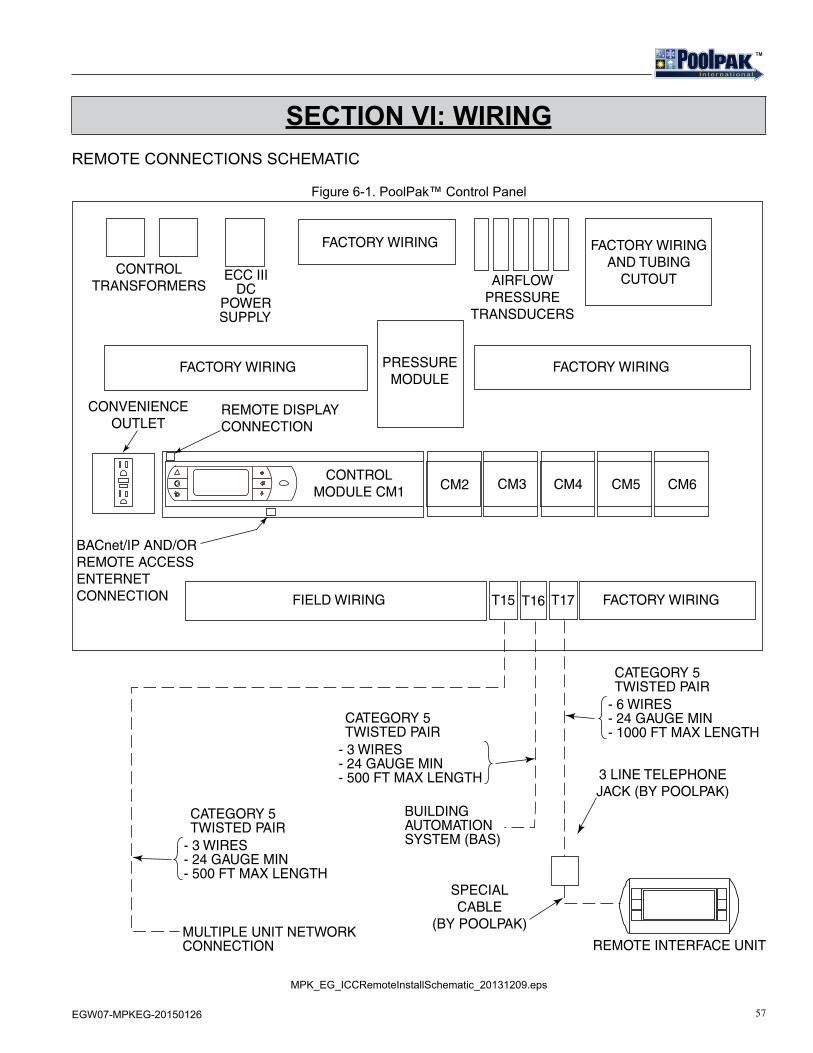
57EGW07-MPKEG-20150126
TMTM
SECTION VI: WIRINGREMOTE CONNECTIONS SCHEMATIC
Figure 6-1. PoolPak™ Control Panel
ECC IIIDC
POWERSUPPLY
FACTORY WIRING
FACTORY WIRING
FIELD WIRING
PRESSUREMODULE
REMOTE INTERFACE UNIT
SPECIALCABLE
(BY POOLPAK)
3 LINE TELEPHONEJACK (BY POOLPAK)
FACTORY WIRING
REMOTE DISPLAYCONNECTION
BACnet/IP AND/ORREMOTE ACCESSENTERNETCONNECTION
CONTROLMODULE CM1 CM2 CM3 CM4 CM5 CM6
FACTORY WIRING
FACTORY WIRINGAND TUBING
CUTOUTCONTROL
TRANSFORMERS AIRFLOWPRESSURE
TRANSDUCERS
T16T15 T17
- 3 WIRES- 24 GAUGE MIN- 500 FT MAX LENGTH
- 3 WIRES- 24 GAUGE MIN- 500 FT MAX LENGTH
- 6 WIRES- 24 GAUGE MIN- 1000 FT MAX LENGTH
BUILDINGAUTOMATIONSYSTEM (BAS)
MULTIPLE UNIT NETWORKCONNECTION
CATEGORY 5TWISTED PAIR
CATEGORY 5TWISTED PAIR
CATEGORY 5TWISTED PAIR
CONVENIENCEOUTLET
MPK_EG_ICCRemoteInstallSchematic_20131209.eps
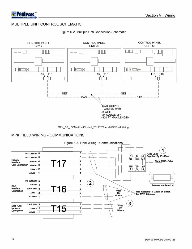
58 EGW07-MPKEG-20150126
TMTM
MULTIPLE UNIT CONTROL SCHEMATIC
Figure 6-2. Multiple Unti Connection Schematic
CONTROL PANELUNIT #1
CONTROL PANELUNIT #2
CONTROL PANELUNIT #3
T16
BAS BAS
T15
- 3 WIRES- 24 GAUGE MIN- 500 FT MAX LENGTH
T16T15 T16T15
CATEGORY 5TWISTED PAIR
NET NET
MPK_EG_ICCMultiUnitControl_20131209.epsMPK Field Wiring
MPK FIELD WIRING - COMMUNICATIONS
Figure 6-3. Field Wiring - Communications
3
2
1
Section VI: Wiring
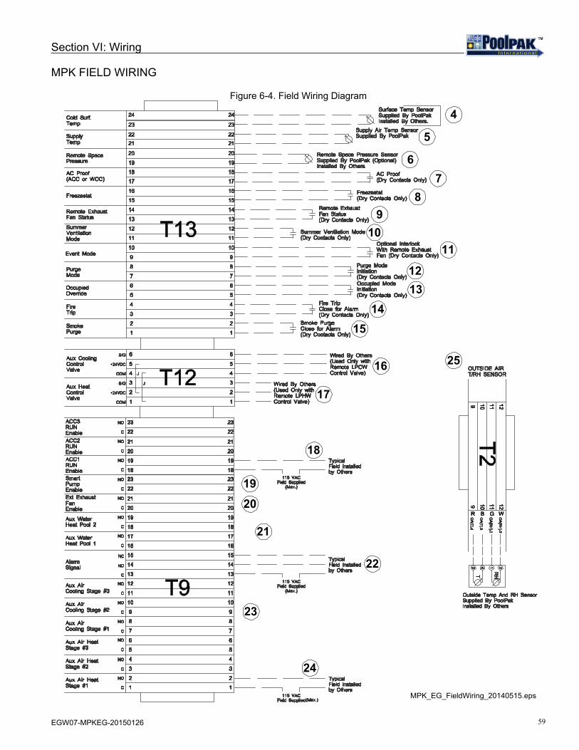
59EGW07-MPKEG-20150126
TMTM
MPK FIELD WIRING
Figure 6-4. Field Wiring Diagram
78
910
16
17
18
1920
21
22
23
24
25
1514
1312
11
4
5
6
Section VI: Wiring
MPK_EG_FieldWiring_20140515.eps

60 EGW07-MPKEG-20150126
TMTM
TMTM
3491 Industrial Drive . York, PA 17402 . USA . 800-959-7725 . Fax 717-757-5085for more information: www.poolpak.com
The Leader in Indoor Pool Dehumidification