pool, spa and solar control system - web solar supplies · pdf filepool, spa and solar control...
TRANSCRIPT

IMPORTANT SAFETY INSTRUCTIONSREAD AND FOLLOW ALL INSTRUCTIONSSAVE THESE INSTRUCTIONS
Pool, Spa and Solar Control System
Installation andUser’s Guide
SunTouch®

© 2010 Pentair Water Pool and Spa, Inc. All rights reserved
1620 Hawkins Ave., Sanford, NC 27330 • (919) 566-800010951 West Los Angeles Ave., Moorpark, CA 93021 • (805) 553-5000
SunTouch®, IntelliChlor®, IntelliFlo®, QuickTouch® , Sta-Rite®, MiniMax®, MasterTemp® and Pentair Water Pool andSpa® are trademarks and/or registered trademarks of Pentair Water Pool and Spa, Inc. and/or its affiliatedcompanies in the United States and/or other countries. Intermatic® is a registered trademark of Intermatic Inc.RayPak® is a registered trademark of Rheam Company. Hatward® is a registered trademark of Hayward IndustriesInc. Jandy® is a registered trademark of Jandy Pool Products Inc. Unless noted, names and brands of others thatmay be used in this document are not used to indicate an affiliation or endorsement between the proprietors ofthese names and brands and Pentair Water Pool and Spa, Inc. Those names and brands may be the trademarks orregistered trademarks of those parties or others.
P/N 520785 - Rev B 06/28/10

i
SunTouch Solar, Pool and Spa Control System Installation and User’s Guide
Contents
IMPORTANT SAFETY PRECAUTIONS ........................................................................................... iiiTechnical Support ............................................................................................................................ viSection 1: SunTouch Pool and Spa Control System Overview.................................................... 1
SunTouch Control System Overview ................................................................................................. 1 SunTouch Solar Mode .................................................................................................................. 1 SunTouch Pool/Spa Mode ............................................................................................................ 1SunTouch Control Panel ................................................................................................................... 2 SunTouch Control Buttons ............................................................................................................ 2SunTouch Main Status Screen (Solar Only mode) ............................................................................ 4SunTouch Solar Only System .......................................................................................................... 4Operating SunTouch in Solar Only Mode .......................................................................................... 5 Setting up SunTouch for Solar Only mode from Pool/Spa mode.................................................... 5 Adjusting the water temperature setting (Solar Only mode) .......................................................... 6 Solar Only Menus ........................................................................................................................ 6 Set Temperature ...................................................................................................................... 6 System Control ........................................................................................................................ 7 System Mode .......................................................................................................................... 7 Time Set .................................................................................................................................. 7 Start and Stop Temp Differentials ............................................................................................. 8 Solar Freeze protection ............................................................................................................ 8 Cleaner Freeze protection ........................................................................................................ 8 Air sensor ................................................................................................................................ 8 Freeze Protection in Solar Only mode .......................................................................................... 9Operating SunTouch in Pool/Spa mode (Shared Equipment) ............................................................. 9 Setting up SunTouch to Operate in Pool/Spa mode ...................................................................... 9 Adjusting the water temperature setting in Pool/Spa mode ........................................................... 9 Selecting the heat source ............................................................................................................ 10 SunTouch Main Status Screen (Pool/Spa mode - Shared Equipment) .......................................... 11 Pool/Spa Mode Menus (Shared Equipment) ................................................................................. 12Pool/Spa Mode Menus .................................................................................................................. 13 Circuit On/Off Menu (1/14) ............................................................................................................ 13 Heat Menu (2/14) ......................................................................................................................... 14 Pool Temperature and Heat Source settings ............................................................................ 14 Spa Temperature and Heat Source ........................................................................................... 15 HI-TEMP /LO-TEMP (Pool or Spa) Control Button .................................................................... 15 Manual Heat (Off/On) ............................................................................................................... 15 Delay Cancel Menu (3/14) ............................................................................................................ 16 Schedules Menu (4/14) ................................................................................................................ 17 Schedule your Spa or Pool ...................................................................................................... 18 Edit an existing program .......................................................................................................... 18 Delete a program ..................................................................................................................... 18 Clock Menu (5/14) ........................................................................................................................ 19 Solar Menu (6/14) ........................................................................................................................ 19 Valves Menu (7/14)....................................................................................................................... 21 Advanced Menu (8/14): Heater and Valve Delays .......................................................................... 22 Advanced Menu (8/14): Temp Units - F° / C° (Fahrenheit/Celsius) ................................................ 22 Advanced Menu (8/14): Calibrate water, air and solar sensors ...................................................... 23 Advanced Menu (8/14): Air Sensor Enable/Disable ....................................................................... 24 Advanced Menu (8/14): System Mode .......................................................................................... 24
ii
SunTouch Solar, Pool and Spa Control System Installation and User’s Guide
Contents
Advanced Menu (8/14): System Type ........................................................................................... 24 Advanced Menu (8/14): Reset Factory .......................................................................................... 25 Diagnostics Menu (9/14): Firmware Rev ....................................................................................... 25 Diagnostics Menu: Solar Temp ................................................................................................ 25 Diagnostics Menu: Self Test .................................................................................................... 25 Circuit Functions Menu (10/14) .................................................................................................... 26 Assigning Circuit Functions .......................................................................................................... 26 Freeze Protection .................................................................................................................... 26 Circuit Functions ..................................................................................................................... 26 Preset Circuit Functions .......................................................................................................... 27 Settings Menu (11/14): QuickTouch (QT4) Wireless Remote ........................................................ 28 Assign QT4 buttons ................................................................................................................. 28 Pump Menu (12/14) ..................................................................................................................... 28 Single speed filter pump .......................................................................................................... 28 Two-speed filter pump .............................................................................................................. 29 IntelliFlo VS pump .................................................................................................................. 30 Freeze Protection ............................................................................................................. 30 IntelliFlo VF pump................................................................................................................... 31IntelliChlor Menu (13/14) ................................................................................................................... 33IntelliChlor Menu (13/14): Status and Error Messages ...................................................................... 34Service Menu (14/14): Service, Timeout, Auto ................................................................................... 35SunTouch Main Status Screen (Pool/Spa Mode - Single Body System)............................................ 36High/Low Temperature Circuit Control (Single Body System) ............................................................ 36 HI-TEMP / LO-TEMP Circuit Controls ........................................................................................... 37 Setting up SunTouch to operate as a Single Body system ........................................................... 37 Pool/Spa Mode (Single Body of Water) Menus ............................................................................. 38
Section 2: Installation and Setup .................................................................................................. 39
SunTouch System Installation Steps Summary ................................................................................ 39 Required Tools ............................................................................................................................. 39SunTouch Solar Package Contents .................................................................................................. 40SunTouch Control System Contents ................................................................................................. 40 Replacement Parts ...................................................................................................................... 40 Optional Equipment ..................................................................................................................... 40 SunTouch System Overview ......................................................................................................... 40Plumbing Requirements ................................................................................................................... 43 Equipment Location ..................................................................................................................... 44 Solar Hydraulics System ............................................................................................................. 45
SunTouch Power Center High Voltage Connections .......................................................................... 46SunTouch Power Center Location ..................................................................................................... 46 Grounding and Bonding to the SunTouch Power Center ................................................................ 47 Preparing the SunTouch Power Center ......................................................................................... 46 Opening the front panel ................................................................................................................ 48Mounting the SunTouch Power Center .............................................................................................. 49 Removing Electrical Conduit Knockouts ....................................................................................... 50 Installing Conduit and Wire to the SunTouch Power Center .......................................................... 51Transformer Connections .................................................................................................................. 52 High Voltage Wiring ..................................................................................................................... 52SunTouch Motherboard Connections ................................................................................................ 53 Equipment Power ......................................................................................................................... 53 Accessing the SunTouch Motherboard ............................................................................................. 54Installing Auxiliary Relays ................................................................................................................. 55 Relay locations ............................................................................................................................ 55 Installing relays ............................................................................................................................ 55

iii
SunTouch Solar, Pool and Spa Control System Installation and User’s Guide
Installing Valve Actuators ................................................................................................................ 57 Adjusting the valve position .......................................................................................................... 57Installing and Connecting Temperature Sensors ............................................................................... 58 Water Temperature Sensor .......................................................................................................... 58 Ambient Air Temperature Sensor (for freeze protection) ................................................................ 58 Solar Temperature Sensor ............................................................................................................ 58Connecting SunTouch to a Gas Heater ............................................................................................. 59 Connecting to a standard heater .................................................................................................. 59 Connecting to a MiniMax®, MasterTemp® Gas Heater ................................................................ 59 Connecting to a Sta-Rite® Gas Heater ......................................................................................... 60 Connecting a Standard Heat Pump or Electric Heater .................................................................. 60SunTouch Solar System Installation ................................................................................................. 61 SunTouch Solar System Start-Up ................................................................................................. 61 Pool Cleaner Protection ............................................................................................................... 61 SunTouch Pool/Spa Controller System Start-Up ........................................................................... 62
Check Electronics ........................................................................................................................ 62 SunTouch System Test ................................................................................................................ 62 Testing the auxiliary relays .......................................................................................................... 62Setting up the SunTouch system for the first time (after equipment Installation) ................................ 63
Section 3: Troubleshooting ............................................................................................................ 65
Frequently Asked Questions (FAQ) .................................................................................................. 65 How do I setup a two-speed pump? .............................................................................................. 65 Can I switch the heater on and change the temperature from the spa? ......................................... 65 How do I switch on solar heating? ................................................................................................ 65SunTouch Error Messages ............................................................................................................... 66 Error Messages ........................................................................................................................... 66 Self Test Error Codes ................................................................................................................... 66 Error Code Table .......................................................................................................................... 66
Resetting the System Fuses ............................................................................................................ 66Problem Solving a Solar System ...................................................................................................... 67 SunTouch solar is not operating ................................................................................................... 67 Water flow to panels switch does not operate the valve actuator .................................................. 67 Checking The Temperature Sensors ............................................................................................. 67Testing the Solar System ................................................................................................................. 67 Air Sensor Error ........................................................................................................................... 67Temperature vs. Resistance Data ..................................................................................................... 68IntelliChlor Error Messages .............................................................................................................. 69 System Problem Diagnosis .......................................................................................................... 69 Problem: The Quick Touch remote will not work, or will not work dependably. ............................. 70IntelliFlo Warning and Alarm Conditions ........................................................................................... 71 Alarm and warning LED sequence ................................................................................................ 71SunTouch Specifications................................................................................................................... 71Wiring SunTouch to the IntelliChlor Salt Chlorine Generator .............................................................. 72 Wiring Description (SunTouch® to IntelliChlor®, Hayward®, Jandy®) ............................................... 72
Wiring IntellilChlor (SCG) and Standard Pump to SunTouch ......................................................... 73 Wiring IntellilChlor (SCG) and IntelliFlo® Pump to SunTouch ......................................................... 74
Appendix ........................................................................................................................................ 75 Emergency Shut-Off switch (ESO3) ................................................................................................. 75
Location ....................................................................................................................................... 76 Installing the (ESO3) Circuit Board ............................................................................................... 76 Commercial Application using ESO3 and SunTouch (Single Body System) .................................. 78
Glossary .......................................................................................................................................... 79
Contents

iv
SunTouch Solar, Pool and Spa Control System Installation and User’s Guide
IMPORTANT SAFETY PRECAUTIONS
Important Notice:
Attention Installer: This manual contains important information about the installation, operation and safe use ofthis product. This information should be given to the owner and/or operator of this equipment. When installingand using this electrical equipment, basic safety precautions should always be followed, including the following:
WARNING: IMPORTANT SAFETY INSTRUCTIONS PERTAINING TO A RISK OF FIRE, ELECTRICSHOCK, OR INJURY TO PERSONS. READ AND FOLLOW ALL INSTRUCTIONS.
• DANGER! RISK OF ELECTRIC SHOCK, WHICH CAN RESULT IN SERIOUS INJURY OR DEATH.Before attempting installation or service, ensure that all power to the circuit supplying power to thesystem is disconnected/turned off at the circuit breaker.
• Grounding (earth bonding) is required. The SunTouch Power Center should be installed by a qualifiedprofessional and grounded.
• Read Safety Precautions and Important Instructions. Before attempting any electrical wiring, besure to read and follow Safety Instructions. Wiring should only be performed by a qualifiedprofessional.
WARNING - Before installing this product, read and follow all warning notices and instructions which areincluded. Failure to follow safety warnings and instructions can result in severe injury, death, or propertydamage. Call (800) 831-7133 for additional free copies of these instructions.
WARNING - Water temperature in excess of 100 degrees Fahrenheit may be hazardous to your health.Prolonged immersion in hot water may induce hyperthermia. Hyperthermia occurs when the internal temperatureof the body reaches a level several degrees above normal body temperature of 98.6° F (37° C). The symptomsof hyperthermia include drowsiness, lethargy, dizziness, fainting, and an increase in the internal temperature ofthe body.
The effects of hyperthermia include: 1) Unawareness of impending danger. 2) Failure to perceive heat. 3) Failureto recognize the need to leave the spa. 4) Physical inability to exit the spa. 5) Fetal damage in pregnant women.6) Unconsciousness resulting in danger of drowning.
WARNING - To reduce the risk of injury, do not permit children to use this product unless they are closelysupervised at all times.
WARNING - The use of alcohol, drugs, or medication can greatly increase the risk of fatalhyperthermia in hot tubs and spas.
WARNING - Control System is intended to control heaters with built-in high limit circuits ONLY. Failure to doso may cause property damage or personal injury. All water will be routed through the heater assembly.
WARNING - Do not use this product to control an automatic pool cover. Swimmers may become entrappedunderneath the cover.

v
SunTouch Solar, Pool and Spa Control System Installation and User’s Guide
IMPORTANT SAFETY PRECAUTIONS (Continued)
General Installation Information1. All work must be performed by a licensed electrician, and must conform to all national, state, and local
codes.
2. Install to provide drainage of compartment for electrical components.
3. If this system is used to control underwater lighting fixtures, a ground-fault circuit interrupter (GFCI)must be provided for these fixtures. Conductors on the load side of the ground-fault circuit-interruptershall not occupy conduit, junction boxes or enclosures containing other conductors unless suchconductors are also protected by a ground-fault circuit-interrupter. Refer to local codes for details.
4. A terminal grounding bar stamped is located inside the SunTouch Power Center. To reduce therisk of electric shock, this terminal must be connected to the grounding means provided in the electricsupply service panel with a continuous copper wire equivalent in size to the circuit conductorssupplying this equipment (no smaller than 12 AWG or 3.3 mm). The bonding lug(s) provided on this unitare intended to connect a minimum of one No. 8 AWG for US installation and two No. 6 AWG forCanadian installations solid copper conductor between this unit and any metal equipment, metalenclosures or electrical equipment, metal water pipe, or conduit within 5 feet (1.5 m) of the unit.
5. The electrical supply for this product must include a suitably rated switch or circuit breaker to open allungrounded supply conductors to comply with National Electrical Code (NEC), NFPA 70 or theCanadian Electrical Code (CEC), CSA C22.1. The disconnecting means must be readily accessible tothe tub occupant but installed at least 10 ft. (3.05 m) from the inside wall of the pool.
6. Supply conductor must be sized to support all loads.
Safety NoticeImportant Safety Instructions
When installing and using this electrical equipment, basic safety precautions should always befollowed, including the following:
READ AND FOLLOW ALL INSTRUCTIONS:
WARNING - To reduce the risk of injury, do not permit children to use this product unless theyare closely supervised at all times.
WARNING - Water in excess of 100 degrees Fahrenheit may be hazardous to your health.
WARNING - For units intended for use in other than single-family dwellings, a clearly labeledemergency switch shall be provided as part of the installation. The switch shall be readilyaccessible to the occupants and shall be installed at least 10 feet (3.05 m) away, adjacent to, andwithin sight of, the unit.
Two Speed Pump Controls Notice (Title 20 Compliance)Please read the following important Safety Instructions (See page 29 for pump speed setup)
When using two-speed pumps manufactured on or after January 1, 2008, the pump’s defaultcirculation speed MUST be set to the LOWEST SPEED, with a high speed override capability beingfor a temporary period not to exceed one normal cycle, or two hours, whichever is less.

vi
SunTouch Solar, Pool and Spa Control System Installation and User’s Guide
Technical Support
Sanford, North Carolina (8 A.M. to 5 P.M. ET)
Moorpark, California (8 A.M. to 5 P.M. PT)
Phone: (800) 831-7133
Fax: (800) 284-4151
Web sites
visit www.pentairpool.com and staritepool.com

1
SunTouch Solar, Pool and Spa Control System Installation and User’s Guide
Section 1Overview
SunTouch® Control System OverviewCongratulations! On your purchase of the Pentair Water Pool and Spa® SunTouch® pool and spa controlsystem - The next generation in intelligent control systems. The SunTouch quick-access menus helps you tosetup control of your pool and spa daily operations. Your system can be easily configured to operate in “SolarOnly” mode for solar systems, “Pool/Spa” mode for shared equipment systems or “Single Body of Water”mode for single equipment systems.
The SunTouch system supports the Pentair Water Pool and Spa® IntelliChlor® salt chlorine generator, for poolwater sanitizing and IntelliFlo® VS and IntelliFlo® VF pumps to meet all your pool and spa needs. For acomplete list of SunTouch systems and optional equipment see to page 40.
SunTouch Solar ModeThe SunTouch Solar system provides automatic solar heating control using a differential temperature controldesigned especially for solar-heated swimming pool, spas, and hot tubs. Also included is solar nocturnal coolingcontrol for optimizing heat control at night. Whenever solar energy is available, SunTouch will automaticallyactivate a motorized three-port solar valve and/or the optional solar booster pump which controls the waterflow direction, and pump pool water through the solar collectors. The filter pump timer can be set so the filterpump is operating during that time of the day when solar energy is available.
If you are using a pool cleaner booster pump for your pool, SunTouch will disable the pump for five minuteswhenever the solar system turns on. This protects the pump from possible damage caused by residual airwithin the solar panels.
Note: For information about setting up and operating SunTouch as a solar only system, see page 4.
SunTouch Pool/Spa ModeSunTouch “Pool/Spa” mode provides automation controls for pool and spa shared equipment systems or forpool only or spa only “Single Body” systems. With the addition of two valve actuators, SunTouch can beconfigured to control your pool and spa heating and filtration schedules and additional features such as poollights, automatic cleaners, or waterfalls.
Using the optional QuickTouch® (QT4) wireless remote controller you can control up to four circuits toactivate the spa circulation, and for operating three auxiliary pieces of equipment (such as lights, jet pump, airblower, waterfall, etc.). For more information, see “Main Menu: QuickTouch (QT4) Wireless Remote,” onpage 28.
Note: For information about setting up and operating SunTouch as a standard pool and spa controllerin “Pool/Spa” mode, see page 9.
SunTouch Power Center

2
SunTouch Solar, Pool and Spa Control System Installation and User’s Guide
SunTouch Control Buttons
Liquid Crystal Display (LCD): The main system display consists of a 16 x 2 alphanumeric characterLCD with backlighting for easy viewing.Pool and Spa status display: While SunTouch is in normal day-to-day operations, the main statusscreen will toggle between the pool (or spa) set and current temperature, and the current airtemperature (if an air sensor is installed, see page 24 for details). The current system time is displayedon the lower left side of the screen. The heating source (if enabled) is displayed on the lower right sideof the screen. To switch the pool circuit on and display the pool temperature, the pool circuit must be setto “On” (see Circuit On/Off Menu (1/14) on page 13 for details). To activate the Spa, press the Uparrow button to view the current Spa temperature. For more information about the spa Up arrow button,see page 3.
MENU button: Use the MENU button to access the Main Menu items. There are 14menu items to select from. Press the MENU button to view each of the 14 menuitems. The Main Menu items are displayed along with its menu number (1/14). Usethe Menu button to scroll through the 14 menu items. To exit a menu item at any point,press the Left button to return to the main status screen. If no menu activity isdetected after five minutes, the main screen is displayed. All menu settings arepermanently saved and retained in the SunTouch control panel even after power isremoved from the control panel. For descriptions of the Main Menu items using“Pool/Spa” mode see page 13.
➀
➁
SunTouch Control Panel
Use the SunTouch control panel buttons to program and control pool and spa operations. You can scheduledaily operations to run automatically using the SunTouch menu features, and manually adjust temperaturesettings, switch lights on and off, and setup pool/spa equipment. The SunTouch LCD displays the currenttemperature settings, current time and equipment status information.
MENU
Main Menu 1/14 Circuit On/Off
SunTouch Control Panel(Pool/Spa mode - Shared Equipment System)
➄
®
➂
➃
➁
➀
➅➂
SPA 71°F / 91°F11:51AM HEATER
Set temperatureActual temperature

3
SunTouch Solar, Pool and Spa Control System Installation and User’s Guide
Control Buttons (Continued)
Left button: While in the Main menu, use the Left arrow button to exit the main menuand return to the Main status screen.
Right button: While in the Main menu, use the Right arrow button to select a settingor parameter, or scroll through the available selected menu items. To exit the Mainmenu, press the Left arrow button.
(-) TEMP) and (+)TEMP button temperature controls: When in Pool or Spa mode,press the (-) TEMP button to lower set temperature or the (+) TEMP button to raisethe set temperature for the pool or spa water. Note: The pool filter pump circuitmust be switched on to display the current pool temperature settings. “HEATER”is displayed on the lower line of the main screen indicating the current heatsource is switched on (enabled). For more information about selecting a heatsource, see the “Selecting a Heat Source” on page 10. For information aboutswitching on the filter pump circuit, see “Main Menu: Circuit On/Off (1/14)” on page13. These buttons are only used in Pool/Spa mode. For information about Pool/Spamode, see page 9.
Up and Down arrow button: While in the Main Menu, use the Up and Down arrowbuttons to adjust or change a menu item parameter or setting. The Up buttonincreases a value, or toggles a setting. The Down arrow button decreases a value, ortoggles a setting. After changing a menu item setting or value, it is automaticallysaved.
SPA (Up arrow button): Use this button to switch the spa on and off. When the spa isactivated, the main screen will display the actual and set point temperature setting.Press this button to activate the filter pump and rotate the valves and circulate poolwater to the spa. To enable heat for the spa when this circuit is switched on, eitherswitch on the heat source or switch on Manual Heat from the Heat menu. HEATER(or SOLAR) is displayed when the heat source is enabled. If the Spa button ispressed, while the filter pump is active (see page 13 to enable the pool filter pump),the spa valves will rotate to circulate water to the spa. When the Spa (Up arrow)button is pressed to switch the spa off, the filter pump will rotate the valves tocirculate water to pool and continue to operate in pool mode. The Spa button functionis only used in Pool/Spa mode. For information about Pool/Spa mode, see page 9.Note: For Single Body systems, the UP arrow button is used for the HI-TEMP/LO-TEMP temperature control. For more information about the HI-TEMP/LOTEMP button temperature control, see page 37.
AUX 1 (Down arrow On/Off button): Use the AUX 1 (Down arrow) button tomanually switch the AUX 1 relay output on and off. You can also switch AUX 2, andAUX 3 on and off from the “Circuit On/Off menu. The number 1, 2, and 3 will bedisplayed on the main screen when the auxiliary circuits are switched on. The AUX 1,AUX 2 and AUX 3 functions are only used in “Pool/Spa” mode. For informationabout “Pool/Spa” mode, see page 9.
Note: In the example shown (left), AUX D is displayed, indicating that AUX 1 iscurrently in “delay” mode and is not yet active. The same applies when AUX 2or AUX 3 are in “Delay” mode. See “Assigning Circuit Functions” on page 26for more information.
➃
➄
➅
➂
SPA 71°F / 91°F11: 51AM HEATER
AIR 71°F11: 51AM AUX 123
POOL 71°F / 91°F11: 51AM HEATER
SPA 71°F / 91°F11: 51AM HEATER
Set temperatureActual temperature
AIR 71°F11: 51AM AUX D23
SPA
AUX 1
(-) TEMP
(+) TEMP

4
SunTouch Solar, Pool and Spa Control System Installation and User’s Guide
SunTouch Main Status Screen (Solar Only)
The SunTouch “Solar Only” main status screen display description is given below.
®
AIR 85°F11:51 AM
Lower current set pointtemperature setting
Main Screen: In “Solar Only” mode the mainscreen display toggles between the currentoutside air temperature, and the actual and setwater temperature, and current solar status(SOL ON/OFF). The system time also displaysas set in the “Time Set” menu. In order todisplay the air temperature, an optional airsensor is required. The air sensor is also usedfor freeze protection. The filter pump andoptional relay must be connected to anexternal time clock for freeze protection to work.The air sensor can be enabled and disabledfrom the “Solar Only” menu.
Use Up/Downbuttons for menunavigation only(see “Up and downarrow button”on page 3).
SunTouch Control Panel (Solar Only mode)
SunTouch Solar Only SystemThe SunTouch “Solar Only” system is factory set and ready to operate. From the main menu you can adjustthe water temperature setting, set the start and stop differential temperatures, and set the solar and cleanerfreeze protection feature. If additional features are required, such as a solar booster pump, you can access the“Pool/Spa” mode (shared equipment) menu features. For more information about these modes, refer to “SolarOnly Menus,” on page 6, and “Pool/Spa Mode Menus (Shared Equipment)” on page 12.
WATER 77°/ 90°F 11:51 AM SOL ON
Water temperature settings: Displays theactual (77°F) and set point (90°F) watertemperature. Adjust the water temperature in “Set Water Temp” menu (page 6).
SOL ON: Displays when solar heat isavailable and water is circulating throughthe collector array. Solar heat is availablewhen the set point water temp is higherthan the solar temperature and the solartemperature is higher than the actualwater temperature.SOL OFF: Displays when solar heat is notavailable (i.e. when the set point watertemp is lower than the solar temperatureand the solar temperature is lower than theactual water temperature.
Raise current set pointtemperature setting
Set temperatureActual temperature

5
SunTouch Solar, Pool and Spa Control System Installation and User’s Guide
Operating SunTouch in Solar Only Mode
SunTouch Solar Only mode
In “Solar only” mode, you can control your SunTouch solar system to heat your pool and spa. From the controlpanel you can set the desired temperature setting. After the temperature is reached, the solar system isautomatically switched off.
Solar Only auxiliary outputs (Filter pump, booster pump, cleaner and time clock)
Filter pump: In “Solar Only” mode, the Filter pump is controlled externally by the time clock, which ensuresthe Filter pump is running before the Booster pump switches on.
Booster pump: To increase water flow through the collector array, a high voltage booster pump can be used inaddition to the main Filter pump. The Booster pump will switch on at the same time as the Filter pump, assumingsolar heat is available. When using a Booster pump, connect it to the AUX 1 relay in the SunTouch PowerCenter. For SunTouch solar booster kit (P/N 520857) information, see page 40.
• Pump output on the SunTouch motherboard is on whenever solar heat is available and off wheneverSolar heat is not available
• AUX 1/Booster pump is on whenever Solar heat is available and off whenever solar heat is notavailable
• AUX 2 (Cleaner): The cleaner is off for five minutes when solar heat is detected.
SunTouch Pool/Spa Mode
In Pool/Spa mode you can fully automate your pool and spa, pool only or spa only operations. The additionalSunTouch menu features let you create customized schedules for your pool and spa equipment, heattemperatures, and chlorination settings to switch on and off at a set day and time. For maintenance and servicepurposes, the control panel allows manual control of all pool and spa operations. For information aboutPool/Spa mode, see page 9.
Setting up SunTouch for Solar Only mode from Pool/Spa modeTo change the SunTouch controller to “Solar Only” mode while in Pool/Spa mode:
To continue to set the solar heat settings, press the LEFT or RIGHT arrow button to enter the solar watertemperature settings.
Note: If the SunTouch system is configured to operate as a “SOLAR ONLY” controller, all solar featuresare provided in the “Solar Only” menu settings (see page 6) with the exception of changing the degreeunits from Fahrenheit to Celsius (see page 22), and the Service operating features, which can bechanged in the “Pool/Spa” mode menu (see page 9 for more information).
Press eitherUp or Downbutton and select“Solar Only”Press the Left orRight button tosave and exit.
Main Menu 8/14 Advanced
SunTouch11: 51 AM ▼
MENU MENU
▼
System ModeSolar Only
Press the MENU button toaccess the Main Menu items
Press the MENU buttonuntil “Advanced” displays
Press the Left or Rightbutton to access the“System Mode” options

6
SunTouch Solar, Pool and Spa Control System Installation and User’s Guide
Set Water Temp
Solar Only [Pool/Spa] System Mode
Temp: [40˚F - 104˚F or (4˚C - 40˚C)
Auto, Solar OFF, Solar ON System Control
Time Set: Hour/Minutes - AM/PMTime Set
Heat Start Temp Diff
Enabled: No [Yes] Solar Freeze
Temp Diff: [3˚ - 9˚F]
Temp Diff: [2˚ - 5˚F]
Enabled: No [Yes]Cleaner Freeze
Heat StopTemp Diff
Enabled: No [Yes] Air Sensor - optional air sensor Installed for freeze protection.
Adjusting the water temperature setting (Solar Only mode)
If you have already set the pool and spa water temperature in the “SET WATER TEMP” menu and you needto adjust the water set point temperature, use the (-) TEMP or (+) TEMP) buttons to adjust the watertemperature.
• Press the (-) TEMP or (+) TEMP) button to lower or raise the set temperature to the desired level.The water temperature can be adjusted from 40° F to 104° F (4° C to 40° C). When solar heat isavailable SOL ON is displayed on the lower display line. SOL OFF is displayed if solar heat is notavailable (OFF). Degree units are displayed in either Fahrenheit or Celsius (see page 22). Note: Todisplay the air temperature setting on the main screen, verify that the air sensor is enabled inthe Main menu, see “Advanced Menu,” on page 24.
Solar Only MenusThe following SunTouch main menu features are available when SunTouch is configured in “Solar Only” mode.The main menu features are as follows:Set Water TemperatureTo set the water temperature:
Menu button: The Set Water Temp menu is displayed.Up/Down button: Adjust to the desired set temperature from 40° F to 104° F or(4° C to 40° C). This allows the solar system to heat the water up to set pointtemperature. After the set point temperature is reached, the solar system isautomatically switched off. To determine your optimum water temperature setting, setthe “Set Temperature” settings to 100° F and observe the water temperature over aperiod of a few days. When the maximum desired temperature of the pool is reached,set the temperature again. Once this setting is identified, it will not be necessary tochange the set temperature again.Left button: Press the Left button to return to the main status screen.Menu button: Press the Menu button to enter the “System Mode” menu. From thismenu you can change the system from “Solar Only” mode to “Pool/Spa” mode.
Solar Only MenusThe SunTouch “Solar Only” mode menus are shown below:
Set Water TempTemp: 81°F
WATER 71°F / 91°F11: 51AM SOL ON▼
Settemperature
Lower water setpoint temperature
Actualtemperature
Solar heat isavailable
AIR 59°F11: 51 AM
Raise water setpoint temperature
Current air temperature (displays if optionalair sensor is enabled in the Solar Only menu)

7
SunTouch Solar, Pool and Spa Control System Installation and User’s Guide
Solar Only Menus (Continued)
System ControlUse this feature to operate the SunTouch solar system in “AUTO” mode, or manually switch solar on or off.
Menu button: The Set Water Temp settings is displayed.Right button: Press the button to display the “System Control” setting.Up/Down button: The selections are:
AUTO: Automatically switch the system on whenever solar energy is available. Use“AUTO” for normal operation and adjust the desired temperature setting for the pool,spa. In “AUTO” mode, SunTouch will heat the pool or spa (rotate the valve to solarposition or turn on a booster pump) when solar heat is available and the “Set WaterTemp” is set higher than the water temperature. The solar temperature start and stopdifferential settings are factory set at 6° and 3°. The solar roof sensor must be 6°higher than the water temperature. The pump must be ON for a few minutes foroperation. When the roof sensor and the water temperature are within 3°, solar heatwill switch off. This differential setting is adjustable in the “Stop Temp Diff” menusetting. See your solar service professional for the optimum setting.
SOLAR ON: Manually switch the solar system on regardless of solar energy beingavailable. This position should be used only to test the solar system operation.
Note: Pool Pressure Cleaner Delay: Whenever the solar system is turned on, anelectronic delay automatically turns off the pool pressure cleaner for fiveminutes. This protects the pump from damage caused by air in the solar panelsat system start-up. The pressure cleaner is connected to AUX 2 which will bealways set to on.
SOLAR OFF: Manually switch the solar system off.
Left button: Press the Left button to return to the main status screen.
System ModeThis feature allows you to configure the SunTouch system to operate in “Solar Only” mode or in “Pool/Spa”mode. For more information about Pool/Spa mode, see page 11.
Menu button: The Set Temp settings is displayed.Right button: Press the button until the System Mode setting is displayed.Up/Down button: Select Solar Only for solar mode, or Pool/Spa mode.Left button: Press the Left button to return to the main status screen.
Note: If the Menu button is pressed while in the Solar Only menu, “In SolarMode Only” is displayed, then the System Mode menu is displayed. If necessary,you can change the system from Solar Only to Pool/Spa mode.
Time SetThe SunTouch time is displayed on the main screen. To set the SunTouch system time.
Menu button: The Set Temp settings is displayed.Right button: Press the button until the Time Set setting is displayed.Up/Down button: Set the hour in your location. Note the AM or PM setting.Right button: Move to the minutes setting.Up/Down button: Set the minutes.Left button: Press the Left button to return to the main status screen.
Time Set 02:25 PM
System ControlAUTO
System ModeSolar Only
Note: The filterpump timer must beset so that the filterpump operatesduring the time ofthe day when solarenergy is available.
In Solar Only Mode

8
SunTouch Solar, Pool and Spa Control System Installation and User’s Guide
Solar Only Menus (Continued)
Start and Stop Temp Differentials: Use this feature to adjust the start and stop temperature deferential settingsto start and stop solar water heating.
Menu button: The Solar Status setting is displayed.Right button: Press the button until the “Start Temperature Deferential” setting isdisplayed.Up/Down button: The “Start Temp Diff” differential setting is factory set at 6°.Right button: Move to the “Stop Temperature Differential” setting.Up/Down button: The “Stop Temp Diff” differential setting is factory set at 3°. Thissetting sets how close to the target set point temperature to switch off solar heat.Left button: Press the left button to return to the main status screen.
Solar Freeze protection: Use this feature to enable freeze protection for the solar equipment.Menu button: The Set Water Temp setting is displayed.Right button: Press the button until the Solar Freeze setting is displayed.Up/Down button: Select Yes to enable solar freeze protection or No to disablefreeze protection. If Yes is selected, the circuit will switch on if the air temperaturedrops to 36° F (2° C). This feature is used to protect the system plumbing from beingdamaged during freezing conditions. Note: When freezing conditions are detectedby the air sensor, the filter pump will be switched on and water will circulatecontinuously through the system.Left button: Press the Left button to return to the main status screen.
Cleaner Freeze protection: Use this feature to enable freeze protection for cleaner equipment.Menu button: The Set Water Temp setting is displayed.Right button: Press the button until the Cleaner Freeze setting is displayed.Up/Down button: Select Yes to enable cleaner freeze protection or No to disablefreeze protection. If Yes is selected, the circuit will switch on if the air temperaturedrops to 36° F (2° C). This feature is used to protect the cleaner equipment frombeing damaged during freezing conditions. Note: When freezing conditions aredetected by the air sensor, the filter pump will be switched on and water willcirculate continuously through the system.Left button: Press the Left button to return to the main status screen.
Menu button: The Set Water Temp setting is displayed.Right button: Press the button until the Air Sensor is displayed.Up/Down buttons: Select Yes to enable the sensor. Select No to disable thesensor (and not display the air temperature on the main status screen).Left button: Press the Left button to return to the main status screen.
Start Tem DiffTemp Diff: 6°
Solar FreezeEnabled: Yes
Cleaner FreezeEnabled: Yes
Stop Tem DiffTemp Diff: 3°
Air SensorEnabled: Yes
Note: Air Sensor (freeze protection requirement): Freeze protection for solar systems (“Solar Only”mode) requires an optional ambient air temperature sensor and relay for the filter pump and or cleanerpump override. See page 95 for Time clock pump override information. The air sensor must be enabledto display the current air temperature on the main status screen. The optional air temperature sensor isused to protect the system plumbing and equipment against freeze damage. For information aboutfreeze protection for circuits, valves and auxiliaries, see page 9. To enable or disable the air sensor:
Note: The solar roof sensor must be 6° higher than the water temperature. The pump must be ON for afew minutes for operation. When the roof sensor and the water temperature are within 3°, solar heatwill switch off. This differential setting is adjustable in the “Stop Temp Diff” setting. Adjusting thedifferential will effect the performance of your solar system. See you solar professional for the optimumsetting.

9
SunTouch Solar, Pool and Spa Control System Installation and User’s Guide
Freeze Protection in Solar Only modeThe SunTouch freeze protection function is active once the optional air sensor is installed and enabled(see page 8). Freeze protection is enabled whenever the outside temperature is 36º F or lower. When freezingconditions are detected by the air sensor the filter pump will be switched on and water will circulate continuouslythrough the system. It’s important that the air sensor be permanently placed in the shade and away from windylocations. In the event of a power failure, the system will be unprotected. Recirculating water to protect yoursystem from freezing is not recommended in climates where freezing temperatures occur frequently and last forextended periods.
Operating SunTouch in Pool/Spa mode (Shared Equipment)
SunTouch Pool/Spa Mode
Using SunTouch in the Pool/Spa mode allows pool and spa operations to be fully automated. The SunTouchmenu features let you create customized schedules for your pool and spa equipment, heat temperatures andchlorination settings to switch on and off at a time and day. For maintenance and service purposes, the controlpanel allows manual control of all pool and spa operations.
Setting up SunTouch to Operate in Pool/Spa ModeTo setup SunTouch to operate in Pool/Spa mode (shared equipment):
Press the LEFT arrow button to save and exit the main menu. Note: For the Pool/Spa menu settings, seepage 12.
Adjusting the water temperature setting in Pool/Spa modeAfter setting the pool water temperature in the Heat menu (see page 14), you might occasionally need to adjustthe water set point temperature. Use the (-) TEMP and (+) TEMP buttons to set the water to the desiredtemperature.To adjust the spa set point water temperature: Press the Spa (Up arrow) button to display the actual and setpoint water temperature settings. As shown below, the heat setting displayed on the left side (71° F) is the actualwater temperature and on the right side the set point temperature (91° F) is displayed. The set pointtemperature is set in the Heat menu. Note: For Information about selecting the heat source, refer to“Selecting the Heat Source” on page 10.
Press eitherUp or Downbutton and select“Pool/Spa”Press the Rightbutton to save andexit.
Main Menu 8/14 Advanced
SunTouch 11: 51 AM ▼
MENU MENU
▼
System ModePool/Spa
Press the MENU button toaccess the Main Menu items
Press the MENU buttonuntil “Advanced” displays
Press the Right button toaccess the “System Mode”options
CAUTION If you live in a location where freezing conditions occur and there is no air sensor installedor the air sensor is not enabled, your system will be unprotected.
SPA 71°F / 91°F11: 51AM HEATER▼
Settemperature
Lower water setpoint temperature
Actualtemperature
Heateractivated
AIR 59°F11: 51 AM Spa
button
Raise water setpoint temperature

10
SunTouch Solar, Pool and Spa Control System Installation and User’s Guide
Adjusting the water temperature setting in Pool/Spa mode (Continued)
• Adjusting the pool water temperature: To display the pool water temperature settings, first activatethe “Pool” circuit. To activate the circuit, press the MENU button, then press the RIGHT arrowbutton, then press the Up or Down arrow button. The pool water temperature settings are displayed.
• Press the Left or Right button to adjust the pool water set temperature. The currently selected heatsource is displayed on the lower display line. The spa water temperature can be adjusted from 40° Fto 104° F (4° C to 40° C). Degree units are displayed in either Fahrenheit or Celsius (see page 22).
Note: To display the air temperature setting on the main screen, the air sensor must be enabled.For more information see “Advanced Menu,” on page 24.
Selecting the heat source
From the Heat menu you can set the spa and pool water temperature and select the heat source. The spa or poolwater will heat to the settings specified. The SunTouch system is compatible with solar and conventional heaters.The SunTouch will use the heating source that is selected.
To select the heat source:
The heat source selections are:
• OFF - No heating, even though the filter pump and other circuits may be operating.• HEATER - Use the UP arrow button to switch the filter pump then the heater on. Once the heater is
switched on it will continue heating the water until the heater’s current highest set point temperaturetriggers the heater sensor (approximately 104° F or 40° C). Note that setting the “Heat Source” to“Heater” does not activate the filter pump. The filter pump must first be switched on before theheater switches on. The heater will not run if water flow is not detected. Do not activate the heaterwithout running the pump.
• SOLAR - Solar heating system selected as the only heat source. Solar heat can be switched on andoff in the “Solar” menu (see page 20). When solar energy is active the solar relay is switched on toactivate the booster pump (if installed) and rotate the valves to divert water through the solarcollector panels.
• SOLAR PREF. - (Solar Preferred) - Used when solar and gas heating are combined. This featureuses solar heating energy when it is most effective, then switch to gas heating when solar heating isnot available. In order to display “Solar Pref.” on the main screen, enable “Solar” in the Solar menu(see page 20).
Note: Solar Only mode - If a solar heating system is the only heat source, enable solar in the “Solar”menu (see page 20).
Press either Up or Downbutton select the heatsource. Press the Rightbutton to save and exit.
Main Menu 2/14 Heat
AIR 7°F11: 51 AM ▼
MENU MENU
▼
Pool Heat SourceHeat: Heater
Press the MENU button toaccess the Main Menu items
Press the MENU button twiceuntil the Heat menu displays
Press the Right button toaccess the Heat menu items

11
SunTouch Solar, Pool and Spa Control System Installation and User’s Guide
SPA/POOL: Press the SPA (Up arrow) button to display the current
spa water temperature settings. If the pool filter pump isswitched on from the “Circuit On/Off” menu or aprogrammed schedule, “POOL” is displayed with thecurrent pool water temperature settings. “SPA” and“POOL” are displayed alternatively if both are active. Thefilter pump will switch off while the pool/spa valves arerotating into position. For information aboutHI-TEMP/LO-TEMP controls for this button (single bodysystem) see page 36.
SunTouch Main Status Screen (Pool/Spa mode - Shared Equipment)
Use the SunTouch display to view daily pool and spa operations. The “Schedule” menu feature (page 17) istypically used for these operations. For manual spa operation, pressing the SPA Up button will activate the spacircuit, switch on the filter pump, display the current spa water, air temperature setting, and heat source. Toactivate the pool circuit and activate the filter pump, display the current pool water and air temperature, and heatsource, set the menu feature “Circuit On/Off” to “ON.” If the AUX 1 (Down arrow) button is assigned to a lightcircuit, use this button to manually switch the lights on/off. Lights and other installed equipment are setup from the“Circuit Function” menu (page 26). Before using the SunTouch system, familiarize yourself with the status screenand control buttons.
AIR: Displays the outside ambient air temperature via the air sensor
located near the pool area. To display the airtemperature setting, the air sensor must be enabled(see “Advanced” menu, page 24). The main status screentoggles between the pool, spa and air temperaturesettings. Degree units are displayed in either Fahrenheitor Celsius. If the top display line displays “SunTouch”, nospa or pool function is active and air sensor is notenabled.
®
SPA 75°F / 85°F
11:51AM HEATER
Spa button: Switch the spa onand off and display currenttemperature settings. Pressthis button to activate the filterpump and rotate the valvesand circulate pool water to thespa. To enable heat for the spawhen this circuit is switchedon, either switch on the heatsource or switch on “ManualHeat” from the “Heat” menu.
AUX 1 button: Press thisbutton to manually switch onthe AUX 1 relay (number 1 isdisplayed). AUX 1 can beassign to operate accessoryequipment such as pool andspa lights.
Note: For information aboutHI-TEMP (UP arrow button)circuit controls for single bodysystems, see page 36.Lower current set point
temperature setting
HEATER: Displays the heat source (Heater, Solar Prf., Solar)being used as specified in the “Heat” menu settings (see page14). If heat is enabled, when the pool filter pump is switch on, theheat source is displayed.
75° F / 85° F: Displays the actual spa or pool water temperature(75° F) and the set point temperature (85° F) as set in the“Heater” menu (see page 14). To adjust set temperature settinguse the (-) TEMP and (+) TEMP buttons.
Time: Displays the SunTouch system time as set in the “Clock”menu setting (see page 19).
AUX 1 2 3: Displays AUX 1, 2, 3 (lower line) when these auxiliary relay circuits are
switched on. Press the AUX 1 (1) button to manually switchauxiliary 1 on or off. AUX 2, and AUX 3 can be switched on andoff manually from the “Circuit On/Off” menu (page 13). Auxiliaryfunctions are assign in the “Circ. Function” menu (page 26).
AUX D: “D” indicates the selected circuit (AUX 1,2,3) is in “delay” mode. For ex-
ample, if AUX 2 is assigned to a cleaner, when the auxiliarycircuit 2 is switched on via the “Circuit On/Off” menu setting, thiswill force the filter pump on for five (5) minutes before the cleanerpump switches on. See “Circuit Functions Menu” (page 26) formore information.
Raise current set pointtemperature setting
AIR 77°F FRZ 11: 51AM AUX 1
AIR 77°F FRZ 11: 51AM AUX 1
POOL 75°F / 85°F11:51AM HEATER
AIR 77°F 11: 51AM AUX D
FRZ: Indicates the air sensor is connected and enabled, and freeze protection is active (see page 26).
AIR 77°F 11: 51AM AUX 123

12
SunTouch Solar, Pool and Spa Control System Installation and User’s Guide
Pool/Spa Mode Menus (Shared Equipment)
Note: (*) See page 6 for "SOLAR ONLY" menu.
Filter Pump: [Circuit On/Off - POOL: On/Off] - Default Off (page 13) AUX 1, AUX 2, AUX 3 [On/Off], FT 1, FT 2, FT 3, FT 4 [On/Off]
Circuit On/Off 1/14
POOL Temp [40˚ F - 104˚ F] or [4˚ C - 40˚ C] (page 14)POOL Heat (Source) [Off, Heater] [Solar, Solar Prf - displays if "Solar" is enabled in "Solar" menu] (page 19)SPA Temp [40˚ F - 106˚ F] or [4˚ C - 41˚ C]SPA Heat (Source) [Off, Heater] [Solar, Solar Prf - displays if "Solar" is enabled in "Solar" menu] (page 19)Manual Heat: [ON/OFF] - Default On (page 15)
Heat 2/14
Press Right button to cancel delays - [Delayed Cancelled] (page 16)Delay Cancel 3/14
Schedules: [Pool, Spa, AUX 1 - 3, FT 1 - 4] (page 17) Program: 4/4 [Add, Edit, Skip, Delete]Schedule: Start/Stop [08:00A - 05:00P] 12:00 AM - 11:59 PM - 12 Hours
Schedules 4/14
Time Set: 06:00 AM [Hour/Minutes - AM/PM] (page 19)Clock 5/14
Solar Status: Enabled [NO / YES] - Default No (page 19 - 20) Heat Start Temp Diff: Temp Diff [6˚] - [6-9˚] - Heat Stop Temp Diff: Temp Diff [3˚] - [3-5˚] Heat Pump: [Yes/No] - Default No - Cooling Enabled: [Yes/No] - Cool Start Temp Diff: Temp Diff [6˚] - Cool Stop Temp Diff: Temp Diff [3˚]
Solar 6/14
Valves Circuit: [SPA, POOL, AUX1 - 3, FEATURES 1 - 4, SOLAR, HEATER, FREEZE, NONE] (page 21) [SOLAR displays if "Solar" is enabled] (page 19)
Valves 7/14
Pool Circuit: Freeze [Off/On] - Default Off - see page 26 - Spa Circuit: Freeze [Off/On] AUX 1 - 3 Circuit: [Generic, Cleaner, Spillway, Floor Cleaner, Heater, Solar] - Freeze: [Off/On]
Circ. Functions 10/14
IntelliChlor: Enable [No / Yes] (page 32)Pool %: (0% - 100%) - 50 (Default) - Spa %: (0% - 100%) - 8 (Default)Super Chlr: (No/Yes) - 23 (Default) - Run Hours: (0 -72) - 0 (Default)IntelliChlor - Salt Level: Displays current salt level (xxxx) ppm - Status: OK - NO ERRORS (SUPER CHLORINATE, COM LINK ERROR, CHECK FLOW / PCB, LOW SALT, VERY LOW SALT, HIGH CURRENT, CLEAN CELL!!, LOW VOLTAGE)
IntelliChlor 13/14
Firmware Rev: Displays the system firmware revision level (page 25)Solar Temp: [Fahrenheit/Celcius - Status display only] Self Test: [Yes/No]
Diagnostics 9/14
SINGLE SPEED - TWO SPEED - INTELLIFLO VS - INTELLIFLO VF (page 29 - 32) TWO SPEED - Pump Circuits 1-4: [Spa, Pool, AUX1- 3, FEATURE 1 - 4, Solar, Heater, Pool Heat, Spa Heat, Freeze, Pool/Spa, Solar/HT, None]INTELLIFLO VS - Pump Params Menu: SPEEDS - Assign 1-8 Speeds: RPM 1000 default [400 - 3450 RPM] Assign 1-8 Circuits: [Spa, Pool, AUX1- 3, FEATURE 1 - 4, Solar, Heater, Pool Heat, Spa Heat, Freeze, Pool/Spa, Solar/HT, None] 1-8 - RPM 1000 default [400 - 3450] - PRIMING - Priming Params Time: 1 [0-10] - Speed: 1000 [400 - 3450 RPM] - STATUS - RPM: 0 - 3450 - 0 Watts - Status Normal INTELLIFLO VF - Pump Params Menu: FLOWS - Assign Speeds 1-8 pumps - GPM 30 default [15 - 130 GPM] - Assign Circuits 1-8 circuits [None, Spa, Pool, AUX 1- 3, FEATURE 1- 4, Solar, Heater, Pool Heat, Spa Heat, Freeze, Pool/Spa, Solar/HT] FILTER - Filter Params Menu: SIZE - 15000 default [1000 - 255000] - TURNS - 1 default [1 - 4] - Man Filt - 30 default [15 - 130 GPM] BACKWASH - Filter Params Menu: Max Flow - 55 default [15 - 130 GPM] - Max Time - 5 default [1 - 5 mins] -- Duration - 1 default [1 - 5 mins] - Rinse Time - 1 default [1 - 60 mins] - VACUUM - Vacuum Params Menu: Flow (GPM) - 50 default [15 - 130] - Time (min) - 1 default [1 - 599] -- Sys Time - 1 default [1 - 60 mins] - STATUS - RPM: 0 - 3450 - 0 Watts - GPM: 0 Filter: 0 - Status Normal FILT. CIRC - [None, Spa, Pool, AUX 1-3]
Pumps 12/14
QuickTouch 11/14 QuickTouch - Assign 1 - 4 circuits (page 28)Button 1, 2, 3, 4 [Spa, Pool, AUX 1- 3, FEATURE 1 - 4, Heat Boost, Heat Enabled, None]
Advanced 8/14 Heater Delay: Enabled [No/Yes] (page 22) - Valve Delay: Enabled [No/Yes] (page 22)Temp Units: [FAHRENHEIT / CELSIUS]Calibrate Water: Temp 10˚ F - Calibrate Air: Temp 90˚ F - Calibrate Solar: Temp 100˚ F - Air Sensor: [Yes/No] - (Default Yes) - See page 24 - System Mode: [Pool/Spa, Solar Only*]System Type: [Shared Equipment, Single Body] - Circuit Timeout: 12 hours [1 - 23 Hours]Reset Factory: [Erase ALL? (No/Yes]
Service 14/14 System Operation: [AUTO, SERVICE, TIMEOUT] (page 35) - Service Settings: F Pump: On/Off, HI SPD - VLV A, B: Pool, Drain, Fill, Spa - Heater: Off/On, Solar: Off/On, AUX 1 - 3, FT 1 - 4, VLC: (On/Off) - AUTO - [Solar On/Off - only]

13
SunTouch Solar, Pool and Spa Control System Installation and User’s Guide
Pool/Spa Mode MenusThe following describes the 14 “Pool/Spa mode” menus. Displayed on the Main Menu screen is the menudescription and the menu number (1/14).
Circuit On/Off Menu (1/14)Use the “Circuit On/Off” menu feature to manually switch ON/OFF the pool filter pump, auxiliarycircuits (AUX 1-3) and feature circuits (FT. 1-4). Switching circuits on or off will override anyprogrammed schedules that might already be assigned to these circuits. For more information about schedules,see “Schedules Menu” on page 17.
POOL FILTER PUMP ON/OFF: Use the “Circuit On/Off” Pool setting, to manually switch the pool filter pumprelay on or off. When the pool filter pump switched on, the valve actuator will rotate to isolate the pool waterfrom the spa water, and switch the heater on (if enabled in the “Heat” menu). When this circuit relay isswitched on manually, it remains on until either you switch it off manually or the default 12 hours has elapsed.The system default 12 hours can be changed from 1 to 23 hours (see “Circuit Timeout” page 24). Forexample, if the filter pump is scheduled to automatically run from 9:00 AM to 5:00 PM daily, then the filterpump is switched on manually at 9:00 PM, it will run continuously until the next day at 5:00 PM then switchoff. The schedule will then continue from then on. The top display line on the main status screen willalternately display the current water temperature and the current air temperature (if the air sensor is enable,see page 24 for details). If the pool filter pump is on, and the spa is switched on using the Up arrow button, themain status screen will alternately display the current water temperature between “Pool” and “Spa” mode. ForHI-TEMP, LO-TEMP controls (SunTouch single body system), see page 36.
Menu button > Right arrow button: Select Circuit On/Off (1/14).
Up/Down arrow button: Press the Up or Down button to toggle the POOL pumpcircuit ON or OFF. After switching the Pool filter pump ON, the main status screendisplays the current pool water temperature. To adjust the set point temperature, usethe Left and Right arrow buttons.Right arrow button: Select the “Circuit On/Off” Pool On/Off setting. Use thisfunction to manually switch the pool filter pump on or off.
Note: The Solar auxiliary relay (Valve C) on the SunTouch motherboard canoperate a solar booster pump which will switch on when the filter pump isrunning. Solar heat must also be available and the water must be below the setpoint temperature setting. For more information, see “Solar Menu” on page 20.
Left arrow button: Press the Left button to return to the main status screen.
AUX 1, AUX 2: Use this feature to manually switch the auxiliary relay output circuit on or off. These auxiliarycircuits can be assigned to operate the pool and spa system valves, lights and other equipment. When theAUX 1 or AUX 2 circuit relay is switched on manually, it remains on until either you switch it off manually,the default 12 hours has elapsed.
Circuit On/OffPool: ON
Main Menu 1/14 Circuit On/Off
Circuit On/OfAUX 2: ON
Main Menu 1/14 Circuit On/Off
Pool 77°F / 79°F 9:45 AM HEATER
AIR 71°F11: 51AM AUX D3
AUX 3: AUX 3 circuit can be used as an extra assignment to control and electric heater, pump speeds or avalve actuator (see page 26 for details). For example, AUX 3 can be assigned to control the high speedfunction of a 2-Speed pump or one of the four speeds of the IntelliFlo VS. The pump speed control can beselected/activated via a scheduled program or switched on/off manually. You can also assign a button on thefour-function QuickTouch wireless remote (optional equipment) to control the high-speed pump function.Continue on next page.
Menu button > Right arrow button: Select the Circuit On/Off 1/14 menu tomanually switch AUX 1, AUX 2 relay ON or OFF.Right arrow button: Press the Right arrow button until AUX 1, AUX 2, or AUX 3is displayed.Up/Down arrow button: Press the Up/Down arrow button to toggle the AUXcircuit on or off.
Left arrow button: Press the Left button to return to the main status screen.

14
SunTouch Solar, Pool and Spa Control System Installation and User’s Guide
Circuit On/Off Menu (1/14) Continued
To return to the menu items, press the Left button. Note: AUX 1 relay circuit canalso be switched on or off using the control panel Down Arrow button. When theDown Arrow button is pressed to switch the AUX 1 circuit on, AUX 1 isdisplayed.
Heat Menu (2/14)Use the heat menu settings to specify the set point temperature and select the heat source for the pool andspa. The water will begin to heat whenever the heater is manually switched on. To switch the heater on, pressthe Spa button (Up Arrow button) or switch the Filter Pump to “On” (see Circuit On/Off on page 13) evenif the heater is set to off. The spa will also begin to heat when switched on by the optional QuickTouchwireless remote. The SunTouch system allows for solar and conventional heaters. The SunTouch will use theheating source that is selected. The heat source selections are:
• OFF - No heating even though pump and other circuits may be operating.• HEATER - Use gas heater only. Use the UP arrow button to switch the filter pump then the heater
on. Once the heater is switched on it will continue heating the water until the heater’s current highestset point temperature triggers the heater sensor (approximately 104° F or 40° C). Note that settingthe “Heat Source” to “Heater” does not activate the filter pump. The filter pump must first beswitched on before the heater switches on. The heater will not run if water flow is not detected. Donot activate the heater without running the pump.
• SOLAR - Solar heating system selected as the only heat source. Solar heat can be switched on andoff in the “Solar” menu (see page 20). When solar energy is active the solar relay is switched on toactivate the booster pump (if installed) and rotate the valves to divert water through the solarcollector panels.
• SOLAR PREF. - (Solar Preferred) Used when solar and gas heating are combined. This feature usessolar heating energy when it is most effective, then switch to gas heating when solar heating is notavailable. In order to display “Solar Pref.” on the main screen, enable “Solar” in the Solar menu (seepage 20).
POOL TEMPERATURE AND HEAT SOURCE SETTINGS
To set the POOL temperature and switch the HEATER ON or OFF:
Menu > Right arrow button: Select the Heat menu.Right/Left arrow button: Select the POOL temperature setting.Up/Down arrow button: Adjust to the desired pool set point temperature(from 40° F to 104° F or 4° C to 40° C).Right arrow button: Access the POOL HEAT source setting.Up/Down arrow button: Select the heat source options: OFF, HEATER, SOLARPREFERRED or SOLAR.Left arrow button: Press the Left button to return to the main status screen.
Pool Heat SourceHeat: Heater
Pool TemperatureTemp: 75°F
Main Menu 2/14 Heat
Pool 77°F / 79°F9:45 AM AUX 1
FEATURE 1 - 4: Assigned relay output FEATURE 1 - 4 circuits can be manually switched ON or OFF fromthe Circuit On/Off menu. Feature circuits are assigned in the Schedule, Valves, Pumps and QuickTouchmenus. When the Feature circuit relay is switched on manually, it remains on until either you switch it offmanually, the default 12 hours has elapsed (see page 24 for more about changing the “Circuit Timeout”duration).
Menu button > Right arrow button to select the Circuit On/Off 1/14 menu.Right arrow button: Press the Right arrow button until FT.1 (Feature circuit) isdisplayed.Press the Up/Down arrow buttons to toggle the FT. 1 circuit ON or OFF. PressRight arrow button to select the FT. 2 - 4 and repeat switch ON/OFF.
Left arrow button: Press the Left button to return to the main status screen.
Circuit On/OfFT. 1: ON
Main Menu 1/14 Circuit On/Off
AIR 71°F11: 51AM AUX D3

15
SunTouch Solar, Pool and Spa Control System Installation and User’s Guide
Heat Menu (2/14) (Continued)
Spa Temperature and Heat Source
To set the SPA temperature and switch the HEATER ON or OFF:
Menu > Right arrow button: Select the Heat settings.Right/Left arrow button: Select the SPA temperature setting.Up/Down arrow button: Adjust to the desired spa set point temperature(from 40° F to 104° F or 4° C to 40° C).Right arrow button: Access the POOL HEAT source setting.Up/Down arrow button: Select the heat source options: OFF, HEATER, SOLARPREFERRED or SOLAR.Left arrow button: Press the Left button to return to the main status screen.
HI-TEMP (Up Arrow button)
For SunTouch single body systems (pool only or spa only, see page 36), the HI-TEMP (UP arrow button) isused to switch the heater (regardless of the Heat menu setting) and filter pump on and off. Typically thiscircuit is used with the “Manual Heat” feature (see below) for on-demand spa water heat. The heattemperature settings are displayed on the main screen. The heater is active when the set temperature is higherthan the water temperature. The heater will switch off when the water temperature rises above the settemperature.
LO-TEMP (Spa) Menu Operation
The LO-TEMP on and off control is made from the Heat menu setting. For SunTouch single body systems(pool only or spa only, see page 36), the LO-TEMP menu setting is used to switch on and off the heat sourceand filter pump. A heat selection must be selected in the Heat menu before the heater is activated. The“Manual Heat” setting does not function with the LO-TEMP circuit. The heater is active when the settemperature is higher than the water temperature. The heater will switch off when the water temperaturerises above the set temperature.
MANUAL HEAT (Off/On)
By default, the spa Manual Heat feature is always set to “ON.” This allows the spa to begin to heat wheneverthe SPA, Up arrow button is pressed, regardless of the heat source setting in the Heat menu (see page 4).This feature allows the spa to be filtered daily with the heater switched off. The optional QuickTouch QT4wireless remote can also be used to switch the spa heater on. This feature will not work for solar systems,only gas and electric heaters.
MANUAL HEATTo enable or disable spa heat when switched on manually:
Menu > Right arrow button: Select the Heat settings.Right/Left arrow button: Select the MANUAL HEAT setting.Up/Down arrow button: Select OFF to disable or ON to automatically activate theheat when the SPA, Up arrow button (or HI-TEMP button for single bodysystems) is pressed regardless of the “Heat Source” setting (see page 14).
Left arrow button: Press the Left arrow button to return to the main status screen.
Spa TemperatureTemp: 85°F
Spa Heat SourceHeat: Heater
Main Menu 2/14 Heat
Main Menu 2/14 Heat
Manual HeatManual Heat: On

16
SunTouch Solar, Pool and Spa Control System Installation and User’s Guide
Delay Cancel Menu (3/14)
Use the Delay Cancel feature for service or testing purposes. Normally, there is no need to cancel any of thefollowing delays except for servicing or testing the system. For convenience, on a onetime basis, the DelayCancel feature will cancel the following safety delays.
• Heater Cool-Down Delay Cancel: Shuts Filter Pump off immediately.
• 2-Speed Filter Pump five-minute START on HIGH SPEED Delay Cancel: Shifts pump to lowspeed.
• Automatic Pool Cleaner START Delay: Starts Cleaner Pump immediately, without normal delay inwhich the filter pump first runs for 5 minutes.
• Automatic Pool Cleaner SOLAR Delay: Allows Cleaner Pump to run even though solar delay hasshut it off for 5 minutes.
Some heaters require a cool-down cycle before being switched off. This can be setup in the menu to run thefilter pump an additional ten minutes to dissipate residual heat built up inside the heater combustion chamber.The Delay Cancel feature is mainly for use by service technicians when it’s necessary to shut the filter pumpoff immediately, and know the heater has not been running. Heaters manufactured by Pentair do not requirethis cool-down period and do not need the delay to be set up.
DELAY CANCEL
To activate Delay Cancel:
Menu button: Press the Menu button until Delay Cancel displays (blinking on andoff).Right arrow button: Use the Right arrow button activate Delay Cancel for one timeonly. “Delay Cancelled” is displayed on the Main Menu 3/14 screen is displayed.Left arrow button: Press the Left arrow button to return to the main status screen.
Main Menu 3/14 Delay Cancel

17
SunTouch Solar, Pool and Spa Control System Installation and User’s Guide
Schedules Menu (4/14)
Scheduled start and stop programs can be assigned to pool, spa and auxiliary circuits (AUX 1, AUX 2, AUX 3)and FEATURE 1 - 4 functions. The start and stop times can be programed to run automatically within a 12hour period. The default run time for a scheduled circuit is 8:00 AM to 5:00 PM which can be adjusted in 15minutes increments. A maximum of four scheduled programs can be setup for any one circuit, with a total ofsix programs for all circuits combined.
To program a circuit:
Add a new program to a circuit
Press the Menu > Right arrow buttons to select the Schedules menu (4 of 14).
Press the Right button to access the schedule settings and program an availablecircuit.
Press the Up/Down arrow buttons to select the circuit to program. The circuits are:POOL, SPA, AUX 1, AUX 2, AUX 3, FT 1 - FT 4. If there existing programsassigned to circuits, use the Up/Down arrow buttons to scroll through the eachprogrammed circuit.
Press the Right arrow button twice to select the mode settings (Add, EditDelete). To add a program, Use the Up/Down button to select Add. Press theRight arrow button. Edit is displayed (blinks on and off) and the circuit number willincrement from zero to one (1/1). At this point there are still three available circuit thatcan be assigned to that circuit.
Mode settings• Add: Add up to four programs to the selected circuit.• Delete: Delete the current program• Edit: Move to the Start/Stop time for the current circuit program.
Set the start and stop time
Press the Right arrow button to set the START time setting for the circuit.
Press the Up/Down arrow button to set the START time to automatically start thecircuit. Adjust the start time in 15 minutes increments for AM or PM.
Press the Right arrow button to move to STOP time setting.
Press the Up/Down button to set the time to automatically stop the circuit. Adjustthe stop time in 15 minutes increments for AM or PM.
Press the Right button twice to set or edit another program(e.g. AUX 1-3 or FT. 1 - 4).
or
Press the Left button to return to the main status screen.
Main Menu 4/14 Schedules
Schedule [Pool ]Prg: 0/0 - Add
Schedule [Pool ]Start: 8:00 AM
Schedule [Pool ]Stop: 5:00 PM
Schedule [Pool ]Prg: 2/1 - Edit
Schedule [Pool ]Prg: 1/1 - Add
Main Menu 4/14 Schedules
Schedule [FT. 1 ]Prg: 1/0 - Edit
POOL 71°F / 91°F11: 51AM HEATER
Schedule [FT. 1 ]Prg: 0/0 - Add

18
SunTouch Solar, Pool and Spa Control System Installation and User’s Guide
Schedules Menu (4/14) (Continued)
Schedule your Spa or Pool
You can set a daily start and stop time to switch the filter pump on and rotate the pool or spa valves into the“Spa” or “Pool” position. The heater will automatically heat the spa or pool water up to the set pointtemperature as set in the “Heat” menu (see page 14). If the pool has a separate jet pump or blower controlledby AUX 1 and/or AUX 2 , these need to be scheduled separately. You can also program when to filter andheat your pool, and switch light or auxiliary circuits on or off.
You can create schedules to automatically run equipment like pool filtration or lights. Any circuit can be set toswitch on and off on every day of the week. When a relay is switched on manually, it remains on until youeither switch it off manually, or the next time the relay is scheduled to be switched off. For example, if thefilter pump or any circuit is scheduled to run from 9:00 AM to 4:00 PM and the programmed schedule is turnedOFF at 1:00 PM and then turned on at 1:10 PM, the circuit will turn OFF at its programmed OFF time of 4:00PM. But if the circuit is turned on after 4:00 PM, the factory set Egg Timer of 12 hours is now engaged. So ifthe circuit was turned on at 6:00 PM that circuit will turn off at 6:00 AM (12 hours later). If the circuit wasturned ON at 5:00 PM and because a programmed OFF time had been set to turn off at 4:00 PM, the circuitwould operate for 11 hours. A spa or pool program can be overridden using the Spa button (Up arrow) orswitch the Circuit On/Off pool filter pump on in the Circuit On/Off menu (see page 13).
Edit an existing program
1. Press the Menu button until Schedules 4/14 is displayed then press the Right button.
2. Press the Up/Down button to scroll through the circuits with their assigned programs.
3. Press the Right button to move to the first digit of the program number for the circuit. For example(2/4), two is the second program of four assigned programs.
4. Press the Up/Down button to select the desired program number.
5. Press the Right button to move to the mode setting.
6. Press the Up/Down button until Edit is displayed. To edit the start and stop time for the circuit, pressthe Right button to move to the Start setting.
Delete a program
1. Press the Menu button until Schedules 4/14 is displayed then press the Right button.
2. Press the Up/Down button to scroll through the circuits with their assigned programs.
3. Press the Right button to move to the first digit of the program number for the circuit. For example(3/4), one is the third program of four assigned programs.
4. Press the Up/Down button to select the desired program number.
5. Press the Right button to move to the mode setting. Press the Up/Down button until “Del” isdisplayed.
6. Press the Right button to delete the program 1. The program counter now displays (3/4). If youwant to delete the other three programs, repeat steps 3 through 6.

19
SunTouch Solar, Pool and Spa Control System Installation and User’s Guide
Clock Menu (5/14)
Use the Clock menu to set the SunTouch system time. The current time in hours, minutes and AM/PM isdisplayed on the main screen. The system clock settings are used for the SunTouch system scheduledoperations. The SunTouch system clock will continue to run even if power is removed from the SunTouchsystem at the enclosure.
CLOCK
To set the system time:
Menu button: Select the Clock menu.Right button: Select the clock settings.Up/Down button: Adjust the hour to the current time in your locationincluding AM/PM).Right button: Move to the minutes setting.Up/Down button: Adjust the minutes to the current time.
Left button: Press the Left button to return to the main status screen.
Main Menu 5/14 Clock
Time Set 11:30 AM
Solar Menu (6/14)
From the solar menu settings, you can enable/disable solar or a heat pump as the primary heat source.
Notes about solar heating: Install the solar sensor at the collectors. If “Heat Pump” is selected and is beingused in place of a solar heating system, install the solar sensor near the SunTouch power center. Connect thesolar sensor wires to the SOLAR screw terminals according to the wiring diagram on page 51. Plug the solarvalve actuator cable into three-pin socket marked VLV C on the SunTouch motherboard. If a solar boosterpump is being installed, connect the pump to a power relay and plug a low voltage cable from relay into thetwo-pin socket marked SOLAR on the SunTouch motherboard.
To access the Solar menu:
SOLAR
To enable a solar as the heat source and set the temperature start and run time settings:
Menu button: Select the Solar 6/14 menu.Right button: Select the Solar Status Enabled: No setting.Up/Down button: Select Yes to enable solar. If Yes is selected, Solar will bedisplayed in the main screen. Select No to disable solar heating.
If solar is enabled, the solar pump relay will switch on when the water temperature islower than the set temperature setting, and the solar sensor temperature is higher thanthe water temperature. It might be necessary to adjust the pool and spa settemperature settings separately. The correct temperature setting will be used, whichalso depends on what position the pool and spa suction valve is currently in.
Main Menu 6/14 Solar
Solar StatusEnabled: Yes
Continue on next page...

20
SunTouch Solar, Pool and Spa Control System Installation and User’s Guide
Solar Menu (6/14) (Continued)
Right button: Select the Heat Start Temperature Differential setting.Up/Down button: Adjust the temperature differential to start heating from 3° to 9°.For example, if “Heat Start Temp” is set to 3°, this ensures that the temperature hasto deviate by 3° at least to the specified set point temperature (in the Heat menu, onpage 18) before it switches on. Once the solar system is on it will start converging asit is heating. This ensures that it will not continually be switching on and off.
Right button: Select the Heat Stop Temperature Deferential setting.Up/Down button: Set the temperature differential to stop heating from 2° to 5°. Thissetting sets how close to the target set point temperature to switch off solar heat.Right button: Select to the “Enable Heat Pump” setting.Up/Down button: Select Yes to enable solar as a heat pump. Select Yes if a heatpump is being used in place of a solar heating system. If Solar is set to heat pump,Valve A is free to be used by other circuits. Select No to disable heat pump.
Right button: Select the Cooling Enable setting. See “Nocturnal Cooling” belowfor more information.Up/Down button: Select Yes to enable heat pump cooling (used for nocturnalcooling). Select No to disable nocturnal cooling.
Right button: Select the Cool Start Temperature Differential setting.Up/Down button: Adjust the cooling temperature differential to start cooling from 3°to 9°. For example, if Cool Start Temp is set to 3°, this ensures that the temperaturehas to deviate by 3° at least to the specified set point temperature (in the Heat menu,on page 18) before it switches on.
Right button: Select the Cool Stop Temperature Deferential setting.Up/Down button: Set the cool temperature differential to stop from 2° to 5°. Thissetting sets how close to the target cooling set point temperature to switch off.
Left button: Press the Left button to return to the main status screen.
Nocturnal Cooling
The transfer of solar heat to water occurs during the day when the BTU’s (heat) is harvested from the solarcollector, then hot water is transferred into the swimming pool. When the pool water goes through the collectorat night, in some climates as long as the night time air is cooler than the swimming pool water, the water willcool off. This transfer of heat to the night air to cool the water is referred to a “nocturnal cooling” oroccurring during the night hours. This process is opposite to what occurs during the day time hours to generateheat from the sun. The solar collector is similar to a car radiator, in that cool air on the surface of the solarcollector is used to cool the water off.
Heat Stop TempTemp Diff: 3
EnableHeat Pump: Yes
Heat Start TempTemp Diff: 6
Cool Stop TempTemp Diff: 3
Cool Start TempTemp Diff: 6
CoolingEnabled: Yes

21
SunTouch Solar, Pool and Spa Control System Installation and User’s Guide
Valves Menu (7/14)The valves feature allows you assign a circuit to the extra valve output (Valve C) on the SunTouchmotherboard. The SunTouch system can drive the auxiliary valve actuator for applications such as solarheating and water features and for freeze protection. By assigning any one of the auxiliary (AUX 1, AUX 2,AUX 3, FEATURE 1 - 4) circuits to control the valve actuator, you can conserve auxiliary circuits for highvoltage relays for controlling pumps and lights.
Note: When solar heating is enabled in the “Solar” menu (see page 20) and is not configured as a heatpump, Valve C is dedicated for controlling the solar heating valve actuator. Also, only “USED SOLAR”is displayed when solar is enabled. To select other circuits (AUX 1, AUX 2, FEATURE 1 - 4, etc.) solarmust be switched off.
VALVE CIRCUIT
To assign a circuit to Valve C:
Menu button: Select the Valve 7/14 menu.Right button: Select the Valves Circuit setting.Up/Down buttons: Select a circuit to assign to Valve C. The circuits names are:NONE, SPA, POOL, AUX 1, AUX 2, AUX 3, FEATURES 1 - 4, SOLAR, HEATERand FREEZE (circuit protection).
Note: “USED SOLAR” displays when solar is enabled in the “solar” menu,therefore no other circuits are available. For more information, see page 20.
Note: Freeze protection function protects the pool, plumbing, and equipmentagainst freeze damage. If the outside air temperature sensor falls below 36° F,freeze protection is activated and the pool/spa filter pump relay is switched on tocirculate the pool water.
Left button: Press the Left button to return to the main status screen.
Valve Circuit[SPA ]
Main Menu 7/14 Valve

22
SunTouch Solar, Pool and Spa Control System Installation and User’s Guide
Advanced Menu (8/14): Temp Units F° / C° (Fahrenheit/Celsius)The temperature settings for the water, solar and air can be displayed in either Fahrenheit or Celsius on theMain screen.
FAHRENHEIT/CELSIUSTo change the temperature units:
Menu button: Select the Advanced 8/14 menu.Right button: Select the TEMP UNITS (Fahrenheit/Celsius) setting.Up/Down buttons: Select either Fahrenheit or Celsius units for temperature settingsdisplayed on the Main screen.
Left button: Press the Left button to return to the main status screen.
Advanced Menu (8/14): Pool/Spa DelaysThe pool and spa delays feature allows you to assign a delay function to the following equipment.
• Heater Cool-Down Delay Cancel: Shuts Filter Pump off immediately.Some heaters require a cool-down cycle before being switched off. This can be setup to run the filterpump an additional ten minutes to dissipate residual heat built up inside the heater combustionchamber. You can also cancel the delay feature. For information about using the cancel delay feature,refer to “Delay Cancel” on page 16.
• Valve Delay: If the heater is operating, and the VALVE DELAY feature is enabled for valves, thisallows the heater to cool down (heater cool-down), then when the pump is switched off, only theheater will turn off, then the filter pump will automatically switch off after 10 minutes to allow theheater to cool down. Pentair Water Pool and Spa heaters do not require a cool down time. Tooverride the “heater cool-down,” press the filter pump button again to switch off the pump.
• 2-Speed Filter Pump five (5) minute START on HIGH SPEED Delay Cancel: Shifts pump tolow speed.
• Automatic Pool Cleaner START Delay: Starts Cleaner Pump immediately, without normal delay inwhich the filter pump first runs for five (5) minutes.
• Automatic Pool Cleaner SOLAR Delay: Allows Cleaner Pump to run even though the solar delayhas shut it off for five (5) minutes.
HEATER and VALVE DELAYS
To assign the heater delay feature:
Menu button: Select the Advanced 8/14 menu.Right button: Select the HEATER DELAY setting.Up/Down buttons: Select Yes to enable or No to disable delays for the pool and spaheater circuits.
Left button: Press the Left button to return to the main status screen.
Heater DelayEnabled: Yes
Main Menu 8/14 Advanced
Menu button: Select the Advanced 8/14 menu.Right button: Select the VALVE DELAY setting.Up/Down buttons: Select Yes to enable or No to disable delays for the pool and spaheater circuits.
Left button: Press the Left button to return to the main status screen.
Heater DelayEnabled: Yes
Main Menu 8/14 Advanced
Temp Units[FAHRENHEIT ]
Main Menu 8/14 Advanced
To assign the valve delay feature:

23
SunTouch Solar, Pool and Spa Control System Installation and User’s Guide
Advanced Menu (8/14): Calibrate Water, Air and Solar Sensors
The SunTouch system includes two temperature sensors for monitoring water and ambient air temperature. Anadditional air sensor for controlling solar heating systems can also be installed for solar systems. Generally,these sensors are accurate and do not require calibration. However, long plumbing runs and water featurescan cause temperatures at a body of water to be different from the temperature sensor reading. You canmanually recalibrate the sensors to adjust for this. You only need to calibrate one body of water, since thetemperature sensor is common to both the pool and spa.
CALIBRATION
Before you start, you’ll need an accurate all weather thermometer. When calibrating the air sensor, wait untilthe sensor is not in direct sunlight. For the air temperature sensor, make sure that the sensor is located in theshade for accurate readings.
To calibrate the water temperature sensor:
Menu button: Select the Advanced 8/14 menu.
Right button: Press the button until Calibrate Water is displayed.Up/Down buttons: To adjust the temperature use these buttons to raise or lower thewater temperature to match the corresponding thermometer temperature reading.When calibrating the water sensor, first switch off the heater. Check that the “Pool”filter pump circuit is set to “ON” to switch on the pool filter pump or press the Spabutton (Up button) to circulate the water. Place the thermometer in the spa or poolwater. Take an accurate temperature reading.
Right button: Select Calibrate Air.
Up/Down buttons: To adjust the temperature use these buttons to raise or lower thewater temperature to match the corresponding thermometer temperature reading.When calibrating the air sensor, place the thermometer next to the air sensor. The airsensor is normally located near or under the SunTouch enclosure, not inside theenclosure. Take an accurate temperature reading in the shade.
Right button: Select Calibrate Solar.
Up/Down buttons: To adjust the solar temperature use these buttons to raise orlower the water temperature to match the corresponding thermometer temperaturereading. Be sure that the solar sensor is in the sun for accurate readings.
Left button: Press the Left button to return to the main status screen.
Calibrate WaterTemp: 72 F
Main Menu 8/14 Advanced
Calibrate AirTemp: 77 F
Calibrate SolarTemp: 73 F

24
SunTouch Solar, Pool and Spa Control System Installation and User’s Guide
Advanced Menu (8/14): Air SensorIf an optional ambient air temperature sensor is installed, the sensor must be enabled to display the current airtemperature on the main status screen. The optional air temperature sensor is used to protect the systemplumbing and equipment against freeze damage. For information about freeze protection for circuits, valvesand auxiliaries, see page 26. The air sensor can be ordered separately (see page 38 for details).
To enable or disable the air sensor:
Menu button: Select the Advanced 8/14 menu.Right button: Select the AIR SENSOR ENABLED: NO setting.Up/Down buttons: Select Yes to enable the sensor. Select No to disable the sensorand not to display the air temperature in the main status screen.Left button: Press the Left button to return to the main status screen.
Note: If after enabling the air sensor the main screen displays AIR Error or Solar Sensor ERR, thisindicates the solar sensor is not connected or it is out of range. See “Solar Sensor Error Message” formore information on page 66.
Advanced Menu (8/14): System ModeFrom the System Mode menu you can configure the SunTouch system to operate as a Solar Only modesystem or as a Pool/Spa mode system (shared equipment). For more information about the “Solar Only” modemenu, see page 4. For more information about Pool/Spa mode, see page 9.
Menu button: Select the Advanced 8/14 menu.Right button: Select the SYSTEM MODE setting.Up/Down button: Select SOLAR ONLY mode to configure SunTouch as a solarsystem. Select POOL/SPA mode to configure SunTouch as a stand-alone pool andspa automatic controller which include solar capabilities.Left button: Press the Left button to return to the main status screen.
Advanced Menu (8/14): System TypeFrom the System Type menu you can configure the SunTouch system for a pool and spa system (sharedequipment), or as a Single Body of water system (pool only or spa only). For the “Single Body” system menustructure, see page 36.
Menu button: Select the Advanced 8/14 menu.Right button: Select the SYSTEM TYPE setting.Up/Down button: Select Shared Equipment to configure SunTouch for a pool andspa system. Select Single Body to configure SunTouch as a single body of watersystem.Left button: Press the Left button to return to the main status screen.
Air SensorEnabled: Yes
Main Menu 8/14 Advanced
System ModePool/Spa
Main Menu 8/14 Advanced
System TypeShared Equipment
Main Menu 8/14 Advanced
Advanced Menu (8/14): Circuit TimeoutFrom the Circuit Timeout menu you can set the system circuit timeout duration from one (1) to 23 hours. Thedefault setting is 12 hours. If a circuit relay is switched on manually, it remains on until either it’s switch it offmanually or the default 12 hours has elapsed. This feature is useful to change the system circuit timeoutduration of default 12 hours.
Menu button: Select the Advanced 8/14 menu.Right button: Select the Circuit Timeout setting.Up/Down button: Select the timeout duration from one (1) to 23 hours.Left button: Press the Left button to return to the main status screen.Circuit Timeout
12 Hours
Main Menu 8/14 Advanced

25
SunTouch Solar, Pool and Spa Control System Installation and User’s Guide
Advanced Menu (8/14): Reset Factory
SunTouch system configuration data is stored and retained in “Flash” memory in an EEPROM located on theSunTouch motherboard. The SunTouch user system configuration data can be erased to restore the factorydefaults settings. If the optional QuickTouch QT4 wireless controller is installed it will need to be reconfigured.
Reset to factory default settings
Menu button: Select the Advanced 8/14 menu.Right button: Press this button until RESET FACTORY ERASE ALL? setting isdisplayed.Up/Down button: Select Yes to continue. Select No to exit the setting.Right button: Press this button to continue. “Erase Memory” is displayed.Up/Down button: Select Yes to continue. Select No to exit the setting.Right button: Select Yes to erase system data and restore the factory defaultsettings. The display will return to the main screen. CAUTION: This procedure willerase all system settings. Select No to exit the setting.
Diagnostics Menu (9/14): Firmware Rev
Displays the current firmware revision for the SunTouch system.
Menu button: Select the Diagnostics 9/14 menu.Right button: View the SunTouch system firmware revision.Left button: Press the Left button to return to the main status screen.
Diagnostics Menu: Solar TempDisplays the current solar temperature.
Menu button: Select the Diagnostics 9/14 menu.Right button: Press the button until SOLAR TEMP displays. Use this feature fortesting purposes and to verify the sensor temperature is connected and operatingcorrectly.Left button: Press the Left button to return to the main status screen.
Diagnostics Menu: Self TestTo run a system self test:
Menu button: Select the Diagnostics 9/14 menu.Right button: Press the button until Enter SELF TEST displays.Up/Down button: Select Yes to continue. Select No to exit the Diagnostics menu.Right button: Start the SunTouch self test. The test includes testing the controlpanel, air and water sensors and valves. Follow the on-screen instructions.
After the test has been completed, the status screen will displays the results. Asuccessful test will display - Status: Passed - Code: None. See page 66 for errorcodes.
Left button: Press the Left button twice to return to the main status screen.
Firmware RevRev: 2.0
Main Menu 9/14 Diagnostics
Status: PassedCode: None
Solar TempTemp: 77 F
EnterSelf Test? Yes
Main Menu 9/14 Diagnostics
Main Menu 9/14 Diagnostics
Reset FactoryErase All? Yes
Main Menu 8/14 Advanced
Erase Memory?[YES ]
SunTouch 7:30 AM

26
SunTouch Solar, Pool and Spa Control System Installation and User’s Guide
Circuit Functions Menu (10/14)Assigning Circuit Functions
From the Circuit Functions menu you can assign special logic to the auxiliary relay circuits AUX 1 andAUX 2. For example, when setting up an automatic pool cleaner pump, you could assign AUX 1 the circuitfunction FLOOR CLEANER. With this "Cleaner" logic the cleaner pump would force the filter pump on, andthe cleaner pump would start after a delay of five minutes. The cleaner pump would automatically shut offwhenever the spa and/or solar is switched on.
Using AUX 3 circuit: The AUX 3 circuit connector on the SunTouch motherboard cannot be connected to adedicated relay, however, it can be used as an extra assignment to control an electric heater or pump speeds.For example, AUX 3 can be assigned to control the high speed function of a 2-Speed pump, one of the fourspeeds of the IntelliFlo VS pump or the flow rate (GPM) for the IntelliFlo VF. The pump speed control can beselected/activated via a scheduled program or switched on/off manually. Also, If VLV C is not enabled forsolar, an additional pump could be connected to VLV C for a waterfall feature and AUX 3 could be assignedto control the valve actuator to divert water for the waterfall feature.
Freeze ProtectionFreeze protection switches on a circuit if the outside air temperature sensor detects the temperature is gettingclose to freezing (below 36° F). The system will switch on the circuits that have been assigned freezeprotection, and runs the circuits for every 15 minutes to stop the pipes from freezing. For pool and spacombination the valves will rotate between the pool and spa. During this process the cleaner will be switchedoff. This is especially important if there is a pool and spa combination. If freeze protection is set to both thespa and pool circuits, the filter pump (and booster pump if installed) switches on and the pool and spa valvesalternate every 15 minutes to keep the water moving in both the pool and spa. This process continues until thefreeze condition is over.
CIRCUIT FUNCTIONSTo assign a circuit function and freeze protection: Note: The air sensor must be enabled for freezeprotection (see page 24):
Menu button: Select the Circ. Functions 10/14 menu.Right button: Set POOL CIRCUIT FREEZE protection for the pool circuit.Up/Down buttons: Select Yes to enable freeze protection for the pool or No todisable freeze protection.Right button: Set SPA CIRCUIT FREEZE protection for the spa circuit.Up/Down buttons: Select Yes to enable freeze protection for the spa or No todisable freeze protection.Right button: Choose the type of logic needed for the AUX 1 circuit.Up/Down buttons: Set the type of circuit to use. The functions are: GENERIC,CLEANER, SPILLWAY, FLOOR CLEANER, HEATER, SOLAR. This is the circuitthat you wish to assign the function logic to. For a description of the preset circuittypes, see “Preset Circuit Functions,” on page 27. Note: For in-floor cleaningsystems with two main valves which need to alternate every 20 minutes. Thisfeature allows a motorized three-way valve to rotate every 20 minutes duringpool filtration cycle.Right button: Set freeze protection for AUX 1 circuit.Up/Down buttons: Select Yes or No. If Yes is selected, the circuit will switch on ifthe air temperature drops to 36° F (2° C). Note: for the POOL circuit the filterpump will have freeze protection. For the SPA circuit the filter pump will run andthe pool/spa valves will switch between pool and spa at 15 minutes intervalsthroughout the freeze condition. For the FLOOR CLEANER circuit freezeprotection is generally not needed for pool cleaner pumps since they get waterflow from the filter pump. Just make sure that POOL has freeze protection.
Repeat as above to assign functions for AUX 2 and AUX 3.Left button: Press the Left button to return to the main status screen.
AUX 1 Circuit[CLEANER ]
AUX 1 CircuitFreeze: OFF
Main Menu 10/14 Circ. Functions
Spa CircuitFreeze: OFF
Pool CircuitFreeze: OFF
AUX 2 Circuit[GENERIC ]
AUX 2 CircuitFreeze: OFF
AUX 3 Circuit[HEATER ]
AUX 3 CircuitFreeze: ON
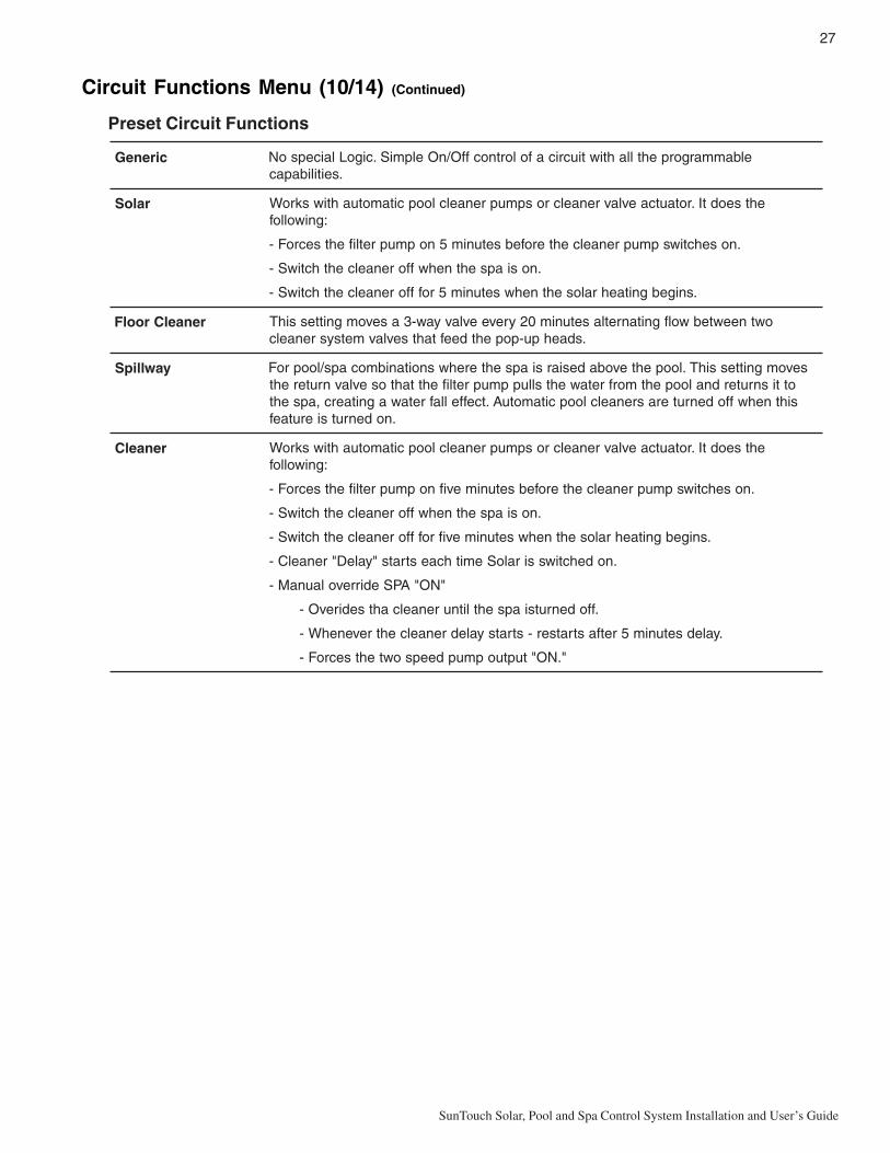
27
SunTouch Solar, Pool and Spa Control System Installation and User’s Guide
cireneG elbammargorpehtllahtiwtiucricafolortnocffO/nOelpmiS.cigoLlaicepsoN.seitilibapac
raloS ehtseodtI.rotautcaevlavrenaelcrospmuprenaelcloopcitamotuahtiwskroW:gniwollof
.nosehctiwspmuprenaelcehterofebsetunim5nopmupretlifehtsecroF-
.nosiapsehtnehwfforenaelcehthctiwS-
.snigebgnitaehralosehtnehwsetunim5roffforenaelcehthctiwS-
renaelCroolF owtneewtebwolfgnitanretlasetunim02yreveevlavyaw-3asevomgnittessihT.sdaehpu-popehtdeeftahtsevlavmetsysrenaelc
yawllipS sevomgnittessihT.loopehtevobadesiarsiapsehterehwsnoitanibmocaps/looproFottisnruterdnaloopehtmorfretawehtslluppmupretlifehttahtosevlavnruterehtsihtnehwffodenruterasrenaelcloopcitamotuA.tceffellafretawagnitaerc,apseht
.nodenrutsierutaef
renaelC ehtseodtI.rotautcaevlavrenaelcrospmuprenaelcloopcitamotuahtiwskroW:gniwollof
.nosehctiwspmuprenaelcehterofebsetunimevifnopmupretlifehtsecroF-
.nosiapsehtnehwfforenaelcehthctiwS-
.snigebgnitaehralosehtnehwsetunimevifroffforenaelcehthctiwS-
.nodehctiwssiraloSemithcaestrats"yaleD"renaelC-
"NO"APSedirrevolaunaM-
.ffodenrutsiapsehtlitnurenaelcahtsedirevO-
.yaledsetunim5retfastratser-stratsyaledrenaelcehtrevenehW-
".NO"tuptuopmupdeepsowtehtsecroF-
Circuit Functions Menu (10/14) (Continued)
Preset Circuit Functions

28
SunTouch Solar, Pool and Spa Control System Installation and User’s Guide
Settings Menu (11/14): QuickTouch® (QT4) Wireless Remote
The QuickTouch QT4 wireless remote controller provides switching of up to four circuits. For example, youcan use the QT4 wireless remote to activate the spa circulation, and for operating three auxiliary pieces ofequipment (such as heat enabled, lights, jet pump, heat boost, air blower, waterfall, etc.).
Each of the four functions on the QT4 wireless controller has an on and an off button. To switch a circuit onor off, press and hold the appropriate button for at least a full second.
The QT4 buttons can be assigned to any available circuit. However, the QT4 has the following preset circuitsassigned to the four buttons:
• The SPA button activates the spa circuit (same as the Up button on the SunTouch control panel.)• A button activates the AUX 1 circuit.• B button activates the AUX 2 circuit.• C button activates the AUX 3 circuit (see page 26 for AUX 3 assignment information).
Assign QT4 buttons
To assign circuits to the QuickTouch wireless controller buttons:
Menu button: Select the QuickTouch 11/14 menu.Right button: Assign the QuickTouch SPA button to a circuit.Up/Down buttons: Choose a circuit to assign to the SPA button. The circuitselections are: None, Spa, Pool, AUX 1, AUX 2, AUX 3, FEATURE 1 - 4, HEATBOOST, HEAT ENABLED. Selecting “None” does not assign a circuit.
Note: The “Heat Boost” feature will switch on the heater for seven minutes toincrease the spa water temperature. Each time the spa Heat Boost button ispressed, the temperature will increase about 1° F. The temperature will not gobeyond the 104° F (40° C) limit.
Right button: Assign button A to a circuit 1. Use the Up/Down buttons to select acircuit for button A. Repeat the process for Buttons B (AUX 2 circuit 2) and C (AUXcircuit 3).
Left button: Press the Left button to return to the main status screen.
QuickTouch2 - [POOL ]
QuickTouch3 - [AUX1 ]
Main Menu 11/14 QuickTouch
QuickTouch1 - [HEAT BOOST]
QuickTouchSPA - [SPA ]
Pump Menu (12/14)From the Pump menu you can setup SunTouch to operate a single-speed or two speed pump, or assign up toeight speeds and circuits for the IntelliFlo VS and IntelliFlo VF pump. SunTouch can be setup to operate eitherone IntelliFlo VS or one IntelliFlo VF pump. The SunTouch system communicates with the IntelliFlo VS andthe IntelliFlo VF pump via a two-wire RS-485 cable. For information about connecting the RS-485communication cable from SunTouch Power Center to the IntelliFlo pump, refer to the IntelliFlo VS Installationand User’s Guide (P/N 357269).
SINGLE SPEED FILTER PUMP
For a single-speed pump there are no assigned pump circuits. The pool filter pump schedule programdetermines when the pump is switched on and off. If the heat source is enabled in the “Heat” menu (see page14), when the pool or spa circuit is activated the selected heat source is also enabled. The default time beforethe filter pump will switch off is 12 hours. If the pool/spa circuit is switched off and the heater is operating,only the heater will turn off, then the filter pump will automatically switch off after 10 minutes to allow theheater to cool down. Pentair Water Pool and Spa® heaters do not require a cool down time. To override the“heater cool-down,” press the Filter Pump button again to switch off the pump.

29
SunTouch Solar, Pool and Spa Control System Installation and User’s Guide
To select a single-speed pump.
Menu button > Right button: Select the Pumps 9/14 menu.Right button: Press the button to select the pump settings.Up/Down buttons: Select Single Speed. A single-speed pump has no assignedcircuit. The pool filter schedule determines when the pump is switched on and off. Formore information, see Schedules Menu on page 17.Right button: Press this button to exit to the main menu items.
Left button: Press the Left button to return to the main status screen.
TWO SPEED FILTER PUMP
Note: There must be a two-speed relay installed in the SunTouch enclosure in order for the “Two-Speed” pump menu feature to operate. The two-speed relay circuit can assigned to AUX 1, AUX 2, AUX3 or FEATURE 1 - 4. This allows the pump to operate at low speed when required.
Assigned circuits will automatically switch a two-speed filter pump to high speed when these circuits areswitched on setup in the Schedules menu. If a two-speed pump is assigned to solar, a cleaner or a pump, whenactivated the pump will automatically run for five minutes in high speed then switch to low speed. Forexample, when on, the filter pump will switch to high speed whenever the JETS or CLEANER is on.
Menu button > Right arrow button: Select the Pumps 12/14 menu.Right button: Press this button to select the Pump Type.Up/Down buttons: Select TWO SPEED.Right button: Select Pump Circuits. You can assign up to four (4) 2-speed pumpcircuits and eight (8) IntelliFlo pump circuits.Up/Down buttons: Select up pump circuits. The pump circuit selections are: NONE,SPA, POOL, AUX 1, AUX 2, AUX 3, FEATURE 1 - 4, SOLAR, HEATER,FREEZE, POOL/SPA, and SOLAR/HT (solar/heater). Note: Selecting “Pool/Spa”or “Solar/HT” combines several circuits into the same pump speed for pool andspa or for solar and heater combination systems. Normally this would requireprogramming two separate pump speeds for each function. Using one of theseselections free-up one of the four pump speed for other uses.Right button: Select the second circuit settings for the pump. Use the Up/Downbuttons to select the circuit. If necessary, repeat this process to assign the third andfourth circuit for the pump.
Left button: Press the Left button to return to the main status screen.
Pump Type[SINGLE SPEED]
Main Menu 12/14 Pumps
Pump Type[TWO SPEED ]
Main Menu 12/14 Pumps
Pump Circuits1 - [POOL ]
Pump Circuits2 - [SPA ]
Pump Circuits3 - [HEATER ]
Pump Circuits4 - [FREEZE ]

30
SunTouch Solar, Pool and Spa Control System Installation and User’s Guide
Pump Menu (12/14) (Continued)
IntelliFlo® VS pumpFrom the IntelliFlo VS menu you can assign an auxiliary circuits to control four different pump speeds. Thepump speed can be adjusted from 400 to 3450 RPM in increments of 10 RPM. For more information about theIntelliFlo VS, refer to the IntelliFlo VS Installation and User’s Guide (P/N 357269).
To assign up eight (8) pump speeds and circuits for the IntelliFlo VS pump:
Menu button: Select the Pumps 12/14 menu.Right button: Press the button to view the type of pump to select.Up/Down buttons: Select IntelliFlo VS. Press Right button again to select.Press Up/Down buttons to view the pump parameters menus: SPEEDS,PRIMING or STATUS. Press Right button to select. Press the Right buttonagain to ASSIGN SPEEDS (RPM) setting. Press Up/Down buttons set the pumpspeed. Pump speeds can be set from 400 to 3450 RPM in increments of 10 RPM.The default speed for each circuit is the same as the four speed buttons on theIntelliFlo VS control panel. The preset speed which corresponds to each of the fourbuttons on the pump are: 1 button 750 RPM, 2 button 1500 RPM, 3 button 2350RPM, and 4 button 3110 RPM.Press Right button to ASSIGN CIRCUIT for the pump. Press Up/Down buttonsto view the circuits for the first of eight pump circuits: [NONE, SPA, POOL, AUX 1,AUX 2, AUX 3, FEATURE 1 - 4, SOLAR, HEATER, FREEZE, POOL/SPA, andSOLAR/HT (solar/heater)]. Press Right button to select the circuit. Note:Selecting “Pool/Spa” or “Solar/HT” combines several circuits into the samepump speed for pool and spa or for solar and heater combination systems.Normally this would require programming two separate pump speeds for eachfunction. Using one of these selections, free-up one of the four pump speed forother uses.Right button: Press this button to continue to assign pump SPEEDS andCIRCUITS. You can assign up to eight (8) pump speeds and circuits.When finished assigning speeds and circuits, press the Right button until SPEEDS isdisplayed, then press the Up/Down buttons and select PRIMING. Press Rightbutton to select Priming Params Time. Press the Up/Down buttons to set thepriming time (0 to 10 minutes). When finished, Press Right button to select PrimingParams Speed. Press the Up/Down buttons to set the priming speed (4000 - 3450RPM). To select STATUS, press the Right button three (3) time, then press theUp/Down button to select STATUS. Press the Right button to view the currentRPMs and operating Watts. Press the button again to view the current pumpcommunication status.Left button: Press the Left button to return to the main status screen.
Freeze ProtectionFreeze protection protects the pool, plumbing, and equipment against freeze damage. If the outside airtemperature sensor falls below 36° F (2° C), freeze protection is activated and the pool/spa filter pump relay isswitched on to circulate the pool water. To enable freeze protection for a circuit, see page 26. In order to usethe SunTouch freeze protection function, an optional sensor is required to monitor the air temperature. Toenable freeze protection and display the outside air temperature on the main screen, the “AIR SENSOR” mustbe enabled (see Advanced Menu 8/14 on page 24). Freeze protection is enabled whenever the outsidetemperature is 36º F or lower. When freezing conditions are detected by the air sensor, SunTouch will switchthe filter pump on and circulate pool water continuously through the pool and spa. For SunTouch “solar only”systems, the optional air sensor and an additional time clock connected to the filter pump is required for freezeprotection. Note: If multiple AUX circuits are set to ON, when freeze is active, the circuit will run thepump at the highest assigned speed of the active circuit.
Assign Speeds1 - RPM: 3450
Main Menu 12/14 Pumps
Pumps ParametersMenu: SPEEDS
Priming ParamsTime: 5
Assign Circuits1 - [ SPA ]
Status: NORMAL
RPM: 1500 75 W
Pump Type[INTELLIFLO VS ]
Pumps ParametersMenu: PRIMING
Priming ParamsSpeed: 1000
Pumps ParametersMenu: STATUS

31
SunTouch Solar, Pool and Spa Control System Installation and User’s Guide
Pump Menu (12/14) (Continued)
IntelliFlo® VF pump
From the IntelliFlo VF menu you can assign circuits to control the pump flow rate (GPM), priming, also filter,backwashing, vacuum functions and view the current pump status. For more information about the IntelliFloVS, refer to the IntelliFlo VF Installation and User’s Guide (P/N 350075).
To assign up eight (8) pump speeds and circuits for the IntelliFlo VS pump:
Menu button: Select the Pumps 12/14 menu.Right button: Press the button to view the type of pump to select.Up/Down buttons: Select IntelliFlo VF them press Right button again to select.Press Up/Down buttons to view the Pump Parameters menus: FLOWS,FILTER, PRIMING, BAKWASH, VACUUM, STATUS or FILTERCIRCUITS. Press Right button to select one of the parameters.Press the Right button again to ASSIGN FLOWS (GPM) setting.Press Up/Down buttons set the pump flow rate (15 - 130 GPM).Press Right button to ASSIGN CIRCUIT for the pump. Press Up/Down buttonsto view the circuits for the first of eight (8) pump circuits: [NONE, SPA, POOL,AUX 1, AUX 2, AUX 3, FEATURE 1-4, SOLAR, HEATER, FREEZE, POOL/SPA, and SOLAR/HT (solar/heater)].
Press Right button to select the circuit. Note: Selecting “Pool/Spa” or “Solar/HT” combines several circuits into the same pump speed for pool and spa or forsolar and heater combination systems. Normally this would require programmingtwo separate pump speeds for each function. Using one of these selections, free-up one of the four pump speed for other uses.
Press Right button to continue to assign pump FLOWS and CIRCUITS. You canassign up to eight (8) pump speeds and circuits.
When finished assigning pump flow rate and circuits, press the Right button untilFLOWS is displayed, then press the Up/Down buttons and select FILTER.
Press Right button to select Filter Params Time. Press the Up/Down buttons toset the Filter Size (1000 to 255000 gallons).
Press Right button to select Filter Params Manual Filter. Press the Up/Downbuttons to set the Filter Size (15 - 130).
When finished, Press Right button to select Filter Params Turns. Press the Up/Down buttons to set the number of pool cycle turns (1-4).When finished assigning filter parameters, press the Right button until FLOWS isdisplayed, then press the Up/Down buttons and select FILTER.
Press Right button to select Filter Params Time. Press the Up/Down buttons toset the Filter Size (1000 to 255000 gallons).
Press Right button to select Filter Params Manual Filter. Press the Up/Downbuttons to set the Filter Size (15 - 130).
Assign Flows1 - GPM: 3450
Main Menu 12/14 Pumps
Pumps ParametersMenu: FLOWS
Assign Circuits1 - [ SPA ]
Pump Type[INTELLIFLO VF ]
Filter ParamsSize: 25000
Pumps ParametersMenu: FILTER
Filter ParamsTurns: 2
Filter ParamsMan Filt: 30

32
SunTouch Solar, Pool and Spa Control System Installation and User’s Guide
Pump Menu (12/14) (Continued)
IntelliFlo® VF pump
When finished, Press Right button three times until FILTER is displayed.Press the Up/Down buttons to select PRIMING.Press the Right button to select Priming Params: Max Flow.Press the Up/Down buttons to select the maximum flow GPM rate (15-130).Press the Right button to select the Max Time, press the Up/Down buttons toselect the maximum time from 1 to 15 minutes.Press the Right button to select the Sys Time, press the Up/Down buttons toselect the maximum time from 1 to 15 minutes.
When finished assigning filter parameters, press the Right button until PRIMING isdisplayed, then press the Up/Down buttons to select BACKWASH.Press Right button to select Backwash Params Clean Filt:Press the Up/Down buttons to set the filter clean time (1-50 minutes).Press Right button to select Flow GPM. Press the Up/Down buttons to set theflow rate (15-130 GPM).Press Right button to select Duration. Press the Up/Down buttons to set theduration (1-60 minutes).Press Right button to select Rinse Time. Press the Up/Down buttons to set therinse time (1-60 minutes).
When finished assigning filter parameters, press the Right button untilBACKWASH is displayed, then press the Up/Down buttons to select VACUUM.Press Right button to select Vacuum Params Flow (gpm): Press the Up/Downbuttons to set the gpm flow rate (15-130 GPM).Press Right button to select Flow GPM. Press the Up/Down buttons to set theflow rate (15-130 GPM).Press Right button to select Time (min). Press the Up/Down buttons to set thevacuum time (1-600 minutes).Press Right button to select Rinse Time. Press the Up/Down buttons to set therinse time (1-60 minutes).
When finished assigning vacuum parameters, press the Right button untilVACUUM is displayed, then press the Up/Down buttons to select STATUS.Press Right button to view the current RPM, WATTS and GPM status.Press the Right button again to view the Filter and pump operation status.
When finished assigning vacuum parameters, press the Right button until STATUSis displayed, then press the Up/Down buttons to select FILT. CIRC.Press Right button to view the filter circuits. Press the Up/Down buttons to selectthe circuit: (NONE, SPA, POOL, AUX 1, AUX 2, AUX 3).
Left button: Press the Left button to return to the main status screen.
Backwash ParamsClean Filt: 10
Pumps ParametersMenu: BACKWASH
Priming ParamsFlow GPM: 60
Priming ParamsDuration: 5
Priming ParamsRinse Time: 5
Vacuum ParamsFlow (gpm): 65
Pumps ParametersMenu: VACUUM
Vacuum ParamsTime (min): 30
Filter: 0Status: NORMAL
RPM: 1500 75 WGPM: 50
Pumps ParametersMenu: STATUS
Filter Circuit[ POOL ]
Pumps ParametersMenu: FILT. CIRC
Priming ParamsMax Flow: 55
Pumps ParametersMenu: PRIMING
Priming ParamsMax Time: 5
Priming ParamsSys Time: 1

33
SunTouch Solar, Pool and Spa Control System Installation and User’s Guide
IntelliChlor Menu (13/14)The IntelliChlor menu features allow you to view the current salt level (ppm) status, enable or disable theIntelliChlor cell, control the amount of chlorine production and to super chlorinate your pool/spa. While innormal operating mode (Pool, Spa mode or Spa Fill (Spillway), SunTouch will control the chlorinator outputlevel. When IntelliChlor is connected to the SunTouch COM port on the motherboard, chlorination levels canonly be changed from the SunTouch control panel. The IntelliChlor control panel will be disabled. The amountof chlorine introduced into the pool is determined by the amount of salt in the water, the water temperature andthe amount of time the pool operates in “Pool/Spa” mode. The IntelliChlor menu features are active when theIntelliChlor electronic salt chlorine generator is connected to the COM port on the SunTouch motherboard.Note: While in “Freeze Protection” mode, IntelliChlor will not operate during the time that the filterpump is operating. For more information, refer to the IntelliChlor Electronic Chlorine Generator User’sGuide (P/N 520589).
IntelliChlor
To setup IntelliChlor electronic chlorine generator:
Menu button: Select the IntelliChlor menu.Right button: Enable or Disable IntelliChlor setting.Up/Down buttons: Select Yes to enable or No to disable IntelliChlor.Right button: Move to set the chlorine level for the pool.Up/Down buttons: Set the percentage amount of chlorine to produce in the pool. Setthe chlorination output level for the pool/spa water from 0 to 100%. SunTouch willdetermine the chlorinator output level when the system is operating in “Spa” or “Pool”mode. The amount of chlorine introduced into the pool/sap is determined by theamount of salt in the water, the water temperature and the amount of time the pool/spa operates in these modes mode. Use the Up button to increase the percentagelevel, and the Down button to decrease the percentage level.Right button: Move to set the chlorine level for the spa.Up/Down buttons: Set the percentage amount of chlorine to produce in the spa. Setthe percent level from 0% to 100% (Super Chlorination). Use the Up button toincrease the percentage level, and the Down button to decrease the percentage level.Right button: Move to the Super Chlorination settings (see below). If you do notwant to Super Chlorinate the pool/spa, press the Right button to skip these settingsuntil the salt level/status screen displays.
IntelliChlor status and error messages:
Up/Down buttons: The current pool/spa salt level (ppm) is displayed on the screen.If an IntelliChlor error is detected, an error message will be is displayed on thescreen. To view the IntelliChlor status and error messages, see “IntelliChlor Statusand Error Messages” on page 32. Press the Right button to return to the main menuitems.
Super Chlorination:
Up/Down buttons: Select Yes to enable Super Chlorination or No to disable SuperChlorination.Right button: Move to the Super Chlorination “Run Hours” setting.Up/Down buttons: Set the number of hours to run Super Chlorination. 24 hours isthe default setting. The run hours can be set from 0 to 72 hours. Use the Up button toincrease the run hours, and the Down button to decrease the run hours.The display shows the current salt level in the water.Left button: Press the Left button to return to the main status screen.
IntelliChlorEnable: YES
IntelliChlorPool %: 50
IntelliChlorSpa %: 0
Main Menu 13/14 IntelliChlor
IntelliChlorSuper Chlor: YES
IntelliChlorRun Hours: 12
Salt: 2900 ppm[OK - NO ERRORS]
Salt: 3200 ppm[SUPR CHLRINATE]

34
SunTouch Solar, Pool and Spa Control System Installation and User’s Guide
IntelliChlor Menu (13/14): Status and Error Messages
If an error alert, or warning is detected by IntelliChlor, the error message will be displayed on the SunTouchcontrol panel screen. All status and error messages can be viewed from the IntelliChlor menu. Fortroubleshooting information, refer to the IntelliChlor Electronic Chlorine Generator User’s Guide (P/N 520589).
To view the IntelliChlor status and error messages:
Menu button: Select the IntelliChlor menu.Right button: Press the button until the Salt status screen is displayed.Displays the current IntelliChlor chlorination system status.Left/Right button: Press the Left or Right button to return to the main statusscreen.IntelliChlor status and error messages:
SALT LEVEL: Displays the current salt level. Values from 0 to 12750 ppm in 50 ppmincrements.IntelliChlor Status and Error messages:
SUPER CHLORINATE: IntelliChlor is in Super Chlorination mode. For informationCOM LINK ERROR: Check cable from IntelliChlor to SunTouch motherboard.Check FLOW/PCB: Check IntelliChlor electrolytic cell controller. Refer to IntelliChlorUser’s Guide troubleshooting information.LOW SALT: Add salt to pool water. The water salt level is between 2500 ppm and2950 ppm. The IntelliChlor will continue to produce chlorine at a reduced level.VERY LOW SALT: Not enough salt in pool. The water salt level has fallen below 2500parts per million (ppm). IntelliChlor will not produce chlorine until additional salt isadded manually.HIGH CURRENT: Check IntelliChlor electrolytic cell controller. Refer to IntelliChlorUser’s Guide troubleshooting information.CLEAN CELL!!: Cell has calcium build up and requires cleaning. Refer to IntelliChlorUser’s Guide for cleaning instructions.LOW VOLTAGE: Check IntelliChlor electrolytic cell controller. Refer to IntelliChlorUser’s Guide troubleshooting information.OK - NO ERRORS: IntelliChlor is in normal operating mode.
About Super Chlorination: The Super Chlorination feature is used to introduce large amounts of chlorineinto the pool water if there has been heavy rain fall, many bathers in the pool, cloudy water conditions, etc.When Super Chlorination is enabled, the system will switch on the filter pump, set the pool/spa valves to thecorrect position, and set the IntelliChlor chlorine generator to maximum output. This process continues for 24hours. At the end of the Super Chlorination process, the system will return to normal operation. It is possible tomanually stop the Super Chlorination process and switch off the filter pump in the “Circuit On/Off” menu(see page 13). When the filter pump is switched on again, the Super Chlorine process will resume for theduration of time that is left.
Main Menu 13/14 IntelliChlor
Salt: 3200 ppm[OK - NO ERRORS]

35
SunTouch Solar, Pool and Spa Control System Installation and User’s Guide
Service Menu (14/14): Service, Timeout, Auto
The Service operation features allow manual control of the SunTouch system for pool service purposes. Theactive service operating mode (Service Mode or Timeout Mode is displayed on the main screen.
Service mode: This mode allows the auxiliary circuit buttons, filter pump, valves, heater and solar functions tobe operated manually. All control panel buttons, remote controllers, and menu scheduled programs are disabledwhile the system is in Service mode, except for switching off equipment manually for emergencies. If a poweroutage occurs while SunTouch is in Service mode, after power is restored the system will power up in Servicemode.Timeout mode: Allows manual control of the SunTouch system for three (3) hours. After three hours thesystem will automatically return to normal operation (Auto mode). Manual controls for Timeout mode aresame as Service mode. All control panel buttons, remote controllers, and menu scheduled programs aredisabled while the system is in manual mode, except for switching off equipment manually for emergencies. Ifa power outage occurs while SunTouch is in Timeout mode, after power is restored the system will power upin AUTO mode.Auto (automatic) mode: The SunTouch system is in normal operating mode.
To access the Service or Timeout menu settings:
Menu button: Select the Service (14/14) menu.Right button: Press the button to access the System operation menu.Up/Down buttons: Select SERVICE or TIMEOUT.Right button: To access the Service or Timeout settings and each of the selectionsshown below.Up/Down buttons: Select the setting.
The Service selections are:
F Pump: OFF, ON, HI SPDVLV A, B: POOL, DRAIN, FILL, SPAHeater: OFF, ONSolar: OFF, ONAUX 1, AUX, 2, AUX 3: OFF, ONVLV C: OFF, ON
Left/Right button: Press the Left or Right button to activate Service or Timeoutmode and return to the main status screen. The active service operating mode isdisplayed on the main screen while in shared equipment, single body, and solar onlyoperating modes.
To exit Service Mode or Timeout Mode:
Menu button: Select the Service (14/14) menu.Right button: Press the button to access the System operation menu.Up/Down buttons: Select AUTO.Left or Menu button: Press the Left or Menu button to return to the main statusscreen.
Main Menu 14/14 Service
System Operation[AUTO ]
Service Mode 6:27 AM
Main Menu 14/14 Service
System Operation[AUTO ]
System Operation[SERVICE ]
Service SettingsF Pump: OFF
Service SettingsVLV A, B: POOL
Service SettingsHeater: OFF
Service SettingsSolar: OFF
Service SettingsAUX 1: OFF
Service SettingsVLV C: OFF
System Operation[AUTO ]
System Operation[SERVICE ]

36
SunTouch Solar, Pool and Spa Control System Installation and User’s Guide
SunTouch Main Status Screen (Pool/Spa Mode - Single Body System)
Use the SunTouch display to view the daily operations of your spa or pool. Using the UP arrow button(HI-TEMP) to manually switch the filter pump on and off and activate the heater. LOW temperature controlcan also be assigned to the UP arrow button. The “HIGH” and “LOW” circuit can be programmed to run at aspecific time and heat setting. These circuits are assigned in the “Circuit Functions” menu (see page 26).Before using SunTouch to operate a single body system (pool only or spa only), familiarize yourself with thestatus screen and control buttons.
AIR: Displays the outside air temperature via the air sensor
located near the pool area. This screen toggles betweenthe “Pool” or “Spa” display (see below). To display the airtemperature setting, the air sensor must be enabled(see “Advanced” menu on page 24). Degree units aredisplayed in either Fahrenheit or Celsius. If the topdisplay line displays “SunTouch”, it indicates no spa orpool function is active and the air sensor is not enabled.
HIGH: When the Up arrow button is pressed or this circuit is scheduled
to operate, the “HIGH” filter pump circuit is switched onand current water temperature settings are displayedwith the heat source being used. “HIGH” and “LOW” aredisplayed alternatively if both circuits are active.
LOW: When the Down arrow button is pressed or this circuit is
scheduled to operate, the “LOW” filter pump circuit isswitched on and current water temperature settings aredisplayed with the type heat source being used. “HIGH”and “LOW” are displayed alternatively if both circuits areactive.
®
HIGH 75°F / 85°F11:51AM HEATER
HI-TEMP/LO-TEMP button: Turnheater and filter pump on or off.To activate the heater when thisbutton is pressed, first select heatsource in the “Heat 2/14” menu(page 14). To manually switch onor off the heater, use “ManualHeat” in the “Heat 2/14” menu.The heat temperature settingsare displayed on the mainscreen. This button can also beassigned for LOW temperaturecontrol (see page 37).
AUX 1: When this button ispressed, the circuit relay con-nected to AUX 1 is switched onand the number 1 is displayed onthe lower right-side of the screen.AUX 1 can also be switched onand off manually from the “CircuitOn/Off” menu (see page 13).Auxiliary functions are assign inthe “Circ. Function” menu seepage 26). AUX 1 can be assign tooperate accessory equipmentsuch as pool and spa lights.
HEATER: Displays the heat source (Heater, Solar Prf., Solar)as specified in the “Heat” menu settings (see page 14). If heat isenabled, when the pool filter pump is switch on, the heat sourceis displayed.75° F / 85° F: Displays the actual spa or pool water temperature(75° F) and the set point temperature (85° F) as set in the“Heater” menu (see page 14). To adjust set temperature settinguse the (-) TEMP and (+) TEMP buttons.
Time: Displays the SunTouch system time as set in the “Clock”menu setting (see page 19).
AUX 1 2 3: Displays AUX 1, 2, 3 (lower line) when these auxiliary relay circuits are
switched on. Press the AUX 1 (1) button to manually switchauxiliary 1 on or off. AUX 2, and AUX 3 can be switch on and offmanually from the “Circuit On/Off” menu (page 13). Auxiliaryfunctions are assign in the “Circ. Function” menu (page 26).
AUX D: “D” indicates the selected circuit (AUX 1,2,3) is in “delay” mode. For
example, if AUX 2 is assigned to a cleaner, when the auxiliarycircuit 2 is switched on via the “Circuit On/Off” menu setting, thiswill force the filter pump on for five (5) minutes before thecleaner pump switches on. See “Circuit Functions Menu” (page26) for more information.
HIGH 75°F / 85°F11:51AM HEATER
LOW 75°F / 85°F11:51AM HEATER
AIR 74°F 11: 51AM AUX 1
FRZ: Indicates the air sensor is connected and enabled, and“Freeze Protection” is active (see page 26).
AIR 36°F FRZ 11: 51AM AUX 1
AIR 77°F 11: 51AM AUX D
Lower current set pointtemperature setting
Raise current set pointtemperature setting
AIR 77°F 11: 51AM AUX 123

37
SunTouch Solar, Pool and Spa Control System Installation and User’s Guide
High/Low Temperature Circuit Control (Single Body System)
HI-TEMP / LO-TEMP Circuit Controls
For SunTouch single body systems (pool only or spa only), theHI-TEMP (UP arrow) button is used to switch the heater(regardless of the Heat menu setting) and filter pump on andoff. Typically this circuit is used with the “Manual Heat”feature (see below) for on-demand spa water heat. The heattemperature settings are displayed on the main screen. Theheater is active when the set temperature is higher than thewater temperature. The heater will switch off when the watertemperature rises above the set temperature. The heattemperature settings are displayed on the main screen.
The LO-TEMP on and off control is made from the Heat menu setting. For SunTouch single body systems(pool only or spa only, see page 35), the LO-TEMP menu setting is used to switch on and off the heat sourceand filter pump. A heat selection must be selected in the Heat menu before the heater is activated. The“Manual Heat” setting does not function with the LO-TEMP circuit. The heater is active when the settemperature is higher than the water temperature. The heater will switch off when the water temperaturerises above the set temperature.
SunTouch Single Body system notes
• The SPILLWAY circuit selection in the Circ.Functions menu has no function.
• When using a 2-Speed relay, AUX 3 is assigned to the “HIGH” circuit.
Setting up SunTouch to operate as a Single Body system
To setup SunTouch as a “Single Body” of water system (pool only or spa only):
Menu button: Select the Advanced menu (8/14).Right button: Select the System Type setting.Up/Down button: Select Single Body to configure SunTouch as a single body ofwater system.Left button: Press the Left button to return to the main status screen.
System TypeSingle Body
Main Menu 8/14 Advanced
®
HIGH 75°F / 85°F 11:51AM HEATER

38
SunTouch Solar, Pool and Spa Control System Installation and User’s Guide
Note: (*) See page 6 for "SOLAR ONLY" menu.
Filter Pump: [Circuit On/Off - LOW: On/Off] - Default Off (page 13) AUX 1, AUX 2, AUX 3 [On/Off], FT 1, FT 2, FT 3, FT 4 [On/Off]
Circuit On/Off 1/14
LOW Temp [40˚ F - 104˚ F] or [4˚ C - 40˚ C] (page 14)LOW Heat (Source) [Off, Heater] [Solar, Solar Prf - displays if "Solar" is enabled in "Solar" menu] (page 19)HIGH Temp [40˚ F - 106˚ F] or [4˚ C - 41˚ C]HIGH Heat (Source) [Off, Heater] [Solar, Solar Prf - displays if "Solar" is enabled in "Solar" menu] (page 19)Manual Heat: [ON/OFF] - Default On (page 15)
Heat 2/14
Press Right button to cancel delays - [Delayed Cancelled] (page 16)Delay Cancel 3/14
Schedules: [LOW, HIGH, AUX 1 - 3, FT 1 - 4] (page 17) Program: 4/4 [Add, Edit, Skip, Delete]Schedule: Start/Stop [08:00A - 05:00P] 12:00 AM - 11:59 PM - 12 Hours
Schedules 4/14
Time Set: 06:00 AM [Hour/Minutes - AM/PM] (page 19)Clock 5/14
Solar Status: Enabled [NO / YES] - Default No (page 19 - 20) Heat Start Temp Diff: Temp Diff [6 %] - [6-9%] - Heat Stop Temp Diff: Temp Diff [3 %] - [3-5%] Heat Pump: [Yes/No] - Default No - Cooling Enabled: [Yes/No] - Cool Start Temp Diff: Temp Diff [6 %] - Cool Stop Temp Diff: Temp Diff [3 %]
Solar 6/14
Valves Circuit: [HIGH, LOW, AUX1 - 3, FEATURES 1 - 4, SOLAR, HEATER, FREEZE, NONE] (page 21) [SOLAR displays if "Solar" is enabled, see page 19]
Valves 7/14
Low Circuit: Freeze [Off/On] - Default Off (page 26) - High Circuit: Freeze [Off/On] AUX 1 - 3 Circuit: [Generic, Cleaner, Spillway, Floor Cleaner, Heater, Solar] - Freeze: [Off/On
Circ. Functions 10/14
IntelliChlor: Enable [No / Yes] (page 32)Pool %: (0% - 100%) - 50 (Default) - Spa %: (0% - 100%) - 8 (Default)Super Chlr: (No/Yes) - 23 (Default) - Run Hours: (0 -72) - 0 (Default)IntelliChlor - Salt Level: Displays current salt level (xxxx) ppm - Status: OK - NO ERRORS (SUPER CHLORINATE, COM LINK ERROR, CHECK FLOW / PCB, LOW SALT, VERY LOW SALT, HIGH CURRENT, CLEAN CELL!!, LOW VOLTAGE)
IntelliChlor 13/14
Firmware Rev: (Displays the system firmware revision level) (page 25)Solar Temp: [Fahrenheit/Celcius - Status display only] - (Displays if Solar is enabled in Heat menu)Self Test: [Yes/No]
Diagnostics 9/14
SINGLE SPEED - TWO SPEED - INTELLIFLO VS - INTELLIFLO VF (page 29 - 32) TWO SPEED - Pump Circuits 1-4: [Spa, Pool, AUX1- 3, FEATURE 1 - 4, Solar Heater, Pool Heat, Spa Heat, Freeze, Pool/Spa, Solar/HT, None]INTELLIFLO VS - Pump Params Menu: SPEEDS - Assign 1-8 Speeds: RPM 1000 default [400 - 3450 RPM] Assign 1-8 Circuits: [Spa, Pool, AUX1- 3, FEATURE 1 - 4, Solar Heater, Pool Heat, Spa Heat, Freeze, Pool/Spa, Solar/HT, None] 1-8 - RPM 1000 default [400 - 3450] - PRIMING - Priming Params Time: 1 [1-10] - Speed: 1000 [400 - 3450 RPM] - STATUS - RPM: 0 - 3450 - 0 Watts - Status Normal INTELLIFLO VF - Pump Params Menu: FLOWS - Assign Speeds 1-8 pumps - GPM 30 default [15 - 130 GPM] - Assign Circuits 1-8 circuits [None, Spa, Pool, AUX 1- 3, FEATURE 1- 4, Solar, Heater, Pool Heat, Spa Heat, Freeze, Pool/Spa, Solar/HT] FILTER - Filter Params Menu: SIZE - 15000 default [1000 - 255000] - TURNS - 1 default [1 - 4] - Man Filt - 30 default [15 - 130 GPM] BACKWASH - Filter Params Menu: Max Flow - 55 default [15 - 130 GPM] - Max Time - 5 default [1 - 5 mins] -- Duration - 1 default [1 - 5 mins] - Rinse Time - 1 default [1 - 60 mins] - VACUUM - Vacuum Params Menu: Flow (GPM) - 50 default [15 - 130] - Time (min) - 1 default [1 - 599] -- Sys Time - 1 default [1 - 60 mins] - STATUS - RPM: 0 - 3450 - 0 Watts - GPM: 0 Filter: 0 - Status Normal FILT. CIRC - [None, Spa, Pool, AUX 1-3]
Pumps 12/14
QuickTouch 11/14 QuickTouch - Assign 1 - 4 circuits (page 28)Button 1, 2, 3, 4 [High, Low, AUX 1- 3, FEATURE 1 - 4, Heat Boost, Heat Enabled, None]
Advanced 8/14 Heater Delay: [No/Yes] (page 22)Temp Units: [FAHRENHEIT / CELSIUS]Calibrate Water: Temp 10˚ F - Calibrate Air: Temp 90˚ F - Calibrate Solar: Temp 100˚ F - Air Sensor: [On/Off] - (Default On) - See page 24 - System Mode: [Pool/Spa, Solar Only*]System Type: [Shared Equipment, Single Body] - Circuit Timeout: 12 hours [1 - 23 Hours]Reset Factory: [Erase ALL? (No/Yes]
Service 14/14 System Operation: [AUTO, SERVICE, TIMEOUT] (page 35) - Service Settings: F Pump: On/Off, HI SPD - VLV A, B: Pool, Drain, Fill, Spa - Heater: Off/On, Solar: Off/On, AUX 1 - 3, FT 1 - 4, VLC: (On/Off) - AUTO - [Solar On/Off - only]
Pool/Spa Mode (Single Body of Water) MenusFor menu descriptions, see “The Pool/Spa Mode Menus” on page 13.

39
SunTouch Solar, Pool and Spa Control System Installation and User’s Guide
Section 2Installation and Setup
SunTouch System Installation Steps SummaryThe recommended SunTouch system installation steps are:
Review, prepare and install SunTouch Power Center (pages 46): Review high voltage connections.Prepare and install the SunTouch Power Center at the equipment pad. AC power for SunTouch should beprovided from the main-panel circuit breaker located at the house.
Remove SunTouch Power Center knockouts, install conduit and low voltage wire to the Power Center(page 50).
Install Auxiliary Relays and Valve Actuators (page 55-57): Install auxiliary relays, valve actuators, andconnect actuator cables to the SunTouch motherboard (VLV A, VLV B, or VLV C).
Install Temperature Sensors and Heat Thermostat (page 58): Install water and air sensors. Connectsensor cable plugs to the SunTouch motherboard.
Optional Equipment - Connecting IntelliChlor and IntelliFlo VS and VF pumps (page 72-73): Connectthe IntelliChlor and IntelliFlo VS or IntelliFlo VF communication cable to the SunTouch motherboard toconnector COM PORT.
SunTouch System Start-up (page 60): Perform a system start-up procedure.
Setting up SunTouch after equipment installation using main menu (page 63): Configure the SunTouchcontrol panel via the main menu for installed equipment.
Required Tools
• 3/16 in. diameter drill (for mounting the SunTouch Power Center)
• 5/16 in. diameter drill (for mounting water temperature sensor)
1
2
3
4
5
6
7

40
SunTouch Solar, Pool and Spa Control System Installation and User’s Guide
SunTouch Solar Package ContentsSunTouch Solar (P/N 520819)
• SunTouch Power Center - QTY 1• Valve actuator assembly (P/N 263045) - QTY 1• Solar valve (P/N 263047) - QTY 1• Temperature sensors (20 ft. water, solar 40 inches) - QTY 2
SunTouch Solar with non-solar 3-way valve (P/N 520856)• SunTouch Power Center - QTY 1• Actuator (P/N 263045) - QTY 1• Valve, three-way (P/N 263026) - QTY 1• Temperature sensors - (20 ft. water, solar 40 inches) - QTY 2
SunTouch Booster Pump Version (P/N 520857)• SunTouch Power Center - QTY 1• Relay (P/N 520106) - QTY 1• Temperature sensors (20 ft. water, solar 40 inches) - QTY 2
SunTouch Control System ContentsSunTouch Single Body (P/N 520859)• SunTouch Power Center - QTY 1• Relay (P/N 520106) - QTY 3• Temperature sensors (20 ft. water, air 40 inches) - QTY 2
SunTouch Pool/Spa - Shared Equipment (P/N 520820)• SunTouch Power Center - QTY 1• Actuator (P/N 263045) - QTY 2• Relay (P/N 520106) - QTY 3• Temperature sensors (20 ft. water, air 40 inches) - QTY 2
Accessories• QuickTouch remote controller kit (P/N 520148)• Relay (P/N 520106)• Temperature sensor (P/N 520272)• Two-Speed pump relay (P/N 520198)• Emergency Shut-Off Switch with audible alarm (P/N ES03)
Replacement Parts
• SunTouch Power Center door (P/N 520814Z)• SunTouch Power Center door Latch (P/N LXLATCH)• Temperature sensor kit (20 ft.) - (P/N 520272)• SunTouch circuit board (P/N 520645Z)• QuickTouch remote controller (P/N 520129)• QuickTouch antenna replacement (P/N 520241)• QuickTouch circuit board assembly (P/N 520419)• Standard transformer kit (P/N 520841Z)
Optional Equipment
• IntelliChlor Electronic Chlorine Generator Electrolytic Cell(model IC20 (P/N 520554) or IC40 (P/N 520555)
• IntelliFlo VS pump (P/N 011013)
SunTouch Power Center
CVA-24T Valve Actuator(P/N 263045)
PTV-2TS 3-Port Valve(P/N 263047)
10 k Ω Temperature Sensor(P/N 520272)

41
SunTouch Solar, Pool and Spa Control System Installation and User’s Guide
SunTouch System Overview
• PumpsFilter, Cleaner, Spa Jet -1.5 HP 120 VAC3 HP 277 VAC20 FLA/120 LRA,120 VAC17 FLA/102 LRA, 277 VAC
• Pool/Spa Lights1.5 KW 120 VAC Tungsten4.8 KW 240 VAC Tungsten20 AMP, 277 VAC Ballast
• Pool/Spa ValveSuction and return.24 VAC valve actuator,shared equipment only
• Valve actuatorsValve A (intake), Valve B(return), Valve C (Solar)
• Heat SourceGas, Electric and Solar
• Relays (3 maximuminstalled in powercenter)25 AMP, 277 VAC
Optional equipment
• IntelliChlor Salt ChlorineGenerator (SCG)
• IC20 P/N 520554/520556• IC40 P/N 520555/520556• Power Center
P/N 520556
• IntelliFlo VS (P/N 011013)IntelliFlo VF (P/N 011012)(see page 30)
Temperature Sensors(Water, Air and Solar)
SunTouch enclosure (with tworesettable circuit breakers(18 VAC and 24 VAC).
Electrical Ratings:Input:120/240 VAC, 60/50 Hz,820/410 mA maximum.Output:120 VAC, 20 FLA/120 LRA,1.5 HP.277 VAC, 17 FLA/120 LRA,3.0 HP.20 AMP Tungsten, 50/60 Hz.
QuickTouch (QT4)Wireless remote kit
(P/N 520148)(Optional)

42
SunTouch Solar, Pool and Spa Control System Installation and User’s Guide
SunTouch Power Center (Front View)
SunTouch Power Center (Front View)(14” H x 12” W x 4¾” D)
Control Panel LCD and buttons
1” Grommet for low voltagewires
(Air and watertemperature sensors,
motorized valves)
Spring latch
Enclosurefront door
Two ½" and one ¾"conduitknockout for high voltage wires
Low voltage push-buttoncircuit breakers
(18 VAC / 24 VAC)
Front panel handle
Retaining screw
Mountingbracket (x3)

43
SunTouch Solar, Pool and Spa Control System Installation and User’s Guide
Plumbing RequirementsIt is important that the pool and spa plumbing system be in accordance with local codes and the RecommendedHydraulic Schematics. Before starting, please review the diagrams and the following recommended guidelines:
The spa should be at or above the level of the pool.
If the spa is attached to the pool, provide a dam between the two bodies of water to allow the spa tooverflow into the pool. If the spa is not attached to the pool, an overflow, sufficient in size to carry a fullpump-flow, must be installed at the water level in the spa.
Plumb a three-port Intake Valve (VLV A) on the suction-side of the filter pump, so that the center portof the valve is connected to the pump inlet. Connect the spa suction to one side of the Intake Valve, andthe pool suction to the other side.
Plumb a three-port Return Valve (VLV B) on the return-side of the heater, so that the return water willenter the valve through the center port.
Connect the spa return to one side of Return Valve, and the pool return to the other side.
If required, install a spa makeup line (consisting of a manual gate or ball valve, for elevated spas install acheck valve) to bypass the pool return line. This will enable some of the chemically-balanced water fromthe pool to cycle through the spa. The manual valve will allow the amount of bypass to be adjusted.
For systems which incorporate a skimmer, it is possible to balance the amount of suction between theskimmer and main drain for maintenance purposes. This is easily accomplished by installing a manualthree-port mixing valve at the suction line. Plumb one port to the skimmer and the other to the main drain.
If a “non-booster pump” pressure-side pool cleaner is being used, plumb a manual three-port valvebetween the filter pump and filter, with the third port plumbed to the pool cleaner line, and install amotorized two-port Pool Cleaner Valve at this line. The motorized valve will automatically openwhenever the SunTouch activates the pool cleaner.
If a booster pump pool cleaner is being used, plumb the booster pump so that its suction-side is connectedto the pool return, after the heater, and as close to the ground as practical.
1
2
3
4
5
6
7

44
SunTouch Solar, Pool and Spa Control System Installation and User’s Guide
Plumb the solar feed and return lines between the filter and the heater. Install a three-port valve at thefeed line. Use a solar valve (P/N 263047)), to allow automatic draining of the panels.
A solar booster pump should be used when the distance to the panels exceed 200 ft., or the panels areelevated higher than 25 ft.
Glazed solar panels require a drain valve to allow draining of the panels. This prevents damage fromoverheating water. Install a drain valve at the solar feed line and connect to the pool fill line.
Equipment Location
All equipment, with the exception of the spa-side remote, must be located at least 10 ft. from the water’sedge.
INTELLICHLOR
SUNTOUCHPOWER CENTER
Recommended Hydraulic Schematic for Shared Equipment System
8
9
10

45
SunTouch Solar, Pool and Spa Control System Installation and User’s Guide
Solar Hydraulics SystemPlumb the SunTouch solar system in accordance with recommended hydraulics shown below.
• 2” diameter plumbing is advised to ensure maximum flow of water through the solar panels. A solarbooster pump should be added if panels are installed at a very high elevation.
• It is recommended that the solar panels are mounted in a way that gravity will allow drainingwhenever the filter pump is not on.
• For systems with glazed panels, damage can occur from overheating if the filter pump is still runningafter the solar has turned off. To enable glazed panels to automatically drain whenever the solar turnsoff (even if the filter pump is still running), a 1/2” motorized solar drain valve should be plumbed fromthe solar feed line, through a check valve, to a zero psi point (such as pool fill line or jet air intake).
Recommended Hydraulic Schematic for Single Body Equipment System
SunTouch Power Center

46
SunTouch Solar, Pool and Spa Control System Installation and User’s Guide
SunTouch Power Center High Voltage Connections
WARNING - BEFORE OPENING THE FRONT PANEL OF THE SUNTOUCH POWER CENTER TOACCESS THE HIGH VOLTAGE COMPARTMENT AND LOW VOLTAGE RACEWAY, SWITCH THE MAINPOWER OFF INTO THE HOME AT THE MAIN CIRCUIT BREAKER BOX, AND SWITCH OFF THE MAINPOWER TO THE SUNTOUCH POWER CENTER.
SunTouch Power Center Location
Before installing the SunTouch Power Center read the following guidelines:
• Switch OFF AC power at the main circuit breaker panel, located at the house before high and lowvoltage connection to the SunTouch Power Center.
• AC power for the SunTouch Power Center must be provided from the main circuit breaker panellocated at the house.
• All electrical equipment must be installed at least five (5) feet from pool and/or spa, and comply withall national, state, and local codes.
• Install the SunTouch Power Center no less than five (5) feet from pool or spa near to the pumps,heater, valves, and sensors. Mount the Power Center outside or inside a pool equipment house orother enclosure.
• Before choosing the final location for the SunTouch Power Center, consider the length of the wiresand valve wires that have to be connected to the enclosure. Make sure to consider cable lengths forthe sensors to the SunTouch Power Center location. The air temperature sensor cable is 3 feet longand the water temperature sensor is 20 feet long.
• Mount the SunTouch Power Center on a flat vertical surface or wall so that the conduit knockouts arelocated at the bottom of the enclosure. Upper and lower brackets are provided to mount the PowerCenter to a vertical surface.
• DO NOT mount the SunTouch Power Center horizontally. Water can enter the conduit knockouts andcause damage to the system and an electrical shock hazard.
• Consider the SunTouch Power Center location when routing the conduit carrying the AC power to theSunTouch Power Center, and the conduit that will be run to the high voltage equipment.
• All SunTouch high voltage double pole relays and are rated at 3HP/30A at 240 VAC (1½ HP/30A at120 VAC).
• Install the SunTouch Power Center so that drainage is provided for all electrical components.
• Motors should have built-in thermal protection.
• Allow for unobstructed access to the front of the SunTouch Power Center for the owner or servicepersonnel.
• The SunTouch Power Center provides grounding screw terminals for grounding all equipment. Allequipment including the SunTouch Power Center must be bonded to earth ground.

47
SunTouch Solar, Pool and Spa Control System Installation and User’s Guide
Grounding Bus Bar(three terminals forrelays and one for mainAC ground wire)
Grounding and Bonding to the SunTouch Power CenterConnect a ground wire from the primary electrical panel to the SunTouch ground bus bar. Also ground eachpiece of high voltage (120 VAC or 240 VAC) equipment that is connected to the SunTouch Power Centerrelays. The SunTouch Power Center must also be connected to the pool bonding system using an 8 AWG(minimum) wire. An earth terminal for bonding is provided on the grounding bus bar inside the Power Center.For input AC wiring information, see page 520.

48
SunTouch Solar, Pool and Spa Control System Installation and User’s Guide
Front panelretaining screw
Front panel
Preparing the SunTouch Power CenterBefore mounting the SunTouch Power Center, first open the front door and the front panel to access theconduit knockouts and low voltage raceway.
Opening the front panel
To access the SunTouch Power Center electronics compartment:
1. Unlatch the front door,
2. Loosen the retaining screw on front panel. Open the hinged front panel to access the electronicscompartment.
3. Proceed with:
• Mounting the SunTouch Power Center, page 49• Removing Electrical Conduit Knockouts, page 50• Installing Conduit and Wire to the SunTouch Power Center, page 51• Transformer Connections, page 52• SunTouch Motherboard Connections, page 53
4. After all electrical connections have be completed, close the front panel and secure it with theretaining screw.
SunTouch Power Center (Shared Equipment System)

49
SunTouch Solar, Pool and Spa Control System Installation and User’s Guide
Mounting the SunTouch Power CenterThe SunTouch Power Center can be mounted on a flat vertical surface, such as a wall or post.
Note: Select a convenient location to mount the SunTouch Power Center, making sure that thelocation is greater than 5 feet from the pool or spa and no further than 15 feet from the pool/spavalve.
To mount the SunTouch Power Center:
1. Position the SunTouch Power Center against the vertical flat surface. If wall anchors are being used,support the SunTouch Power Center in position (horizontally level and square) against the surfaceand mark the bracket hole pattern on the wall.
2. Secure the Power Center with three (3) screws in the mounting bracket holes. If using wall anchors,use 3/16” drill and set the anchors and secure the enclosure with screws.
SunTouch Power Center Mounting Brackets
Mountingbracket
Mountingbracket
Mountingbracket

50
SunTouch Solar, Pool and Spa Control System Installation and User’s Guide
Removing Electrical Conduit KnockoutsBefore installing SunTouch power center electrical conduit, read the following recommended guidelines.Remove the power center conduit knockouts as needed:
• Determine the number of low and high voltage circuits being used in the SunTouch power center, theconduit size and runs needed based on the wire size, and the number of conductors within theconduit.
• The conduit knockouts are located underneath of the SunTouch power center. There are three ½" andone ¾” conduit knockouts. It is recommended to use ¾” conduit for the main AC power conductors.
• There is one 1” grommet hole located underneath the power center to access the low-voltage raceway. Usethis opening for low voltage cables (sensor wires, IntelliFlo pump and IntelliChlor cables).
• Follow manufactures instructions when installing and testing of ground fault circuit breakers (GFCB) andinterrupters (GFCI).
1" grommet hole to low-voltageraceway for low voltage wires
SunTouch Power Center Conduit Knockouts
¾" conduit knockout from mainpower supply circuit breaker(No. 14 minimum AWG wire)
Three ½"conduitknockouts for relaysand other equipment.
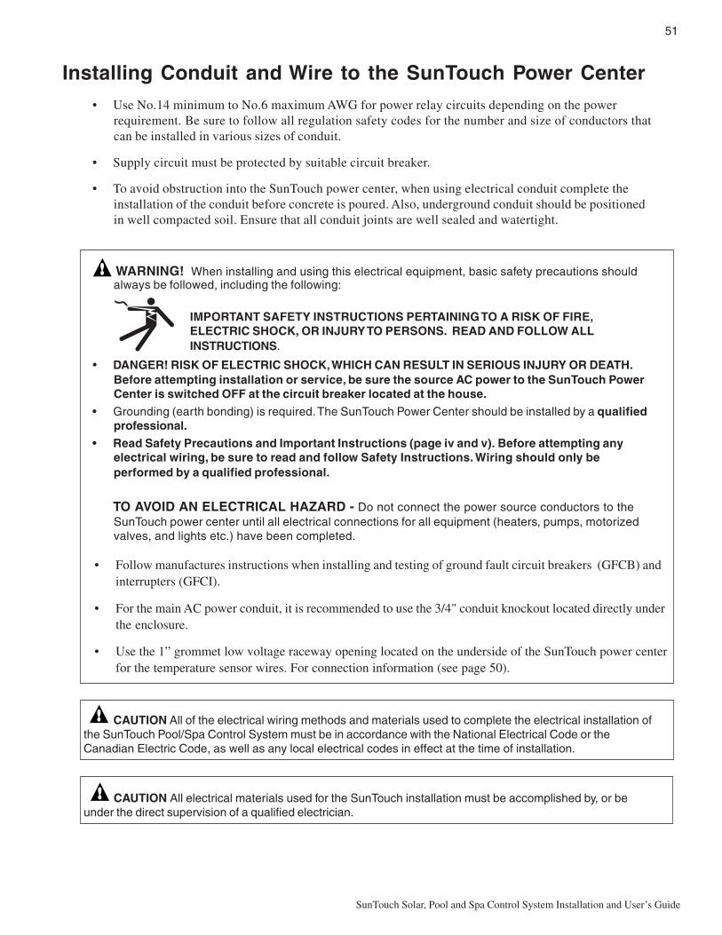
51
SunTouch Solar, Pool and Spa Control System Installation and User’s Guide
Installing Conduit and Wire to the SunTouch Power Center• Use No.14 minimum to No.6 maximum AWG for power relay circuits depending on the power
requirement. Be sure to follow all regulation safety codes for the number and size of conductors thatcan be installed in various sizes of conduit.
• Supply circuit must be protected by suitable circuit breaker.
• To avoid obstruction into the SunTouch power center, when using electrical conduit complete theinstallation of the conduit before concrete is poured. Also, underground conduit should be positionedin well compacted soil. Ensure that all conduit joints are well sealed and watertight.
WARNING! When installing and using this electrical equipment, basic safety precautions shouldalways be followed, including the following:
IMPORTANT SAFETY INSTRUCTIONS PERTAINING TO A RISK OF FIRE,ELECTRIC SHOCK, OR INJURY TO PERSONS. READ AND FOLLOW ALLINSTRUCTIONS.
• DANGER! RISK OF ELECTRIC SHOCK, WHICH CAN RESULT IN SERIOUS INJURY OR DEATH.Before attempting installation or service, be sure the source AC power to the SunTouch PowerCenter is switched OFF at the circuit breaker located at the house.
• Grounding (earth bonding) is required. The SunTouch Power Center should be installed by a qualifiedprofessional.
• Read Safety Precautions and Important Instructions (page iv and v). Before attempting anyelectrical wiring, be sure to read and follow Safety Instructions. Wiring should only beperformed by a qualified professional.
TO AVOID AN ELECTRICAL HAZARD - Do not connect the power source conductors to theSunTouch power center until all electrical connections for all equipment (heaters, pumps, motorizedvalves, and lights etc.) have been completed.
• Follow manufactures instructions when installing and testing of ground fault circuit breakers (GFCB) andinterrupters (GFCI).
• For the main AC power conduit, it is recommended to use the 3/4" conduit knockout located directly underthe enclosure.
• Use the 1” grommet low voltage raceway opening located on the underside of the SunTouch power centerfor the temperature sensor wires. For connection information (see page 50).
CAUTION All of the electrical wiring methods and materials used to complete the electrical installation ofthe SunTouch Pool/Spa Control System must be in accordance with the National Electrical Code or theCanadian Electric Code, as well as any local electrical codes in effect at the time of installation.
CAUTION All electrical materials used for the SunTouch installation must be accomplished by, or beunder the direct supervision of a qualified electrician.

52
SunTouch Solar, Pool and Spa Control System Installation and User’s Guide
BR
OW
N
WH
ITE
BLU
E
BR
OW
N
WH
ITE
BLU
E
BLA
CK
BLA
CK
Transformer Connections
High Voltage Wiring
The high voltage wiring section is located inside the SunTouch enclosure. The SunTouch system can beconnected either to 120 VAC or 240 VAC. The SunTouch system should be wired to receive continuouspower (connect directly to sub-panel). The maximum current rating is 820/410 mA at 120/240 VAC 60 Hz/50Hz.
• For the AC power wire into the SunTouch Power Center from the main circuit breaker at the house, usea three conductor cable. Follow manufactures instructions when installing and testing of ground faultcircuit breakers (GFCB) and interrupters (GFCI).
Connect input AC wires to the SunTouch Power Center transformer wires as follows:
120 VAC: Connect one wire to the Brown/White wires and one wire to the Blue/Black wires. One wiremust be connected to the grounding bar.
240 VAC: Connect one wire to Black wire and one wire to Brown wire. The White/Blue wires areconnected together. One wire must be connected to the grounding bar.
240 VAC 120 VAC
¾" conduit knockout from mainpower supply circuit breaker (No.14 minimum AWG wire)
Three ½"conduitknockouts for relaysand other equipment.
GROUNDING BAR (threeterminals for relays and onefor main AC ground wire)
Transformer wiresand source ACpower wires notshown

53
SunTouch Solar, Pool and Spa Control System Installation and User’s Guide
SunTouch Motherboard ConnectionsThe SunTouch system motherboard is mounted onto the back of the control panel located in the Power Center.The motherboard provides the voltage connections to switch the filter pump, heater, auxiliary relays, motorizedvalves, and connections for temperature sensors. To access the motherboard, refer to “Accessing theSunTouch Motherboard,” on page 54.
Equipment Power• It is recommended to connect the filter pump relay to an independent circuit breaker. Follow
manufactures instructions when installing and testing of ground fault circuit breakers (GFCB) andinterrupters (GFCI).
• A maximum of three (3) power relays can be installed in the SunTouch Power Center. Connectpumps and other high-voltage equipment to the power relays.
SunTouch Motherboard Connections
POOL/SPA - CONNECTS TO FILTER PUMP RELAY
VALV
E AC
TUATO
RS
COM PORT
PLUG INTO AUX 3SOCKET ONSUNTOUCHMOTHERBOARD
PLUG INTOPUMP SOCKETON SUNTOUCHMOTHERBOARD
AUX 2
AUX 1
FILTER PUMP
PLUG INTOPUMP SOCKETON SUNTOUCHMOTHERBOARD
PLUG INTOAUX 2 SOCKETON SUNTOUCHMOTHERBOARD
PLUG INTOAUX 1 SOCKETON SUNTOUCHMOTHERBOARD
INTAKERETURN
SOLAR
AUX 3PUMP
AUX 2AUX 1
VLV
AV
LV B
VLV
C
AUX 1 - CONNECTS TO RELAY
AUX 2 - CONNECTS TO RELAY
AUX VALVE C or SOLAR VALVE ACTUATOR
INTAKE VALVE ACTUATOR
RETURN VALVE ACTUATOR
AUX 3 - HIGH SPEED CONTROL FOR 2-SPEED PUMP (2-SPD RELAY OPTION),SPEED CONTROL FOR INTELLIFLO 4x160or QUICKTOUCH.
ONLY
SOLAR
CLNR
USED FOR "SOLAR ONLY" SYSTEM:- PUMP and AUX 1 CIRCUITS ARE ALWAYS ON WHEN SOLAR IS ACTIVE.
GASHEATER
TRANSFORMERFACTORY WIRINGOUTPUT:
18 VAC 24VAC
RESET
CLEANER: BOOSTER CLEANER PUMP (SOLAR ONLY)
CR2032+3V
120 VAC 120 VAC
J12
J12 IS FOR CONNECTION TO A GAS HEATER ONLY. DO NOT CONNECT TOELECTRIC HEATER OR HEAT PUMP
A
A

54
SunTouch Solar, Pool and Spa Control System Installation and User’s Guide
Accessing the SunTouch MotherboardThe SunTouch motherboard provides connectors for three auxiliary relays, valve actuators and sensors.
To access the SunTouch Power Center electronics compartment:
1. Loosen the retaining screw on the front panel. Open the hinged front panel to access the electronicscompartment.
2. Proceed with:
• Installing Auxiliary Relays, page 55• Installing the Valve Actuator, page 57• Installing and Connecting Temperature Sensors, page 58• Connecting SunTouch to a Gas Heater, page 59
3. After all electrical connections have be completed, close the front panel and secure it with theretaining screw.
Retaining screw
Front panel
SunTouch Power Center (Shared Equipment System)

55
SunTouch Solar, Pool and Spa Control System Installation and User’s Guide
Installing Auxiliary RelaysA maximum of three standard auxiliary relays can be installed in the SunTouch Power Center. Depending onthe SunTouch kit, relays may not be included in the kit. Relays must be installed at the site. When using a 2-Speed pump, the optional 2-Speed relay (P/N 520198) can be installed, replacing the standard relay which islocated in the right-side of the Power Center. For more information about SunTouch kits, see page 40. AllSunTouch high voltage double pole relays are rated at 3HP/30A at 240 VAC (1½ HP/30A at 120 VAC).
Relay locations
A standard relay can be installed in any one of the thee locations provided in the SunTouch Power Center withthe exception of the an optional 2-Speed relay, which can only be installed in the right-side compartment of thePower Center. Power Center relay locations are shown below.
Installing relays
To install a standard relay in the SunTouch Power Center:
1. Standard relay (Location 1): Position the relay coil up in therelay compartment at about a 30 degree angle. Slide the tip ofthe relay flange under head of the left-side screw. Rotate therelay upward to align the right-side flange with the screw hole.Using a 1/4 in nut driver, secure the relay in place with theretaining screw.
Standard relay (Location 2): Position the relay (coil facingupward) in the relay compartment at about a 30 degree angle.Slide the tip of relay flange under head of the left-side screw.Rotate the relay downward to align the right-side flange withthe screw hole. Using a 1/4 in nut driver, secure the relay inplace with the retaining screw.
Relay Test button: For testing relay connectivity, with powerapplied, press the lever on the top (line/load side) of the relay.
Standard or2-Speed relay(Location 3)
Standard relay(Location 2)
Standard relay(Location 1)
Emergency Shut-Off Switch(ESO) circuit board
(optional)
Three ½"conduit knockouts for relay wires(14 minimum to 6 maximum depending onthe load)
Slot for relay cables
Screwhead
Flange
Relay (Location 1)
Relay (Location 2)
Line 1/Load 1
Line 2/Load 2
Test button

56
SunTouch Solar, Pool and Spa Control System Installation and User’s Guide
Installing relays (Continued)
Standard relay (Location 3): Position the relay (coil facing upward) on top of the mounting studs.Align the relay flanges with the screw holes. Using a 1/4 in nut driver, secure the relay in place withthe two retaining screw.
2-Speed Relay (location 3): Position the relay bracket on top of the mounting studs. Align thebracket with screw holes. Using a 1/4 nut driver, secure the bracket with the two retaining screws.Insert the relay (coil facing to the right-side) into the relay bracket and snap in place.
2. Route the relay cable into the slot between the low voltage compartment and the transformercompartment to the SunTouch motherboard.
Note: If there is an Emergency Shut-Off Switch (ESO) circuit board installed in the SunTouchPower Center, connect the relay wires to the ESO circuit board. For more information, see“Emergency Shut-Off Switch Installation,” on page 73.
3. Connect the relay plugs onto the PUMP, AUX 1 or AUX 2 two-pin socket on the motherboard.
2-SPEED RELAY CONNECTION: The 2-Speed relay cable plug is connected to AUX 3 which controls thepump’s high speed output. The AUX 3 circuit output can only be used to control the following:2-Speed pump relay, one of the four speeds (RPM) of an IntelliFlo VS pump or the flow rate (GPM)of an IntelliFlo VF pump. For installation and operation information, refer to the Two-Speed RelayUser’s Guide (P/N 520210).
Note: The IntelliChlor and IntelliFlo pump does not require a relay connection, it connects tothe COM Port (J11) connector on the SunTouch notherboard.
Note: For SunTouch motherboard wiring connections, refer to “SunTouch MotherboardConnections,” on page 53.
Mounting studs forrelay screws
Bracket
Insert 2-Speedrelay into
bracket
Mounting studs forrelay screws

57
SunTouch Solar, Pool and Spa Control System Installation and User’s Guide
Installing Valve ActuatorsFor shared equipment systems there are two motorized valve actuators (CVA-24T, P/N 263045) included withthe SunTouch kit.
To install a valve actuator:
1. Remove the valve knob, handle and the four screws, from the valve cover (indicated with arrows).
2. Align the splines of the actuator shaft over the shaft of the valve.3. If the actuator is not aligned with the mounting holes on the valve cover, rotate the actuator (while
still attached to the valve) until the actuator is positioned correctly over the valve.
4. Secure the actuator with the screws provided. Only use self-tapping screws when required.
5. Mount the valve handle and knob onto the actuator.
6. At the SunTouch Power Center, route the cable up through the 1” grommet and low voltage racewayto the motherboard (see page 43).
7. Connecting of valve actuators to the SunTouch Motherboard (see page 53):- Connect VALVE A cable plug into the IN-TAKE (suction) 3-pin socket.- Connect VALVE B cable plug into the RETURN 3-pin socket.
Note: For more information, see Item 2 and 3 of Plumbing requirements on page 43•1. Excesscable can be coiled in the SunTouch enclosure low voltage raceway. Do not coil the wire inupper low voltage compartment.
For Solar Heating: Use VALVE C for a solar valve actuator when solar heating is being used.
Adjusting the valve positionIf the valve rotates to the wrong position, adjust the switch on the back of the actuator between ON1and ON2 positions. This will rotate the valve to the correct position. The following diagram shows thestandard plumbing and valve actuator position.
Screw
Valve actuator
Screw
Screw
OUT (Valve A - Suction) IN (Valve B - Return)
ININ OUT OUT▼
▼ ▼
▼

58
SunTouch Solar, Pool and Spa Control System Installation and User’s Guide
Installing and Connecting Temperature SensorsWater Temperature Sensor
To install the water sensor:
1. Select a convenient location to mount the water sensor in the plumbing system between the filterpump and filter. Drill a 5/16" diameter hole in one side of the pipe,
2. Insert tip of sensor into the hole. Use the band clamp to secure the sensor to the pipe. Tighten theclamp just enough so that the o-ring begins to flatten. Do not overtighten
3. Run 22-gauge two-conductor cable (included) between the sensor SunTouch motherboard. Route thewire up through the low voltage raceway to the motherboard.
4. Fasten the cable to the plumbing with cable ties.
5. Cut off the excess wire and the strip conductors ¼ inch. Use waterproof connectors (provided) toconnect the sensor to cable. Insert the wires into the WATER SENSOR screw terminals (J9) onright-side of the motherboard. For SunTouch motherboard wiring connections, refer to “SunTouchMotherboard Connections,” on page 53.
Ambient Air Temperature Sensor (for freeze protection)The SunTouch system will automatically detect an installed air sensor to protect the system if freezingconditions occur. By default, the air sensor is always ON. Freeze protection for a “Solar Only” systemrequires an additional air sensor (P/N 520272). To disable the air sensor, see “Advanced Menu (8/14): AirSensor” on page 24.
To install the air sensor:
1. To avoid freeze damage to pool and spa equipment, mount the sensor on a flat surface in a shadedarea, in the open air, to assure proper temperature readings. If possible, mount the sensor near theSunTouch power center. The SunTouch main screen displays the current ambient air temperature.
2. Route the wire through the low voltage raceway to the motherboard in the power center.
3. Cut off the excess wire and the strip conductors ¼ in. Insert the wires into the AIR screw terminals(J9) on right side of the motherboard.
Solar Temperature Sensor Freeze protection for a “Solar Only” system requires an additional air sensor (P/N 520272). To disable the airsensor, see “Advanced Menu (8/14): Air Sensor” on page 24. Run a two-conductor cable between the sensorand the SunTouch power center. The maximum sensor cable length is 300 ft from the SunTouch power center.
To install the solar sensor:
1 Mount the sensor on a flat surface, with the same exposure to sun as the solar collectors (next to thecollectors is recommended) or any sunny location. Do not let the sensor touch the panels.WARNING: DO NOT DRILL HOLE AND CLAMP SENSOR INTO SOLAR PIPE. Forglazed panels, install the sensor between collector and glazing.
2 If necessary, splice a two-conductor extension wire to the sensor. Run two-conductor cable betweenthe sensor and the SunTouch Power Center. Use waterproof connectors to connect the sensor to thecable. Use twisted pair 20 AWG outdoor rated sensor wiring and be sure the wire connections areprotected from the environment. Use shielded cable for long runs (300 ft. total wire length maximum)or runs near other electrical wiring.
3 Strip the conductors ¼ in. Insert the wires into the SOLAR SENSOR screw terminals (J9) on rightside of the motherboard.

59
SunTouch Solar, Pool and Spa Control System Installation and User’s Guide
Connecting SunTouch to a Gas HeaterThe SunTouch motherboard provides a set of low voltage dry contacts that can be connected to most gasheaters and heat pumps. Refer to your heater documentation for specific wiring instructions for connecting theheater to an external control (typically using a two-wire remote control connection).
Note: SunTouch motherboard heater screw terminals (J12) can be used for high voltage connection nothigher than 24 VAC or VDC current for electric heaters or heat pumps.
Connecting to a standard heater
The following installation instructions are for gas heaters and heat pumps with low voltage thermostats.
To connect a standard heater to SunTouch:
1. Switch the power OFF to the heater.
2. Run a two-conductor cable from the heater thermostat area to the low voltage raceway to themotherboard in the SunTouch Power Center. Use 105° C temperature rated wire for connection tothe heater. When connecting wires inside the heater, be cautious of HOT internal parts of the heater.Refer to the heater owners manual for the manufacturer’s recommendations for the minimumtemperature rating for wires.
3. Strip the conductors ¼ in. Insert the wires into the GAS HEATER two-screw terminals (J12) on themotherboard. For SunTouch motherboard wiring connections, refer to “SunTouch MotherboardConnections,” on page 53.
4. At the heater, connect the wires in accordance with heater manufacturer’s instructions. For olderheaters without instructions for remote operation, connect the wires to the “Fireman’s Switch”connections in series with the thermostat, pressure switch, and other safety switches.
5. Do NOT disconnect or wire around the thermostat, pressure switch, high limit switch, or other safetydevices.
6. Switch ON the main power switch of the heater. Note, SunTouch does not control the AC power tothe heater.
7. Set the heater thermostat to the maximum hottest setting.
8. From the SunTouch menu (see page 26): Goto Main Menu 10/14 “Circ Functions” and assignAUX 1 or AUX 2 to “HEATER.”
Connecting to a Pentair Water Pool and Spa® MiniMax®, MasterTemp® Gas HeaterTo connect a MiniMax, or MasterTemp heater to the SunTouch power center:
1. Switch the power OFF to the heater.
2. Remove the factory installed jumper from the “Ext Switch” connector.
3. Connect the two-wire cable from J12 on the SunTouch motherboard to the “Ext Switch” terminal.CAUTION: Be sure that the wires from the heater to the SunTouch Power Center are not nearor touching any line voltage wires in the heater. Failure to follow these instructions may causethe heater to malfunction.
4. Set the Power (Thermostat Select) switch to either “Pool” or “Spa.”
5. Set the “Pool” and “Spa” thermostats to their maximum position.
6. From the SunTouch menu (see page 26): Goto Main Menu 10/14 “Circ Functions” and assignAUX 1 or AUX 2 to “HEATER.”

60
SunTouch Solar, Pool and Spa Control System Installation and User’s Guide
Connecting to a Sta-Rite® Gas HeaterTo connect a StaRite heater to the SunTouch power center (including MaxiTherm® heater):
1. Switch the power OFF to the heater.
2. Remove the upper jacket and open the control box.
3. Remove the jumper for the “Fireman’s switch.”
4. Connect the two-wire cable from J12 on the SunTouch motherboard to the “Fireman’s Switch”connector block. Use 105° C temperature rated wire for connection to the heater. When connectingwires inside the heater, be cautious of HOT internal parts of the heater. Refer to the minimumtemperature rating for wires recommended by the manufacturer. See the heater owners manual fordetails.
5. Switch ON the main power toggle switch of the heater. Note, SunTouch does not control the ACpower to the heater.
6. Set the heater thermostats to the maximum position.
7. From the SunTouch menu (see page 26): Goto Main Menu 10/14 “Circ Functions” and assignAUX 1 or AUX 2 to “HEATER.”
Connecting to a Standard Heat Pump or Electric HeaterTo connect a standard heat pump the SunTouch power center:
1. Switch the power OFF to the heater.
2. Remove the factory installed jumper from the “Ext Switch” connector.
3. Connect the two-wire cable from J12 on the SunTouch motherboard to the “Ext Switch” terminal.CAUTION: Be sure that the wires from the heater to the SunTouch Power Center are not nearor touching any line voltage wires in the heater. Failure to follow these instructions may causethe heater to malfunction.
4. Set the Power (Thermostat Select) switch to either “Pool” or “Spa.”
5. Set the “Pool” and “Spa” thermostats to their maximum position.
6. From the SunTouch menu (see page 26): Goto Main Menu 10/14 “Circ Functions” and assignAUX 3 Circuit to “HEATER.”

61
SunTouch Solar, Pool and Spa Control System Installation and User’s Guide
SunTouch Solar System Installation• To ensure maximum flow of water through the solar panels, a solar booster pump should be added if
panels are installed at a very high elevation.
• It is recommended that the solar panels are mounted in a way that gravity will allow drainingwhenever the filter pump is not on.
• For systems with glazed panels, damage can occur from overheating if the filter pump is still runningafter the solar has turned off. To enable glazed panels to automatically drain whenever the solar turnsoff (even if the filter pump is still running), a 1/2" motorized solar drain valve should be plumbed fromthe solar feed line, through a check valve, to a zero psi point (such as pool fill line or jet air intake).
SunTouch Solar System Start-Up
1. Switch power on to the SunTouch Power Center.
2. If pool cleaner protection has been added to the system, the pool cleaner pump motor should beactivated whenever the pool cleaner timer is on. Momentarily turn pool cleaner on and off to checkthe motor is operating correctly.
3. Check that Solar Valve is in “solar bypass” position, diverting water away from solar panels. If SolarValve is staged incorrectly (diverting water to the solar panels), reverse switch on back of ValveActuator (change from ON1 to ON2, or vice-versa). The Valve Actuator will automatically rotate tothe correct position.
4. Check that Solar Valve has rotated from the “solar bypass” position to the “solar” position, divertingwater through the solar panels.
5. The system is now ready to be operated as desired.
Pool Cleaner Protection
Recommended for use in pool systems which utilize a “booster pump” pool cleaner. This feature automaticallyturns off the pool cleaner pump for a few minutes whenever solar is initiated. This will protect the pump fromdamage caused by air in the solar panels at system start-up.

62
SunTouch Solar, Pool and Spa Control System Installation and User’s Guide
SunTouch Pool/Spa Controller System Start-UpPerform the following start-up procedures to ensure that the SunTouch enclosure is installed correctly.
Before you power up the SunTouch enclosure check the following:
Check Electronics
Check that the following plugs are seated correctly on the motherboard:
• Relay connectors - PUMP - AUX1 - AUX2
• Temperature sensors connectors WATER, SOLAR, AIR (J9)
• Transformer wire harness (J10) attached to the motherboard.
• Heater control connector GAS HEATER (J12) or two-wire screw terminal.
Refer to "Summary System Installation Steps Summary," on page 37, and "SunTouch MotherboardConnections on page 51.
SunTouch System Test
The following describes how to test the main control panel to activate the heater, valves and pumps. Beforetesting the system, be sure that all pool and spa equipment has been properly installed and connected to theSunTouch enclosure.
Testing Valve Actuators and Filter Pump
Use the following steps to test the valve actuators (CVA24T - P/N 263045) for proper rotation.
To test the valve actuators and pool/spa filter pump:
1. Power up the SunTouch Power center.
2. Press the MENU button. Circuit On/Off is displayed. Press the Right arrow button access the poolfilter pump circuit. Press the Up or Down arrow button and select ON. Press the Left arrow buttonto return to the main status screen. POOL and the temperature setting will be displayed as shownbelow.
3. The pool filter pump should be operating. Water will be removed from the pool and returned to thepool.
Testing the auxiliary relays
To verify that AUX 1, AUX 2 and AUX 3 relays outputs are operating correctly:
1. Power up the SunTouch Power center.
2. Press the MENU button. Circuit On/Off is displayed. Press the Right arrow button access the AUX1 setting. Press the Up or Down arrow button and select ON. Press the Left arrow button to returnto the main status screen. The auxiliary number will be displayed as shown below.
3. Repeat step 2 to test AUX 2 and AUX 3 relay.
AIR 71°F11: 51AM AUX123
POOL 71°F / 91°F11: 51AM HEATER
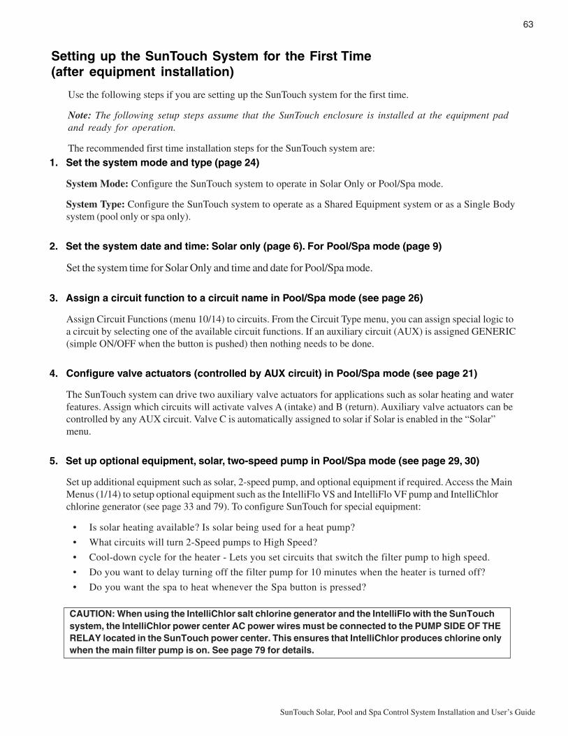
63
SunTouch Solar, Pool and Spa Control System Installation and User’s Guide
Setting up the SunTouch System for the First Time(after equipment installation)
Use the following steps if you are setting up the SunTouch system for the first time.
Note: The following setup steps assume that the SunTouch enclosure is installed at the equipment padand ready for operation.
The recommended first time installation steps for the SunTouch system are:
1. Set the system mode and type (page 24)
System Mode: Configure the SunTouch system to operate in Solar Only or Pool/Spa mode.
System Type: Configure the SunTouch system to operate as a Shared Equipment system or as a Single Bodysystem (pool only or spa only).
2. Set the system date and time: Solar only (page 6). For Pool/Spa mode (page 9)
Set the system time for Solar Only and time and date for Pool/Spa mode.
3. Assign a circuit function to a circuit name in Pool/Spa mode (see page 26)
Assign Circuit Functions (menu 10/14) to circuits. From the Circuit Type menu, you can assign special logic toa circuit by selecting one of the available circuit functions. If an auxiliary circuit (AUX) is assigned GENERIC(simple ON/OFF when the button is pushed) then nothing needs to be done.
4. Configure valve actuators (controlled by AUX circuit) in Pool/Spa mode (see page 21)
The SunTouch system can drive two auxiliary valve actuators for applications such as solar heating and waterfeatures. Assign which circuits will activate valves A (intake) and B (return). Auxiliary valve actuators can becontrolled by any AUX circuit. Valve C is automatically assigned to solar if Solar is enabled in the “Solar”menu.
5. Set up optional equipment, solar, two-speed pump in Pool/Spa mode (see page 29, 30)
Set up additional equipment such as solar, 2-speed pump, and optional equipment if required. Access the MainMenus (1/14) to setup optional equipment such as the IntelliFlo VS and IntelliFlo VF pump and IntelliChlorchlorine generator (see page 33 and 79). To configure SunTouch for special equipment:
• Is solar heating available? Is solar being used for a heat pump?
• What circuits will turn 2-Speed pumps to High Speed?
• Cool-down cycle for the heater - Lets you set circuits that switch the filter pump to high speed.
• Do you want to delay turning off the filter pump for 10 minutes when the heater is turned off?
• Do you want the spa to heat whenever the Spa button is pressed?
CAUTION: When using the IntelliChlor salt chlorine generator and the IntelliFlo with the SunTouchsystem, the IntelliChlor power center AC power wires must be connected to the PUMP SIDE OF THERELAY located in the SunTouch power center. This ensures that IntelliChlor produces chlorine onlywhen the main filter pump is on. See page 79 for details.

64
SunTouch Solar, Pool and Spa Control System Installation and User’s Guide
6. Configuring the heater system options Pool/Spa mode (page 14)
Set the type of heat source being used (Heater, Solar, Solar Preferred).
7. Configure the QuickTouch wireless remote buttons (page 28)
Assign four circuits to the QuickTouch remote buttons. Once you have checked that all buttons operateproperly, place labels on remote buttons.
8. Schedule on/off times for circuit (page 17)
Set times for automatic circuit activation. Up to 6 total programs can be created for all circuits combined.One circuit can have up to a maximum of 4 programs (4/4). All user created programs are active all the time;so check that there are not conflicting automated times.

65
SunTouch Solar, Pool and Spa Control System Installation and User’s Guide
Section 3Troubleshooting
Troubleshooting
Use the following troubleshooting information to help resolve problems that may occur when using theSunTouch system. If by following the recommended actions you are still unable to resolve the problems, pleasecontact Technical Support (see page vi).
Frequently Asked Questions (FAQ)
How do I setup a two-speed pump?
A two-speed pump operates using two relays and one or more circuits. The first relay turns the pump on oroff. Assuming this is a filter pump, this circuit is controlled by the pool and spa circuits or any other circuit thatmay be tied to the filter pump (such as circuits with freeze protection, etc.). The second relay (AUX 2)switches the pump from low speed to high speed. The default condition is low speed. Up to three circuits maybe assigned to trigger the pump to high speed. However, if three relays are being used, two relays must belocated outside the SunTouch enclosure. The SunTouch enclosure which houses two relays. Note: Thesecircuits do not switch the pump on.
To configure a two-speed pump relay, refer to “Settings Menu: 2-Speed Pump,” on page 29. For relay locationand wiring (see page 53). The 2-Speed pump relay connector is plugged into the AUX 3 output socket on theSunTouch motherboard.
Can I switch the heater on and change the temperature from the spa?
The heater may be switched on from the spa location using the QuickTouch wireless remote controller(optional), see page 28 for setup details.
How do I switch on solar heating?
The system must first be configured for solar heating. Go to the “Heat” menu (see page 14) and enable“Solar” as the heat source. Note: Do not select “Heat Pump” as the solar heating method.

66
SunTouch Solar, Pool and Spa Control System Installation and User’s Guide
Self Test Error Codes
The “Self Test” feature is intended for use by service personnel. If after performing a control panel self test(see Diagnostics menu page 25) there were no errors detected, Code 0 is displayed, indicating that there wereno problems and the test was successful. If a problem is detected during the test, an error code is displayedupon completion of the test. For example Code 1 would indicate a problem with the display. If multiple errorsare detected, multiple code numbers are displayed. For example, Codes 4, 2, 1, would indicate problemsdetected with the buttons, LCD contrast, LCD backlight on the control panel.
The following lists the control panel self test error codes.
Error Code Table
SunTouch Error Messages
Error Messages
If the system detects that a sensor is not connected to the SunTouch Power Center or it is defective, an errormessage is displayed in the Diagnostics menu (page 25). The following lists the sensor errors.
egasseMrorrE esuaCelbissoP noituloS
niaMehtnosyalpsiD(rrEriA)neercS
ehtotdetcennoctonrosnesriA.draobrehtomhcuoTnuS
12JotdetcennocsigulprosnesriaehttahtkcehCrosnesehttahtkcehC.draobrehtomehtnorotcennoc
.ylreporpdetcennocsieriw
nisyalpsiD(rrEerutarepmeTriA)unem"scitsongaiD"eht
ehtotdetcennoctonrosnesriA.draobrehtomhcuoTnuS
12JotdetcennocsigulprosnesriaehttahtkcehC.draobrehtomehtnorotcennoc
syalpsiD(rrEerutarepmeTretaW)unem"scitsongaiD"ehtni
otdetcennoctonrosnesretaW.draobrehtomhcuoTnuSeht
12JotdetcennocsigulprosnesretawehttahtkcehC.draobrehtomehtnorotcennoc
syalpsiD(rrEerutarepmeTraloS)unem"scitsongaiD"ehtni
otdetcennoctonrosnesraloS.draobrehtomhcuoTnuSeht
12JotdetcennocsigulprosnesralosehttahtkcehC.draobrehtomehtnorotcennoc
edoCrorrE noitpircseD
0edoC sahlenaplortnocehT-SSAPsmelborpon
1edoC thgilkcabDCL
2edoC tsartnocDCL
4edoC )snottub(hctiwS
5edoC tsetkcabpoolTRAU
Resetting the System Fuses
The SunTouch Power Center provides two resettable fuses to protect the 18 VAC and 24 VAC circuits. Thefuses are located on the front panel of the SunTouch Power Center. Press the fuse button to reset the fuse. Seepage 40 for fuse locations.

67
SunTouch Solar, Pool and Spa Control System Installation and User’s Guide
Problem Solving a Solar SystemSunTouch solar is not operating
Verify the circuit breaker at sub-panel is not tripped. If the 3 AMP Circuit Breaker on the on SunTouch istripped, it is most often due to a defective Circuit Board or Valve Actuator. Try disconnecting each oneseparately to determine which one is at fault.
Solar will only operate when the solar temperature is 6° warmer than the water temperature.
Inspect the appropriate sensor cable and wire connections and replace the appropriate temperature sensor ifnecessary. An ohm meter can be used to take a reading of the sensors. See table on page 68.
If the temperature sensors are not at fault, replace the SunTouch circuit board.
Water flow to panels switch does not operate the valve actuator
If the valve actuator does not operate when using the WATER FLOW TO PANELS Switch (sliding switchbetween ON and OFF), either the valve actuator or the SunTouch circuit board is at fault.
First verify that the toggle switch located on the valve actuator is either in the ON1 or ON2 position.
With a voltmeter, check the output voltage of the VLV1 socket located on the SunTouch circuit board. Whenthe WATER FLOW TO PANELS Switch is in the OFF position, the top and middle pins should read 24 VAC.When the WATER FLOW TO PANELS switch is in the ON position, the top and bottom pins should read24 VAC.
If voltage readings are correct, replace the valve actuator. If voltage readings are incorrect, replace theSunTouch circuit board.
Checking The Temperature Sensors
Disconnect temperature Sensor wires from the SunTouch circuit board, and test sensor using an ohm meter.See table on page 66.
Testing the Solar System
To test the SunTouch in “SOLAR ONLY” mode: Set the “System Control” menu setting to “SOLAR ON”verify the valve(s) are in the solar position. Then set the menu setting to “SOLAR OFF” and verify the valve isin the normal recirculating pool position. If the valve(s) positions are working in reverse, toggle the valveswitches and test again.
Air Sensor ERROR
If after enabling the optional air sensor (see page 24) the main screen displays AIR Error or Solar SensorERR, this indicates the solar sensor is not connected or it is out of range. Check that the sensor is connectedcorrectly to connector J9 on the SunTouch motherboard (see page 53).

68
SunTouch Solar, Pool and Spa Control System Installation and User’s Guide
oC oF ΩΩΩΩΩ oC oF ΩΩΩΩΩ
-26 -15 139,300 16 60 15,310-25 -13 130,300 18 65 13,480
-23 -10 118,000 21 70 11,880
-21 -5 100,200 24 75 10,500
-20 -4 97,000 25 77 10,000
-18 0 85,350 27 80 9,298
-15 5 72,910 29 85 8,250
-12 10 62,480 30 86 8,056
-9 15 53,640 32 90 7,331
-10 14 55,300 35 95 6,530
-7 20 46,230 38 100 5,826
-5 23 42,300 40 104 5,326
-4 25 39,910 41 105 5,209
-1 30 34,560 43 110 4,663
0 32 32,600 45 113 4,367
2 35 30,000 49 120 3,757
4.7 40 26,100 50 122 3,602
5 41 25,400 52 125 3,381
7 45 22,760 54 130 3,047
10 50 19,900 55 131 2,985
13 55 17,440 57 135 2,750
15 59 15,700
Temperature vs. Resistance Data
SunTouch systems use 10k Ωαττ thermistor sensors. When the solar sensor is disconnected from theSunTouch system, the sensor will read 10k Ω at 77º F (25ºC). Refer to the following table for the resistance atother temperatures. An accurate reading should give a temperature setting that is accurateto ±0.2º C from 0 to 70 º C.
Temperature Resistance Temperature Resistance

69
SunTouch Solar, Pool and Spa Control System Installation and User’s Guide
System Problem Diagnosis
Use the following information to resolve system problems.
Problem: SunTouch LCD fails to operate.
motpmyS esuaCelbissoP noituloS
onsaherusolcnehcuoTnuS,sDELon,knalb,neercs(-rewop
.)gnikrowtonsnottub
morfnurgniriwdaBlortnoCroodtuO
ehtnidraobrehtom/lenaP.retneCdaoL
nI.nekorberasnoitcennoconerusnednaelbacyfireVehT.noitalusniehtrednunekorbsieriwasesacemos
tcepsuseraelbacrotcudnocruofehtfoseriwretnecowt)wolleYdnaneerG(
DCLlenaplortnochcuoTnuSetarepootsliaftub,pusthgil
.yltcerroc
gniriw/elbaCevitcefeD yfireV elbac nI.nekorberasnoitcennoconerusnednaehT.noitalusniehtrednunekorbsieriwasesacemos
tcepsuseraelbacrotcudnocruofehtfoseriwretnecowt)wolleYdnaneerG(
egasseMsutatS esuaCelbissoP noituloS
SRORREON-KO lamronrolhCilletnI.edomgnitarepo
A/N
ETANIROLHCREPUS repuS"nisirolhCilletnI42rofedom"noitanirolhC
.sruoh
23egapees(edomnoitanirolhCrepuS“nisirolhCilletnI)sliatedrof
RORREKNILMOC noitacinummocrolhCilletnIhcuoTnuShtiwrorre
.draobrehtom
.draobrehtomhcuoTnuSotrolhCilletnImorfelbackcehC
BCP/WOLFKCEHC rolhCilletnIkcehC.lleccitylortcele
gnitoohselbuortediuGs’resUrolhCilletnIotrefeR.noitamrofni
TLASWOL .retawloopottlasddA .mpp0092dnampp0052neewtebsileveltlasretawehTataenirolhcecudorpoteunitnoclliwrolhCilletnIehT
.sliatedrofediuGs'resUrolhCilletnIeeS.leveldecuder
TLASWOLYREV .loopnitlashguonetoN repstrap0052wolebnellafsahleveltlasretawehTlitnuenirolhcecudorptonlliwrolhCilletnI.)mpp(noillims'resUrolhCilletnIeeS.yllaunamdeddasitlaslanoitidda
.sliatedrofediuG
TNERRUCHGIH rolhCilletnIkcehC.lleccitylortcele
otrefeR.rellortnoclleccitylortcelerolhCilletnIkcehC.noitamrofnignitoohselbuortediuGs’resUrolhCilletnI
!!LLECNAELC pudliubmuiclacsahlleC.gninaelcseriuqerdna
otrefeR.gninaelcseriuqerdnapudliubmuiclacsahlleC.snoitcurtsnigninaelcrofediuGs’resUrolhCilletnI
EGATLOVWOL rolhCilletnIkcehC.lleccitylortcele
gnitoohselbuortediuGs’resUrolhCilletnIotrefeR.noitamrofni
IntelliChlor Error Messages
IntelliChlor status and error messages are displayed in the “Chlorinator” menu (see page 32). Use thefollowing information to resolve IntelliChlor system problems. To access the IntelliChlor menu, pressMenu > Diagnostics > Chlorinator.

70
SunTouch Solar, Pool and Spa Control System Installation and User’s Guide
Problem: The Quick Touch remote will not work, or will not work dependably.
motpmyS esuaCelbissoP noituloS
fforononrutotsmeestinU/resuehttuohtiwstiucric
rettimsnart
siemohybraenAralimisagnitarepo
tinusseleriw
dnarettimsnartehtrofedocsserddaetanretlanatceleSreviecsnarThtobnosehctiwsPIDehtegnahC.reviecer
.gnittesgnihctamtub,etanretlanaotetomerdna
tnempiuqesnrutylbadnepedtinUsitnempiuqeecnotub,NO
ylbadnepedtonseodtigninnursiegnarro,FFOtnempiuqenrut
tnempiuqenehwdecuderyltaerggninnursi
siesionlacirtceleeudnUroenoybdecudorpgniebtnempiuqefoseceiperom
ehtotytimixorpesolcni.reviecer
sahcustnempiuqemorfyawarevieceRehtetacoleRtahtnoitacolanireviecerehtetacoleR.srotomrewolb
resuehtaeraehtotsnoitcurtsborewefsedivorp.rettimsnartehtsetarepoylnommoc
yltaergsahtub,setarepotinUroirpotderapmocegnardecuder
noitcnuf
siyrettaBrettimsnarT.gniliaf
.)V32302epyt(yrettabrettimsnarTecalpeR
motpmyS esuaCelbissoP noituloS
nothgiltonseodDELREWOPehtnidetacoldraobrevieceReht
.llehsmalccitsalp
retneCdaoLhcuoTnuSrewopevahtonseod
rewopehttahtdnadeilppusgniebsirewoperusnEdellatsnireviecerehttuohtiwyltcerrocsetareporetnec
roelbacevitcefeDdaoLehtotnoitcennoc
retneC
elbacdoognwonkgnisudraobehtfonoitcnufehtyfireVgniriwllakcehC.tes
draobrevieceRevitcefeD troppuSlacinhceTtcatnoC
thgiltonseodDELKNILMMOCDELnoitarepolamronnI.knilbrosdnoces2yrevetsaeltaknilblliw
roelbacevitcefeDdaoLehtotnoitcennoc
retneC
elbacdoognwonkgnisudraobehtfonoitcnufehtyfireVtes
draobreviecerevitcefeD draobreviecerecalpeR
yltcerrocnierasehctiwssserddAderugifnoc
sserddaehttahtyfireVehtnosehctiws
dlehdnahdnarettimsnarttcerroceradraobreviecer
hctamdna
deliafsahyrettabrettimsnarT
rettimsnarTecalpeRyrettab
revieceRrorettimsnarTevitcefeD
stiucricemostub,snoitcnuftinUehtetareporo,krowtonod
tiucrictcerrocni
noitarugifnochcuoTkciuQtcerrocnisi
snottubputesot82egapeeS
otsliafro,etarepootsliaftinUegnartaylbadnepedetarepo
esionlacirtceleevissecxE lacirtcele"ysion"morfyawareviecerehtetacoleRsrotomrewolbsahcustnempiuqe
snoitcurtsboynamooTrettimsnartehtneewteb
reviecerdna
dnalatemdnuorgmorfyawareviecerehtetacoleRsnoitcurtsbo
raenootsitinurevieceRdnuorgeht
neewtebecnatsidehtezimixamotreviecerehtetacoleRdnuorgehtdnaannetnareviecereht

71
SunTouch Solar, Pool and Spa Control System Installation and User’s Guide
• Power: 95 VAC to 135 VAC, 0.82 AMP 50/60 Hz or 192 VAC to 288 VAC, 0.41 AMP 50/60Hz• Valve Actuator Output: 24VAC, 50/60 Hz. 0.65 AMP maximum (3 pin connector)• Relay Outputs: 3HP@240V, 1.5HP@120V, booster pump, pool sweep interlock, filter pump or lights.
Three (3) relays provided.• Sensors (thermistor type, 10K W 77° F (25° C). Two sensors required for solar and pool temperatures.
Freeze protection requires an additional sensor for air temperature.• Start Temperature Differential (Solar): 3° - 9°• Stop Temperature Differential (Solar): 2° - 5°• Set Temperature limit: 40° F to 104° F (4° C to 40° C) calibrated scale• Freeze Protection: On at 35° F, off at 38° F
SunTouch Specifications
IntelliFlo VS and IntelliFlo VF Warning and Alarm Conditions
The IntelliFlo VS and IntelliFlo VF alarms and warnings are indicated by flashing LEDs on the control panel.For example, if a “Drive Temperature” warning occurs, the LED will blink two times, then Off, then blink twotimes. This sequence is repeated until the condition is cleared.
• Warning condition: If a warning condition occurs the pump will continue to run but at a reducedspeed. The Green LED executes a sequence of blinks to indicate which alarm or warning hasoccurred.
• Alarm condition: If an alarm condition occurs the pump will stop running. The red LED flashescontinuously to indicate the presence of an alarm. The alarm LEDs will reset when the conditionclears.
See “Pump” Main Menu (12/14) on page 29 for setup information. For IntelliFlo pump troubleshootinginformation, see the IntelliFlo VS Installation and User’s Guide (P/N 357269) and IntelliFlo VF Installation andUser’s Guide (P/N 350075).
Alarm and warning LED sequence
ehtemitforebmuNknilblliwDEL
mralA noitpircseD noitcA
2 gninraWerutarepmeTevirD erutarepmetevirdevissecxE sahnafrotomehterusnE.1.noitalitnevrofaeraetauqeda
.loocotwolladnarotompotS.2
otdeepsrehgihatarotomnuR.3.wolfriagniloocevorpmi
5 mralanwonknU eruliafnortcelE .pmupteserotrewopelcyC.1.evirdecalpeR.2
6 mralAerutarepmeTevirD erutarepmetevirdevissecxE sahnafrotomehterusnE.1.noitalitnevrofaeraetauqeda
otdeepsrehgihatarotomnuR.2.wolfriagniloocevorpmi
7 mralAtuOrewoP wolegatlovylppuS .egatlovylppusreporperusnE
8 mralAtnerrucrevO tnerrucevirdevissecxE lacinahcem/diulfenimaxE.1.daolrevofoecruosrofmetsys
dnarotomezigrene-eD.2.yleerfsnipsrotomfienimreted
.evirdecalpeR.3
9 mralAegatlovrevO ssubevirdnoegatlovevissecxE sdeepsneewtebgnihctiwsdipaR.1segatlovevissecxeesuacnac
.ssubCDs'evirdehtno.egatlovylppusreporperusnE.2

7 2
SunTouch Solar, Pool and Spa Control System Installation and User’s Guide
Wiring SunTouch to the IntelliChlor Salt Chlorine Generator
Be sure to check the wire color and function of the IntelliChlor salt chlorine generator before connecting it tothe SunTouch COM port on the motherboard. See the wiring table below for the pin configuration.
Failure to wire the salt chlorine generator properly can permanently damage the SunTouch system or chlorinegenerator. For more information about wiring IntelliChlor to the SunTouch power center, see page 79. See“IntelliChlor” Main Menu (13/14) on page 33 for setup information.
daoL®ydnaJro®drawyaHgniriwtropMOCretneC
noitcennocroloc
noipircseD enirolhCtlaSrolhCilletnIrotareneG
DER CDV51+ DER
WOLLEY ATAD+ KCALB
NEERG ATAD- WOLLEY
KCALB DNUORG NEERG
gniriwtroPMOChcuoTnuSnoitcennocroloc
noipircseD MOCretneCrewoProlhCilletnItroP
DER CDV51+ DER
WOLLEY ATAD+ WOLLEY
NEERG ATAD- NEERG
KCALB DNUORG KCALB
Wiring Description(Hayward® or Jandy® Load Center COM Port)
Wiring Description(SunTouch COM Port to IntelliChlor Power Center COM Port)
IntelliChlor AC Wiring Instructions: When using an IntelliChlor salt chlorine generator with theSunTouch system, the IntelliChlor AC power center wires must be connected to the PUMP SIDE OF THEMAIN FILTER PUMP RELAY (LOAD SIDE) located in the SunTouch power center. This ensures theIntelliChlor cell produces chlorine only when the main filter pump is on (see page 73 and 74).

73
SunTouch Solar, Pool and Spa Control System Installation and User’s Guide
TO AUX (FILTER PUMP) SOCKET (ON SUNTOUCH CIRCUIT BOARD)
FILTER PUMP RELAY(IN POWER CENTER)
IntellilChlor Communication Cable
IntelliChlor Power Center(wired for 120 or 240 VAC)
2-SPD Pump(wired for 120 or 240 VAC)
TO AUX SOCKET ONCIRCUIT BOARD
TO PUMP SOCKETON CIRCUIT BOARD
120 VAC 120 VAC
2-SPEED PUMP OPTION
TO PUMP MOTOR TERMINALS
LO
AD
SID
E (
VO
LTA
GE
)
LO
AD
SID
E
LO
AD
SID
E
LINE SIDE
LINE SIDE
Source voltage:120 VAC or 240 VAC to circuit breaker sub-panel
Wiring IntellilChlor (SCG) and Standard Pump to SunTouch
The following diagram shows how to connect the IntelliChlor (SCG), a standard pool filter pump to theSunTouch power center.

74
SunTouch Solar, Pool and Spa Control System Installation and User’s Guide
Wiring IntellilChlor (SCG) and IntelliFlo Pump to SunTouch
The following diagram shows how to connect the IntelliChlor (SCG), an IntelliFlo pool filter pump to theSunTouch power center.
SUNTOUCH POWER CENTER CIRCUIT BOARD
IntellilChlorCommunication Cable
IntellilFloPool Filter Pump
IntelliChlor Power Center(wired for 120 or 240 VAC)
IntellilFloCommunication
Cable
LO
AD
SID
E (
VO
LTA
GE
)
LO
AD
SID
E
LO
AD
SID
E
FILTER PUMP RELAY(IN POWER CENTER)
TO AUX (FILTER PUMP) SOCKET (ON SUNTOUCH CIRCUIT BOARD)
LINE SIDE
LINE SIDE
IntellilFlo AC Power(GFCI circuit breaker)
Source voltage:120 VAC or 240 VAC to circuit breakersub-panel

75
SunTouch Solar, Pool and Spa Control System Installation and User’s Guide
AppendixEmergency Shut-Off Switch (ESO3)
Emergency Shut-Off switch
The SunTouch system can be used for commercial spa applications that require an Emergency Shut-Off(ESO3) switch. It can be installed with new or existing pool and spa system. In the event of an emergency, thespa can be shut off by pushing the red emergency button. This action interrupts power to the filter pump, jetpump, an optional auxiliary pump, air blower, or equipment connected to AUX 1, or AUX 2. Pulling theemergency button back out will return the pumps to normal operation, and shut off the alarm.
Location
Select a convenient location to mount the Emergency Shut-Off switch. Provide a double-gang electrical box.The electrical box must be rated for outdoor use if the Emergency Shut-Off is located outside. Provide andinstall a standard spring-wound timer for the jet pump and filter pump. Install cable, using plastic or metallicconduit where cables run underground.
Low Voltage High Voltage
FILTER PUMP PUMP JET PUMP 2 (opt.)
Spring-wound timer not included.
jet pump(s)
filter pump
5
SPA JETS
10
15
OFF
TIMER
SUB PANEL CIRCUIT BREAKERS
EMERGENCY SHUT OFF
ALARM
SunTouchPower Center
Commercial Application
See “Commercial Application using ESO3 and SunTouch (Single Body System) on page 36 for information.

76
SunTouch Solar, Pool and Spa Control System Installation and User’s Guide
Installing the ESO Circuit Board
To access the SunTouch Power Center electronics compartment:
1. Switch the main power OFF to the SunTouch Power Center.
2. Unlatch the front door,
3. Loosen the retaining screw on the front panel. Open the hinged front panel to access the electronicscompartment.
4. Mount the Emergency Shut-off Switch circuit board on the two mounting studs. Secure the circuitboard with the two retaining screws.
5. Connecting relay plugs: Connect the relay cable plugs to the two-pin sockets on the right-side ofthe Emergency Shut-Off Switch circuit board. Connect the corresponding relay cable plugs from theSunTouch motherboard to the left-side of the Emergency Shut-Off Switch circuit board as shownbelow. For SunTouch motherboard connections, see page 53.
A
B
C
D
E
F
SHUT OFF
+ -
A
B
C
D
E
F
FILTER PUMP RELAY
CLEANER PUMP RELAY
SOLAR BOOSTERPUMP RELAY
VA
LVE
AC
TU
ATOR
S
INTA
KE
RE
TU
RN
SO
LA
R
AU
X3
PUMP
AU
X2
AU
X1
VLV
AV
LV B
VLV
C
ONLY
ONLY
SOLAR
SOLAR
CLNRCLNR
EMERGENCY SHUT-OFF CIRCUIT BOARD
SUNTOUCH MOTHERBOARD
POWER RELAYS
AUXILIARY EQUIPMENT(High-Speed control for IntelliFlo 4x160)
Emergency shut-offcircuit boardMounting
studs
Safety Notice: Important Safety Instructions - When installing and using this electrical equipment, basicsafety precautions should always be followed. Before installing the Emergency Shut-Off Switch, read allsafety information on page i through iv.
SunTouch Power Center

77
SunTouch Solar, Pool and Spa Control System Installation and User’s Guide
Installing the ESO Circuit Board (Continued)
6. Connecting the ESO switch: Route a two-wire cable through grommet located on the left-side ofthe SunTouch Power Center, up into the low voltage raceway to the ESO switch circuit board.
7. Connect the two wires to J13 on the ESO switch circuit board. Connect the other end of the cable tothe emergency switch as shown below.
8. Verify that all cable connections are connected correctly. Close the front panel and secure it with theretaining screw. The Emergency Shut-Off Switch installation is complete.
Grommet(Low voltage raceway)
Emergency shut-offcircuit board
Emergency Shut-Off switch (ESO)
A
B
C
D
E
F
SHUT OFF
+ -
A
B
C
D
E
F J13
SunTouch Power Center2-wire connection

78
SunTouch Solar, Pool and Spa Control System Installation and User’s Guide
Commercial Application using ESO3 and SunTouch (Single Body System)
Using a Emergency Shut-Off Switch (ESO3), circuit board, and a spring wound timer switch (Intermatic® orequivalent), a SunTouch single body system (P/N 520859) can be configured for a commercial application. Atypical configuration, using a single speed pump is shown in the “Commercial Application Connection Diagram”below. As shown, the commercial spa jet pump is controlled by the spring wound timer switch and AUX 1 (Jetpump) is programmed by SunTouch to operate from 5:00 AM to 12:00 AM. When the Emergency Shut-OffSwitch is pressed, both relays will disengage. If the pool or spa light is controlled by AUX 2, the light will remainoperational.
VALV
E AC
TUATO
RS
INTAKERETURN
SOLAR
AUX 3PUMP
AUX 2AUX 1
VLV
AV
LV B
VLV
C
ONLY
SOLAR
CLNR
GASHEATER
RESET
CR2032+3V
J12
ABCDEF
SHUT OFF
+ -
ABCDEFJ13
Commercial Spa Jet Pump
Filter PumpSpring Wound Timer Switch
ESO Module
ESO EmergencyShut Off Switch
SunTouchMotherboard
Jet PumpRelay
Filter PumpRelay
LINE VOLTAGE LINE VOLTAGE
LINE VOLTAGE LINE VOLTAGE
AUX 2 (POOL or SPA Light)
AUX (Filter Pump) AUX 1
Pool or Spa Light
520106 520106
P/N 520859

79
SunTouch Solar, Pool and Spa Control System Installation and User’s Guide
GlossaryControl Panel: The five button controller with LCD (liquid crystal display) is connected to the SunTouchmotherboard located in the Power Center.
High Voltage Compartment: The high voltage compartment in the SunTouch Power Center for the transformer.
IntelliChlor: Electronic salt chlorinator. Uses a process known as electrolysis to produce sodium hypochlorite(liquid chlorine) from a low concentration of salt added to the pool/spa water. See IntelliChlor menu features onpage 33. The Pentair Water Pool and Spa® IntelliChlor models are:
• IC15 Cell (P/N 520888): Designed for pools up to 15,000 U.S. gallons (56,000 cubic meters). The cellwill produce the equivalent of 0.60 pounds of pure chlorine per 24 hours of continuous pool pumpruntime.
• IC20 Cell (P/N 520554): Designed for pools up to 20,000 U.S. gallons (75,000 liters). The cell willproduce the equivalent of 0.70 lbs. of pure chlorine per 24 hours of continuous pool pump run time.
• IC40 Cell (P/N 520555): Designed for pools up to 40,000 U.S. gallons (150,000 liters). The cell willproduce the equivalent of 1.40 lbs. of pure chlorine per 24 hours of continuous pool pump run time.
• IC60 Cell (P/N 521105): Designed for pools up to 60,000 U.S. gallons (227,124 liters). The cell willproduce the equivalent of 2 lbs. of pure chlorine per 24 hours of continuous pool pump run time.
Low Voltage Compartment: Top compartment of SunTouch Power Center for low voltage wiring.
Low Voltage Raceway: Vertical space in the left side of SunTouch Power Center for low voltage wires.
Motherboard: The SunTouch circuit board mounted behind the control panel.
Power Center: Plastic enclosure for housing the SunTouch power relays, transformer, and circuit breakers.Used for distributing power for controlling the SunTouch system.
Relay: A low-powered device used to activate a high-powered device. SunTouch relays are used to activateequipment such as pumps, and lights. Relays connect to the SunTouch motherboard. A maximum of threerelays can be installed the SunTouch motherboard.
Screw Terminal Connector: Removable connector that may attach to SunTouch motherboard circuit board withmultiple sockets (anywhere from 2 to 6) to receive wires from controllers and sensors; wires held by screwterminals; multiple wires of a small enough gauge (usually 22 AWG) may be coupled to a single socket of aterminal connector.
Salt Chlorine Generator (SCG): Automated pool chlorinator that sanitizes using salt water (see IntelliChlormenu features on page 33).
Solar Pool Heater: Solar pool/spa systems are low cost, simple and relatively inexpensive. Pool water pumpedthrough unglazed plastic panels (collectors) produces water heated by the sun. The pool itself is the thermalstorage for the system, and the pool filter pump circulates water through the solar collectors. SunTouchsupports differential temperature control which also includes solar nocturnal cooling control for optimizing heatcontrol at night (see page 4 and 19.
Transceiver: Used by the QuickTouch wireless remote controller. Circuit board with attached antenna that sendsradio frequency (wireless) transmissions.

80
SunTouch Solar, Pool and Spa Control System Installation and User’s Guide
Blank Page


P/N 520785 - Rev B
*520785*