pondicherry engineering college - page 1 …miniwoodgas.com/kumararaja-pec.pdf · 2014-03-04 ·...
TRANSCRIPT
PROJECT REPORT ON
DEVELOPMENT OF GASIFIER SUITABLE FOR NON-WOODY
BIORESIDUES FOR ELECTRIC POWER GENERATION
Submitted to
Department of Science, Technology and Environment,
Govt. of Puducherry
Prepared by
L. Kumararaja Senior Lecturer
Department of Mechanical Engineering
PONDICHERRY ENGINEERING COLLEGE (Sponsored by Govt. of Puducherry and affiliated to Pondicherry University)
Puducherry – 605 014.
Ph. Nos: 0413-2655281-287 Website: www.pec.edu
Fax No : 0413-2655101

ii
DEVELOPMENT OF GASIFIER SUITABLE FOR
NON-WOODY BIORESIDUES FOR
ELECTRIC POWER GENERATION

iii
ACKNOWLEDGEMENTS
The project titled “Development of gasifier suitable for non-woody bioresidues
for electric power generation” has analyzed the possibility of using loose bioresidues
through gasification in a better way.
At the outset, I thank Dr. K. Subbarayudu, Head of Department of
Mechanical Engineering, Pondicherry Engineering College, for his support in the
execution of the project and also for allowing me to use the facilities available in the
department.
I am grateful to Dr. T. G. Palanivelu, former Principal and Dr. V. Prithviraj,
Principal, Pondicherry Engineering College, for their help in the procurement of
equipments pertaining to the project. I gratefully acknowledge the support of B.Tech
(Mechanical) and M.Tech (Energy Tech.) students who did their project works related
to this developmental project. It is my duty to thank all those who are in one way or
other connected with the project.
This project was executed with the financial grant from Department of Science,
Technology and Environment (DSTE), Government of Puducherry. I express my deep
gratitude to DSTE for funding the project.
L. KUMARARAJA
iv
C O N T E N T S
- - - - - - - - - - - - - - - - - - - - - - - - - - - - - - - - - - - - - - - - - - - - - - - - - - - - - - - - - - - -
Chapter No. Title Page No.
- - - - - - - - - - - - - - - - - - - - - - - - - - - - - - - - - - - - - - - - - - - - - - - - - - - - - - - - - - - -
Acknowledgements iii
List of figures v
List of tables vi
Summary vii
1 Introduction 1
2 Literature review 3
3 Biomass and their properties 6
4 Biomass gasification 8
5 Development of gasification system 15
6 Experiments 19
7 Results and discussion 22
8 Conclusions 28
Related literatures 30
- - - - - - - - - - - - - - - - - - - - - - - - - - - - - - - - - - - - - - - - - - - - - - - - - - - - - - - - - - - -

v
LIST OF FIGURES
- - - - - - - - - - - - - - - - - - - - - - - - - - - - - - - - - - - - - - - - - - - - - - - - - - - - - - - - - - - -
Fig. No. Title Page No.
- - - - - - - - - - - - - - - - - - - - - - - - - - - - - - - - - - - - - - - - - - - - - - - - - - - - - - - - - - - -
4.1 Sequence of reactions in downdraft gasifier 9
4.2 Updraft gasifier 10
4.3 Downdraft gasifier 11
4.4 Twin-fire gasifier 12
4.5 Cross draft gasifier 13
5.1 Schematic of biomass gasification system 15
5.2 Experimental gasification system 15
5.3 Gasifier for wood and briquettes 17
5.4 Biomass feeding attachment 18
6.1 Pressure drop measurement 20
6.2 Gasifier in operation 21
7.1 Pressure drop for wood pieces 23
7.2 Pressure drop for wood shavings 23
7.3 Pressure drop for saw dust 24
7.4 Pressure drop for coir pith 24
7.5 Pressure drop for groundnut shells 25
7.6 Pressure drop for charcoal 25
7.7 Plot of Inlet static head vs Air flow rate 25
7.8 Temperature distribution, fuel feeding and bed height change
during gasification of wood pieces 26
7.9 Temperature distribution, fuel feeding and bed height change
during gasification of groundnut shells 26
- - - - - - - - - - - - - - - - - - - - - - - - - - - - - - - - - - - - - - - - - - - - - - - - - - - - - - - - - - - -

vi
LIST OF TABLES
- - - - - - - - - - - - - - - - - - - - - - - - - - - - - - - - - - - - - - - - - - - - - - - - - - - - - - - - - - - -
Table No. Title Page No.
- - - - - - - - - - - - - - - - - - - - - - - - - - - - - - - - - - - - - - - - - - - - - - - - - - - - - - - - - - - -
4.1 General composition of producer gas 13
7.1 Some physical properties of certain biomass 22
7.2 Superficial air velocity, Residence time and Surface area
of bed per unit volume for certain biomass 22
- - - - - - - - - - - - - - - - - - - - - - - - - - - - - - - - - - - - - - - - - - - - - - - - - - - - - - - - - - - -

vii
SUMMARY
The availability of bioresidues from various agricultural activities has been
estimated to be around 300 million tones per year in India. A considerable portion of
this quantity is getting wasted. The problems associated with bioresidues are their
undesirable characteristics, irregular availability, etc. Several methods have been
developed to utilize them for meeting our energy requirements. One such method is
the thermo-chemical conversion called gasification. Most of the existing biomass
gasification plants have packed bed type of gasifiers consuming wood pieces or
bioresidues in briquetted form. When loose bioresidues are used in packed bed
gasifiers, certain operational problems arise. This is due to the distinct characteristics
of loose bioresidues vis-à-vis that of wood pieces or briquettes. The distinct physical
characteristics of loose bioresidues which influence the operation of gasifier are shape,
size, voidage, bulk density, apparent particle density, etc. The distinct chemical
characteristics of such bioresidues are moisture content, ash content, ash fusion
temperature, ash deformation temperature, etc. These characteristics control the design
and operation of gasifiers. As part of this project, a versatile gasifier with a feeding
rate of about 4-6 kg/h of bioresidues depending upon their type, was designed and
fabricated. First, the properties of certain loose biomass were determined. Bulk
density, apparent particle density, bed voidage, superficial air velocity and surface area
of bed per unit volume were determined for certain non-woody loose bioresidues.
Second, the pressure distribution along the gasifier axis was determined for each type
of biomass namely, wood pieces, wood shavings, saw dust, coir pith, groundnut shells
and charcoal when gasification air was passed through the packed bed of biomass
maintained in the gasifier. Third, non-woody bioresidues like coir pith, groundnut
shells and charcoal were gasified and the results were compared with that of wood
pieces. Groundnut shells could be gasified easily when compared to coir pith. There
was absolutely no problem with charcoal gasification and it was much better than wood
pieces gasification.

- 1 -
Chapter 1
INTRODUCTION
1.1 Biomass
India being a developing nation, sustainable development is more important. Energy is
an important factor for any developing country. Ever increasing consumption of fossil
fuels and rapid depletion of known reserves are matters of serious concern in the
country. The utilization of renewable energy sources is an effective approach towards
alleviating these constraints. In this context, biomass stands out as a promising source
of energy. The term - biomass - generally refers to all the products of photosynthesis.
However, in Energy Engineering parlance the term - biomass - is used only to the
portion of plant matter from which thermal energy or mechanical energy is derived.
After extracting various benefits from all types of flora, the resulting biomass is called
bioresidues. These bioresidues / biomass are utilized to produce thermal energy or
mechanical energy. The utilization of biomass for energy generation can also play an
important role in reduction of green house gases, reclamation of wastelands and socio-
economic development of rural people.
1.2 Gasification
There are several techniques available for biomass-to-energy conversion. They are
broadly classified as (i) thermo-chemical conversion methods and (ii) bio-chemical
conversion methods. Under the first category, (i) combustion, (ii) gasification, and (iii)
pyrolysis are the methods. In this project, the aim is to utilize bioresidues to produce
thermal energy or mechanical energy by gasification. In this method, solid biomass is
converted to a gaseous fuel which is then burnt to produce thermal energy or
mechanical energy. The gaseous fuel is called as producer gas. When it is burnt in a
gas burner it produces thermal energy which can be utilized for any heating application.
On the otherhand, if the gas is burnt in an internal combustion engine, it produces
mechanical energy which can be utilized in any work absorbing device like electrical
generator, pump, compressor etc.
1.3 Issues in large scale usage
Biomass usage necessitates a good knowledge about them and their availability.
Careful local surveys of biomass availability and the seasonal variations of quantities
and costs are essential for the selection of the conversion technology, equipment, plant

- 2 -
design and plant rating. For power plants which require large quantities of biomass
every day, careful planning, organization and management of the biomass chain
become critical. Some of the possible problems related to biomass management and
over use should be clearly recognized when planning and implementing such projects.
These include possible deprivation of cooking fuel for poorer sections, deprivation of
soil organic matter to the surrounding land, and over capacity of planned power plants
compared to the availability of the biomass in the neighborhood. Agro forestry and
energy plantations should be carefully planned and integrated in the local demographic
and climatic conditions. Local uses of biomass for other purposes will also compete.
Chapter 2
LITERATURE REVIEW
2.1 Review of articles
Before beginning the project, an extensive literature survey was done. Many articles
published in scientific journals relating to the title of the project were collected and
studied. The abstracts of few such papers are presented below:
2.1.1
E. M. H. Khater et al., [1] in their paper on ‘Gasification of rice hulls’, have discussed
the behaviour of a downdraft gasifier of 30 cm diameter and 140 cm height using rice
hulls as a fuel. Feeding rates of 1.3-5.1 kg h-1
and airflow rates of 2-4.44 m3 h
-1, which
corresponds to 26- 55 % of the stoichiometric amount needed for complete combustion,
were used. The maximum temperature attained was found to lie between 570ºC and
820ºC. At an air to fuel ratio of 55 % of that of stoichiometric case, the maximum
yield of combustible constitutents in the producer gas was attained. The obtained gas
had a composition including 13.67% CO, 5.13% H2 and 2.42 % CH4.
2.1.2
Valentino M. Tiangco et al., [2] in their paper on ‘Optimum specific gasification rate
for static bed rice hull gasifiers’, have explained the experimental determination of the
optimum specific gasification rate for static bed rice hull gas producers which was
conducted for reactor diameters of 16-30 cm. All experiments were performed with
reactors under suction from a throttled centrifugal blower. Cold-gas efficiency was
observed to increase as specific gasification rate increased from 100 to 200 kg/h m-2,
and then begin to decline as gasification rate was increased further. The decline in

- 3 -
efficiency at higher gasification rates was due to decreasing gas heating value which
could not be compensated by increasing gas flow.
2.1.3
Anil Kr Jain et al., [3] have published a paper titled ‘Determination of reactor scaling
factors for throatless rice husk gasifier’. Four open core throatless batch fed rice husk
gasifier reactors having internal diameters of 15.2, 20.3, 24.4 and 34.3 cm were
designed and fabricated. Each reactor connected with gas cleaning unit was tested for
its performance characteristics. Gas quality, gas production rate, gasification
efficiency, specific gasification rate and equivalence ratio were determined for every
run on each of the four reactors. It was found that for each reactor the gasifier
performance was the best at a specific gasification rate of around 192.5 kg/h-m2.
2.1.4
M. Dogru et al., [4] have described ‘Gasification of hazelnut shells in a downdraft
gasifier’. A pilot scale downdraft gasifier was used to investigate gasification potential
of hazelnut shells. A full mass balance has been reported including the tar production
rate as well as the composition of the produced gas as a function of feed rate.
Additionally, the effect of feed rate on calorific value, composition of the product gas
and associated variations of gasifier zone temperatures were determined with
temperatures recorded throughout the main zones of the gasifier and also at the gasifier
outlet and gas cleaning zones. Pressure drops were also measured across the gasifier
and gas cleaning system because the produced gas might be used in conjunction with a
power production engine. It is important to have low pressure drop in the system.
2.1.5
Jae Ik Na et al., [5] have explained about waste gasification in their paper on
‘Characteristics of oxygen-blown gasification for combustible waste in a fixed-bed
gasifier’. With increasing environmental considerations and stricter regulations,
gasification of waste is considered to be a more attractive technology than conventional
incineration for energy recovery as well as material recycling. The experiment for
combustible waste mixed with plastic and cellulosic materials was performed in a
fixed-bed gasifier to investigate the gasification behaviour with the operating
conditions. Waste pelletized to a diameter of 2-3 cm and 5 cm length, was gasified in
the temperature range 1100-1450ºC. The composition of H2 was in the range 30-40 %
and CO 15-30 % depending upon the oxygen/waste ratio. From the experimental

- 4 -
results, the cold gas efficiency was around 61 % and the heating values of product
gases were in the range of 2800-3200 kcal/Nm3.
2.1.6
R. N. Singh et al., [6] in their paper on ‘Feasibility study of cashew nut shells as an
open core gasifier feedstock’ have presented the results of investigation carried out in
studying the fuel properties of cashew nut shell and its gasification feasibility in open
core down draft gasifier. Cashew nut shell was converted to producer gas in an open
core down-draft gasifier whose performance was evaluated in terms of fuel
consumption rate, calorifc value of producer gas and gasification efficiency at different
gas flow rates. It was found that producer gas calorific value and volumetric
percentage of its combustible constituents, along with gasification efficiency, in
general, increased with the increase in gas flow rate.

- 5 -
Chapter 3
BIOMASS AND THEIR PROPERTIES
3.1 Biomass resource base
The broad biomass resource base is comprised of agricultural crop residues, feedstock
produced on energy farms, manure from confined livestock and poultry operations,
wood and bark mill residues from primary wood product manufacturing plants, bark
residues from the wood pulp industry, logging residues from timber harvesting
operations, non-commercial components of standing forests and the organic fraction of
municipal solid wastes. Overall, it appears that there is a resource base of significant
size and that this base will in all probability be expanded in future as harvests increase
and as energy farming needs and technologies develop. The overall biomass resources
can be broadly categorized into (i) woody biomass and (ii) non-woody biomass.
3.1.1 Woody biomass
Woody biomass is characterized by high bulk density, less voidage, low ash content,
low moisture content, high calorific value. Because of the multitude of advantages of
woody biomass its cost is higher, but supply is limited. Woody biomass is a preferred
fuel in any biomass-to-energy conversion device; however its usage is disturbed by its
availability and cost.
3.1.2 Non-woody biomass
The various agricultural crop residues resulting after harvest, organic fraction of
municipal solid wastes, manure from confined livestock and poultry operations
constitute non-woody biomass. Non-woody biomass is characterized by lower bulk
density, higher voidage, higher ash content, higher moisture content, and lower
calorific value. Because of the various associated drawbacks, their costs are lesser and
sometimes even negative.
3.2 Biomass properties relevant to gasification
An understanding of the structure and properties of biomass materials is necessary in
order to evaluate their utility as chemical feedstocks. Chemical analysis, heats of
combustion and formation, physical structure, heat capacities and transport properties
of biomass feedstocks and chars are more relevant in the gasification of any biomass.

- 6 -
3.2.1 Bulk Chemical Analysis
In evaluating gasification feedstocks, it is generally useful to have proximate and
ultimate analyses, heats of combustion and sometimes ash analyses. These provide
information on volatility of the feedstock, elemental composition and heat content. The
elemental analysis is particularly important in evaluating the feedstock in terms of
potential pollution. The low energy density of biomass makes them less preferred by
the people when compared to fossil fuels like gas, oil and coal.
3.2.2 Physical properties
The major physical data necessary for predicting the thermal response of biomass
materials under pyrolysis, gasification and combustion reactions are shape, size,
voidage, thermal conductivity, heat capacity, diffusion coefficient and densities viz.
bulk density, apparent particle density and true density. The values of these properties
are different for different biomass especially in the case of loose biomass. The
methods of determination of some of these properties of biomass are explained in the
chapter titled ‘Experiments’; their values are listed in the chapter titled ‘Results and
Discussion’.
- 7 -
Chapter 4
BIOMASS GASIFICATION
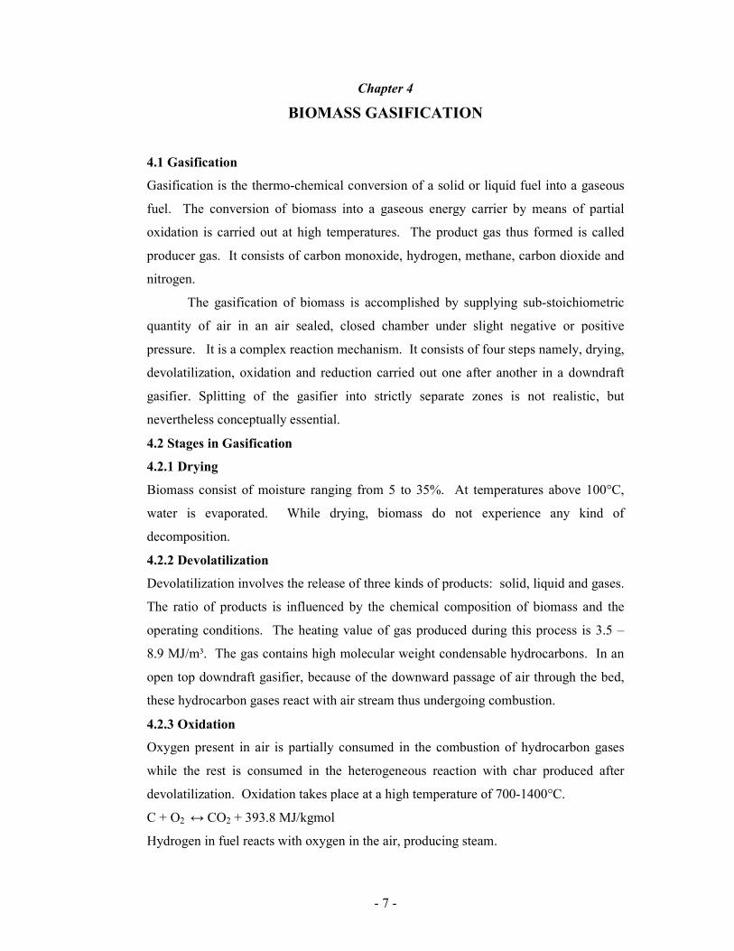
4.1 Gasification
Gasification is the thermo-chemical conversion of a solid or liquid fuel into a gaseous
fuel. The conversion of biomass into a gaseous energy carrier by means of partial
oxidation is carried out at high temperatures. The product gas thus formed is called
producer gas. It consists of carbon monoxide, hydrogen, methane, carbon dioxide and
nitrogen.
The gasification of biomass is accomplished by supplying sub-stoichiometric
quantity of air in an air sealed, closed chamber under slight negative or positive
pressure. It is a complex reaction mechanism. It consists of four steps namely, drying,
devolatilization, oxidation and reduction carried out one after another in a downdraft
gasifier. Splitting of the gasifier into strictly separate zones is not realistic, but
nevertheless conceptually essential.
4.2 Stages in Gasification
4.2.1 Drying
Biomass consist of moisture ranging from 5 to 35%. At temperatures above 100°C,
water is evaporated. While drying, biomass do not experience any kind of
decomposition.
4.2.2 Devolatilization
Devolatilization involves the release of three kinds of products: solid, liquid and gases.
The ratio of products is influenced by the chemical composition of biomass and the
operating conditions. The heating value of gas produced during this process is 3.5 –
8.9 MJ/m³. The gas contains high molecular weight condensable hydrocarbons. In an
open top downdraft gasifier, because of the downward passage of air through the bed,
these hydrocarbon gases react with air stream thus undergoing combustion.
4.2.3 Oxidation
Oxygen present in air is partially consumed in the combustion of hydrocarbon gases
while the rest is consumed in the heterogeneous reaction with char produced after
devolatilization. Oxidation takes place at a high temperature of 700-1400°C.
C + O2 ↔ CO2 + 393.8 MJ/kgmol
Hydrogen in fuel reacts with oxygen in the air, producing steam.

- 8 -
H2 + ½ O2 ↔ H2O + 239 MJ/kgmol
4.2.4 Reduction
In the reduction zone, a number of high temperature chemical readtions take place in
the absence of oxygen. The principal reactions that take place in reduction zone are
mentioned below:
Boudouard reaction: CO2 + C ↔ 2CO – 172.6 MJ/kgmol
Water- gas reaction: C + H2O ↔ CO + H2 – 131.4 MJ/kgmol
Water shift reaction: CO + H2O ↔ CO2 + H2 + 41.2 MJ/kgmol
Methane production reaction: C + 2H2↔ CH4 + 75 MJ/kgmol
Main reactions show that heat is required during the reduction process. Hence, the
temperature of gas goes down during this stage. If complete gasification takes place,
no carbon is left over; only ash is formed. The schematic of a downdraft gasifier is
shown in fig. 4.1.
Biomass + Air
Producer gas + Ash
Drying
Devolatilization
Oxidation
Reduction
Fig 4.1 Sequence of reactions in downdraft gasifier
4.3 Gasifier
Gasifier is a chemical reactor where various complex physical changes and chemical
reactions take place. Any variety of biomass like wood, agricultural wastes, roots of

- 9 -
various crops, maize cobs, etc. can be gasified in the gasifier. Biomass gets dried,
devolatilized, oxidized and reduced, as it flows through the gasifier. The exit producer
gas has a heating value of about 4000-5500 kJ/m3.
4.4 Types of Gasifiers
The gasifiers are classified in many ways. One type of classification is based on the
gas flow direction in the gasifier. Accordingly the gasifiers are classified as:
� Updraft gasifier
� Downdraft gasifier
� Twin-fire gasifier
� Cross draft gasifier
� Other types of gasifiers
4.4.1 Updraft gasifier
Air is introduced at the bottom and flows upwards against the fuel movement. An
updraft gasifier otherwise called as counter-current gasifier (fig. 4.2) has clearly
defined zones for partial combustion, reduction, devolatilization / pyrolysis and drying.
The producer gas is drawn at the top of the gasifier. The updraft gasifier achieves
higher efficiency, since the hot producer gas passes upwards through raw biomass bed,
thus preheating it before leaving the gasifier. The sensible heat of gas is used to
preheat and dry the fuel. The disadvantages of updraft gas producer are excessive
amount of tar in raw gas and poor loading capability. Hence it is not suitable for
running internal combustion engines.
Fig 4.2 Updraft gasifier

- 10 -
4.4.2 Downdraft gasifier
In the updraft gasifier, producer gas leaves the gasifier with high tar content which may
seriously affect the operation of internal combustion engines. This problem is
minimized in downdraft gasifier also called as co-current gasifier (fig. 4.3). In this
type, air is introduced at a higher level; flows downwards through the biomass bed and
producer gas is drawn out at the bottom. A lower efficiency and difficulties in handling
higher moisture content and ash content biomass are common problems in small
downdraft gasifiers. The time needed to ignite and bring the plant to working condition
generating good quality gas is shorter than that required for updraft gasifier. This
gasifier is preferred to updraft gasifier for running internal combustion engines.
Fig 4.3 Downdraft gasifier
4.4.3 Twin-fire gasifier
The advantages of co-current and counter-current gasifiers are combined in twin-fire
gasifier (fig. 4.4). It consists of two well defined reaction zones. Drying, low-
temperature carbonization and cracking of gases occur in the upper zone, while
permanent gasification of charcoal takes place in the lower zone. The gas temperature
lies between 460 to 520 ºC. Twin-fire gasifier produces fairly clean gas.

- 11 -
Fig 4.4 Twin-fire gasifier
4.4.4 Cross draft gasifier
Although cross draft gas producers have certain advantages over updraft and downdraft
gasifiers, they are not ideal. The disadvantages such as high exit gas temperature, poor
CO2 reduction and high gas velocity are the consequences of the design. Unlike
downdraft and updraft gasifiers, the ash bin, fire and reduction zones in cross draft
gasifiers are separate. These design characteristics limit the type of fuel usage
restricted to only low ash fuels such as wood, charcoal and coke (fig. 4.5). The load
following ability of cross draft gasifier is quite good due to concentrated zones which
operate at temperatures up to 1200ºC. Start up time (5 - 10 minutes) is much faster
than that of downdraft and updraft units. The relatively higher temperature in cross
draft gas producer has an obvious effect on exit gas composition such as high carbon
monoxide, and low hydrogen and methane content when dry fuel such as charcoal is
used. Cross draft gasifier operates well on dry air blast and dry fuel.

- 12 -
Fig 4.5 Cross draft gasifier
4.4.5 Other types of gasifiers
Although updraft, downdraft or cross draft gas producers have been the most
commonly built types, there is a wide variety of gasifiers which do not really fit into
any of these categories and are classified as other gas producers. Some units are built
to combine the advantages of cross draft with downdraft or updraft gas producers.
4.5 Producer gas and its constituents
Producer gas is a mixture of combustible and non-combustible gases. The heating
value of producer gas varies from 4.5 to 6 MJ/m³ depending upon the proportion of its
constituents. When atmospheric air is used as gasification agent, the producer gas
consists of mainly carbon monoxide, hydrogen, carbon dioxide and nitrogen. The
general composition of producer gas obtained by wood gasification is given in table 4.1
on volumetric basis.
Table 4.1 General composition of producer gas
Carbon monoxide 18-22 %
Hydrogen 13-19 %
Methane 1-5 %
Heavier hydrocarbons 0.2-0.4 %
Carbon dioxide 9-12 %
Nitrogen 45-55 %
Water vapour 4 %

- 13 -
Carbon monoxide is produced from the reduction of carbon dioxide and its quantity
varies from 18 to 22 % on volume basis. Although carbon monoxide possesses higher
octane number of 106, its burning velocity is low. As it is toxic in nature, operator
needs to be careful while handling the gas.
Hydrogen is also a product of reduction process in the gasifier. Hydrogen
possesses an octane number of 60-66 and it increases the burning velocity of producer
gas. Methane and hydrogen are responsible for higher heating value of producer gas.
Carbon dioxide and nitrogen are non-combustible gases present in the producer gas.
Higher percentage of carbon dioxide indicates incomplete reduction. The presence of
water vapour in producer gas is due to the moisture content in air introduced during
oxidation, the injection of steam in gasifier or the moisture content of biomass.

14
Chapter 5
DEVELOPMENT OF GASIFICATION SYSTEM
5.1 Gasification system
The complete gasification system for electric power generation consists of
(i) biomass gasifier, (ii) a number of equipments for gas cooling and cleaning and (iii)
internal combustion engine + electrical generator. Refer fig. 5.1. The gas cooling and
cleaning are basically unit operations which are carried out in different types of devices
namely cyclone separator, dust filter, gas cooler, etc. The flow of producer gas through
the system is caused by engine suction augmented by a blower. The project
Fig: 5.1 Schematic of biomass gasification system
was initially contemplated to include all these essential elements in the gasification
system. But with the available fund, only the most essential components of the
gasification system have been fabricated and tested so far. It is shown in fig.5.2.
Fig. 5.2 Experimental gasification system

15
5.2 Downdraft gasifier for wood and briquettes
Most of the biomass gasification plants have packed bed type of gasifiers consuming
wood pieces or briquettes. With this background information, a versatile downdraft
biomass gasifier of feeding rate 4-6 kg/h was designed and fabricated. It was
developed in such a way that it can generate producer gas sufficient to drive a 5 h.p
engine.
The experimental system consists of blower, gasifier, cyclone separator, dust
filter and a flare pipe. The motorized blower supplies air to the gasifier. The gasifier is
a packed bed reactor of variable configuration type i.e., it can be used as downdraft,
updraft, throat type or throat less type gasifier. It can be operated by blowing air from
the air blower or by sucking air through the gasifier by means of the blower or an i.c.
engine. Depending upon the requirements, any particular configuration can be chosen
and used for any type of biomass to conduct the experiment. The air supply from the
motorized blower is regulated by a valve. The air flow adjustment is important for
uninterrupted and successful operation of gasifier. The air flow rate is measured by an
orifice meter made of stainless steel. Air enters the gasifier through an air inlet pipe at
the top. The biomass is fed through a feeding port, which is also provided at the top of
gasifier. The biomass feeding port is kept closed during operation of gasifier and
opened only during feeding. The gasifier is a cylindrical shell with provisions for
pressure and temperature measurements. Tappings are provided along the cylindrical
shell of the gasifier at regular intervals. The gasifier is lined inside with refractory
cement to withstand high temperature. The ash accumulated in the ash chamber due to
continuous operation of the gasifier is removed through an ash port. Refer fig. 5.3.
The producer gas exiting the gasifier is passed to a cyclone separator to remove
larger dust particles. Then it is sent to a dust filter for hot gas cleaning. In this filter,
the gas passes through filter elements fabricated of SS sieve (No. 100). There is also a
provision to flare the gas directly after the gasifier without passing through any
downstream equipment. A torch is used initially to ignite the producer gas emanating
from the flare pipe.

16
Fig. 5.3 Gasifier for wood and briquettes
5.3 Downdraft gasifier for loose bioresidues
When loose biomass were used in the gasifier originally developed for wood and
briquettes, certain operational problems arose. This is due to the distinct characteristics
of loose biomass vis-à-vis that of wood pieces or briquettes. Firstly, because of the
fluffiness of loose bioresidues, it was difficult to be fed through the hopper of the
gasifier. No such difficulty was faced in the case of wood pieces. Secondly, the air
supply was not uniform in the gasifier. Gasification of loose bioresidues was done in
the gasifier after doing certain modifications and improvements in its design. They are
explained in the following sections.
5.3.1. Biomass feeding attachment
The feeding attachment consists of a hopper and two open/close type lids. This
provision ensures smooth feeding of the loose biomass into the reactor. The top and
bottom lids never open simultaneously. Refer fig. 5.4. Initially loose biomass is fed
into the hopper by opening the top lid. Then the bottom lid is opened using shutter and
lever mechanism. This arrangement helps in feeding the fuel without stopping the
blower and it also ensures continuous running of the gasifier. Because of this lock
hopper type arrangement, escapement of gases through the feed port during feeding of
biomass was also avoided. The feeding area has been increased by about 60 % which
facilitates free flowing of loose biomass into the gasifier.

17
Fig. 5.4 Biomass feeding attachment
5.3.2 Central air supply pipe
In the initial design originally developed for wood pieces, air was supplied from a
blower directly into the gasifier through the top cover. This resulted in improper
distribution of air inside the gasifier and hence reaction zones were not stratified. To
ensure proper air entry into the gasifier and its uniform distribution inside the gasifier,
an improved design of air supply pipe was incorporated in the gasifier. In the improved
design, an annular distributor pipe is used to supply air into the gasifier.
5.3.3. Bed agitating rod
An agitating rod passing through the centre of the reactor maintains the top surface of
biomass bed even. This provision aids in achieving better stratification of reaction
zones.
5.3.4 Sight glass
A provision has been made on the top cover of the reactor to fit a sight glass. The sight
glass is used to see the inside of the reactor during operation and helps to maintain the
biomass bed level as per the requirement.

18
Chapter 6
EXPERIMENTS
6.1 Determination of some physical properties
First, some properties of certain loose biomass were determined. Bulk density,
apparent particle density and voidage are the physical properties which were
determined for certain biomass in the lab by following brief procedures.
6.1.1 Bulk density (ρ)
It is the mass of biomass particles per unit volume of the biomass particles including
voids between the particles and pores within the particles. Bulk density is not an
intrinsic property of a loose biomass; it can change depending on how the biomass is
handled. It is a measure of the "fluffiness” of loose biomass in its natural form.
It was determined by taking biomass in a 1000 ml measuring jar and placing it
on a digital weighing balance (1 g accuracy) and measuring the total weight as M1.
The weight of empty jar is then measured as M2.
Bulk density ρ = (M1-M2)/V
where M1 = total weight of (biomass + jar)
M2 = weight of jar
V = volume of jar (1000 ml)
6.1.2 Apparent particle density (ρs)
It is the mass of a biomass particle divided by its volume including pores which are
inherently present in it. A single biomass particle was weighed (M) in a digital
weighing balance of 0.001 g accuracy. Its volume (V) was then measured by a suitable
method.
Apparent particle density ρs = M/V
6.1.3 Voidage (e)
It is the fraction of volume of the vessel not occupied by solid biomass particles.
6.2 Determination of operational parameters
Some of the operational parameters of the gasifier like superficial air velocity,
residence time of air and surface area of bed per unit volume of the gasifier were
determined for different air flow rates for each biomass. Carman-Kozeny equation was
used to determine the surface area of the bed per unit volume for each biomass.

19
6.3 Tests for pressure drop measurement
Tests for pressure drop measurement along the depth of biomass bed were carried out
under forced, downdraft mode with throat, in the unfired condition of gasifier. Refer
fig.6.1. The bottom opening of the diverging portion below the throat of gasifier was
closed with a wire mesh. A known quantity of wood pieces was charged into the
gasifier up to the level of topmost pressure tapping. The top surface of biomass bed is
taken as the reference for describing the position of pressure measurement.
Manometers were connected to all the pressure tappings. A manometer was also
connected across the orifice meter to measure air flow rate. The blower was started and
delivery valve was kept fully open. Under this condition, the static pressure readings
along the depth of biomass bed and orificemeter reading were noted. The air flow was
then reduced in equal steps by regulating the blower valve. For each valve opening, all
the static pressure readings along the depth of biomass bed and orificemeter reading
were noted. The same experimental procedure was followed for different biomass like
wood shavings, saw dust, coir pith, groundnut shells and charcoal.
Fig 6.1 Pressure drop measurement
6.4 Gasification tests
During gasification, generally there will be temperature stratification inside the gasifier
at different depths. The actual temperature field was sensed by thermocouples inserted
through the temperature tappings. Trials were conducted using wood pieces and
groundnut shells separately. In each case, the gasifier was initially charged with 1 kg
charcoal and ignited. The centrifugal blower supplied air for gasification and its flow

20
rate was measured by orifice meter. The gasifier was operated in forced, downdraft
mode. Refer fig.6.2. Once sufficient temperature was attained, biomass was fed in
batches of 0.5 - 1 kg at a rate such that a desired bed height was reached. After
reaching the desired bed height, the biomass feed rate was maintained at a value such
that the bed height remained constant atleast for an hour during gasification trial.
Biomass feed quantity was measured by a weighing balance of 1 g resolution.
Temperature distribution along the depth of biomass bed was measured using ‘K’ type
thermocouples inserted through eight tappings along the gasifier axis. The producer
gas was flared at the opening of outlet pipe.
To finish the experiment, biomass feeding was stopped and air supply was
continued for some more time. Because of biomass consumption due to gasification,
its level gradually decreased inside the reactor. Once the level reached the initial level
of charcoal taken, air supply was cut off and the reactions were stopped. The quantity
of final residue was weighed.
Fig. 6.2 Gasifier in operation

21
Chapter 7
RESULTS AND DISCUSSION
7.1 Measured values of some physical properties
The measured values of the some physical properties are shown in Table 7.1 for certain
biomass.
Table 7.1 Some physical properties of certain biomass
Sl.
No.
Biomass Apparent Particle
Density
ρs (kg/m3)
Bulk Density
ρb
(kg/m3)
Fractional
Voidage
e
1 Cashew nut shell 1152.5 295 0.68
2 Ground nut shell 366.66 89 0.76
3 Cashew nut shell char 368.96 123 0.74
4 Ground nut shell char 185.7 57 0.84
5 Charcoal 336 188 0.59
It is evident that charification reduces apparent particle density, bulk density but
increases voidage of biomass.
7.2 Operational parameters
The operational parameters of the gasifier like superficial air velocity, residence time of
air and surface area of bed per unit volume of the gasifier were determined for different
air flow rates for each biomass. Table 7.2 gives the results for groundnut shells
(biomass) and charcoal (biochar) only. These are the values obtained when gasification
air passed through the packed bed biomass gasifier.
Table 7.2 Superficial air velocity, Residence time and Surface area of bed per unit
volume for certain biomass
Sl.
No.
Biofuel Superficial air
velocity
(m/s)
Residence
Time
(s)
Surface of bed per
unit volume
(m2/m
3)
1 Groundnut
shells
3.56
3563
2 Charcoal
0.115
3335
The results indicate that dissimilar physical properties of biomass tend to control the
chemical reactions differently.

22
7.3 Pressure drop in biomass beds
7.3.1 Wood pieces
The pressure drop along the depth of a bed of wood pieces is shown in fig. 7.1, for ten
different air flow rates. The maximum possible air flow rate in the case of wood pieces
is 0.0114 m3/s. It is evident that the total pressure drop across the bed depth is only 4
mm of water column. Due to this, the air blower power requirement for wood pieces
gasification will be the minimum.
Distance Vs Pressure head (wood pieces)
0
10
20
30
40
50
60
70
80
0 0.2 0.4 0.6 0.8
Pressure head (cm of WG)
Distance fro
m w
ire m
esh
(cm
)
0.0114 m3/s
0.0109 m3/s
0.0102 m3/s
0.0096 m3/s
0.0089 m3/s
0.0081 m3/s
0.0072 m3/s
0.0062 m3/s
0.0051 m3/s
0.0037 m3/s
Distance Vs Pressure head (wood shavings)
0
10
20
30
40
50
60
70
80
0 1 2 3 4
Pressure head (cm of WG)
Distance fro
m w
ire m
esh (cm) 0.0096 m3/s
0.0089 m3/s
0.0081 m3/s
0.0072 m3/s
0.0062 m3/s
0.0051 m3/s
0.0037 m3/s
Fig. 7.1 Pressure drop for wood pieces Fig. 7.2 Pressure drop for wood shavings
7.3.2 Wood shavings
The pressure drop along the depth of a bed of wood shavings is shown in fig. 7.2, for
seven different air flow rates. The maximum possible air flow rate in the case of wood
shavings is 0.0096 m3/s. It is clear that the total pressure drop across the bed depth is
about 8 mm of water column. Due to this, the air blower power requirement will be
greater than that for wood pieces gasification.
7.3.3 Saw dust
The pressure drop along the depth of a bed of saw dust is shown in fig. 7.3, for only
one air flow rate which is the maximum possible i.e., 0.0024 m3/s. As the maximum
possible air flow rate itself was very less, trials for still lower air flow rates could not be
conducted. From fig. 7.3, it can be seen that the total pressure drop across saw dust bed
is about 60 mm of water column which is the largest among all biomass. Due to this,
the air blower power requirement for saw dust gasification will be the maximum.

23
Distance Vs Pressure head (saw dust)
0
10
20
30
40
50
60
70
80
0 2 4 6 8 10 12
Pressure head (cm of WG)
Distance from wire mesh (cm)
Distance Vs Pressure head (coir pith)
0
10
20
30
40
50
60
70
80
0 2 4 6 8
Pressure head (cm of WG)
Distance from w
ire m
esh (cm) 0.0075 m3/s
0.0063 m3/s
0.0052 m3/s
0.0038 m3/s
Fig. 7.3 Pressure drop for saw dust Fig. 7.4 Pressure drop for coir pith
7.3.4 Coir pith
The pressure drop along the depth of a bed of coir pith is shown in fig.7.4, for four
different air flow rates. The maximum possible air flow rate is 0.0075 m3/s. The total
pressure drop across the bed depth is about 20 mm of water column. Due to this, the
air blower power requirement will be lesser than that for saw dust gasification.
7.3.5 Groundnut shells
The pressure drop along the depth of a bed of groundnut shells is shown in fig. 7.5, for
eight different air flow rates. The maximum possible air flow rate in the case of
groundnut shells is 0.0102 m3/s. It has been found that the total pressure drop across
the bed depth is about 6 mm of water column. Due to this, the air blower power
requirement will be considerably lesser than that for saw dust, coir pith and wood
shavings gasification.
7.3.6 Charcoal
The pressure drop along the depth of a bed of charcoal is shown in fig. 7.6, for nine
different air flow rates. The maximum possible air flow rate is 0.0108 m3/s. The total
pressure drop across the bed depth is about 3 mm of water column. Due to this, the air
blower power requirement will be lesser than that for wood gasification.

24
Distance Vs Pressure head (groundnutshell)
0
10
20
30
40
50
60
70
80
0 0.5 1 1.5 2
Pressure head (cm of WG)
Distance from w
ire m
esh (cm) 0.0102 m3/s
0.0096 m3/s
0.0089 m3/s
0.0081 m3/s
0.0072 m3/s
0.0062 m3/s
0.0051 m3/s
0.0036 m3/s
Distance Vs Pressure head (charcoal)
0
10
20
30
40
50
60
70
80
0 0.5 1 1.5 2
Pressure head (cm of WG)
Distance from w
ire m
esh (cm) 0.0108 m3/s
0.0102 m3/s
0.0096 m3/s
0.0089 m3/s
0.0081 m3/s
0.0072 m3/s
0.0063 m3/s
0.0051 m3/s
0.0036 m3/s
Fig.7.5 Pressure drop for groundnut shells Fig. 7.6 Pressure drop for charcoal
The inlet static head (in cm of WC) required to cause different air flow rates in
forced draft mode of operation of gasifier for six different biomass are shown in fig.
7.7.
Inlet static head Vs Air Flow rate
0
2
4
6
8
10
12
0 0.005 0.01 0.015
Air Flow rate (m3/s)
Inlet static head (cm)
wood pieces
coir pith
sawdust
wood
shavingsgroundnut
shellscharcoal
Fig. 7.7 Plot of Inlet static head vs Air flow rate
7.4 Temperature distribution during gasification
The results of gasification of two types of biomass namely wood pieces and groundnut
shell are presented in fig. 7.8 and fig. 7.9 respectively. The temperature distributions
along the depth of wood pieces and groundnut shell beds are shown in the figures,
besides the fuel feeding rate and the bed height, for entire test duration.

25
Temperature vs Time
0
250
500
750
1000
1250
0 100 200 300
Time (min)
Tem
pera
ture
(C) T1
T2
T3
T4
Temperature vs Time
0
100
200
300
400
500
600
700
0 50 100 150
Time (min)
Tem
pera
ture
(C) T2
T3
T4
Feed vs Time
0
5
10
15
0 100 200 300
Time (min)
Feed (kg)
Cumulative Instantaneous
Feed vs Time
0
1
2
3
4
5
6
0 50 100 150Time (min)
Feed (kg)
instantaneous cumulative
Bed height vs Time
0
20
40
60
80
100
0 100 200 300
Time (min)
Bed h
eig
ht (c
m)
Bed height vs Time
0
10
20
30
40
50
0 50 100 150
Time (min)
Bed h
eig
ht (c
m)
Fig.7.8 Temperature distribution, fuel Fig.7.9 Temperature distribution, fuel
feeding and bed height change feeding and bed height change
during gasification of wood pieces during gasification of g.n. shells
During steady state operation of the gasifier, the heat transfer from oxidation zone to
upper packed column of biomass caused drying and devolatilization of raw biomass,
which was fed at a constant rate. The rate of downward movement of biomass was
equal to the rate of upward progress of oxidation zone. But towards the end of
experiment, when biomass feeding was stopped, the biomass level decreased gradually
inside the gasifier as gasification was allowed to continue by supplying air. The drying

26
and devolatilization zones shrunk while the oxidation zone extended upwards. As a
result, the top layer of biomass bed underwent high temperature oxidation. Due to this,
the radiation heat loss from red-hot biomass bed to the reactor inner surfaces increased.
In the final stage of each biomass gasification trial, as the contents of gasifier became
char, char gasification took place. The quality of producer gas was better towards the
end of experiment, which could be observed for both wood pieces and groundnut shell
gasification.
Channeling and bridging problems were experienced during gasification of
groundnut shells in packed bed. By agitating the bed, these problems were overcome.
Clinkers were also formed in the case of groundnut shell gasification, whereas no such
phenomenon occurred in wood gasification. This was due to lower ash fusion
temperature of groundnut shell ash. This can be overcome if bed temperature is
maintained lower than ash fusion temperature. One of the methods of achieving this, is
to decrease the char residence time.

27
Chapter 8
CONCLUSIONS
8.1 Properties of loose biomass
From the values of various properties determined for certain loose biomass, the
following observations are made:
• Loose biomass have lesser bulk density and higher bed voidage.
• Surface area of bed per unit volume of bed is higher for loose biomass.
• Flow of loose biomass inside the gasifier is hampered by their inherent
characteristics.
• Charification decreases bulk density and apparent particle density but increases
fractional voidage.
8.2 Pressure drop in gasifiers
From the experiments conducted to determine pressure drop in biomass beds, the
following points are concluded:
• The pressure drop for air flow is highest in the case of saw dust bed and is least
for the bed of charcoal.
• For the same air flow rate through the bed, higher inlet air pressure is necessary
in the case of saw dust.
• The pressure drop depends very much on the physical structure of biomass
particle. The pressure drop is inversely proportional to the particle diameter.
• The pressure drop is directly proportional to the air flow rate for all biomass.
• For the same pressure drop and air flow rate, bed height of wood pieces can be
more than that of loose bioresidues.
• Equations can be used to determine pressure distribution along the depth of
biomass bed.
8.3 Gasification tests
From the gasification tests, the following points are concluded:
• Gasification of wood pieces is easier and particulate content in producer gas is
also lesser.
• Gasification of groundnut shells is also good but particulate content in producer
gas is more. Because of this, more elaborate cleaning of producer gas becomes
essential before supplying it to the engine.
28
• When the bed height of groundnut shells is maintained low, producer gas
generation is better but frequency of fuel feeding increases.
• By agitating the bed of groundnut shells, the problems of choking and bridging
can be overcome and producer gas generation will be better.
• Dissimilar physical properties of biomass control the chemical reactions
differently.
It is possible to use non-woody loose bioresidues in the small scale packed bed type of
gasifiers with only minor modifications in the design and operation. In the larger
commercial packed bed type of gasifiers, loose bioresidues can be used if the bed
height is maintained at a minimum level and if the bed is agitated at regular interval of
time.

29
RELATED LITERATURES
1. E. M. H. Khater, N. N. El-Ibiary, I. A. Khattab and M. A. Hamad, “Gasification of
rice hulls”, Biomass and Bioenergy, Vol. 3, No. 5, pp. 329-333, 1992.
2. Valentino M. Tiangco, Bryan M. Jenkins and John R. Goss, “Optimum specific
gasification rate for static bed rice hull gasifiers”, Biomass and Bioenergy, Vol.
11, No. 1, pp. 51-62, 1996.
3. Anil Kr Jain and John R. Goss, “Determination of reactor scaling factors for
throatless rice husk gasifier”, Biomass and Bioenergy, 18 (2000), pp. 249-256.
4. M. Dogru, C. R. Howarth, G. Akay, B. Keskinler, A. A. Malik, “Gasification of
hazelnut shells in a downdraft gasifier”, Energy, 27 (2002), pp. 415-427.
5. Jae Ik Na, So Jin Park, Yong Koo Kim, Jae Goo Lee, Jae Ho Kim, “Characteristics
of oxygen-blown gasification for combustible waste in a fixed-bed gasifier”,
Applied Energy, 75 (2003), pp. 275-285.
6. R. N. Singh, U. Jena, J. B. Patel, A. M. Sharma, “Feasibility study of cashew nut
shells as an open core gasifier feedstock”, Renewable Energy, 2005, pp. 1-7.
7. B.N. Baliga, S.Dasappa, V.Shrinivasa and H.S.Mukunda, “Gasifier based power
generation: Technology and Economics”, Sadhana, Vol. 18, Part I, pp 57-75, 1993.
8. P. Hasler, Th. Nussbaumer “Gas cleaning for IC engine application from fixed
biomass gasification”, Biomass and Bioenergy, Vol.16, pp. 385 -395, 1999.
9. A.Ramachandra, “Performance studies on wood gas run IC engines”, Proceedings
of the National Meet at Mysore, Recent advances in Biomass Gasification and
Combustion, 1993.
10. “Biomass Thermochemical Characterization” Indian Institute of Technology, New
Delhi, 1997.