polythiophene and oligothiophene systems modified · pdf filepolythiophene and oligothiophene...
TRANSCRIPT

1749
Polythiophene and oligothiophene systems modified by TTFelectroactive units for organic electronicsAlexander L. Kanibolotsky*1,2, Neil J. Findlay1 and Peter J. Skabara*1
Review Open Access
Address:1WestCHEM, Department of Pure and Applied Chemistry, Universityof Strathclyde, 295 Cathedral Street, Glasgow, G1 1XL, UnitedKingdom and 2Institute of Physical-Organic Chemistry and CoalChemistry, 02160 Kyiv, Ukraine
Email:Alexander L. Kanibolotsky* - [email protected];Peter J. Skabara* - [email protected]
* Corresponding author
Keywords:donor; oligothiophene; organic electronics; polythiophene;semiconductor; tetrathiafulvalene
Beilstein J. Org. Chem. 2015, 11, 1749–1766.doi:10.3762/bjoc.11.191
Received: 23 May 2015Accepted: 30 August 2015Published: 28 September 2015
This article is part of the Thematic Series "Tetrathiafulvalene chemistry".
Associate Editor: S. C. Zimmerman
© 2015 Kanibolotsky et al; licensee Beilstein-Institut.License and terms: see end of document.
AbstractThe aim of this review is to give an update on current progress in the synthesis, properties and applications of thiophene-based
conjugated systems bearing tetrathiafulvalene (TTF) units. We focus mostly on the synthesis of poly- and oligothiophenes with
TTF moieties fused to the thiophene units of the conjugated backbone either directly or via a dithiin ring. The electrochemical
behaviour of these materials and structure–property relationships are discussed. The study is directed towards the development of a
new type of organic semiconductors based on these hybrid materials for application in organic field effect transistors and solar cells.
1749
IntroductionSulfur-rich π-functional systems are important building blocks
in materials chemistry. Among them, tetrathiafulvalene (TTF)
electron donor and polythiophene (PT) conjugated systems are
highly popular classes of organic compounds which have shown
fascinating conducting and electronic properties. The advan-
tages of PT-based materials are their synthetic versatility, excel-
lent film-forming properties and potential to increase the dimen-
sionality of charge carrier transport [1] by involving π–π
stacking interactions. Varying the substituents of the conju-
gated backbone allows control over the polymer’s effective
conjugation length and electronic properties, whilst also influ-
encing the extent of inter-chain interactions. Two of the most
studied polythiophene materials for organic electronics are
regioregular poly(3-hexylthiophene) (P3HT) [2,3] and poly(3,4-
ethylenedioxythiophene) (PEDOT) [4], which is highly conduc-
tive in its doped state. P3HT has become a benchmark polymer
semiconductor for both bulk hetero-junction solar cells
(BHJSCs) [5] and organic field effect transistors (OFETs) [6,7],
whereas the PEDOT:poly(styrene sulfonate) salt (PEDOT:PSS)
was originally investigated for antistatic applications but is now
commercially available for its use as a hole-injecting/collecting
material for organic light emitting diodes (OLEDs) and
BHJSCs. So far, various electroactive units have been anchored
aside the polythiophene backbone, including ferrocene [8], por-

Beilstein J. Org. Chem. 2015, 11, 1749–1766.
1750
Scheme 1: The synthesis of PT based conjugated systems with the TTF unit incorporated within the polymer backbone.
phyrin [9], 2-carboxyanthraquinone [10], 1,3-dithiole-2-
ylidenefluorene [11,12], dithiinoquinoxaline [13,14] and
fullerene C60 [15,16]. The incorporation of acceptor units into a
conjugated network is a standard way to narrow the HOMO/
LUMO band gap and examples of such units include dioxo-
pyrrolopyrrole (DPP) [17-19], benzodifuranone [20] and boron-
dipyrromethene (BODIPY) [21,22].
As a different class of electroactive materials, TTF derivatives
are well-known as reversible redox systems with low potentials
of oxidation to cation radical and dication species. The high
level of stability observed for the oxidised TTF π-electron
system arises from the aromatic nature of the oxidised 1,3-
dithiolium rings and this has triggered tremendous efforts
directed toward the synthesis of compounds with TTF donor
units and subsequent investigation of their properties. Since the
first discovery of the semiconducting properties of TTF and its
cation radical [23], and the metallic behaviour of the TTF-
TCNQ charge transfer complex [24], great attention was
focused on the preparation of TTF mixed valance state ma-
terials, which showed superconducting properties [25]. Fusing
the TTF unit with dithiin rings in bis(ethylenedithio)tetrathiaful-
valene (BEDT-TTF) led to the extension of 1D π–π stacking
intermolecular interactions in a donor sheet of a mixed valance
state system to 2D with a significant contribution from S···S
non-covalent interactions [26]. This gave a record transition
temperature among TTF mixed valence ambient pressure super-
conductors in the salt κ-(BEDT-TTF)2Cu[N(CN)2]Br [27]. In
an attempt to create macromolecular compounds with multi-
electron redox activity and to further increase the dimension-
ality of their intermolecular interactions in the solid phase, the
TTF units were incorporated into dendritic structures [28-32].
The extraordinary propensity of TTF and its doped species to
aggregate was the reason for using this unit in the design of
gelators [33,34].
Combining the exceptional donor strength of TTF and excel-
lent film-forming properties of a conjugated polymer (CP)
opens up the possibility to create promising materials with
interesting redox behaviour. So far the TTF unit has been used
for redox modification of various CP systems [35] including
incorporation within the conjugated backbone [36,37], as a
pendant unit [38-40] and direct fusion to the π-conjugated
system of the polymer [41,42]. Incorporation of a TTF unit into
a PT architecture allows the creation of interesting hybrid redox
systems with a wide range of electro-activities. The goal of this
review is to provide an update on the synthesis of TTF-PT
hybrid conjugated systems, their properties and their applica-
tion to organic electronics. Both electrodeposition and chem-
ical polymerisation will be considered as methods of producing
the PT conjugated backbone. In some cases poly(ethynylene/
vinylene) homologues will be considered for comparison. Addi-
tionally, monodispersed tetrathiafulvalene-oligothiophene
(TTF-OT) conjugated systems will be discussed as their
well-defined structures provide a stronger insight into
structure–property relationships.
ReviewPT conjugated systems with TTF units withinthe polymer backbone or as pendant unitsThe most straightforward way to modify PT conjugated systems
is to incorporate the TTF unit into the polymer backbone or
attach it as a pendant unit, as only minor modifications to the
synthesis of the TTF/thiophene monomer are required. Both
chemical [43] and electrochemical polymerisation [44] have
been used to incorporate a TTF moiety within the polythio-
phene backbone. Yamamoto coupling of diiodo monomers 1a
and 1b provided polymer 1c, albeit with a modest molecular
weight (Mw = 5800 Da) compared to that of the polymer 1d,
which was obtained by Sonogashira coupling of 1b with 1e and
exhibited a partial solubility in THF with Mw = 610000 Da
(THF soluble fraction) [43] (Scheme 1).
Polymer properties in the solid state are hugely important for
organic electronics applications, with the electronic properties
of materials being greatly affected by film morphology. The
Beilstein J. Org. Chem. 2015, 11, 1749–1766.
1751
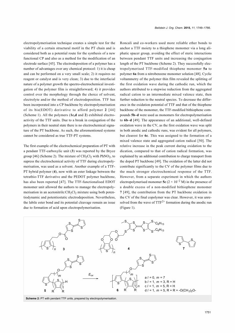
Scheme 2: PT with pendant TTF units, prepared by electropolymerisation.
electropolymerisation technique creates a simple test for the
viability of a certain structural motif in the PT chain and is
considered both as a potential route for the synthesis of a new
functional CP and also as a method for the modification of an
electrode surface [45]. The electrodeposition of a polymer has a
number of advantages over any chemical protocol: 1) it is cheap
and can be performed on a very small scale; 2) it requires no
reagent or catalyst and is very clean; 3) due to the interfacial
nature of a polymer growth the spectro-electrochemical investi-
gation of the polymer film is straightforward; 4) it provides
control over the morphology through the choice of solvent,
electrolyte and/or the method of electrodeposition. TTF has
been incorporated into a CP backbone by electropolymerisation
of its bis(EDOT) derivative to afford polymer 2 [44]
(Scheme 1). All the polymers (1c,d and 2) exhibited electro-
activity of the TTF units. Due to a break in conjugation of the
polymers in their neutral state there is no electrochemical signa-
ture of the PT backbone. As such, the aforementioned systems
cannot be considered as true TTF-PT systems.
The first example of the electrochemical preparation of PT with
a pendant TTF-carboxylic unit (3) was reported by the Bryce
group [46] (Scheme 2). The mixture of CH2Cl2 with PhNO2, to
supress the electrochemical activity of TTF during electropoly-
merisation, was used as a solvent. Another example of a TTF-
PT hybrid polymer (4), now with an ester linkage between the
tetrathio-TTF derivative and the PEDOT polymer backbone,
has also been reported [47]. The TTF-functionalised EDOT
monomer unit allowed the authors to manage the electropoly-
merisation in an acetonitrile:CH2Cl2 mixture using both poten-
tiodynamic and potentiostatic electrodeposition. Nevertheless,
the labile ester bond and its potential cleavage remain an issue
due to formation of acid upon electropolymerisation.
Roncali and co-workers used more reliable ether bonds to
anchor a TTF moiety to a thiophene monomer via a long ali-
phatic spacer group, avoiding the effect of steric interactions
between pendant TTF units and increasing the conjugation
length of the PT backbone (Scheme 2). They successfully elec-
tropolymerised TTF-modified thiophene monomer 5a to
polymer 6a from a nitrobenzene monomer solution [48]. Cyclic
voltammetry of the polymer thin film revealed the splitting of
the first oxidation wave during the cathodic run, which the
authors attributed to a stepwise reduction from the aggregated
radical cation to an intermediate mixed valence state, then
further reduction to the neutral species. To decrease the differ-
ence in the oxidation potential of TTF and that of the thiophene
backbone of the monomer, the TTF-modified bithiophene com-
pounds 5b–d were used as monomers for electropolymerisation
to 6b–d [49]. The appearance of an additional, well-defined
oxidation wave in the CV, as the first oxidation wave was split
in both anodic and cathodic runs, was evident for all polymers,
but clearest for 6c. This was assigned to the formation of a
mixed valence state and aggregated cation radical [50]. The
relative increase in the peak current during oxidation to the
dication, compared to that of cation radical formation, was
explained by an additional contribution to charge transport from
the doped PT backbone [49]. The oxidation of the latter did not
contribute significantly to the CV of the polymer films due to
the much stronger electrochemical response of the TTF.
However, from a separate experiment in which the authors
electropolymerised monomer 5c (2 × 10⁻² M) in the presence of
a double excess of a non-modified bithiophene monomer
7 [49], the contribution from the PT backbone oxidation in
the CV of the final copolymer was clear. However, it was unre-
solved from the wave of TTF2+ formation during the anodic run
(Figure 1).

Beilstein J. Org. Chem. 2015, 11, 1749–1766.
1752
Scheme 3: PT with pendant TTF units prepared by electropolymerisation and post-modification of polymerised PT through iodoalkyl functionality.
Figure 1: Cyclic voltammograms of copolymers electrodeposited fromnitrobenzene solutions of TTF modified monomer 6c and nonsubsti-tuted bithiophenes 7. Left: 2 × 10⁻² M of 6c; middle: 2 × 10⁻² M of 6c +1 × 10⁻² M of 7; right: 2 × 10⁻² M of 6c + 4 × 10⁻² M of 7; ref. SCE,0.1 M (TBA)PF6 in acetonitrile as an electrolyte. Reproduced withpermission from [49]. Copyright 1998 Wiley-VCH.
An alternative way of preparing PT hybrid materials with TTF
pendant groups was to modify the pre-polymerised PT
containing an appropriate functionality with a TTF derivative.
The Roncali group reported electropolymerisation of EDOT
monomers 8a,b bearing a ω-iodo-functionalised aliphatic chain
to polymers 9a,b, which was followed by the heterogeneous
reaction of the polymeric film with TTF thiolates 10a [51] and
10c [52] to produce the polymers 11a–d (Scheme 3). The poly-
mers 11a,c were also prepared by electropolymerisation of the
corresponding TTF functionalised monomers 12a,c [52]. The
electrochemical response from the polymeric film of 11c,
prepared by functionalising prepolymerised PEDOT 9a with
thiolatoTTF 10c, and that prepared by direct electropolymerisa-
tion of 12c turned out to be very similar, confirming that the
heterogeneous derivatisation of 9a with 10c was rapid and
quantitative with no significant effect on the integrity of the
polymer. The crown ether TTF modified polymers 11c,d were
tested for electrochemical recognition of Ba2+ ions. At [Ba2+]
saturation concentration of 4 mM the shifts of the first
CV peak for 11c and 11d films were +60 and +30 mV with a
TTF electrode coverage of 1.4 × 10⁻⁹ and 9 × 10⁻⁹ mol/cm2,
respectively.
A recent example of the chemical preparation of PT with
pendant TTF-units has been reported [53] (Scheme 4) where
direct arylation polymerisation of quaterthiophene 13a and
3-(acetoxymethyl)thiophene (13b), followed by acidic hydrol-
ysis of the ester groups in polymer 13c, provided the polymer
13d with hydroxy groups for further modification by
ω-bromooctyloxymethylTTF 13f . The CV of the final PT-TTF
compound 13e showed mainly the characteristics of the PT
backbone; due to the low content of the TTF unit in the polymer
13e, the two oxidation waves related to formation of TTF cation
radical and dication were not apparent in the CV of the film, but
were discernible in solution state. Pure 13e, and 13e with a
small amount of the parent poly(3,3'''-didodecyl-2,2':5',2'':5'',2'''-
quaterthiophene) (PQT12) (5 or 10 wt %), did not exhibit any
OFET activity due to hole trapping by the TTF unit. This hole
trapping was explained to be the reason for a negative Seebeck
coefficient of the non-doped polymer 13e and was used for
sensing trinitrotoluene (TNT) using the drain-source current-
increase response to TTF-TNT complexation in an OFET fabri-
cated from 13e with 5% of PQT12.
Conjugated OT systems with fused TTF unitsSynthesis of the monomer unitsIncorporation of a TTF unit into a PT architecture via fusion to
the polymer backbone allows the realisation of highly diverse
electroactive conjugated systems with different contributions to
the properties from each of the components. In contrast to poly-
mers where TTF is attached as a pendant unit or incorporated
Beilstein J. Org. Chem. 2015, 11, 1749–1766.
1753
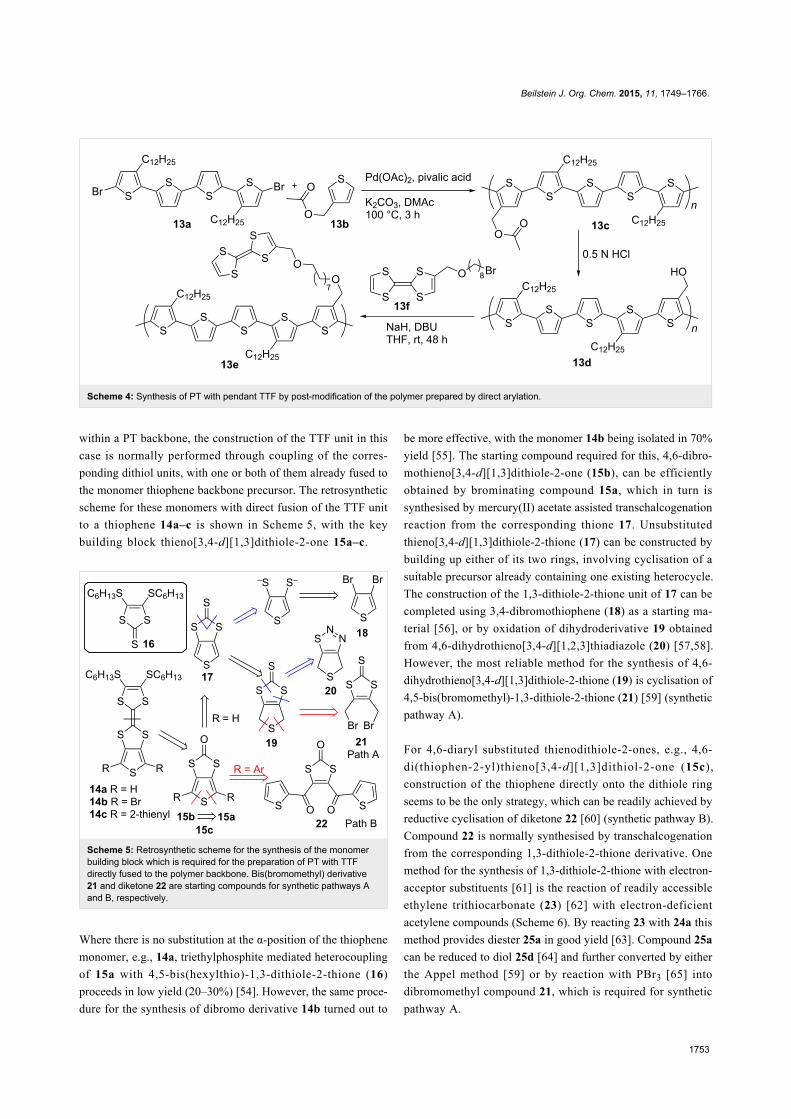
Scheme 4: Synthesis of PT with pendant TTF by post-modification of the polymer prepared by direct arylation.
within a PT backbone, the construction of the TTF unit in this
case is normally performed through coupling of the corres-
ponding dithiol units, with one or both of them already fused to
the monomer thiophene backbone precursor. The retrosynthetic
scheme for these monomers with direct fusion of the TTF unit
to a thiophene 14a–c is shown in Scheme 5, with the key
building block thieno[3,4-d][1,3]dithiole-2-one 15a–c.
Scheme 5: Retrosynthetic scheme for the synthesis of the monomerbuilding block which is required for the preparation of PT with TTFdirectly fused to the polymer backbone. Bis(bromomethyl) derivative21 and diketone 22 are starting compounds for synthetic pathways Aand B, respectively.
Where there is no substitution at the α-position of the thiophene
monomer, e.g., 14a, triethylphosphite mediated heterocoupling
of 15a with 4,5-bis(hexylthio)-1,3-dithiole-2-thione (16)
proceeds in low yield (20–30%) [54]. However, the same proce-
dure for the synthesis of dibromo derivative 14b turned out to
be more effective, with the monomer 14b being isolated in 70%
yield [55]. The starting compound required for this, 4,6-dibro-
mothieno[3,4-d][1,3]dithiole-2-one (15b), can be efficiently
obtained by brominating compound 15a, which in turn is
synthesised by mercury(II) acetate assisted transchalcogenation
reaction from the corresponding thione 17. Unsubstituted
thieno[3,4-d][1,3]dithiole-2-thione (17) can be constructed by
building up either of its two rings, involving cyclisation of a
suitable precursor already containing one existing heterocycle.
The construction of the 1,3-dithiole-2-thione unit of 17 can be
completed using 3,4-dibromothiophene (18) as a starting ma-
terial [56], or by oxidation of dihydroderivative 19 obtained
from 4,6-dihydrothieno[3,4-d][1,2,3]thiadiazole (20) [57,58].
However, the most reliable method for the synthesis of 4,6-
dihydrothieno[3,4-d][1,3]dithiole-2-thione (19) is cyclisation of
4,5-bis(bromomethyl)-1,3-dithiole-2-thione (21) [59] (synthetic
pathway A).
For 4,6-diaryl substituted thienodithiole-2-ones, e.g., 4,6-
di(thiophen-2-yl)thieno[3,4-d][1,3]dithiol-2-one (15c),
construction of the thiophene directly onto the dithiole ring
seems to be the only strategy, which can be readily achieved by
reductive cyclisation of diketone 22 [60] (synthetic pathway B).
Compound 22 is normally synthesised by transchalcogenation
from the corresponding 1,3-dithiole-2-thione derivative. One
method for the synthesis of 1,3-dithiole-2-thione with electron-
acceptor substituents [61] is the reaction of readily accessible
ethylene trithiocarbonate (23) [62] with electron-deficient
acetylene compounds (Scheme 6). By reacting 23 with 24a this
method provides diester 25a in good yield [63]. Compound 25a
can be reduced to diol 25d [64] and further converted by either
the Appel method [59] or by reaction with PBr3 [65] into
dibromomethyl compound 21, which is required for synthetic
pathway A.

Beilstein J. Org. Chem. 2015, 11, 1749–1766.
1754
Scheme 6: Synthesis of bisfunctionalised derivatives of vinylenetrithiocarbonate 21 and 25c required for synthetic pathways A and B,respectively.
Even though the reaction of 23 with acetylene compound 24b
(containing only one electron-withdrawing group) is efficient,
affording 25b with a 60% yield [66], attempts to invoke cyclo-
addition of 23 and 24c in a similar manner led to a poor yield of
25c (8%) [60]. An efficient method for the synthesis of 25c – a
compound required for synthetic pathway B – was found to be
repeated sequential lithiation of vinylene trithiocarbonate (26)
[67] followed by subsequent trapping of the lithium organic
species with thiophenecarboxaldehyde 27 [60]. The diol 25e,
formed as a product of this reaction, is unstable and undergoes
various rearrangments [68,69] in acidic conditions. Hence, it is
preferably oxidised directly to the more stable diketone 25c
without delay.
The retrosynthetic scheme for the monomer units 28a,b with
thieno-dithiino-dithiole type fusion is shown in Scheme 7.
Similar to the aforementioned synthetic pathway B, the strategy
for the synthesis of 29 involves construction of the thiophene
ring by cyclisation of diketone 30 (synthetic pathway C).
The diketone 31 is constructed through the cycloaddition reac-
tion of diacylethene 33 with oligomer 32, readily available by
oxidation of bis(tetraethylammonium) bis(2-thioxo-1,3-dithiole-
4,5-dithiolato)zincate with iodine [70]. This versatile strategy
can be applied where R1 and R2 are either aromatic or aliphatic
[71]. The application of the strategy has been utilised for both
symmetric 28a [60] and asymmetric 28b systems [72].
Polymers with fused TTF unitsThe electronic characterisation for monomer units 14a–c and
28a is shown in Table 1.
Scheme 7: Retrosynthetic scheme for the synthesis of the buildingblock which is required for the preparation of PT with TTF fused to apolymer backbone via a dithiin ring (synthetic pathway C).
Table 1: Electrochemical and UV–vis absorption data for the mono-mer compounds 14a–c, and 28a in CH2Cl2 solution. The oxidationpotentials are shown vs Ag/AgCl reference.
Compound E1/21ox, V E1/2
2ox, V Ep3ox, V λmax, nm
14a 0.74 1.10 2.18 32414b 0.95 1.31 – 33714c 0.64 1.02 1.55 37328a 0.64 0.99 1.52 344
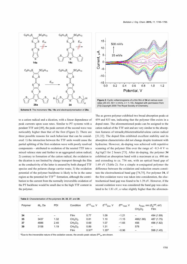
Electropolymerisation of monomer compounds 14a, 14c and
28a [73] was attempted. Due to the high oxidation potential (see
Table 1) of the thiophene unit in the fused system 14a (2.18 V
vs Ag/AgCl), electropolymerisation for this compound was
unsuccessful (Scheme 8). Surprisingly, the other two mono-
mers, both with a similar, low Ep3ox – attributed to oxidation of
the terthiophene unit (14c (1.55 V vs Ag/AgCl) and 28a (1.52 V
vs Ag/AgCl)) – showed different behaviour upon repetitive
voltammetric cycling over the range of 0.0–1.6 V vs Ag/AgCl.
Although upon electrodeposition of 14c onto the surface of a
working electrode a red film appeared, it was non-polymeric in
nature. On the contrary, the electropolymerisation of 28a under
the same conditions exhibited a reproducible polymer growth of
34.
The CV of polymer 34 exhibited the characteristic electrochem-
ical signature of the TTF-unit – two reversible oxidation waves
Beilstein J. Org. Chem. 2015, 11, 1749–1766.
1755
Table 2: Characterisation of the polymers 34, 35, 37, and 39.
Polymer Mn, Da PDI Condition E1/21ox, V E1/2
2ox, V Epc1red, V λmax, nm (Eg
opt, eV)CH2Cl2 Film
34 – – Film 0.77 1.09 −1.21 – 494 (1.69)35 3437 1.32 CH2Cl2 0.81 1.10 −1.15 466(1.86) 487 (1.75)37 4886 2.40 CH2Cl2 0.69 1.07 −1.65 456 496 (1.82)39 3158 1.19 CH2Cl2 0.89 1.31 – 578 –
Film 0.91a 1.35a −0.96 – 598 (1.45)aDue to the irreversible nature of the oxidation waves, the anodic peak values Epa
ox are shown.
Scheme 8: The monomers 14a, 14c and electropolymerisation of 28a.
to a cation radical and a dication, with a linear dependence of
peak currents upon scan rates. Similar to PT systems with a
pendant TTF unit [49], the peak current of the second wave was
noticeably higher than that of the first (Figure 2). There are
three possible reasons for such behaviour that can be consid-
ered: 1) the interaction between the TTF units would cause the
partial splitting of the first oxidation wave with poorly resolved
components – attributed to oxidation of the neutral TTF into a
mixed valence state and further to an aggregated cation radical;
2) contrary to formation of the cation radical, the oxidation to
the dication is not limited by charge transport through the film
as the conductivity of the latter is ensured by both charged TTF
species and the polaron charge carrier route; 3) the oxidation
potential of the polymer backbone is likely to be in the same
region as the potential for TTF2+ formation, although the contri-
bution to the current from the normally irreversible oxidation of
the PT backbone would be small due to the high TTF content in
the polymer.
Figure 2: Cyclic voltammograms of a thin film of 34 at various scanrates (25 mV, 50 × n mV/s, n = 1–10). Adapted with permission from[73].Copyright 2000 The Royal Society of Chemistry.
The as grown polymer exhibited two broad absorption peaks at
459 and 833 nm, indicating that the polymer film exists in a
doped state. The aforementioned peaks can be assigned to the
cation radical of the TTF unit and are very similar to the absorp-
tion features of tetraalkylthiotetrathiafulvalene cation radical
[31,32]. The doped film exhibited excellent stability and its
absorption characteristics did not change despite treatment with
hydrazine. However, de-doping was achieved with repetitive
scanning of the polymer film over the range of −0.3–0 V vs
Ag/AgCl for 2 hours [73]. After de-doping, the polymer 34
exhibited an absorption band with a maximum at ca. 490 nm
and extending to ca. 736 nm, with an optical band gap of
1.69 eV (Table 2). For a simple π-conjugated polymer the
difference between the oxidation and reduction onsets consti-
tute the electrochemical band gap [74,75]. For polymer 34, if
the first oxidation wave was taken into consideration, the elec-
trochemical band gap was found to be 1.39 eV. However, if the
second oxidation wave was considered the band gap was calcu-
lated to be 1.81 eV, a value slightly higher than the aforemen-
Beilstein J. Org. Chem. 2015, 11, 1749–1766.
1756
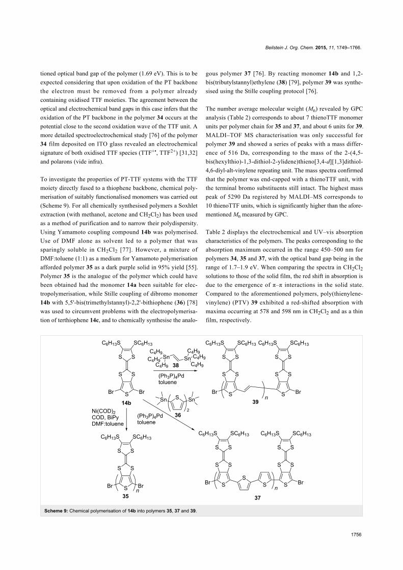
Scheme 9: Chemical polymerisation of 14b into polymers 35, 37 and 39.
tioned optical band gap of the polymer (1.69 eV). This is to be
expected considering that upon oxidation of the PT backbone
the electron must be removed from a polymer already
containing oxidised TTF moieties. The agreement between the
optical and electrochemical band gaps in this case infers that the
oxidation of the PT backbone in the polymer 34 occurs at the
potential close to the second oxidation wave of the TTF unit. A
more detailed spectroelectrochemical study [76] of the polymer
34 film deposited on ITO glass revealed an electrochemical
signature of both oxidised TTF species (TTF+•, TTF2+) [31,32]
and polarons (vide infra).
To investigate the properties of PT-TTF systems with the TTF
moiety directly fused to a thiophene backbone, chemical poly-
merisation of suitably functionalised monomers was carried out
(Scheme 9). For all chemically synthesised polymers a Soxhlet
extraction (with methanol, acetone and CH2Cl2) has been used
as a method of purification and to narrow their polydispersity.
Using Yamamoto coupling compound 14b was polymerised.
Use of DMF alone as solvent led to a polymer that was
sparingly soluble in CH2Cl2 [77]. However, a mixture of
DMF:toluene (1:1) as a medium for Yamamoto polymerisation
afforded polymer 35 as a dark purple solid in 95% yield [55].
Polymer 35 is the analogue of the polymer which could have
been obtained had the monomer 14a been suitable for elec-
tropolymerisation, while Stille coupling of dibromo monomer
14b with 5,5'-bis(trimethylstannyl)-2,2'-bithiophene (36) [78]
was used to circumvent problems with the electropolymerisa-
tion of terthiophene 14c, and to chemically synthesise the analo-
gous polymer 37 [76]. By reacting monomer 14b and 1,2-
bis(tributylstannyl)ethylene (38) [79], polymer 39 was synthe-
sised using the Stille coupling protocol [76].
The number average molecular weight (Mn) revealed by GPC
analysis (Table 2) corresponds to about 7 thienoTTF monomer
units per polymer chain for 35 and 37, and about 6 units for 39.
MALDI–TOF MS characterisation was only successful for
polymer 39 and showed a series of peaks with a mass differ-
ence of 516 Da, corresponding to the mass of the 2-(4,5-
bis(hexylthio)-1,3-dithiol-2-ylidene)thieno[3,4-d][1,3]dithiol-
4,6-diyl-alt-vinylene repeating unit. The mass spectra confirmed
that the polymer was end-capped with a thienoTTF unit, with
the terminal bromo substituents still intact. The highest mass
peak of 5290 Da registered by MALDI–MS corresponds to
10 thienoTTF units, which is significantly higher than the afore-
mentioned Mn measured by GPC.
Table 2 displays the electrochemical and UV–vis absorption
characteristics of the polymers. The peaks corresponding to the
absorption maximum occurred in the range 450–500 nm for
polymers 34, 35 and 37, with the optical band gap being in the
range of 1.7–1.9 eV. When comparing the spectra in CH2Cl2
solutions to those of the solid film, the red shift in absorption is
due to the emergence of π–π interactions in the solid state.
Compared to the aforementioned polymers, poly(thienylene-
vinylene) (PTV) 39 exhibited a red-shifted absorption with
maxima occurring at 578 and 598 nm in CH2Cl2 and as a thin
film, respectively.

Beilstein J. Org. Chem. 2015, 11, 1749–1766.
1757
Figure 3: Spectroelectrochemistry of polymers 37 (a) and 34 (b) as thin films deposited on the working electrode. Adapted with permission from [76].Copyright 2006 The American Chemical Society.
The CVs in CH2Cl2 solution of 35 and 37 (Table 2) revealed
two quasi-reversible oxidation waves that are shifted to lower
potentials compared to the corresponding reversible oxidation
waves of monomer 14b (+0.91 and +1.31 V, see Table 1).
Monomer 14b has a weaker donating ability due to the strong
electron-withdrawing inductive effect of the terminal bromo
substituents, while the PTV polymer 39 exhibited almost iden-
tical oxidation potentials to monomer 14b. On the other hand,
both oxidation waves of the TTF unit in polymers 35, 37, and
39 shifted to significantly higher potentials in comparison to
those of the non-brominated monomer compound 14a (+0.46
and +0.83 V, see Table 1) [54]. This can be explained by: 1) the
electron-withdrawing effect of the polymer backbone and 2) the
electrostatic interaction between the oxidised TTF units within
the polymer backbone. The degree to which these polymer oxi-
dation potentials shift is in the order 37 < 35 < 39, which
roughly follows the expected charge density of the doped
polymer backbone. The chronocoulometry experiment during
bulk electrolysis of 35 and 39 revealed that approximately two
electrons were released per monomer unit; this is much more
than one would expect from a simple PT that normally donates
one electron per 3–10 thiophene units [80]. To the best of our
knowledge, 35 is the most dopable polythiophene in the litera-
ture, with respect to the level of oxidation that is achieved per
repeating unit, the excellent electrochemical reversibility
observed, and the modest potential window in which the highly
doped state is attained. Even for a stable doped system, for
example a PEDOT sample heavily doped with polystyrenesul-
fonic (PSSH) or p-toluenesulfonic (TosH) acid, the doping level
is 3–5 units per one positive charge [81,82]. So, the presence of
TTF units fused to each thiophene of the PT backbone creates a
polymer with a greatly enhanced p-doping ability. The direct
fusion in this case of two electroactive units (TTF and PT)
inhibits any electrochemical activity from the polymer back-
bone and the electrochemistry of the material is dominated by
the TTF unit.
The inhibition of the polymer backbone’s electrochemical
activity was confirmed by spectroelectrochemistry of 39, which
indicated no change of the π–π* transition upon applying poten-
tials up to +2.0 V. The CV of 39 shows an irreversible first oxi-
dation wave, and the band gap calculated from the first oxi-
dation onset agreed well with the optical band gap. The former
indicates the possibility of significant interchain interactions
between the TTF unit and the polymer backbone.
Upon oxidation, the film of polymer 37 exhibited a broad ill-
defined band extending from 700 nm into the near infrared
range. The intensity of the π–π* transition in this case dimin-
ished upon oxidation, but this band still remained the most
intense feature of the spectrum across the entire potential range
(Figure 3a). The spectoelectrochemistry of polymer 34 revealed
more drastic changes in the spectra upon oxidation of the film,
where the resolved absorption signature of a cation radical,
dication and polaron can be observed (Figure 3b). As the
applied potential is increased, two peaks appear: one at 460 nm
that overlaps with the backbone π–π* transition, and a second
centred at 800 nm. Those peaks were observed in the spectrum
of the doped polymer film (Figure 3b) and could be assigned to
the absorption of the cation radical of the TTF unit. With further
increase in the applied potential the TTF cation radical UV–vis
signature diminishes and a strong absorption band at 700 nm,
Beilstein J. Org. Chem. 2015, 11, 1749–1766.
1758
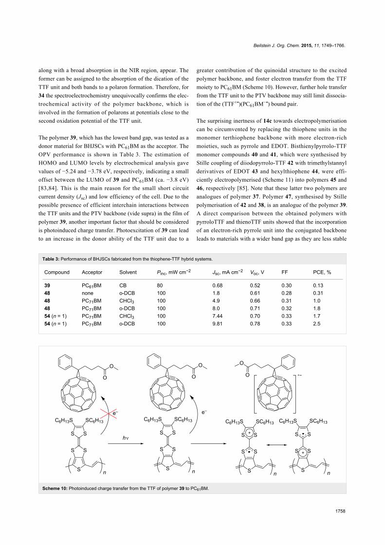
Table 3: Performance of BHJSCs fabricated from the thiophene-TTF hybrid systems.
Compound Acceptor Solvent Pinc, mW cm−2 Jsc, mA cm−2 Voc, V FF PCE, %
39 PC61BM CB 80 0.68 0.52 0.30 0.1348 none o-DCB 100 1.8 0.61 0.28 0.3148 PC71BM CHCl3 100 4.9 0.66 0.31 1.048 PC71BM o-DCB 100 8.0 0.71 0.32 1.854 (n = 1) PC71BM CHCl3 100 7.44 0.70 0.33 1.754 (n = 1) PC71BM o-DCB 100 9.81 0.78 0.33 2.5
Scheme 10: Photoinduced charge transfer from the TTF of polymer 39 to PC61BM.
along with a broad absorption in the NIR region, appear. The
former can be assigned to the absorption of the dication of the
TTF unit and both bands to a polaron formation. Therefore, for
34 the spectroelectrochemistry unequivocally confirms the elec-
trochemical activity of the polymer backbone, which is
involved in the formation of polarons at potentials close to the
second oxidation potential of the TTF unit.
The polymer 39, which has the lowest band gap, was tested as a
donor material for BHJSCs with PC61BM as the acceptor. The
OPV performance is shown in Table 3. The estimation of
HOMO and LUMO levels by electrochemical analysis gave
values of −5.24 and −3.78 eV, respectively, indicating a small
offset between the LUMO of 39 and PC61BM (ca. −3.8 eV)
[83,84]. This is the main reason for the small short circuit
current density (Jsc) and low efficiency of the cell. Due to the
possible presence of efficient interchain interactions between
the TTF units and the PTV backbone (vide supra) in the film of
polymer 39, another important factor that should be considered
is photoinduced charge transfer. Photoexcitation of 39 can lead
to an increase in the donor ability of the TTF unit due to a
greater contribution of the quinoidal structure to the excited
polymer backbone, and foster electron transfer from the TTF
moiety to PC61BM (Scheme 10). However, further hole transfer
from the TTF unit to the PTV backbone may still limit dissocia-
tion of the (TTF+•)(PC61BM−•) bound pair.
The surprising inertness of 14c towards electropolymerisation
can be circumvented by replacing the thiophene units in the
monomer terthiophene backbone with more electron-rich
moieties, such as pyrrole and EDOT. Bisthienylpyrrolo-TTF
monomer compounds 40 and 41, which were synthesised by
Stille coupling of diiodopyrrolo-TTF 42 with trimethylstannyl
derivatives of EDOT 43 and hexylthiophene 44, were effi-
ciently electropolymerised (Scheme 11) into polymers 45 and
46, respectively [85]. Note that these latter two polymers are
analogues of polymer 37. Polymer 47, synthesised by Stille
polymerisation of 42 and 38, is an analogue of the polymer 39.
A direct comparison between the obtained polymers with
pyrroloTTF and thienoTTF units showed that the incorporation
of an electron-rich pyrrole unit into the conjugated backbone
leads to materials with a wider band gap as they are less stable

Beilstein J. Org. Chem. 2015, 11, 1749–1766.
1759
Scheme 11: Electropolymerisation of 40 and 41 into polymers 45 and 46, respectively, and Stille polymerisation of 42 into polymer 47.
Scheme 12: The synthesis of polymer 48.
to n-doping. The pyrrole unit lowers the oxidation potentials of
the TTF moieties but the electrochemical dominance of the TTF
is lost in the pyrrolo-TTF polymers.
Another analogue of polymer 37 includes the 2,5-bis(2-octyl-
dodecyl)-1,4-dioxopyrrolo[3,4-c]pyrrole (DPP) unit incorpo-
rated within the PT backbone [86]. The polymer 48 was
prepared by Suzuki coupling polymerisation of diboronic ester
49 and dibromothieno-TTF 50 (Scheme 12). The latter was
synthesised following the aforementioned synthetic pathway A.
The incorporation of the DPP π-acceptor into the conjugated
backbone led to a polymer with a narrow optical band gap
(Egopt = 1.32 eV in CH2Cl2 solution), with the expected lower
value of Egopt = 1.26 eV in the film due to π–π stacking interac-
tions. The value of the HOMO/LUMO levels (−5.13/−3.49 eV)
in the film were noticeably different from those in solution
(−4.95/−3.55 eV), which suggested significant donor–acceptor
interactions in the solid phase between the DPP and TTF units.
OFET device fabrication employing polymer 48 exhibited
p-type semiconductor behaviour, with the best performance
from devices using the bottom contact top gate configuration
[87]. The hole mobility values calculated in the saturated region
were found to be 3.8 × 10⁻² and 5.3 × 10⁻² cm2 V−1 s−1 for
OFETs fabricated via spincoating the semiconductor from solu-
tion in chlorobenzene and chloroform, respectively. The strong

Beilstein J. Org. Chem. 2015, 11, 1749–1766.
1760
Figure 4: Tapping mode AFM height images of polymer 48 film spin-coated from chlorobenzene (left) and chloroform (right) solutions on ODTStreated SiO2 substrate. Reproduced with permission from [87]. Copyright 2015 The American Chemical Society.
propensity of 48 to aggregation led to the tightly packed grain
morphology of the film cast from chlorobenzene with small
sized crystalline domains (Figure 4). On the contrary, using
chloroform the high solvation energy of the TTF unit and the
carbonyl groups of the DPP moieties made the rate of nucle-
ation lower compared to the rate of grain growth, so the size of
the crystalline domain in the film was higher in this case. These
larger crystalline domains in films spin-coated from chloroform
were beneficial for field effect mobility.
None of the OFETs showed any n-type mobility. The extended
character of the HOMO residing on the dithienyl-thieno-TTF
unit and the localised nature of the LUMO led to
donor–acceptor interactions in the solid phase, making it impos-
sible for efficient overlap between LUMOs, which would
normally be required for an efficient n-type semiconductor.
BHJSCs were fabricated from 48 as the electron donor and
PC71BM as the electron acceptor using ortho-diclorobenzene
(o-DCB) and chloroform as solvents (Table 3). The devices
prepared with o-DCB showed up to a two-fold increase in
power conversion efficiency (PCE) compared to those obtained
by spincoating the blend from chloroform, which is due to a
more homogeneous blend morphology leading to improved
charge carrier transport and increased Jsc. Since the use of
o-DCB as the solvent for spincoating provided better perfor-
mance for BHJSCs than chloroform, it was used for the fabrica-
tion of a single material organic solar cell (SMOSC) (Table 3).
The SMOSC performance is modest compared to that of similar
devices fabricated using donor–acceptor block copolymers [88-
90]. Nevertheless, the value of the PCE (0.31%) is higher than
one would expect from a SMOSC fabricated from polymer 48
as a semiconductor, since it has no obvious donor–acceptor
phase separation and is lacking efficient electron mobility.
TTF-oligothiophene systems with well-definedstructuresThe monodisperse analogue of polymer 34, bearing two TTF
units and capped with dodecyl chains at the terminal positions,
was synthesised using chemical coupling protocols, or alter-
natively via electrochemical oxidation of terthiophene 28b
(Scheme 13) [72]. The latter was synthesised by the aforemen-
tioned synthetic pathway C.
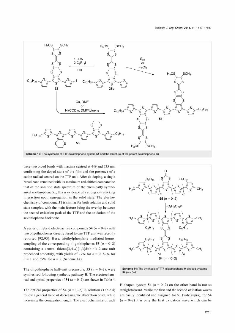
The electrochemical method for the preparation of sexithio-
phene 51 was achieved by potentiostatic oxidative electrodimer-
ization of 28b in a mixture of 2:1 CH2Cl2/hexane, with 0.1 M
tetrabutylammonium hexafluorophosphate as the supporting
electrolyte. On a larger scale, chemical oxidation by FeCl3 in
nitrobenzene was used which after purification, afforded 51 in a
24% yield. Lithiation of compound 28b with LDA and succes-
sive trapping of the aryllithium compound with perfluorohexyl
iodide afforded iodoterthiophene 52 in a 74% yield. Compound
52 was used to explore other possibilities for synthesising
sexithiophene 51, including Ullmann and Yamamoto coupling,
which provided 51 in 43 and 10% yield, respectively. Sexithio-
phene 51 exhibited a strong propensity to aggregate even in
chloroform solution, hence an interpretable 1H NMR spectrum
was only obtained in a mixture of CDCl3 with CS2.
In CH2Cl2 solution, the chemically synthesised product showed
a π–π* transition peak at 443 nm, with a HOMO–LUMO gap of
2.32 eV, a value very similar to that of the parent sexithiophene
53 [91]. For the electrochemically prepared film of 51, there
Beilstein J. Org. Chem. 2015, 11, 1749–1766.
1761
Scheme 13: The synthesis of TTF-sexithiophene system 51 and the structure of the parent sexithiophene 53.
were two broad bands with maxima centred at 449 and 735 nm,
confirming the doped state of the film and the presence of a
cation radical centred on the TTF unit. After de-doping, a single
broad band remained with its maximum red-shifted compared to
that of the solution state spectrum of the chemically synthe-
sised sexithiophene 51; this is evidence of a strong π–π stacking
interaction upon aggregation in the solid state. The electro-
chemistry of compound 51 is similar for both solution and solid
state samples, with the main feature being the overlap between
the second oxidation peak of the TTF and the oxidation of the
sexithiophene backbone.
A series of hybrid electroactive compounds 54 (n = 0–2) with
two oligothiophenes directly fused to one TTF unit was recently
reported [92,93]. Here, triethylphosphite mediated homo-
coupling of the corresponding oligothiophenes 55 (n = 0–2)
containing a central thieno[3,4-d][1,3]dithiole-2-one unit
proceeded smoothly, with yields of 77% for n = 0, 82% for
n = 1 and 39% for n = 2 (Scheme 14).
The oligothiophene half-unit precursors, 55 (n = 0–2), were
synthesised following synthetic pathway B. The electrochem-
ical and optical properties of 54 (n = 0–2) are shown in Table 4.
The optical properties of 54 (n = 0–2) in solution (Table 4)
follow a general trend of decreasing the absorption onset, while
increasing the conjugation length. The electrochemistry of each
Scheme 14: The synthesis of TTF-oligothiophene H-shaped systems54 (n = 0–2).
H-shaped system 54 (n = 0–2) on the other hand is not so
straightforward. While the first and the second oxidation waves
are easily identified and assigned for 51 (vide supra), for 54
(n = 0–2) it is only the first oxidation wave which can be
Beilstein J. Org. Chem. 2015, 11, 1749–1766.
1762
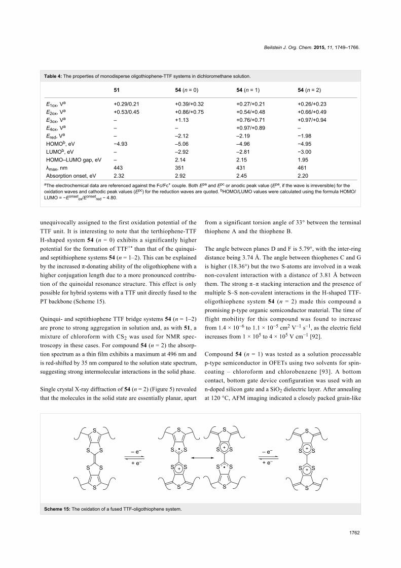
Table 4: The properties of monodisperse oligothiophene-TTF systems in dichloromethane solution.
51 54 (n = 0) 54 (n = 1) 54 (n = 2)
E1ox, Va +0.29/0.21 +0.39/+0.32 +0.27/+0.21 +0.26/+0.23E2ox, Va +0.53/0.45 +0.86/+0.75 +0.54/+0.48 +0.66/+0.49E3ox, Va – +1.13 +0.76/+0.71 +0.97/+0.94E4ox, Va – – +0.97/+0.89 –Ered, Va – –2.12 –2.19 −1.98HOMOb, eV −4.93 –5.06 –4.96 −4.95LUMOb, eV – –2.92 –2.81 −3.00HOMO–LUMO gap, eV – 2.14 2.15 1.95λmax, nm 443 351 431 461Absorption onset, eV 2.32 2.92 2.45 2.20
aThe electrochemical data are referenced against the Fc/Fc+ couple. Both Epa and Epc or anodic peak value (Epa, if the wave is irreversible) for theoxidation waves and cathodic peak values (Epc) for the reduction waves are quoted. bHOMO/LUMO values were calculated using the formula HOMO/LUMO = −Eonset
ox/Eonsetred − 4.80.
Scheme 15: The oxidation of a fused TTF-oligothiophene system.
unequivocally assigned to the first oxidation potential of the
TTF unit. It is interesting to note that the terthiophene-TTF
H-shaped system 54 (n = 0) exhibits a significantly higher
potential for the formation of TTF+• than that of the quinqui-
and septithiophene systems 54 (n = 1–2). This can be explained
by the increased π-donating ability of the oligothiophene with a
higher conjugation length due to a more pronounced contribu-
tion of the quinoidal resonance structure. This effect is only
possible for hybrid systems with a TTF unit directly fused to the
PT backbone (Scheme 15).
Quinqui- and septithiophene TTF bridge systems 54 (n = 1–2)
are prone to strong aggregation in solution and, as with 51, a
mixture of chloroform with CS2 was used for NMR spec-
troscopy in these cases. For compound 54 (n = 2) the absorp-
tion spectrum as a thin film exhibits a maximum at 496 nm and
is red-shifted by 35 nm compared to the solution state spectrum,
suggesting strong intermolecular interactions in the solid phase.
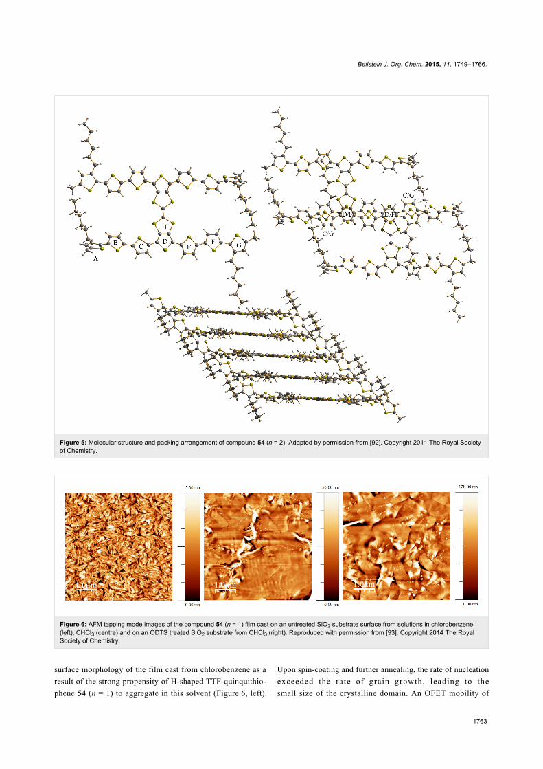
Single crystal X-ray diffraction of 54 (n = 2) (Figure 5) revealed
that the molecules in the solid state are essentially planar, apart
from a significant torsion angle of 33° between the terminal
thiophene A and the thiophene B.
The angle between planes D and F is 5.79°, with the inter-ring
distance being 3.74 Å. The angle between thiophenes C and G
is higher (18.36°) but the two S-atoms are involved in a weak
non-covalent interaction with a distance of 3.81 Å between
them. The strong π–π stacking interaction and the presence of
multiple S–S non-covalent interactions in the H-shaped TTF-
oligothiophene system 54 (n = 2) made this compound a
promising p-type organic semiconductor material. The time of
flight mobility for this compound was found to increase
from 1.4 × 10⁻⁶ to 1.1 × 10⁻⁵ cm2 V−1 s−1, as the electric field
increases from 1 × 10⁵ to 4 × 10⁵ V cm−1 [92].
Compound 54 (n = 1) was tested as a solution processable
p-type semiconductor in OFETs using two solvents for spin-
coating – chloroform and chlorobenzene [93]. A bottom
contact, bottom gate device configuration was used with an
n-doped silicon gate and a SiO2 dielectric layer. After annealing
at 120 °C, AFM imaging indicated a closely packed grain-like
Beilstein J. Org. Chem. 2015, 11, 1749–1766.
1763
Figure 5: Molecular structure and packing arrangement of compound 54 (n = 2). Adapted by permission from [92]. Copyright 2011 The Royal Societyof Chemistry.
Figure 6: AFM tapping mode images of the compound 54 (n = 1) film cast on an untreated SiO2 substrate surface from solutions in chlorobenzene(left), CHCl3 (centre) and on an ODTS treated SiO2 substrate from CHCl3 (right). Reproduced with permission from [93]. Copyright 2014 The RoyalSociety of Chemistry.
surface morphology of the film cast from chlorobenzene as a
result of the strong propensity of H-shaped TTF-quinquithio-
phene 54 (n = 1) to aggregate in this solvent (Figure 6, left).
Upon spin-coating and further annealing, the rate of nucleation
exceeded the rate of grain growth, leading to the
small size of the crystalline domain. An OFET mobility of

Beilstein J. Org. Chem. 2015, 11, 1749–1766.
1764
1.41 × 10⁻⁴ cm2 V−1 s−1 calculated in the saturation region was
observed. An increase in the field effect mobility (to
µ = 1.17 × 10⁻³ cm2 V−1 s−1) by almost an order of magnitude
was observed in devices cast from chloroform. As with polymer
48, tapping mode AFM of the organic semiconductor film spin-
coated from this solvent revealed that, after annealing, the
surface morphology consisted of large crystalline domains with
a smooth grain boundary (Figure 6, centre). Such a striking
difference in morphology of the films cast from chlorobenzene
and CHCl3 is explained by the high energy of solvation of 54
(n = 1) in chloroform, which leads to a higher crystallisation
rate compared to the rate of nucleation during spin-coating and
subsequent annealing. When substrates with a pre-treated
n-octadecyltrichlorosilane (ODTS) SiO2 surface were used for
spin-coating from a CHCl3 solution, the surface morphology
remained essentially the same (Figure 6, right), with a further
increase in mobility (µ = 8.61 × 10⁻³ cm2 V−1 s−1) observed
due to the beneficial effects of large crystalline domains on the
field effect mobility.
Compound 54 (n = 1) was tested as a donor material in
BHJSCs. The results are presented in Table 3. Similar to
polymer 48, the device prepared by spin-coating the blend of 54
(n = 1) and PC71BM from solution in o-DCB showed a higher
performance than that fabricated with CHCl3, with a short
circuit current density (increased up to 9.81 mA cm−2) being
more affected by the solvent than the open circuit voltage
(0.78 V). AFM revealed a smoother surface morphology of the
donor–acceptor blend film cast from o-DCB than that when
chloroform was used as solvent.
ConclusionThe series of poly- and oligothiophene based compounds
bearing TTF units reported so far in the literature have been
discussed. The most interesting properties were exhibited by
polymers where TTF units were incorporated alongside the
conjugated backbone, allowing for the different charge trans-
port mechanisms on the basis of TTF mixed valence states and
polarons to be observed. Upon positioning the TTF unit in the
vicinity of the polymer backbone, a variation of electrochem-
ical behaviour is observed, including complete dominance by
the TTF units and, at times, independent activity of both elec-
troactive entities.
The initial idea of creating materials with hybrid charge trans-
port on the basis of the polaron mechanism and the mixed
valence state of doped TTF units has developed now into efforts
to use the TTF unit as a handle for controlling the morphology
of organic semiconductors in the solid state. The great chal-
lenge in this field is to design hybrid materials where the pos-
ition of the TTFs relative to the polymer backbone and the
choice of optimised processing conditions allow tuning of the
energy levels and the intrinsic charge carrier mobility in order
to achieve maximum device performance.
AcknowledgementsPJS thanks the Royal Society for a Wolfson Research Merit
Award and ALK thanks the EPSRC for funding (EP/I029141
and EP/K00042X).
References1. Skabara, P. J.; Arlin, J.-B.; Geerts, Y. H. Adv. Mater. 2013, 25,
1948–1954. doi:10.1002/adma.2012008622. Chen, T. A.; Rieke, R. D. J. Am. Chem. Soc. 1992, 114, 10087–10088.
doi:10.1021/ja00051a0663. McCullough, R. D.; Tristram-Nagle, S.; Williams, S. P.; Lowe, R. D.;
Jayaraman, M. J. Am. Chem. Soc. 1993, 115, 4910–4911.doi:10.1021/ja00064a070
4. Groenendaal, L.; Jonas, F.; Freitag, D.; Pielartzik, H.; Reynolds, J. R.Adv. Mater. 2000, 12, 481–494.doi:10.1002/(SICI)1521-4095(200004)12:7<481::AID-ADMA481>3.0.CO;2-C
5. Dang, M. T.; Hirsch, L.; Wantz, G.; Wuest, J. D. Chem. Rev. 2013, 113,3734–3765. doi:10.1021/cr300005u
6. Sirringhaus, H.; Tessler, N.; Friend, R. H. Science 1998, 280,1741–1744. doi:10.1126/science.280.5370.1741
7. Cho, S.; Lee, K.; Yuen, J.; Wang, G.; Moses, D.; Heeger, A. J.;Surin, M.; Lazzaroni, R. J. Appl. Phys. 2006, 100, 114503.doi:10.1063/1.2400796
8. Zotti, G.; Zecchin, S.; Schiavon, G.; Berlin, A.; Pagani, G.; Canavesi, A.Chem. Mater. 1995, 7, 2309–2315. doi:10.1021/cm00060a019
9. Schäferling, M.; Bäuerle, P. J. Mater. Chem. 2004, 14, 1132–1141.doi:10.1039/b313296j
10. Iraqi, A.; Crayston, J. A.; Walton, J. C. J. Mater. Chem. 1998, 8, 31–36.doi:10.1039/a703397d
11. Skabara, P. J.; Serebryakov, I. M.; Perepichka, I. F.; Sariciftci, N. S.;Neugebauer, H.; Cravino, A. Macromolecules 2001, 34, 2232–2241.doi:10.1021/ma0015931
12. Skabara, P. J.; Berridge, R.; Serebryakov, I. M.; Kanibolotsky, A. L.;Kanibolotskaya, L.; Gordeyev, S.; Perepichka, I. F.; Sariciftci, N. S.;Winder, C. J. Mater. Chem. 2007, 17, 1055–1062.doi:10.1039/B609858D
13. Goldenberg, L. M.; Skabara, P. J.; Roberts, D. M.; Berridge, R.;Ortí, E.; Viruela, P. M.; Pou-Amérigo, R. J. Mater. Chem. 2000, 10,2458–2465. doi:10.1039/b003914o
14. Berridge, R.; Wright, S. P.; Skabara, P. J.; Dyer, A.; Steckler, T.;Argun, A. A.; Reynolds, J. R.; Harrington, R. W.; Clegg, W.J. Mater. Chem. 2007, 17, 225–231. doi:10.1039/B613879A
15. Palermo, E. F.; Darling, S. B.; McNeil, A. J. J. Mater. Chem. C 2014, 2,3401–3406. doi:10.1039/c3tc32512a
16. Chan, S.-H.; Lai, C.-S.; Chen, H.-L.; Ting, C.; Chen, C.-P.Macromolecules 2011, 44, 8886–8891. doi:10.1021/ma201425d
17. Bijleveld, J. C.; Zoombelt, A. P.; Mathijssen, S. G. J.; Wienk, M. M.;Turbiez, M.; de Leeuw, D. M.; Janssen, R. A. J. J. Am. Chem. Soc.2009, 131, 16616–16617. doi:10.1021/ja907506r
18. Zhang, K.; Tieke, B.; Forgie, J. C.; Skabara, P. J.Macromol. Rapid Commun. 2009, 30, 1834–1840.doi:10.1002/marc.200900442

Beilstein J. Org. Chem. 2015, 11, 1749–1766.
1765
19. Zhang, K.; Tieke, B.; Forgie, J. C.; Vilela, F.; Parkinson, J. A.;Skabara, P. J. Polymer 2010, 51, 6107–6114.doi:10.1016/j.polymer.2010.10.054
20. Zhang, K.; Tieke, B.; Forgie, J. C.; Vilela, F.; Skabara, P. J.Macromolecules 2012, 45, 743–750. doi:10.1021/ma202387t
21. Cortizo-Lacalle, D.; Howells, C. T.; Gambino, S.; Vilela, F.;Vobecka, Z.; Findlay, N. J.; Inigo, A. R.; Thomson, S. A. J.;Skabara, P. J.; Samuel, I. D. W. J. Mater. Chem. 2012, 22,14119–14126. doi:10.1039/c2jm32374e
22. Forgie, J. C.; Skabara, P. J.; Stibor, I.; Vilela, F.; Vobecka, Z.Chem. Mater. 2009, 21, 1784–1786. doi:10.1021/cm9004823
23. Wudl, F.; Wobschall, D.; Hufnagel, E. J. J. Am. Chem. Soc. 1972, 94,670–672. doi:10.1021/ja00757a079
24. Ferraris, J.; Cowan, D. O.; Walatka, V.; Perlstein, J. H.J. Am. Chem. Soc. 1973, 95, 948–949. doi:10.1021/ja00784a066
25. Jérome, D. Chem. Rev. 2004, 104, 5565–5592. doi:10.1021/cr030652g26. Seo, H.; Hotta, C.; Fukuyama, H. Chem. Rev. 2004, 104, 5005–5036.
doi:10.1021/cr030646k27. Kini, A. M.; Geiser, U.; Wang, H. H.; Carlson, K. D.; Williams, J. M.;
Kwok, W. K.; Vandervoort, K. G.; Thompson, J. E.; Stupka, D. L.Inorg. Chem. 1990, 29, 2555–2557. doi:10.1021/ic00339a004
28. Bryce, M. R.; Devonport, W.; Goldenberg, L. M.; Wang, C.Chem. Commun. 1998, 945–951. doi:10.1039/a800536b
29. Christensen, C. A.; Becher, J.; Goldenberg, L. M.; Bryce, M. R.Chem. Commun. 1998, 509–510. doi:10.1039/A707504I
30. Beeby, A.; Bryce, M. R.; Christensen, C. A.; Cooke, G.;Duclairoir, F. M. A.; Rotello, V. M. Chem. Commun. 2002, 2950–2951.doi:10.1039/b209765f
31. Kanibolotsky, A.; Roquet, S.; Cariou, M.; Leriche, P.; Turrin, C.-O.;de Bettignies, R.; Caminade, A.-M.; Majoral, J.-P.; Khodorkovsky, V.;Gorgues, A. Org. Lett. 2004, 6, 2109–2112. doi:10.1021/ol049648x
32. Kimura, H.; Konishi, K.; Muraoka, S.-y.; Shirahata, T.; Misaki, Y.Chem. Lett. 2014, 43, 843–845. doi:10.1246/cl.140092
33. Yang, X.; Zhang, D.; Zhang, G.; Zhu, D. Sci. China: Chem. 2011, 54,596–602. doi:10.1007/s11426-011-4225-y
34. Nalluri, S. K. M.; Shivarova, N.; Kanibolotsky, A. L.; Zelzer, M.;Gupta, S.; Frederix, P. W. J. M.; Skabara, P. J.; Gleskova, H.;Ulijn, R. V. Langmuir 2014, 30, 12429–12437. doi:10.1021/la503459y
35. Inagi, S.; Naka, K.; Chujo, Y. J. Mater. Chem. 2007, 17, 4122–4135.doi:10.1039/b708640g
36. Kashimura, Y.; Goto, T.; Nakashima, H.; Furukawa, K.; Wang, E.;Li, H.; Hu, W.; Torimitsu, K. Jpn. J. Appl. Phys. 2010, 49, 01AB08.doi:10.1143/JJAP.49.01AB08
37. Jia, H.-P.; Forgie, J. C.; Liu, S.-X.; Sanguinet, L.; Levillain, E.;Le Derf, F.; Sallé, M.; Neels, A.; Skabara, P. J.; Decurtins, S.Tetrahedron 2012, 68, 1590–1594. doi:10.1016/j.tet.2011.11.087
38. Zhang, X.; Wang, C.; Lai, G.; Zhang, L.; Shen, Y. New J. Chem. 2010,34, 318–324. doi:10.1039/B9NJ00520J
39. Zhang, X.-C.; Wang, C.-Y.; Lai, G.-Q.; Zhang, L.; Shen, Y.-J.Polym. Bull. 2011, 66, 893–903. doi:10.1007/s00289-010-0322-x
40. Zhang, L.; Li, M.; Wang, C.; Lai, G.; Shen, Y. Polym. Bull. 2013, 70,353–369. doi:10.1007/s00289-012-0841-8
41. Hou, Y.; Wan, X.; Yang, M.; Ma, Y.; Huang, Y.; Chen, Y.Macromol. Rapid Commun. 2008, 29, 719–723.doi:10.1002/marc.200800023
42. Hou, Y.; Chen, Y.; Liu, Q.; Yang, M.; Wan, X.; Yin, S.; Yu, A.Macromolecules 2008, 41, 3114–3119. doi:10.1021/ma702864c
43. Yamamoto, T.; Shimizu, T. J. Mater. Chem. 1997, 7, 1967–1968.doi:10.1039/a704753c
44. Zotti, G.; Zecchin, S.; Schiavon, G.; Berlin, A.; Huchet, L.; Roncali, J.J. Electroanal. Chem. 2001, 504, 64–70.doi:10.1016/S0022-0728(01)00429-6
45. Roncali, J. J. Mater. Chem. 1999, 9, 1875–1893.doi:10.1039/a902747e
46. Bryce, M. R.; Chissel, A. D.; Gopal, J.; Kathirgamanathan, P.;Parker, D. Synth. Met. 1991, 39, 397–400.doi:10.1016/0379-6779(91)91766-4
47. Zhang, L.; Li, M.; Wang, C.; Wang, Y.; Shen, Y. J. Appl. Polym. Sci.2013, 127, 3356–3364. doi:10.1002/app.37803
48. Thobie-Gautier, C.; Gorgues, A.; Jubault, M.; Roncali, J.Macromolecules 1993, 26, 4094–4099. doi:10.1021/ma00068a004
49. Huchet, L.; Akoudad, S.; Roncali, J. Adv. Mater. 1998, 10, 541–545.doi:10.1002/(SICI)1521-4095(199805)10:7<541::AID-ADMA541>3.0.CO;2-1
50. Huchet, L.; Akoudad, S.; Levillain, E.; Roncali, J.; Emge, A.;Bäuerle, P. J. Phys. Chem. B 1998, 102, 7776–7781.doi:10.1021/jp982593u
51. Besbes, M.; Trippé, G.; Levillain, E.; Mazari, M.; Le Derf, F.;Perepichka, I. F.; Derdour, A.; Gorgues, A.; Sallé, M.; Roncali, J.Adv. Mater. 2001, 13, 1249–1252.doi:10.1002/1521-4095(200108)13:16<1249::AID-ADMA1249>3.0.CO;2-W
52. Trippé, G.; Le Derf, F.; Lyskawa, J.; Mazari, M.; Roncali, J.;Gorgues, A.; Levillain, E.; Sallé, M. Chem. – Eur. J. 2004, 10,6497–6509. doi:10.1002/chem.200400303
53. Sinha, J.; Lee, S. J.; Kong, H.; Swift, T. W.; Katz, H. E.Macromolecules 2013, 46, 708–717. doi:10.1021/ma3019365
54. Skabara, P. J.; Müllen, K. Synth. Met. 1997, 84, 345–346.doi:10.1016/S0379-6779(97)80774-6
55. Skabara, P. J.; Berridge, R.; McInnes, E. J. L.; West, D. P.;Coles, S. J.; Hursthouse, M. B.; Müllen, K. J. Mater. Chem. 2004, 14,1964–1969. doi:10.1039/b400809j
56. Shu, P.; Chiang, L.; Emge, T.; Holt, D.; Kistenmacher, T.; Lee, M.;Stokes, J.; Poehler, T.; Bloch, A.; Cowan, D.J. Chem. Soc., Chem. Commun. 1981, 920–921.doi:10.1039/c39810000920
57. Rovira, C.; Santalō, N.; Veciana, J. Tetrahedron Lett. 1989, 30,7249–7252. doi:10.1016/S0040-4039(01)93950-4
58. Rovira, C.; Veciana, J.; Santalo, N.; Tarres, J.; Cirujeda, J.; Molins, E.;Llorca, J.; Espinosa, E. J. Org. Chem. 1994, 59, 3307–3313.doi:10.1021/jo00091a017
59. Skabara, P. J.; Müllen, K.; Bryce, M. R.; Howard, J. A. K.;Batsanov, A. S. J. Mater. Chem. 1998, 8, 1719–1724.doi:10.1039/a803027h
60. Skabara, P. J.; Serebryakov, I. M.; Roberts, D. M.; Perepichka, I. F.;Coles, S. J.; Hursthouse, M. B. J. Org. Chem. 1999, 64, 6418–6424.doi:10.1021/jo990198+
61. O'Connor, B. R.; Jones, F. N. J. Org. Chem. 1970, 35, 2002–2005.doi:10.1021/jo00831a062
62. Lee, A. W. M.; Chan, W. H.; Wong, H. C. Synth. Commun. 1988, 18,1531–1536. doi:10.1080/00397918808081310
63. Liu, B.; Wu, B.; Xu, J.; Wu, Z.; Zhao, Y.; Zheng, X.; Wang, H.J. Raman Spectrosc. 2010, 41, 1185–1193. doi:10.1002/jrs.2580
64. Fox, M. A.; Pan, H.-l. J. Org. Chem. 1994, 59, 6519–6527.doi:10.1021/jo00101a009
65. Jeppesen, J. O.; Takimiya, K.; Jensen, F.; Brimert, T.; Nielsen, K.;Thorup, N.; Becher, J. J. Org. Chem. 2000, 65, 5794–5805.doi:10.1021/jo000742a
Beilstein J. Org. Chem. 2015, 11, 1749–1766.
1766
66. Salle, M.; Gorgues, A.; Jubault, M.; Boubekeur, K.; Batail, P.Tetrahedron 1992, 48, 3081–3090.doi:10.1016/S0040-4020(01)92250-1
67. Guziec, F. S., Jr.; Russo, J. M.; Torres, F. F.; Long, G. C.; Tellez, M. R.J. Chem. Soc., Perkin Trans. 1 1989, 1068–1070.doi:10.1039/p19890001068
68. Serebryakov, I. M.; Skabara, P. J.; Perepichka, I. F.J. Chem. Soc., Perkin Trans. 2 1999, 1405–1410.doi:10.1039/a901178a
69. Vilela, F.; Skabara, P. J.; Mason, C. R.; Westgate, T. D. J.; Luquin, A.;Coles, S. J.; Hursthouse, M. B. Beilstein J. Org. Chem. 2010, 6,1002–1014. doi:10.3762/bjoc.6.113
70. Svenstrup, N.; Becher, J. Synthesis 1995, 215–235.doi:10.1055/s-1995-3910
71. Berridge, R.; Serebryakov, I. M.; Skabara, P. J.; Ortí, E.; Viruela, R.;Pou-Amérigo, R.; Coles, S. J.; Hursthouse, M. B. J. Mater. Chem.2004, 14, 2822–2830. doi:10.1039/b404545a
72. Kanibolotsky, A. L.; Kanibolotskaya, L.; Gordeyev, S.; Skabara, P. J.;McCulloch, I.; Berridge, R.; Lohr, J. E.; Marchioni, F.; Wudl, F.Org. Lett. 2007, 9, 1601–1604. doi:10.1021/ol070366h
73. Skabara, P. J.; Roberts, D. M.; Serebryakov, I. M.; Pozo-Gonzalo, C.Chem. Commun. 2000, 1005–1006. doi:10.1039/b001943g
74. Roncali, J. Chem. Rev. 1997, 97, 173–206. doi:10.1021/cr950257t75. Bredas, J.-L. Mater. Horiz. 2014, 1, 17–19. doi:10.1039/C3MH00098B76. Berridge, R.; Skabara, P. J.; Pozo-Gonzalo, C.; Kanibolotsky, A.;
Lohr, J.; McDouall, J. J. W.; McInnes, E. J. L.; Wolowska, J.;Winder, C.; Sariciftci, N. S.; Harrington, R. W.; Clegg, W.J. Phys. Chem. B 2006, 110, 3140–3152. doi:10.1021/jp057256h
77. Skabara, P. J.; Roberts, D. M.; Ray, A. K.; Umare, S. S.; Hassan, A. K.;Nabok, A. V.; Müllen, K. Tetrathiafulvalene Units. In Electronic, Opticaland Optoelectronic Polymers and Oligomers; Jabbour, G. E.;Sariciftci, N. S., Eds.; Materials Research Society: Michigan, 2002; Vol.665, pp 45–52.
78. Kotani, S.; Shiina, K.; Sonogashira, K. J. Organomet. Chem. 1992,429, 403–413. doi:10.1016/0022-328X(92)83188-N
79. Renaldo, A. F.; Labadie, J. W.; Stille, J. K. Org. Synth. 1989, 67,86–97. doi:10.15227/orgsyn.067.0086
80. Roncali, J. Chem. Rev. 1992, 92, 711–738. doi:10.1021/cr00012a00981. Zotti, G.; Zecchin, S.; Schiavon, G.; Louwet, F.; Groenendaal, L.;
Crispin, X.; Osikowicz, W.; Salaneck, W.; Fahlman, M. Macromolecules2003, 36, 3337–3344. doi:10.1021/ma021715k
82. Kim, E.-G.; Brédas, J.-L. J. Am. Chem. Soc. 2008, 130, 16880–16889.doi:10.1021/ja806389b
83. Han, G. D.; Collins, W. R.; Andrew, T. L.; Bulović, V.; Swager, T. M.Adv. Funct. Mater. 2013, 23, 3061–3069. doi:10.1002/adfm.201203251
84. Holliday, S.; Ashraf, R. S.; Nielsen, C. B.; Kirkus, M.; Röhr, J. A.;Tan, C.-H.; Collado-Fregoso, E.; Knall, A.-C.; Durrant, J. R.; Nelson, J.;McCulloch, I. J. Am. Chem. Soc. 2015, 137, 898–904.doi:10.1021/ja5110602
85. Kanibolotsky, A. L.; Forgie, J. C.; Gordeyev, S.; Vilela, F.;Skabara, P. J.; Lohr, J. E.; Petersen, B. M.; Jeppesen, J. O.Macromol. Rapid Commun. 2008, 29, 1226–1230.doi:10.1002/marc.200800154
86. Cortizo-Lacalle, D.; Arumugam, S.; Elmasly, S. E. T.;Kanibolotsky, A. L.; Findlay, N. J.; Inigo, A. R.; Skabara, P. J.J. Mater. Chem. 2012, 22, 11310–11315. doi:10.1039/c2jm31502e
87. Arumugam, S.; Cortizo-Lacalle, D.; Rossbauer, S.; Hunter, S.;Kanibolotsky, A. L.; Inigo, A. R.; Lane, P. A.; Anthopoulos, T. D.;Skabara, P. J. ACS Appl. Mater. Interfaces 2015.doi:10.1021/am5080562
88. Zhang, Q.; Cirpan, A.; Russell, T. P.; Emrick, T. Macromolecules 2009,42, 1079–1082. doi:10.1021/ma801504e
89. Wang, J.; Higashihara, T. Polym. Chem. 2013, 4, 5518–5526.doi:10.1039/c3py00979c
90. Sommer, M.; Huettner, S.; Thelakkat, M. J. Mater. Chem. 2010, 20,10788–10797. doi:10.1039/c0jm00665c
91. Mason, C. R.; Skabara, P. J.; Cupertino, D.; Schofield, J.;Meghdadi, F.; Ebner, B.; Sariciftci, N. S. J. Mater. Chem. 2005, 15,1446–1453. doi:10.1039/b415610b
92. Wright, I. A.; Skabara, P. J.; Forgie, J. C.; Kanibolotsky, A. L.;González, B.; Coles, S. J.; Gambino, S.; Samuel, I. D. W.J. Mater. Chem. 2011, 21, 1462–1469. doi:10.1039/C0JM02293D
93. Wright, I. A.; Findlay, N. J.; Arumugam, S.; Inigo, A. R.;Kanibolotsky, A. L.; Zassowski, P.; Domagala, W.; Skabara, P. J.J. Mater. Chem. C 2014, 2, 2674–2683. doi:10.1039/c3tc32571g
License and TermsThis is an Open Access article under the terms of the
Creative Commons Attribution License
(http://creativecommons.org/licenses/by/2.0), which
permits unrestricted use, distribution, and reproduction in
any medium, provided the original work is properly cited.
The license is subject to the Beilstein Journal of Organic
Chemistry terms and conditions:
(http://www.beilstein-journals.org/bjoc)
The definitive version of this article is the electronic one
which can be found at:
doi:10.3762/bjoc.11.191