polymatic plus pf – polymatic top - plasson · the electro fusion control units of type polymatic...
TRANSCRIPT

Rev.: 2006-001-GB
S c h w e i ß t e c h n o l o g i e G m b H
Ka r l -B r ö g e r -St r . 1 0 DE-3 6 3 0 4 A l sf e l d Te l : + 4 9 -6 6 3 1 -9 6 5 2 -0 Fa x :+ 4 9 -6 6 3 1 -9 6 5 2 -5 2
Universal EF Control Unit
PF – polymatic plus PF – polymatic top
with USB-Port
PF-Schweißtechnologie GmbH – Karl-Bröger-Str. 10 – DE-36304 Alsfeld
Tel.: +49-(0)6631-9652-0 Fax.: +49-(0)6631-9652-52

REV.: 2006-001-GB 2

REV.: 2006-001-GB 3
Contents
1 Introduction ........................................................................................ 4
1.1 Maintenance periods ............................................................................................................. 4
2 Scope of application and technical data .......................................... 5
2.1 Scope of application .............................................................................................................. 5 2.2 Input of welding parameters ................................................................................................... 5 2.3 Range of fitting dimensions ................................................................................................... 5 2.4 Technical Data ...................................................................................................................... 6 2.5 Data Recording...................................................................................................................... 7 2.6 Technical File - Polymatic Plus / Top (ISO/FDIS 12176-2 ) .................................................... 8
3 Important safeguards ........................................................................ 9
4 Controls and Plugs .......................................................................... 10
5 Connection to Power Supply .......................................................... 11
5.1 Generator Suitability .............................................................................................................12
6 Starting a welding process ............................................................. 13
6.1 Preparation ...........................................................................................................................13 6.2 Barcode-Mode ......................................................................................................................14 6.3 FUSAMATIC©-Mode .............................................................................................................16 6.4 Manual-Mode .......................................................................................................................19
7 Additional Functions ....................................................................... 22
7.1 Function Menu ......................................................................................................................22 7.2 Letter Input Field ..................................................................................................................23 7.3 Entering a Commission Number (Job Number) .....................................................................24 7.4 Manual input of the fitting code .............................................................................................25 7.5 Adjusting the display contrast ...............................................................................................25 7.6 Data transfer.........................................................................................................................26 7.7 System configuration ............................................................................................................29 7.8 Request: Worker Code .........................................................................................................33 7.9 Request: Set daylight time ....................................................................................................33 7.10 Request: Weld Number ........................................................................................................34 7.11 Request: Weather condition..................................................................................................34 7.12 Traceability System ..............................................................................................................35
8 Trouble shooting .............................................................................. 39
8.1 Using and replacing the reading pen .....................................................................................39 8.2 Replacing Welding Terminals ...............................................................................................39 8.3 Adapter.................................................................................................................................39 8.4 Start messages .....................................................................................................................40 8.5 Error messages ....................................................................................................................41
9 Supervisor Code .............................................................................. 42
10 Alphanumeric code table ................................................................ 43
11 Conformity Declaration ................................................................... 45

REV.: 2006-001-GB 4
1 Introduction
Dear customer,
we thank you for the confidence in our product and wish you a contented work with it.
The present instructions manual includes, beside the description of the use of the devices, important notes for your safety and the scope of application. Therefore, you should read carefully the present instructions manual before the first use of the device. In case of failure or interruption of the workflow read the appropriate chapter of this manual. Self-evidently we are ready to assist you at any time:
PF-Schweißtechnologie GmbH Karl-Bröger-Str. 10 DE-36304 Alsfeld Tel.: +49-6631-9652-0 Fax: +49-6631-9652-52 All notes and technical specification in this instructions manual were prepared with all necessary care. The manufacturer keeps the right to make technical changes at the device, which are not directly included into the present instructions manual.
1.1 Maintenance periods Please note, that the bought product is a technically demanding machine for field application. In accordance to the applicable standards like DVS 2208-1, BGV A3, ISO 12176-2 and most national and international standards, these machines have to be subjected to a periodical maintenance. The maintenance period is 12 month. When the machine is used quite often the maintenance should be carried out more often. During the maintenance the machine will be upgraded to the current technical state. Additionally you get a 3-month function guarantee for the maintained device. The maintenance and the related checks are important for you safety and the continuous working reliability of the control unit. Therefore the maintenance and all necessary repairs, have to be carried out by the manufacturer or a authorised service point.

REV.: 2006-001-GB 5
2 Scope of application and technical data
2.1 Scope of application The electro fusion control units of type Polymatic Plus are exclusively for the electro fusion of thermoplastic pipes (e.g. made of PE-HD, PE80. PE100 or PP) by use of electro fusion fittings with an welding voltage lower than 48V . The control units are conform to the standard DVS 2208-1 as well as the ISO 12176-2, which refer to the standards applicable for the electro fusion fittings to be used. It is not allowed to use the electro fusion controllers, to which the present instruction manual refers to, for an application not covered by the above stated terms. The manufacturer is not liable for the use of the machine out of the scope of application.
2.2 Input of welding parameters The electro fusion controllers of type Polymatic Plus provide the following means for entering the welding parameters: BARCODE (ISO-TR 13950, Type 2/5i, 24 digits) The barcode attached on the most electro fusion fittings in the market contains all necessary data for processing them. After reading the barcode with the reading device, the process data is automatically taken over by the control unit. The barcodes contains mainly the following data: Manufacturer, type, diameter, fusion voltage, fusion time (with temperature correction, if applicable), resistance and resistance tolerance. FUSAMATIC-System: By reading out the reference resistance in the connector pins of the FUSAMATIC-Fitting the control unit automatically takes over the welding data of the fitting. MANUAL Input of the barcode digits: If the barcode on the fitting or the barcode reading device is defect, it is possible to enter the barcode digits (if available) into the control unit manually. MANUAL Input of the fusion voltage and time: If none of the above stated methods are usable, it is possible to enter directly the fusion voltage and fusion time of the fitting to the control unit. Note: Not all Polymatic Plus control units provide the FUSAMATIC-system. Please, ask your local provider for further information. Control Units without FUSAMATIC-system carry two black PVC caps over the welding terminals. FUSAMATIC-Controllers provide one red and one black PVC cap.
2.3 Range of fitting dimensions For which range of fitting dimensions a electro fusion control unit can be used depends essentially on the power consumption to the used fittings itself. Since the power consumption of the fittings are different for different fitting manufacturers, a general statement concerning this point is hardly to make. In case of doubt, each single case has to be checked separately. For electro fusion control units of the type Polymatic Plus the following general statement can be made, with the assumption, that all welding processes were made one after the other, i.e. that the control unit is able to cool down during the preparation time of the next fitting: Use for dimension 20-630mm without any limit. From a diameter of 710mm and higher there must be provided longer off-times to ensure a cooling down of the control unit (Error message “Device too hot”). Before processing fittings in this dimension range, you have to check that the welding current of the fitting does not exceed the maximum output current of the control unit. All above made statements refer to an ambient temperature of 20°C.
REV.: 2006-001-GB 6
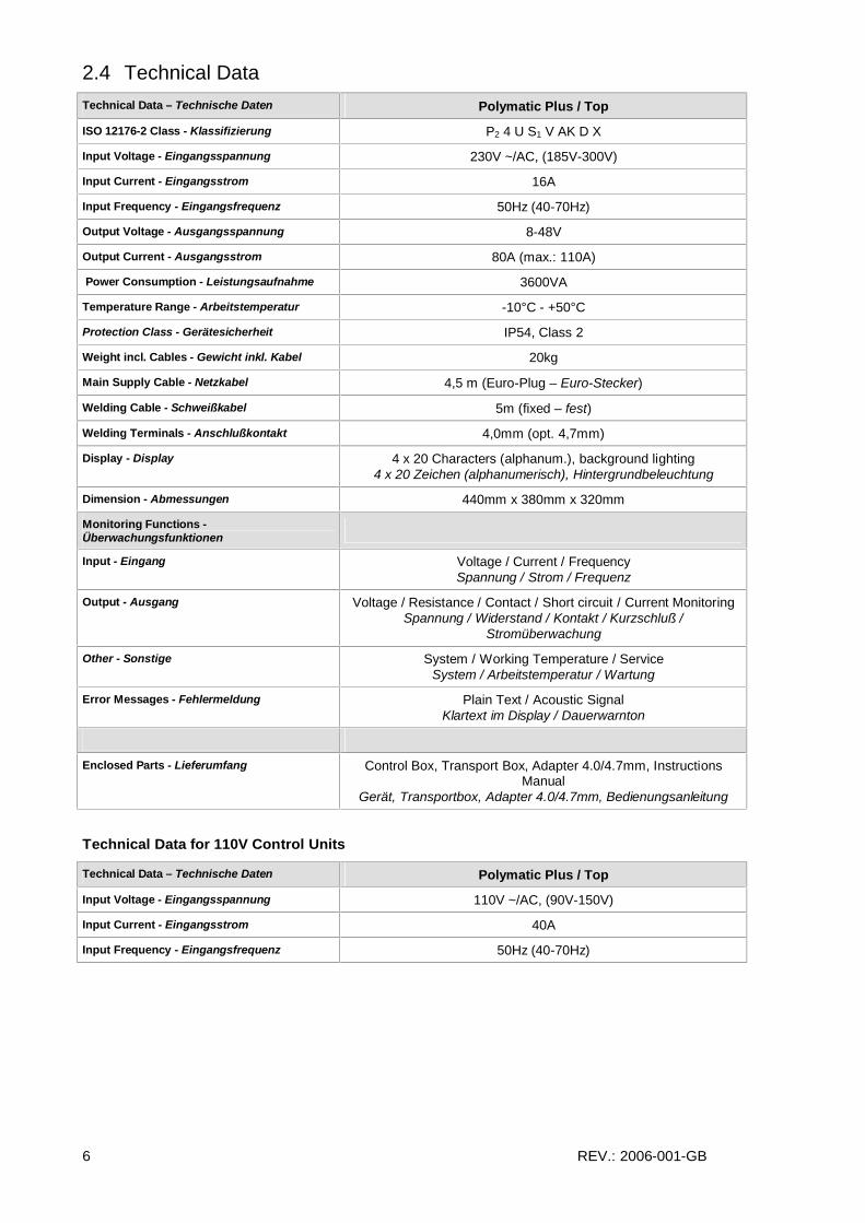
2.4 Technical Data
Technical Data – Technische Daten Polymatic Plus / Top
ISO 12176-2 Class - Klassifizierung P2 4 U S1 V AK D X
Input Voltage - Eingangsspannung 230V ~/AC, (185V-300V)
Input Current - Eingangsstrom 16A
Input Frequency - Eingangsfrequenz 50Hz (40-70Hz)
Output Voltage - Ausgangsspannung 8-48V
Output Current - Ausgangsstrom 80A (max.: 110A)
Power Consumption - Leistungsaufnahme 3600VA
Temperature Range - Arbeitstemperatur -10°C - +50°C
Protection Class - Gerätesicherheit IP54, Class 2
Weight incl. Cables - Gewicht inkl. Kabel 20kg
Main Supply Cable - Netzkabel 4,5 m (Euro-Plug – Euro-Stecker)
Welding Cable - Schweißkabel 5m (fixed – fest)
Welding Terminals - Anschlußkontakt 4,0mm (opt. 4,7mm)
Display - Display 4 x 20 Characters (alphanum.), background lighting 4 x 20 Zeichen (alphanumerisch), Hintergrundbeleuchtung
Dimension - Abmessungen 440mm x 380mm x 320mm
Monitoring Functions - Überwachungsfunktionen
Input - Eingang Voltage / Current / Frequency Spannung / Strom / Frequenz
Output - Ausgang Voltage / Resistance / Contact / Short circuit / Current Monitoring Spannung / Widerstand / Kontakt / Kurzschluß /
Stromüberwachung
Other - Sonstige System / Working Temperature / Service System / Arbeitstemperatur / Wartung
Error Messages - Fehlermeldung Plain Text / Acoustic Signal Klartext im Display / Dauerwarnton
Enclosed Parts - Lieferumfang Control Box, Transport Box, Adapter 4.0/4.7mm, Instructions Manual
Gerät, Transportbox, Adapter 4.0/4.7mm, Bedienungsanleitung
Technical Data for 110V Control Units
Technical Data – Technische Daten Polymatic Plus / Top
Input Voltage - Eingangsspannung 110V ~/AC, (90V-150V)
Input Current - Eingangsstrom 40A
Input Frequency - Eingangsfrequenz 50Hz (40-70Hz)

REV.: 2006-001-GB 7
2.5 Data Recording The electro fusion control box Polymatic Plus provides data recording for 1000 welding cycles and their traceability data conform ISO-12176-4:
Data Recording - Protokollierung Polymatic Plus / Top
Number of Reports – Anzahl der Protokolle 1000
Interface – Schnittstelle USB
Data format - Datenformat PDF / CSV
Recorded Data – Protokollierte Daten
Fusion Data - Schweißdaten
Voltage / Current / Nominal and Actual Welding Time / Mode / Resistance / Error Messages with 10 Voltage-Current Values
Spannung / Strom / Arbeit / Ist- und Sollzeit / Modus / Widerstand / Fehlermeldung mit 10 Spannungs- und Stromwerten
Fitting Data - Fittingdaten
Barcode Information (ISO/TR 13950) / Type / Dimension / Manufacturer
Barcodeziffern (ISO/TR 13950) / Typ / Dimension / Hersteller
Device Data - Gerätedaten
Serial Number / Inventory Number / Date of last Service / Working Hours / System Configuration
Geräte Nummer / Inventarnummer / Datum der letzten Wartung / Betriebsstunden / Systemeinstellung
Operator Code - Schweißer Code
Barcode (PF or ISO 12176-3) for operator identification and access to manual input and system configuration
Barcode (PF oder ISO 12176-3) für Schweißeridentifikation und Freigabe der Manuellen Eingabe und Systemeinstellung
Traceability Functions – Funktionen zur Bauteilrückverfolgung
Commission-Number (Job-Code) - Kommissionsnummer
Max. 40-digits (alphanumerical) by Barcode max. 40-stellig, alphanumerisch, Eingabe über Barcode
Operator Code – Schweißercode ISO-12176-3
Weather Condition – Witterung DVS 2207 / 2208
Welding Barcode – Schweißcode ISO-TR 13950
Traceability Barcode of Fitting - Chargencode des Fitting
ISO-12176-4
Traceability Barcode of 1st pipe - 1. Rohrcode
ISO-12176-4
Traceability Barcode of 2nd pipe - 2. Rohrcode
ISO-12176-4
3rd Traceability Code / Infotext – 3. Rohrcode / Infotext
ISO-12176-4
Pipe-Linking System Rohr-Ident-System
Polymatic Top only
Other Functions – Weitere Funktionen
Output Options – Ausgabeoptionen Whole Memory / Comm.-No. Gesamter Speicher / Kommissionsnummer
Commisson Number Input/Selection – Komm.-Nr. Eingabe/Auswahl
Barcode, Manual, Internal List of Comm.-No. For Selection Barcode, Manuell, Interne Liste von Komm.-Nr. zur Auswahl

REV.: 2006-001-GB 8
2.6 Technical File - Polymatic Plus / Top (ISO/FDIS 12176-2 )
Classification
Machine Type Classification
Polymatic Plus / Polymatic Top P2 4 U S1 V AK D X
Simulation Curved at 24V (Output voltage)
Duty Cycle at 100%, 60% and 30%
Additional Information
Soft Start: 2sec ramped Ambient Temperature Compensation: As stated in ISO/TR 13950 Fitting Temperature Compensation: No Fusion Data Recorder: 1000 fusion cycles, internal

REV.: 2006-001-GB 9
3 Important safeguards
Before turning on the welding device, please, read this operating instructions as well as the relevant safety and processing directions carefully.
Warning! With the use of electric tools you have to note the following basic safety direction to protect against electric shock, injury and fire.
1. Keep your working area in order ! Disorder involves a certain danger.
2. Consider the influence of environment ! Do not expose electro tools to rain. Do not use electro tools in wet or damp surroundings or in the neighbourhood of combustible liquids or gases.
3. Protect yourself against electric shock ! Avoid body contact with grounded components (e.g. radiators, metal pipes) or live cables. Do not carry the device, with the finger on the power switch. Pull out the plug when you do not use the tool or when changing the adapters and attachments.
4. Keep unauthorized people and children away ! Do not allow other people touch the device or cables – keep them away from your working place.
5. Store up your device safely ! Unused machines should be kept in a dry and locked room, inaccessible for children and unauthorized people.
6. Use permitted accessories only! Do only use accessories, especially current sources and lengthening cables, that are stated in the operating instructions or recommended by us. The use of attachments, that are not stated in the operating instructions, involves a certain danger for you. Do only use permitted and marked lengthening cables outdoors.
7. Do not expose the cables to avoidable loads ! Do not carry the machine with the cable and do not use the cable to pull out the plug. Protect the cables against heat, oil and sharp edges.
8. Lock after your tools carefully ! Keep your device clean. Follow the servicing instructions and the instructions for changing the tools. Keep oil and grease away from the straps.
9. Check your device for damages ! Check your tools before every use for damages and function of the protection devices and machine parts. All parts have to be mounted in the right way. They have to fulfil all conditions for a impeccable running of the tool. Damaged protection devices and machine parts have to be repaired or replaced by an authorized service point.

REV.: 2006-001-GB 10
4 Controls and Plugs
(1) DISPLAY (2) START (green) (3) STOP (red) (4) CURSOR-KEYS (n SELECT-key)
(8)
(9)
(7)
(5)
(6)
(5) Power Switch (6) USB Port (7) Welding Cable (8) Cable Holder (9) Power Supply Cable

REV.: 2006-001-GB 11
5 Connection to Power Supply
The connecting conditions of EVU, the VDE-directions, the accident prevention regulations, DIN/CEN-regulations as well as national regulations have to be considered.
The Electro Fusion Control Box has to be operated by certified operators referring to the national and international standards. The operator has to supervise the complete welding process.
The machine has to be operated within the following operation ranges:
Parameter 230V Control Units 110V Control Units
Input Voltage: 185V – 300V (AC) 90V – 150V (AC)
Input Frequency: 40Hz – 70Hz 40Hz – 70Hz
Ambient Temperature -10°C – +50°C -10°C – +50°C
Max Load 4000W 4000W
Caution: 110V Control Units shall not be used at 230V power supply and vice versa.
When operating on a electric distributor or the main power supply of nominal 230V, a min. 16 Amps slow fuse comprising a residual current-operated protective device (RCCB) should be used (110V: min. 32Amps). Extension Cables: To extend the power supply cable you have to follow the following rules:
Cable length Cross Section (230V) Cross Section (110V)
Up to 20m 3 x 1.5mm² 3 x 4mm²
20 to 50m 3 x 2.5mm² 3 x 4mm²
50-100m 3 x 4mm² -
It is not allowed to extend the welding cable! Important notes for the use of generators:
• First start generator, then plug in the device.
• No other machine or device shall be connected to the generator
• The idle running voltage should be regulated to 240V – 260V (AC) at nominal 230V (nominal 110V: 120V – 130V (AC)).
• Plug out welding device before turning off the generator.
• The usable generator power will decrease by 10% per 1000m height.
• Check the fuel level before starting the welding process.
REV.: 2006-001-GB 12
5.1 Generator Suitability
The Electro Fusion Controllers of type Polymatic Plus provide the following means to increase the generator suitability:
• Wide tolerance for input voltage and Input frequency.
• Display of current input voltage and frequency.
• Soft-Start for limitation of the generator load.
Despite this characteristics, the generators to be used have to fulfil the following requirements and recommends, in order to avoid damaged of the control unit and to ensure that the internal monitoring function of the control unit will not interrupt the welding process:
• suitable to drive inductive loads and phase cut systems
• no-load voltage adjustable to 240V – 260V at nominal 230V (nominal 110V: 120V – 130V (AC)).
• output current of 18 Amps at one phase at nominal 230V (nominal 110V: 36Amps).
• stable output voltage and engine speed, also at fast alternating loads
• synchronous generators with mechanical speed control preferred
• voltage peaks must no exceed 800V
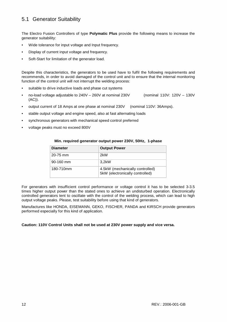
Min. required generator output power 230V, 50Hz, 1-phase
Diameter Output Power
20-75 mm 2kW
90-160 mm 3,2kW
180-710mm 4.5kW (mechanically controlled) 5kW (electronically controlled)
For generators with insufficient control performance or voltage control it has to be selected 3-3.5 times higher output power than the stated ones to achieve an undisturbed operation. Electronically controlled generators tent to oscillate with the control of the welding process, which can lead to high output voltage peaks. Please, test suitability before using that kind of generators.
Manufactures like HONDA, EISEMANN, GEKO, FISCHER, PANDA and KIRSCH provide generators performed especially for this kind of application.
Caution: 110V Control Units shall not be used at 230V power supply and vice versa.

REV.: 2006-001-GB 13
6 Starting a welding process
6.1 Preparation To start up the control box you have to follow the following steps in the given order:
1. Check device, cables and adapters optically and replace them in case of damage.
2. Unwind the power supply cable and the welding cable.
3. Connect the detachable welding cable to the control box.
4. Turn the power switch in OFF-position.
5. Start the generator before plugging in the control box. Wait until the generator output voltage has stabilized.
6. Plug in the Control Box
7. Switch on the power switch of the Control Box
Caution: 110V Control Units shall not be used at 230V power supply and vice versa.
After this procedure the machine will indicate its function by two bleeps and the following message will appear in the display:
PF polymatic Plus Version 2.04AH 25 Working hours 1000 Reports free
Row 1 and 2 show the type and firmware revision of the control box.
Row 3 counts the total amount of working hours (summed up fusion times).
Row 4 indicated the total number of free reports of the data recording system. In the case that the amount of free reports is smaller than 50, the letters of this row will flash. Press the red STOP-key to confirm the rare memory space. The reports should be printed out, because there is the danger of data loss if the memory control option is deactivated.
After ten seconds the above shown display will disappear. In the following there could be shown system messages like error messages of previous welding cycles or service notes, which can be aborted by pressing the red STOP-key.
When the following display message appears, the machine is ready to carry out a new welding process.
Connect Fitting 123AB45679 Report number 1
Row 1 tells you the actual process step. Instead of “Connect Fitting” there could appear “No Contact” also. To go further you have to connect an EF fitting to the welding cables.
Row 2 and 3 show the active the commission number.
Row 4 give you the report number, which is related to the current commission number.

REV.: 2006-001-GB 14
Welding Terminals:
- The contacts of the welding connector and the fitting plug must be clean – dirty or coated contacts can lead to overheating and burn at the connectors.
- Generally the terminals have to be protected against dirt. If there is a coating or loss of stick force on the connectors they have to be replaced.
- Use Adapters to connect certain fitting types. Adapters wear out with the time and have to be checked before every use.
Connect the welding terminals of the control unit to the pins of the fitting. Take care on a firm and proper fit.
FUSAMATIC-System
The welding with the FUSAMATIC©-Mode is only possible with FUSAMATIC©-fittings. The Option FUSAMATIC of the system configuration has to be enabled. The red terminal must be put on the fitting pin which is marked with the red ring.
Note: Fusamatic System is not available at all polymatic plus versions.
6.2 Barcode-Mode
Pay attention to the installation instructions of the fitting, special instructions (ISO, CEN, DVGW, DVS), European and national directions as well as the instructions of the manufacturers!
As long as no fitting is connected, no welding process can be started. When connecting the welding terminals to the pin at the fitting pay attention to a firm a proper fit. As soon as a fitting is connected, the following message appears in the display:
Fitting code 50 Hz 230 V +20°C 20.01.2003 15.25
Row 1 prompts you to read the fitting barcode. The respective procedure is described in the following sections. With the right connection of a FUSAMATIC©-fitting the welding device will automatically switch to the FUSAMATIC©-Mode.
Row 2 shows you the actual input frequency and voltage as well as the ambient temperature. In case of generator use check that the voltage is at about 240-260V at nominal 230V (nominal 110V: 120V – 130V (AC)).
Row 3 shows the date and time
Row 4 shows possible error messages
For welding in the Barcode-Mode, read in the barcode label, which is attached to the fitting you want to process. If it is not readable because of damage, you can use by the way of exception the readable barcode of an identical fitting of the same manufacturer or feed the numeric code manually into the device. It is forbidden to use the barcode of a different fitting.
If you read in a barcode which is defect or invalid the code error will be displayed and indicated by a bleep.
Using the reading pen:
Place the tip of the reading pen left or right beside the bar code. Move the reading pen with a constant speed over the whole barcode. Do not stop the movement or lift the reading pen off.

REV.: 2006-001-GB 15
You read-in the barcode by using the scanner or reading pen. If the device detects a valid barcode, it indicates its readiness by showing the following message:
Start Nom. Time : 0200 s +PF+ [ d063 20°C
Row 1 indicates that you have to press the green START-key to start the welding process. Before that you are obliged to check and compare the shown values with the ones given on the connected coupler.
Row 2 shows the nominal welding time.
Row 3 shows the manufacturer, type and diameter decoded from the barcode. The type information is shown like follows:
I Coupler T Tee
] End cap Y Reducer
.†. Saddle > Ray Trans
( Elbow ל TWD Tapping Saddle
There is also given the ambient temperature. If the fitting barcode provides temperature compensation, the nominal fusion time will be adapter to the ambient temperature.
Row 4 shows possible error messages.
After pressing the green START-key a message will remind you of your duty to fix and prepare the pipes according to the general guidelines:
Is the pipe scraped?
If you have any doubt about the right preparation, you can break off the procedure by actuating the red STOP-key. Confirm the proper preparation by pressing the green START-key.
Resistor Error
Now, the welding device begins to measure the fitting resistance. In the case that it is outside the valid range, the error will be indicated by a bleep and a appropriate message will appear in the display:
1,68< 2,00 < 1,93 Nom. time: 200 s Report Number 1 Resistor error
Row 1 shows in the middle the measured resistance. At the left and right the borders of the resistance range given in the barcode is shown.
Row 2 shows the nominal welding time.

REV.: 2006-001-GB 16
Row 3 shows the report number of the faulty process.
Row 4 shows “Resistor Error”
Plug the welding terminals out of fitting plugs. Check the connectors of the fitting and welding cable for dirt or coating. If the fitting causes another resistor error, it maybe defect. Replace it.
If no resistor error occurs, the welding device starts the welding process automatically. To avoid danger for your health, do not touch the fitting or cables during the welding process. The display shows the actual and nominal welding time:
Act. time: 0099 s Nom. time: 0200 s +PF+ [ d063
Row 1 shows the actual welding time, which is counted upwards.
Row 2 shows the nominal welding time.
Row 3 shows the manufacturer, type and diameter.
Row 4 shows possible error messages.
The welding process will stop automatically when the actual time reaches the nominal time. This will be indicated by two bleeps and the following message:
Act. time: 0200 s Nom. time: 0200 s Report number 1 20.01.2003 15.25
After stopping the welding process the data will be stored into the internal memory of the device. Pull off the welding connectors to go back to the start message.
6.3 FUSAMATIC©-Mode Note: Fusamatic System is not available at all polymatic plus versions.
Pay attention to the installation instructions of the fitting, special instructions (ISO, CEN, DVGW, DVS), European and national directions as well as the instructions of the manufacturers!
The welding with the FUSAMATIC©-Mode is only possible with FUSAMATIC©-fittings.
As long as no fitting is connected, no welding process can be started. When connecting the welding terminals to the pin at the fitting pay attention to a firm a proper fit. Connect the red welding terminal to the fitting connector with the red marking. Thus the welding device can detect the fitting type and its welding parameters. It will switch to the FUSAMATIC©-Mode automatically. This will be indicated by the following message:
START Nom. time: 200 s

REV.: 2006-001-GB 17
FUSA 40V 20°C
Row 1 indicates that you have to press the green START-key to start the welding process. Before that you are obliged to check and compare the shown values with the ones given on the connected coupler. In the case that these deviate or if a contact error is indicated in the lowest row of the display, a faulty or invalid reference resistance is read. Pull off the welding connector from the fitting plugs. Check the connectors of the fitting and welding cable for dirt or coating. If the fitting causes another contact error or differing parameters, it is defect. Replace it.
Row 2 shows the nominal welding time.
Row 3 shows the manufacturer FUSA and 40V to indicate the FUSAMATIC© mode and the ambient temperature.
Row 4 shows possible error messages.
You can confirm the correctness of the welding parameters by pressing the green START-key. The following message will remind you of your duty to fix and prepare the pipes according to the general guidelines:
Is the pipe scraped?
If you have any doubt about the right preparation, you can break off the procedure by actuating the red STOP-key.
Confirm the proper preparation by pressing the green START-key.
The welding device starts the welding process automatically. To avoid danger for your health, do not touch the fitting or cables during the welding process. The display shows the actual and nominal welding time:
Act. time: 0099 s Nom. time: 0200 s PLAS 40V
Row 1 shows the actual welding time, which is counted upwards.
Row 2 shows the nominal welding time.
Row 3 shows the manufacturer PLAS and 40V to indicate the FUSAMATIC© mode
Row 4 shows possible error messages.
The welding process will stop automatically when the actual time reaches the nominal time. This will be indicated by two bleeps and the following message:
Act. time: 0200 s Nom. time: 0200 s

REV.: 2006-001-GB 18
Report number 1 20.01.2003 15.25
After stopping the welding process the data will be stored into the internal memory of the device. Pull off the welding connectors to go back to the start message.

REV.: 2006-001-GB 19
6.4 Manual-Mode
Pay attention to the installation instructions of the fitting, special instructions (ISO, CEN, DVGW, DVS), European and national directions as well as the instructions of the manufacturers!
Welding with the manual input of welding parameters can only be done by using a special code number or reading in a barcode with manual input authorisation. In case that you do not find the supervisor code in the annex of this instructions, please contact our service.
As long as no fitting is connected, no welding process can be started. When connecting the welding terminals to the pin at the fitting pay attention to a firm a proper fit. As soon as a fitting is connected, the following message appears in the display:
Fitting code 50 Hz 230 V +20°C 20.01.2003 15.25
Row 1 prompts you to read the fitting barcode. The respective procedure is described in the following sections. With the right connection of a FUSAMATIC©-fitting the welding device will automatically switch to the FUSAMATIC©-Mode.
Row 2 shows you the actual input frequency and voltage as well as the ambient temperature. In case of generator use check that the voltage is at about 240-260V at nominal 230V (nominal 110V: 120V – 130V (AC)).
Row 3 shows the date and time
Row 4 shows possible error messages
After connecting the fitting, press the select key n to show the function menu in the display
>Comm. no. Print Fitting code
The function menu contains a list of available functions. The first three are shown in the display. The symbol > represents the cursor, which marks the menu item to be selected.
Use the v-keys to move the cursor to the item Man. Input and press select key n.
By following message you are asked to enter the code number or to read in a barcode with manual input authorisation (e.g. supervisor code / foreman code).
* Code number ABCDEFGHIJKLMNOPQRST UVWXYZ0123456789 $-/
A present barcode can be read in by using the reading pen or scanner. The input of the code number can be done by using the shown letter input field.

REV.: 2006-001-GB 20
If a valid code was entered, the display shows the entry fields of the welding parameters.
Weld Voltage U(V)= 40 V t(s)= 0020 s
Row 1 shows the name of the active entry field (here: Welding Voltage).
Row 2 shows the welding voltage entry field.
Row 3 shows the welding time entry field
An underlined or flashing digit marks the number to be changed
v Increases or decreases the digit which is marked.
34 Moves the marking to the left or right digit.
START Confirms the entered welding voltage.
After pressing the START-button the entry field for the welding voltage will be activated:
Weld time U(V)= 40 V t(s)= 0020 s
The value will be entered the same way as described above. After the confirmation with the START-button the welding parameters will be shown once again.
Start Nom. time : 20 s Weld voltage 40 V
Check carefully the correctness of the parameters before confirming them by pressing the green START-key. The following message will remind you of your duty to fix and prepare the pipes according to the general guidelines:
Is the pipe scraped?
If you have any doubt about the right preparation, you can break off the procedure by actuating the red STOP-key. Confirm the proper preparation by pressing the green START-key.

REV.: 2006-001-GB 21
The welding device starts the welding process automatically. To avoid danger for your health, do not touch the fitting or cables during the welding process. The display shows the actual and nominal welding time:
Act. time: 0009 s Nom. time: 0020 s Weld voltage 40V
Row 1 shows the actual welding time, which is counted upwards.
Row 2 shows the nominal welding time.
Row 3 shows the nominal welding voltage.
Row 4 shows possible error messages.
The welding process will stop automatically when the actual time reaches the nominal time. This will be indicated by two bleeps and the following message:
Act. time: 0020 s Nom. time: 0020 s Report number 1 20.01.2003 15.25
After stopping the welding process the data will be stored into the internal memory of the device. Pull off the welding connectors to go back to the start message.

REV.: 2006-001-GB 22
7 Additional Functions
7.1 Function Menu After connecting the device to the power supply and switching the device on, wait for the readiness of the device (two bleeps) and aboard all error messages with the red STOP-key.
Press the select key n to view the function menu in the display.
>Comm. no. Print Fitting code
The function menu contains a list of available functions. The first three are shown in the display. The symbol > represents the cursor, which marks the menu item to be selected.
v Moves the cursor upwards and downwards.
n Selects the item marked by the cursor <.
The following table shows the available functions with the referring pages of this manual.
Function Description Page
Comm. No. Enter or select a Job Number 24
Data Transfer To transfer the data to PC, Memory Box 26
Fitting Code Manual Input of the fitting code 25
Man. Input Manual input of welding time and voltage 19
Contrast Adjust display Contrast 25
System Config. System configuration 29

REV.: 2006-001-GB 23
7.2 Letter Input Field For the manual input of data, as for example Commission number, Inventory-Number, Fitting code, Weld-Number and so on, the Letter Input Field will be shown in the display. In any case the handling of this field is the same. Because of that, it will be described here in detail.
The Letter Input Field will look as follows:
1234ABCDEFG A*CDEFGHIJKLMNOPQRST UVWXYZ0123456789 $-/
Row 1 and 2 (Input field) show the already entered letters. Sometimes there will be shown an initial string. The flashing or underlined digit shows the actual position, where a selected letter will be inserted.
Row 3 and 4 (Letter Field) show the letters that can be chosen and entered into the Input Field. Here the actual letter to be selected is covered by an asterisk *.
1) Entering a string of letters The letters will be entered at the position of the flashing or underlined digit in the Input Field. Move the asterisk * by using the cursor keys 3v4 under the letter, that you would like to enter and select it by pressing the select key n. The chosen letter will be entered and the mark will move to the next digit of the Input Field. Enter all digits of the wanted string one after the other.
2) Editing a string of letters If you want to correct a certain digit of a string, move the asterisk * out of the Letter Field by using the t-key. Now you can move the flashing position of the Input Field with the 34-keys under the wanted digit of the present string. Then press the select key n ones to let appear the asterisk back in the Letter Field. Now you can enter the new letter to the marked digit as described in 1).
3) Entering a string by using a barcode reader You have the possibility to enter a certain string by using a present barcode, which is read in by the reading pen or scanner. The barcode string will be entered at the flashing position. You can append several barcodes strings on after the other. Should a barcode string be to long to be appended it will be ignored and the machine will show a Code Error.
You can also use the annexed Alphanumerical Barcode Table to enter a string of letters.
Always confirm your input by pressing the green START-key. You can abort the letter input function with the red STOP-key. In this case your input will not used for the following process.

REV.: 2006-001-GB 24
7.3 Entering a Commission Number (Job Number) The commission number (Job Number) is a 40 digit alphanumerical string which should specify the construction site or commission under, which the joint are made.
By switching on the comm.-no. option of the system configuration you are demanded to enter or confirm a commission number before each welding process.
In addition you always have the possibility to enter a commission number optionally or to generate a list of commission numbers for later use by the comm.- no. function of the function menu.
In both cases the last used commission number is shown in the display first, e.g.
Comm. no. 12345567890 report number 6
Here you get three ways for the further procedure:
1) Choosing a commission number from a list By the use of the cursor keys v, you will by able to scroll through all stored commission numbers. To select the shown commission number for the further procedure you have to confirm it with the green START-key.
2) Reading in a commission number barcode Read in a given commission number barcode with the reading pen or scanner. Then confirm the following question “Are you sure?” with the green START-key. By this the read commission number will be taken as a new entry in the commission number list. By pressing the red STOP-key, the read commission number will be rejected.
3) Generating a new commission number If you would like to generate a new commission number, press the select key n. The chosen commission number will appear together with the letter input field:
1234567890 ABCDEFGHIJKLMNOPQRST UVWXYZ0123456789 $-/
Now you can edit the present commission number (ref.: 7.2 Letter Input Field). Confirm the edited commission number by pressing the green START-key. The entered commission number will be taken as a new entry in the commission number list. By pressing the red STOP-key, the read commission number will be rejected.
To generate a commission number list repeat the steps 2) or 3).
To take the shown commission number for the following process actuate the green START-key.

REV.: 2006-001-GB 25
7.4 Manual input of the fitting code After connecting the fitting, press the select key n to show the function menu in the display
>Comm. no. Print Fitting code
The function menu contains a list of available functions. The first three are shown in the display. The symbol > represents the cursor, which marks the menu item to be selected.
Use the v-keys to move the cursor to the item Fitting Code and press select key n.
This function offers the possibility to enter the numeric code of a damaged barcode manually. After selecting the Fitting Code function the following message will appear in the display:
* Fittingcode ABCDEFGHIJKLMNOPQRST UVWXYZ0123456789 $-/
The input of the fitting code can be done by using the shown letter input field (ref.: 7.2 Letter Input Field). Confirm the entered fitting code by pressing the green START-key and proceed as stated in section 6.2.
7.5 Adjusting the display contrast By selecting the contrast function of the function menu you can adjust the display contrast to your needs:
Contrast 240
The shown value is only given for your orientation. It can show numbers from 100 to 250. At high values the belong to strong contrast.
v Increases or decreases the value / contrast. If the value reaches 250 is switches back to 100.
Adjust the contrast to a value where you can read the display best. Note, that the display should be readable also if you look at it under certain angles. Confirm you adjustment with the green START-key.
The display will ask you “Are you sure?”. You can confirm the correctness of your choice by pressing the green START-key or cancel the function by using the STOP-key.

REV.: 2006-001-GB 26
7.6 Data transfer The function Data transfer splits into the following functions:
Function Memory Format
Data transfer – Memorystick – PDF Complete Memory PDF format
Data transfer – Memorystick – CSV Complete Memory CSV format
Data transfer – Erase Reports ? Selected Comm.-No.
The control box provides a USB port to the transfer of the reports to the enclosed USB-flash memory stick. Two different data formats are supported:
PDF-Format: The control unit generates a PDF-file on the memory stick, which contains the already formatted welding reports. In order to view the reports on you desktop PC or notebook, you should open the PDF file with an ADOBE Reader (Version3.0 or higher; www.adobe.de) which is available on most PCs.
CSV-Format: This format contains the data in form of a data table. Each line of the file represents one welding report. The data fields are separated by a semicolon. The file can be opened by standard table calculating or database software program. We recommend to use the EXCEL macro, which is stored on the memory stick. The macro can be found in the folder </marco/gb/>. Please, read any instruction available in the folder before using the macro. You should copy the macro to your PC and run it from the PC folder only.
The CVS-file can also be opened with the Software Datamatic. Select the function “Open as textfile..” and choose the wanted file.
Saving folder / file name: The control unit generates a sub folder </PF> on the memory stick, in which the files will be stored. The file names are generated due to the following syntax: <PFnnnnn.PDF> for PDF files and <PFnnnnn.log> for CVS-files. <nnnnn> stands for an incremental numbering, which ensures that already existing files are not overwritten.
Warning: USB-memory stick are no safe place for permanent storing of data. Transfer the data as soon as possible to a desktop or notebook PC. And erase the files on the memory stick. The number of files of each file format is limited to a number of 30.
7.6.1 Transfer of the reports
ü Select the function group Data transfer-Memorystick.
ü Ensure that the Memorystick is not write protected.
ü Plug the Memorystick into the USB port.
ü Select the data format.
>PDF CSV
> is cursor which marks the function.
v moves the cursor up/down.
n selects the marked function.
REV.: 2006-001-GB 27
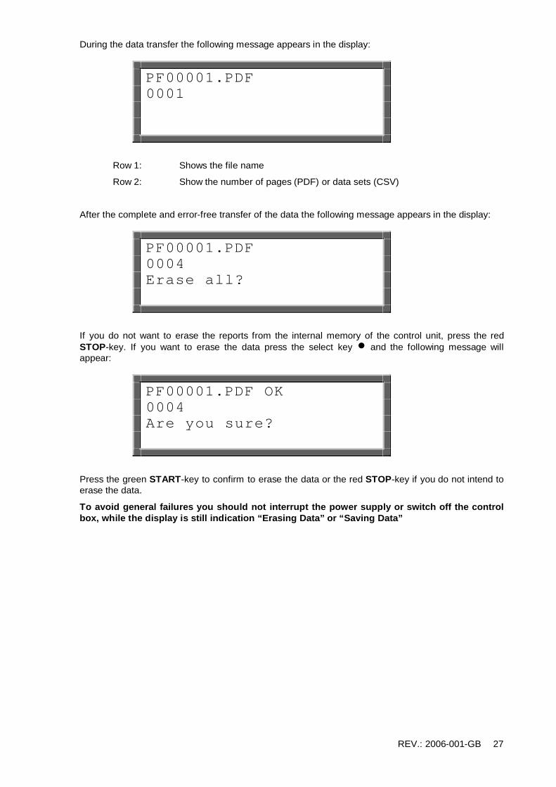
During the data transfer the following message appears in the display:
PF00001.PDF 0001
Row 1: Shows the file name
Row 2: Show the number of pages (PDF) or data sets (CSV)
After the complete and error-free transfer of the data the following message appears in the display:
PF00001.PDF 0004 Erase all?
If you do not want to erase the reports from the internal memory of the control unit, press the red STOP-key. If you want to erase the data press the select key n and the following message will appear:
PF00001.PDF OK 0004 Are you sure?
Press the green START-key to confirm to erase the data or the red STOP-key if you do not intend to erase the data.
To avoid general failures you should not interrupt the power supply or switch off the control box, while the display is still indication “Erasing Data” or “Saving Data”

REV.: 2006-001-GB 28
7.6.2 Error list (USB-Data transfer)
Warning: USB-memory stick are no safe place for permanent storing of data. Transfer the data as soon as possible to a desktop or notebook PC. And erase the files on the memory stick. The number of files of each file format is limited to a number of 30.
Error message Cause Reaction
NO USB SYSTEM USB – port system failure Control unit must be checked.
NO USB STICK The USB-memory stick in not plugged in correctly.
The USB-memory stick was not detected.
Plug in the USB-memory stick correctly.
Remove and re-plug the USB-memory stick
Use a different USB-memory stick.
USB FILENAME USB ERROR USB FILESYS DIR ERROR USB BLOCK
File/folder cannot be created.
Error when writing on the memory stick.
Remove write protection of the memory stick.
Retry data transfer.
Use a different USB-memory stick.
TOO MUCH FILES There are more than 30 files of on file format on the USB-memory stick.
Transfer some of the data to the PC or notebook and erase files for the memory stick.
ERROR SYSTEM USB1
Control unit error Retry data transfer.
Control unit must be checked eventually.
7.6.3 Erase reports
This function will erase the reports of a selected commission number. You will be prompted to enter a valid supervisor code to enter this function.
After choosing this function the last used commission number will appear in the display. Use the cursor keys v to scroll through the list of available commission numbers and press the green START-key to select the present number. The display will show “Erase ?”. Check first if the printout or data transfer was complete before confirming the erasing of the reports by pressing the select key n. For safety reasons the display will prompt again “Are you sure?” press the green START-key to confirm.
To avoid general failures you should not interrupt the power supply or switch off the control box, while the display is still indication “Erasing Data” or “Saving Data”
If you do not want to erase the reports, press the red STOP-key
REV.: 2006-001-GB 29
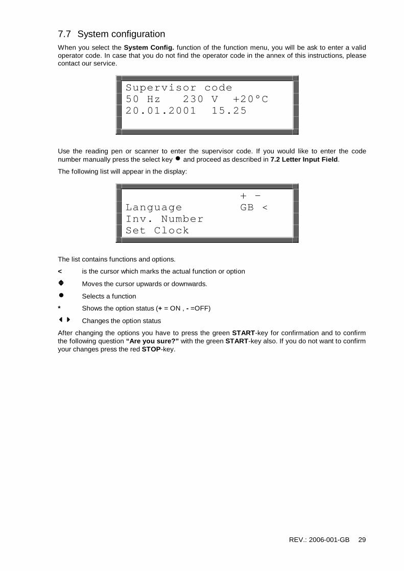
7.7 System configuration When you select the System Config. function of the function menu, you will be ask to enter a valid operator code. In case that you do not find the operator code in the annex of this instructions, please contact our service.
Supervisor code 50 Hz 230 V +20°C 20.01.2001 15.25
Use the reading pen or scanner to enter the supervisor code. If you would like to enter the code number manually press the select key n and proceed as described in 7.2 Letter Input Field.
The following list will appear in the display:
+ - Language GB < Inv. Number Set Clock
The list contains functions and options.
< is the cursor which marks the actual function or option
v Moves the cursor upwards or downwards.
n Selects a function
* Shows the option status (+ = ON , - =OFF)
34 Changes the option status
After changing the options you have to press the green START-key for confirmation and to confirm the following question “Are you sure?” with the green START-key also. If you do not want to confirm your changes press the red STOP-key.

REV.: 2006-001-GB 30
The following table shows the available functions and options:
Item Description Value Page
Language Function, which changes the display language Short code for Language
31
Inv. Number Function, which changes the Inventory Number 8 digit alphanumerical 32
Set clock Function, which changes the time 31
Daylight Time Daylight saving ON/OFF 32
Memory Control Memory Control ON/OFF 32
Weld Number Additional input of Joint Number ON/OFF 34
Weather Obligatory input of Weather Condition ON/OFF 34
Comm. No. Obligatory input of Comm.-No. ON/OFF 24
Worker Code Obligatory input of Worker Barcode ON/OFF 33
Welder Name Obligatory input of Worker Name ON/OFF 35
Traceability Code Obligatory Input of the traceability code of the fitting ON/OFF 35
Pipe Code Obligatory Input of the traceability code of the pipes ON/OFF 35
Pipe Length Obligatory Input of the pipe length ON/OFF 35
Trench Depth Obligatory Input of the trench depth ON/OFF 35
Cont. Numbers Continuous numbering of the welding reports ON/OFF -
South Option for configure daylight saving for southern hemisphere
ON/OFF -
Fusamatic Option for deactivating FUSAMATIC system ON/OFF -

REV.: 2006-001-GB 31
7.7.1 Change language
After selecting the language function from the system configuration menu the display will show a list of language indicators.
>GB SE ES
The indicators stand for: GB = English, SE = Swedish, ES = Spanish, IT= Italian, DK = Danish, PT = Portuguese, DE = German, FR = French, PL = Polish, TR = Turkish, RO = Romanian, etc. Please note that only 7 languages are available.
> Represents the cursor, which marks the present current language.
v Move the cursor upwards or downwards through the available languages.
n Selects the marked language
The display will ask you “Are you sure?”. You can confirm the correctness of your choice by pressing the green START-key or cancel the function by using the STOP-key.
7.7.2 Set clock
After selecting the set clock function from the system configuration menu the display will show current time and date:
20.01.2003 15.25
You always change the flashing or underlined digit.
v Will increase or decrease the respective value.
34 Move the marking to the digit you want to change.
n Finishes your changes.
The display will ask you “Are you sure?”. You can confirm the correctness of your choice by pressing the green START-key or cancel the function by using the STOP-key.

REV.: 2006-001-GB 32
7.7.3 Input of inventory number
After selecting the inventory number function from the system configuration menu the display will show the letter input field.
00000001 Inventory number ABCDEFGHIJKLMNOPQRST UVWXYZ0123456789 $-/
Enter your wanted inventory number referring to 7.2 Letter Input Field. Confirm the entered inventory number by pressing the green START-key.
The display will ask you “Are you sure?”. You can confirm the correctness of your choice by pressing the green START-key or cancel the function by using the STOP-key.
7.7.4 Daylight time Option
With this option you can enable the automatic change of daylight time for summer and winter time (ON). The enabled option causes that the request Set daylight time will appear in the display after turning on the device from the March 21st or October 21st. If you confirm this message by pressing the green START-key the clock will be set to the summer or winter time (±1hour). If you press the red STOP-key, the time changing will be rejected and the message will appear at the next turning on of the device again.
7.7.5 Memory control Option
If you have activated (ON) the memory control option, the device will refuse the any kind of welding process in the case that the internal memory is filled up. By this you can prevent a data loss. If the memory control is deactivated (OFF) the oldest stored reports will be overwritten.

REV.: 2006-001-GB 33
7.8 Request: Worker Code By switching on the worker code option of the system configuration you are demanded to enter worker identification barcode after switching on the control box. The following message demands the worker code:
Worker Code 50 Hz 230 V +20°C 20.01.2001 15.25
Use the scanner or reading pen to read in a present welder code. If the barcode is damaged you can enter the numerical code manually. Press the select key n to open the letter input field:
Worker code ABCDEFGHIJKLMNOPQRST UVWXYZ0123456789 $-/
The manual input of the welder code will be done by using the shown letter input field (ref.: 7.2 Letter Input Field). Confirm the entered welder code by pressing the green START-key.
Worker Codes can be conform ISO 12176-3 or manufacturer definition. The control box supports three levels of authorisation:
Worker Code: Allows the use of Barcode and Fusamatic mode.
Fore worker Code: Allows the use of Barcode, Manual and Fusamatic mode.
Supervisor Code: Allows the use of Barcode, Manual and Fusamatic mode and to enter the system configuration.
7.9 Request: Set daylight time This start up message after the March 21st or October 21st, if the daylight time option of the system configuration is switched on.
If you confirm this message by pressing the green START-key the clock will be set to the summer or winter time (±1hour). If you press the red STOP-key, the time changing will be rejected and the message will appear the next time you will turn on the device.

REV.: 2006-001-GB 34
7.10 Request: Weld Number By switching on the weld number option of the system configuration you are demanded to enter or confirm a weld number before each welding process.
The following message demands the weld number:
0001 Weld-Number ABCDEFGHIJKLMNOPQRST UVWXYZ0123456789 $-/
The display shows the present weld number, which will automatically increased after each weld. You can edit the shown number (ref.: 7.2 Letter Input Field). Confirm the entered weld number by pressing the green START-key.
7.11 Request: Weather condition By switching on the weather option of the system configuration you are demanded to enter the weather conditions and protection means. The following messages refer to the input of those:
Sunny < Dry Rain Windy
No < Shield Tent Heating
> Is the cursor for marking the active item
v Move the cursor upwards and downwards.
* Indicates a selected item
n Will select / deselect one item
Select all items which specified the current situation and confirm with the green START-key.

REV.: 2006-001-GB 35
7.12 Traceability System The following traceability functions are activated in the system configuration:
• Worker Code • Comm.-No. • Traceabilty Code (Fitting) • Pipecode 1 /2 • Pipelength • Trench Depth • Information
These functions are for the recoding of the pipe or components barcodes conform ISO12176-4. The data will be assigned to the welding report and its corresponding commission number. The functions will be shown in the workflow preparing a joint. Some additional function may be enabled or disabled.
Plug in the Controller and Switch on
PF Polymatic Plus Version 1.06aa 25 Working Hours 1200 Reports Free
Enter worker code
* Worker Code ABCDEFGHIJKLMNOPQRST UVWXYZ0123456789 $-/
- Read Barcode conform Manufacturer definition or ISO 12176-4.
- Optional: Input through letter input field
Connect Fitting
Connect Fitting ++++Comm.-No.++++ Report No. 7

REV.: 2006-001-GB 36
Obligatory input of Comm.-No.
Comm.-No. ++++Comm.-No.++++ 6
BARCODE Read in Job-No. Barcode START Take over displayed Comm.-No. v Page through Comm.-No. list n Enter Comm.-No. In letter input field
Enter welding barcode
Fitting Code 50Hz 230V +20°C 19.11.2003 15:25
Read fitting barcode
Enter Traceability Code (Fitting)
Traceability Code PF I d110
BARCODE Read in traceability barcode of the fitting START Steps over this function n Enter traceability code in letter input field STOP back to Comm.-Nr. Input
Enter Pipe Code 1
1. Pipe Code
BARCODE read in traceability barcode of the 1st pipe START step over this function

REV.: 2006-001-GB 37
n Enter traceability code in letter input field STOP step back to last function
Enter Pipe Length of Pipe 1
1.Pipe Pipe Length 012.00m
v change value of marked digit. 34 move cursor to next digit START take given value STOP step back to last function
Enter Pipe Code 2
2. Pipe Code
BARCODE read in traceability barcode of the 1st pipe START step over this function n Enter traceability code in letter input field STOP step back to last function
Enter Pipe Length of Pipe 2
2.Pipe Pipe Length 012.00m
v change value of marked digit. 34 move cursor to next digit START take given value STOP step back to last function

REV.: 2006-001-GB 38
Enter Trench Depth
Trench Depth 012.00m
v change value of marked digit. 34 move cursor to next digit START take given value STOP step back to last function
Start welding process
Start Nom. Time : 200s PF I d110 +25°C
START start welding process n enter additional information (letter input field) STOP step back to last function

REV.: 2006-001-GB 39
8 Trouble shooting
8.1 Using and replacing the reading pen Using the reading pen:
Place the tip of the reading pen left or right beside the bar code. Move the reading pen with a constant speed over the whole barcode. Do not stop the movement or lift the reading pen off.
Replacing reading pen (Order Code: 1_0100_001) :
If the reading pen does not works properly you can replace it on your own. Slit open the shirk tube which protects the plug with a sharp knife. Pay attention on the cables. Replace the reading pen and test it before you mount the new shirk tube.
8.2 Replacing Welding Terminals
The welding plugs should be checked frequently. If necessary they can easily replace in no time.
1. Switch off the device and disconnect it from the mains supply or generator!
2. Slip off the PVC-cap over the welding terminal.
3. Hold the front part of the brass contact with a pipe wrench and screw the welding terminal with a 8mm-wrench out of the brass contact.
4. The red welding cable has to be equipped by a welding terminal with detection tip! You have to use welding terminals that are delivered by PF only!
5. Screw the new welding terminal tight into the brass contact and slip the PVC-cap over the welding terminal. Pay attention, that the PVC-cap is slipped over so far, that the welding terminal is left blank for about 15mm.
1_0200_001 Welding Terminal 4.7mm, standard 1_0200_003 Welding Terminal 4.0mm, standard 2_0200_003 Welding Terminal 4.7mm, Fusamatic (with detection tip) 2_0200_004 Welding Terminal 4.0mm, Fusamatic (with detection tip) 1_0410_004 PVC-Cap, red 1_0410_003 PVC-Cap, black
8.3 Adapter For different fitting types different adapters are needed. In the following table you will find a selection of available adapters:
1_0300_009 Adapter 4.7/4.7 angle 1_0300_001 Adapter 4.7/4.0 angle 1_0300_004 Adapter 4.0/4.7 angle 1_0300_011 Adapter 4.0/4.0 angle 1_0200_005 FUSAMATIC-Adapter 4.7/4.7 1_0200_006 FUSAMATIC-Adapter 4.7/4.0 1_0200_007 FUSAMATIC-Adapter 4.0/4.7 1_0300_010 Adapter 4.0/4.7, straight 1_0300_003 Adapter 4.7/GF (lose ends) 1_0300_014 Adapter 4.0/GF (lose ends) 1_0300_002 Adapter 4.7/FF-flat 1_0300_012 Adapter 4.0/FF-flat 1_0300_008 Adapter 4.7/FF-pin 1_0300_013 Adapter 4.0/FF-pin

REV.: 2006-001-GB 40
8.4 Start messages After switching on the device the following message appears on the display:
PF polymatic Plus Version 2.04AH 25 Working hours 1000 Reports free
Row 1 and 2 show the type and firmware revision of the control box.
Row 3 counts the total amount of working hours (summed up fusion times).
Row 4 indicated the total number of free reports of the data recording system. In the case that the amount of free reports is smaller than 50, the letters of this row will flash. Press the red STOP-key to confirm the rare memory space. The reports should be printed out, because there is the danger of data loss if the memory control option is deactivated.
After ten seconds the above shown display will disappear.
In the following there could be shown system messages like error messages of previous welding cycles or service notes, which can be aborted by pressing the red STOP-key.

REV.: 2006-001-GB 41
8.5 Error messages Error messages will be indicated by a bleep. A permanent bleep can be interrupted by pressing the red STOP-key.
Error Cause Reaction
Clock error Internal clock does not work properly. Set clock. Maybe the battery has to be changed.
Code error Faulty input. Move the reading pen with a constant velocity over the barcode.
Barcode defect or error of code structure.
Contact error Invalid FUSAMATIC©-detection-resistor.
Clean contacts. Replace fitting if necessary.
Current high Output current is more than 15% higher than the starting current.
Shortcut of fitting coil or welding cable.
Current low Interrupt of the welding current. Welding is faulty!
Current drops down about 15-20% for at least 3s.
Welding is faulty!
Device too hot Temperature of transformer is too high
Let the device cool down for about 45 min.
Emergency cut-out Welding was interrupted by pressing the STOP-key.
Welding is faulty!
Frequency error Input frequency out of working range (40-70Hz).
Check Generator.
Input voltage high Input voltage >300V at 230V nom. Input voltage >150V at 110V nom.
Adjust generator voltage to 240V-260V. Adjust generator voltage to 120V-130V.
Input voltage low Input voltage < 190V at 230V nom. Input voltage < 90V at 110V nom.
Unwind the power supply cable. Use power supply cable with the right diameter. Adjust Generator voltage.
Interturn shortc. The current rises more than 15% during the welding. Shortcut of the fitting coil.
Welding is faulty!
Memory overflow Report memory is full up. Print reports or deactivate the memory control option.
No contact No complete electrical contact with the fitting.
Check connection to the fitting.
Fitting coil or welding cable is defect. Use an other Fitting. Change welding cable.
Output volt. Error The output voltage deviates from the Check the generator.

REV.: 2006-001-GB 42
rated voltage. Revolutions fluctuate or power too weak.
Power failure Last welding was interrupted by a break of the power supply.
Last welding is faulty! Prepare pipe again and use a new Fitting!
Resistor error Fitting resistance is out of the valid working range.
Clean the contacts. Use an other fitting.
Fitting resistance out of the valid range given by barcode.
Clean the contacts Use an other fitting.
Service The recommended service interval of 12 months or 200 working hours is exceeded.
The device has to be checked by an authorized service point. The device is still usable, but the manufacturer does not accept any liability for the device until it is checked up.
System error Danger! Selftest found an error in the system.
Disconnect power supply immediately. Do not connect the device to the power supply any more. Send it to the next service point.
Temp. Meas. Error Temperature measurement is faulty. Plug in the removable welding cable. Switch device off and on. Welding cable or sensor defect.
Temperature error Surrounding temperature out of working range (-10-+50°C).
9 Supervisor Code
4 8 5 2 9 9 9 9 0 3 0 3 9 9 9 1 1 0 0 8

REV.: 2006-001-GB 43
10 Alphanumeric code table
A B C A B C
D E F D E F
G H I G H I
J K L J K L
M N O M N O
P Q R P Q R
S T S T

REV.: 2006-001-GB 44
U V W U V W
X Y Z X Y Z
/ 1 Space / 1
2 3 4 2 3 4
5 6 7 5 6 7
8 9 0 8 9 0
$ -
$ -

REV.: 2006-001-GB 45
11 Conformity Declaration

REV.: 2006-001-GB 46