polyhedral modularity in a special class of decagram based...
TRANSCRIPT

Polyhedral Modularity in a Special Class of Decagram Based
Interlocking Star Polygons
Reza Sarhangi
Department of Mathematics
Towson University
Towson, Maryland 21252, USA
Abstract
The main effort in this article is to study a series of Persian mosaic designs that have been illustrated in scrolls or which
decorate the surfaces of old structures. The common element in these designs is a special ten pointed star polygon.
This special concave polygon, called a decagram for convenience, is the dominant geometric shape of a series of
polyhedral tessellations that all consist of the same common motifs.
1. Introduction
From a few documents left from the past, it is evident that the designers of patterns on the surfaces of
medieval structures in Persia and surrounding regions, were well-equipped with a significant level of
knowledge of applied geometry. Nevertheless, none of them exhibits the same level of effort or interest
in providing the pure side of the subject by proving theorems and establishing mathematical facts about
such designs. The main concern of a designer or a craftsman was to present a visual harmony and
balance, not only in deep details, but also as a whole. But the steps taken for creating such designs, which
can be discovered today give little room to a researcher to assume accident or pure experience. Some
techniques are only acquired and understood by mathematicians. An individual with the knowledge of
such detailed techniques is a mathematician, artist or not.
2. Tiling with a Special Ten Pointed Star Polygon (decagram)
Figure 1 exhibits a method for creating a tiling design [4]. In this method, the starting point is a (10, 3)
Star Polygon – a figure created from connecting every third vertex in a set of 10 equally spaced points on
a circle in one direction in one stroke (the star inside the circle on the upper left corner of Figure 1). By
extending some of the segments that constituted the (10, 3) Star Polygon and intersecting them with the
Figure 1: (U) The compass-
straightedge construction of a
decagram tile (LL) The
tessellation of the tile, (LR) The
tessellation of the pattern on an
existing wall in Masjid-i-Jami,
Kerman in Iran.
Bridges 2012: Mathematics, Music, Art, Architecture, Culture
165

lines perpendicular to some other segments, one achieves the construction of the rectangular frame and
other necessary line segments inside the frame as is on the upper right corner of Figure 1. This
rectangular tile tessellates the plane and creates a pleasing series of stars that are ordered in columns and
in rows.
In the tessellation presented in Figure 1, the special ten pointed star polygon, which is the dominant
geometric shape of the tessellation, can be created independently through the rotation of two concentric
congruent regular pentagons with a radial distance of 36° from each others’ central angles (Figure 2(a,
b)). Such a rotation with a radial distance of 45° for two squares creates the attractive and
overwhelmingly used 8 pointed star polygon (call it octagram) that has appeared in many geometric
designs and tilings as cross-octagram tessellations in Persian architecture and around the world (Figure
2(c, d, e)). So we may assume that creating a tile design using this 10-pointed star polygon (call it a
decagram for convenience) was a challenge for designers, compared to a not-so-complicated and straight
forward cross-octagram tessellation that can be defined in a square-shaped frame.
Figure 2: (a) Two concentric pentagons, (b) generated decagram, (c) two concentric squares, (d)
generated octagram, (e) a tile for the cross-octagram tessellation.
Studying documents from the past reveals that in most cases the fundamental regions, similar to what is
shown in Figure 1.UR, were shapes stored in scrolls (tumār) and booklets (daftar) as designs used in the
executions of the actual tiling on the surfaces or as geometric experimentations of interlocking star-
polygon patterns. Such a fundamental region was called a knot (girih) in Persian architecture.
Figure 3: (L) Imamzeda
Darbi Islam, Isfahan in
Iran, (R) The five Sâzeh
module tiles.
The existing tessellation on the wall of a Persian structure in Figure 3.L includes a decagram motif. There
are other shape tiles that constitute the tiling. In fact there are exactly five motifs (modules). Figure 3.R
presents these modules. They are called Muarraq (معرق), an Arabic word, in Iran. The Arabian-
Andalusian word for these hand-cut pieces of glazed ceramic tiles is Zellij. In this script they are called
Sâzeh module tiles (سازه, structure in Persian).
(e)(d)(c)(b)(a)
Sarhangi
166

These modules have their own specific Persian names: Torange (the quadrilateral tile), Pange (the
pentagonal tile), Shesh Band (the concave octagonal tile), Sormeh Dân (the bow tie tile), and Tabl
(decagram tile).
Comparing the two tessellations in Figures 1 and 3, one may notice that, despite the fact that the
individual Sâzeh modules used in both tessellations are identical, they are very different tessellations.
The following solution for the geometric construction of the tiling in Figure 3, with some revisions in the
process, comes from the professional artisan, Maheronnaqsh, who inherited his profession from his
ancestors of several centuries, who had the most access to original artisans’ repertories of the past [12]:
Divide the right angle A into five congruent angles by creating four rays that emanate from A. Choose
an arbitrary point C on the second ray, counter-clockwise, and drop perpendiculars from C to the sides of
angle A. This results in the rectangle ABCD along with four segments inside this rectangle, each with
one endpoint at A and whose other endpoints are the intersections of the four rays with the two sides of
CB and CD of rectangle ABCD. Find E, the midpoint of the fourth segment created from the fourth ray.
Construct an arc with center A and radius AE to meet AB on F and the second ray on G (the second
segment is now part of the diagonal of the rectangle). Make a line, parallel to AD, passing through G, that
intersects the first ray at H and the third ray at I. Line FH passes through point E and meets AD at J.
Construct a line, passing through J, that parallels the third ray. Also construct line EI. From F make a
parallel line to the third ray to meet the first ray at K. Construct segments GK, GL, and EM. Find N such
a way that GI = IN. Make a line through N, parallel to GK, to intersect the line emanate from J, to find P
to complete the regular pentagon EINPJ. Line DN meets the perpendicular bisector of AB at Q. From Q
construct a line parallel to FK to intersect ray MI at R and then complete the figure (Figure 4.L).
Figure 4
Using O, the center of the rectangle ABCD, as a center of rotation for 180°, one can make the
fundamental region for the tiling in Figure 3. The last two images in Figure 4 show a tile and its
tessellation, which is the tiling design in Figure 3.
Figure 5
Polyhedral Modularity in a Special Class of Decagram Based Interlocking Star Polygons
167
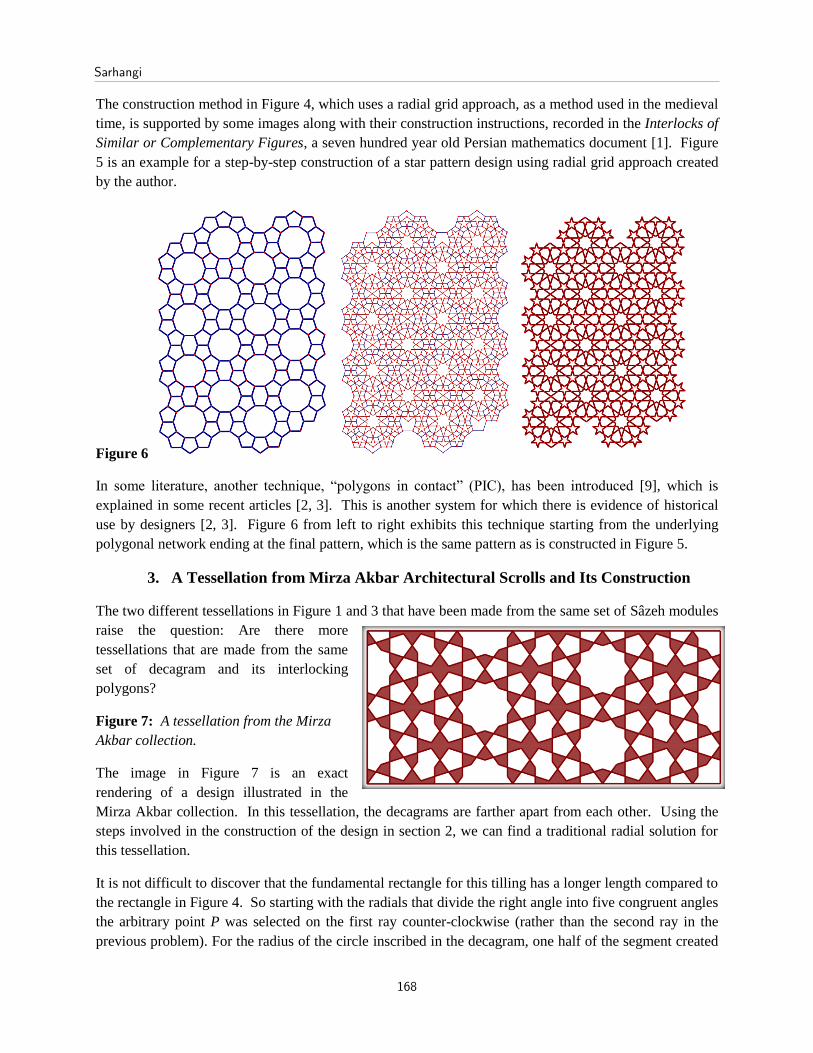
The construction method in Figure 4, which uses a radial grid approach, as a method used in the medieval
time, is supported by some images along with their construction instructions, recorded in the Interlocks of
Similar or Complementary Figures, a seven hundred year old Persian mathematics document [1]. Figure
5 is an example for a step-by-step construction of a star pattern design using radial grid approach created
by the author.
Figure 6
In some literature, another technique, “polygons in contact” (PIC), has been introduced [9], which is
explained in some recent articles [2, 3]. This is another system for which there is evidence of historical
use by designers [2, 3]. Figure 6 from left to right exhibits this technique starting from the underlying
polygonal network ending at the final pattern, which is the same pattern as is constructed in Figure 5.
3. A Tessellation from Mirza Akbar Architectural Scrolls and Its Construction
The two different tessellations in Figure 1 and 3 that have been made from the same set of Sâzeh modules
raise the question: Are there more
tessellations that are made from the same
set of decagram and its interlocking
polygons?
Figure 7: A tessellation from the Mirza
Akbar collection.
The image in Figure 7 is an exact
rendering of a design illustrated in the
Mirza Akbar collection. In this tessellation, the decagrams are farther apart from each other. Using the
steps involved in the construction of the design in section 2, we can find a traditional radial solution for
this tessellation.
It is not difficult to discover that the fundamental rectangle for this tilling has a longer length compared to
the rectangle in Figure 4. So starting with the radials that divide the right angle into five congruent angles
the arbitrary point P was selected on the first ray counter-clockwise (rather than the second ray in the
previous problem). For the radius of the circle inscribed in the decagram, one half of the segment created
Sarhangi
168

from the third ray, segment AM, was selected. Then a similar approach was taken to create the tiling in
Figure 7. Figure 8 illustrates a step-by-step visual solution to the problem.
Figure 8
4. A Square Girih for Constructing a Tessellation
Locating an arbitrary point on any of the rays that divide the right angle into five congruent angles and
dropping perpendiculars to the sides of the right angle results in only two different rectangles:
I. Selecting the arbitrary point C on the first ray and dropping the two perpendiculars BC and
CD to the sides of right angle A results in the rectangle ABCD (Figure 12.L), where the
relationship between its diagonal AC and side BC is AC/BC = 2 = 1+5, where is the
Golden Ratio. Therefore, AB/BC = .
II. Selecting the arbitrary point F on the second ray will result in the rectangle AEFG (Figure
12.L), which is the Golden Rectangle: AE/EF = .
Figure 9
Now the question is whether
using the same technique as
mentioned above, are we able to
come up with a new pattern
composed from all five Sâzeh
modules in Figure 3.R?
An interesting problem would be to consider the square as the girih solution. Obviously, none of the rays
that divide A into five congruent angles helps directly. Choosing P as an arbitrary point on the angle
bisector of A and constructing square AHPK cannot help us either (Figure 9.R) . Nevertheless, we are
able to obtain a solution, if we start with an arc, with center A, and an arbitrary radius. This arc cuts the
rays in certain points that are used to find a solution. The following images in Figure 10, starting from
the upper left and ending at the lower right, demonstrate a step-by-step solution to this problem by the
author.
Figure 11 is a tessellation that is created from the five Sâzeh modules based on the square girih in Figure
10. This artwork was exhibited in the Joint AMS-MAA Mathematics Meeting in Boston, Massachusetts,
USA, in January 2012 [5] and in the 2012 Bridges Mathematical Art Exhibition at Towson University,
Maryland.
Polyhedral Modularity in a Special Class of Decagram Based Interlocking Star Polygons
169

Adding the tiling in Figure 11 to the above three tilings, illustrated in figures 1, 4, and 7, makes a set of
four different mosaic patterns, each made from the aforementioned five Sâzeh modules. A curious reader
may want to know whether more tessellations can be formed from this set of modules. The same
curiosity may have promoted the craftsmen-mathematician of the past to look for new solutions that are
not necessarily, at least in part, based on the compass-straightedge constructions.
Figure 10 Figure 11
5. Modularity Approach in Mosaic Designs
5.1. Modularity based on color contrast: Figure 12 Kharragan I (January 2011) is an artwork by the
author based on a design on one of the 11th century twin tomb towers in Kharraqan, western Iran. The
artwork demonstrates two different approaches that are assumed to have been utilized centuries ago to
create the layout of the pattern, which is at the
center of the artwork. From left to right, the
artwork exhibits the construction of the design
based on a compass and straightedge. From
right to left, we see another approach, the
Modularity method based on color contrast, to
construct the same design using cutting and
pasting of tiles in two colors. These two
methods of constructions were presented at
[16] Figure 12
5.2. Modularity based on motifs formed from the combination of polygons. Figure 13.M, Hope
(December 2008) is an artwork by the author [7], which is based on the modularity concept using two
triangles that each have been composed from smaller triangles and rhombuses in three colors. The actual
tiling adorns a wall of Bibi Zinab Mausoleum in Isfahan, Iran. Notice that in Figure 13.L, except for the
corners, the two compound triangles (girih modules) are in opposite colors. Using these two girih
modules in a rotational fashion, results in the pattern in this artwork (Figure 13.M). To make an actual
tiling for this pattern a craftsman may use the cut Sâzeh tiles that are presented in Figure 13.R.
Sarhangi
170

Figure 13: (L) The two modules used to find
the layout of a tessellation, (M) “Hope”
(December 2008), and (R) The sâzeh tiles that
were used to create this pattern.
Figure 14
6.qModularity in Interlocking Star Polygon Mosaic Designs
Jay Bonner explained the polygonal system, polygons in contact, which was used in the creation of the
patterns in the past (see Figure 6) [2]. Figure 14 illustrates the ten polygons that form the five-fold
system. In this method, a craftsman makes an underlying polygonal matrix that is generated from
modules in Figure 14 (Figure 6.L). Then he uses the midpoints of the polygons to discover new lines that
form a new tiling pattern (Figure 6.M). When the process of creation is complete, then the initial
polygonal matrix is discarded (Figure 6.R).
Looking at Figure 15 (Darb Imam, Isfahan) Bonner noticed a set
of lines that connect the centers of decagrams to form another
tessellation with larger composite tiles (these lines have been
made bold to be more visible). He used this figure in his
treatment of Self-Similarity in the Medieval Persian mosaic
design.
Figure 15
An informative book that appeared in recent years about mosaic design and its history is The Topkapi
Scroll [14]. The book includes all the images on the Topkapi Scroll. The scroll presents 114 images for
creating designs. Bonner used the Topkapi Scroll: No. 28 image (Figure 16.L) as another example for the
5-fold Self-Similar Type A: “Pattern 28 in the Topkapi scroll is a 5-fold self-similar Type A design that
also depicts the underlying polygonal sub-grid used in the creation of the secondary design…. That this
very particular technique was used historically is conformed in the Topkapi scroll. Pattern 28 from this
scroll makes use of small red dots to distinguish the underlying polygonal sub-grid of the secondary
pattern.” [2]
Lu and Steinhardt also noticed these red dotted lines. They proposed that these dotted lines exhibit a new
set of tiles, where the black solid lines determine the design on each of these new tiles [11]. They realized
that this new set can be used as a set of modules, similar to the modules that were presented in the
previous section, but now in more complex forms, for finding new interlocking star polygon patterns.
This eliminates the hardship involved in a compass-straightedge construction and, in fact, opens the door
Polyhedral Modularity in a Special Class of Decagram Based Interlocking Star Polygons
171
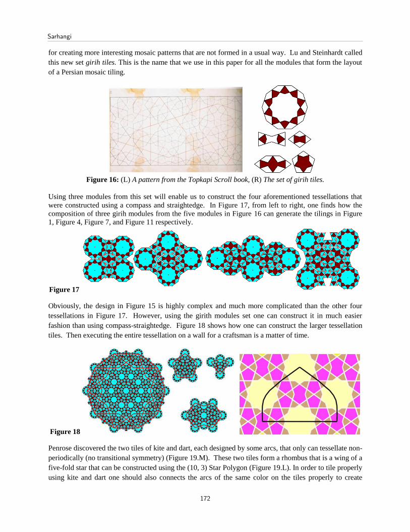
for creating more interesting mosaic patterns that are not formed in a usual way. Lu and Steinhardt called
this new set girih tiles. This is the name that we use in this paper for all the modules that form the layout
of a Persian mosaic tiling.
Figure 16: (L) A pattern from the Topkapi Scroll book, (R) The set of girih tiles.
Using three modules from this set will enable us to construct the four aforementioned tessellations that
were constructed using a compass and straightedge. In Figure 17, from left to right, one finds how the
composition of three girih modules from the five modules in Figure 16 can generate the tilings in Figure
1, Figure 4, Figure 7, and Figure 11 respectively.
Figure 17
Obviously, the design in Figure 15 is highly complex and much more complicated than the other four
tessellations in Figure 17. However, using the girith modules set one can construct it in much easier
fashion than using compass-straightedge. Figure 18 shows how one can construct the larger tessellation
tiles. Then executing the entire tessellation on a wall for a craftsman is a matter of time.
Figure 18
Penrose discovered the two tiles of kite and dart, each designed by some arcs, that only can tessellate non-
periodically (no transitional symmetry) (Figure 19.M). These two tiles form a rhombus that is a wing of a
five-fold star that can be constructed using the (10, 3) Star Polygon (Figure 19.L). In order to tile properly
using kite and dart one should also connects the arcs of the same color on the tiles properly to create
Sarhangi
172

continuous curves (closed or open). Based on a set of compounded tiles created by John Conway [8], Lu
and Steinhardt proposed three new tiles that resemble three of girih tiles and generates Penrose tilings
(Figure 19.R).
Figure 19
Using this new set in Figure
19.R and replacing them with
the girih tiles of Figure 16. R
Lu and Steinhardt suggested a
possible quasi-periodicity
structures in some Persian
tilings. Similar quasi-periodic
patterns were noticed and
analyzed by Makovicky [13] a
few years earlier. Moreover,
Rigby [15] discovered a way to cover the surface of kites and darts with appropriate Sâzeh tiles to
generate various non-periodic interlocking patterns. Nevertheless, the discovery of the girih tiles in
Figure 16 was without doubt a remarkable point in the study of mosaic designs.
Note that by using the tiles suggested by Rigby one can make the three girih modules in a way that the
tiles tessellate the plane non-periodically (Figure 20).
Figure 20
Looking at similar designs as in Figure 16 one may come to this conclusion that the designers of the past
were looking for maximum symmetries, especially local and global rotational symmetry, especially 5-fold
and 10-fold rotational symmetries, than anything else. So some of their mosaic designs have attracted the
modern crystallography researchers, who have found similar patterns.
It is important to note that the Penrose tiles cannot produce a global or local 10-fold rotational symmetry.
They only can form 5-fold symmetries. There are uncountably many Penrose tilings. None of them have
global 5-fold rotational symmetry but two. The two tessellations that have global 5-fold rotational
symmetry are called “Sun” and “Star”. Figure21. L is the Sun tessellation. Figure 21.R is the same
tessellation covering with the Rigby tiles. The central circular part of the tessellation in Figure 21.R,
which includes the first series of decagrams that are equidistance from the center, resembles the
decagonal girih tile in Figure 18 L. Nevertheless, a bigger portion of this Sun only holds 5-fold rotational
symmetry but the decagon in Figure 18L has 10-fold rotational symmetry.
Polyhedral Modularity in a Special Class of Decagram Based Interlocking Star Polygons
173

Figure 21: Penrose Sun and the Girih Sun
References
[1] Anonymous. Interlocks of Similar or Complementary Figures. Paris: Biblioth`eque Nationale, ancien fonds.
Persan 169, ff. 180r–199v.
[2] Bonner, J., Three traditions of self-similarity in fourteenth and fifteenth century Islamic geometric ornament,
Proceedings of the ISMA/Bridges: Mathematical Connections in Art, Music, and Science, R. Sarhangi and N.
Friedman, eds, Granada, Spain, 2003, pp. 1-12.
[3] Cromwell, P.R., The search for quasi-periodicity in Islamic 5-fold ornament, Math. Intelligencer 31, 2009, pp.
36 – 56.
[4] El-Said I. and A. Parman, Geometric Concepts in Islamic Art, World of Islam Festival Publishing Company,
London, 1976.
[5] Fathauer R. and Nathan S Nathan Selikoff, eds, Joint Mathematics Meeting Art Exhibition Catalog 2012,
Boston.
[6] Fathauer R. and Nathan S Nathan Selikoff, eds, Bridges International Conference Art Exhibition Catalog 2011,
Coimbra, Portugal.
[7] Fathauer R. and Aklaman E., eds, Bridges Art Exhibition Catalog 2009, Banff, Canada.
[8] Gardner, M. Pentose Tiles to Trapdoor Ciphers, MAA, 1977
[9] Hankin, E.H., The Drawing of Geometric Patterns in Saracenic Art, Memories of the Archaeological Society of
India, Vol. 15, Government of India, Calcutta, 1925.
[10] Kaplan, C.S., Islamic star patterns from polygons in contact, Graphics Interface 2005, ACM International
Conference Proceedings Series 112, 2005, pp. 177-186.
[11] Lu, P.J. and P.J. Steinhardt, Decagonal and quasi-crystalline tilings in medieval Islamic architecture, Science
315, 2007, pp. 1106 – 1110.
[12] Maheronnaqsh, M., Design and Execution in Persian Ceramics, Reza Abbasi Museum Press, Tehran,1984.
[13] Makovicky, E., In Five Fold Symmetry, I. Hargittali, ed, Word Scientific, Singapour, 1992, pp. 67-86.
[14] Necipoğlu, G., The Topkapi Scroll: Geometry and Ornament in Islamic Architecture, Getty Center Publication,
Santa Monica, USA, 1995.
[15] Rigby, J., Creating Penrose-type Islamic Interlacing Patterns, Bridges International Conference Proceedings,
Reza Sarhangi and John Sharp, eds, London, UK, 2006, pp. 41-48.
[16] Sarhangi, R., S. Jablan, and R. Sazdanovic, Modularity in Medieval Persian Mosaics: Textual, Empirical,
Analytical, and Theoretical Considerations, Bridges International Conference Proceedings, R. Sarhangi, ed,
Winfield, Kansas, 2004, pp. 281-292.
Sarhangi
174