pololu - sample project: simple hexapod walker · parts you will need to build the hexapod robot....
TRANSCRIPT
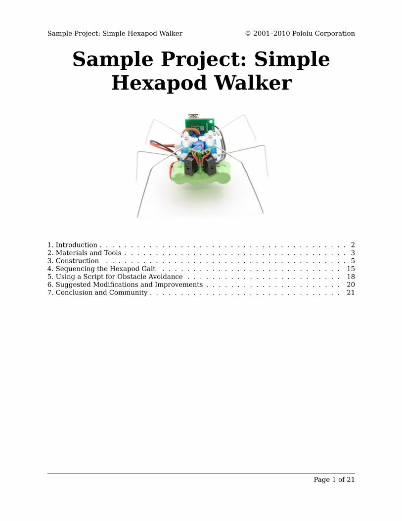
Sample Project: SimpleHexapod Walker
1. Introduction . . . . . . . . . . . . . . . . . . . . . . . . . . . . . . . . . . . . . . . . 22. Materials and Tools . . . . . . . . . . . . . . . . . . . . . . . . . . . . . . . . . . . . 33. Construction . . . . . . . . . . . . . . . . . . . . . . . . . . . . . . . . . . . . . . . 54. Sequencing the Hexapod Gait . . . . . . . . . . . . . . . . . . . . . . . . . . . . . 155. Using a Script for Obstacle Avoidance . . . . . . . . . . . . . . . . . . . . . . . . . 186. Suggested Modifications and Improvements . . . . . . . . . . . . . . . . . . . . . . 207. Conclusion and Community . . . . . . . . . . . . . . . . . . . . . . . . . . . . . . . 21
Sample Project: Simple Hexapod Walker © 2001–2010 Pololu Corporation
Page 1 of 21
1. IntroductionSix-legged locomotion is a simple, robust system of walking that is very popular both inthe animal kingdom and among robotics hobbyists. Robot hexapods range from simple one-motor toys to advanced platforms with 18 or more servos. This tutorial shows you how tobuild a very simple autonomous hexapod robot using just three servos. The 2"-high hexapodis capable of walking forward and backward, and can turn left and right. Two forward-looking distance sensors provide obstacle avoidance. The brain of the hexapod is the PololuMicro Maestro [http://www.pololu.com/catalog/product/1351], a 6-servo controller that can readinputs and play motion sequences in a stored script.
See the Micro Maestro User’s Guide [http://www.pololu.com/docs/0J40] for completedocumentation on the Micro Maestro.
Sample Project: Simple Hexapod Walker © 2001–2010 Pololu Corporation
1. Introduction Page 2 of 21
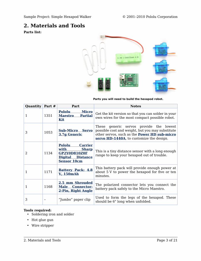
Parts you will need to build the hexapod robot.
2. Materials and ToolsParts list:
Quantity Part # Part Notes
1 1351Pololu MicroMaestro PartialKit
Get the kit version so that you can solder in yourown wires for the most compact possible robot.
3 1053 Sub-Micro Servo3.7g Generic
These generic servos provide the lowestpossible cost and weight, but you may substituteother servos, such as the Power HD sub-microservo HD-1440A, to customize the design.
2 1134
Pololu Carrierwith SharpGP2Y0D810Z0FDigital DistanceSensor 10cm
This is a tiny distance sensor with a long enoughrange to keep your hexapod out of trouble.
1 1171 Battery Pack: 4.8V, 150mAh
This battery pack will provide enough power atabout 5 V to power the hexapod for five or tenminutes.
1 11682.5 mm ShroudedMale Connector:2-Pin, Right Angle
The polarized connector lets you connect thebattery pack safely to the Micro Maestro.
3 – “Jumbo” paper clip Used to form the legs of the hexapod. Theseshould be 6" long when unfolded.
Tools required:• Soldering iron and solder• Hot glue gun• Wire stripper
Sample Project: Simple Hexapod Walker © 2001–2010 Pololu Corporation
2. Materials and Tools Page 3 of 21
• Long-nose pliers• Diagonal cutter• Some wire for connecting the parts
Most of these parts are available in the Tools [http://www.pololu.com/catalog/category/5] sectionof the Pololu web site. A hot glue gun is available at most craft stores for a few dollars.
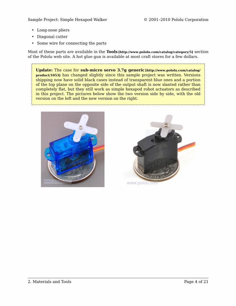
Update: The case for sub-micro servo 3.7g generic [http://www.pololu.com/catalog/product/1053] has changed slightly since this sample project was written. Versionsshipping now have solid black cases instead of transparent blue ones and a portionof the top plane on the opposite side of the output shaft is now slanted rather thancompletely flat, but they still work as simple hexapod robot actuators as describedin this project. The pictures below show the two version side by side, with the oldversion on the left and the new version on the right.
Sample Project: Simple Hexapod Walker © 2001–2010 Pololu Corporation
2. Materials and Tools Page 4 of 21
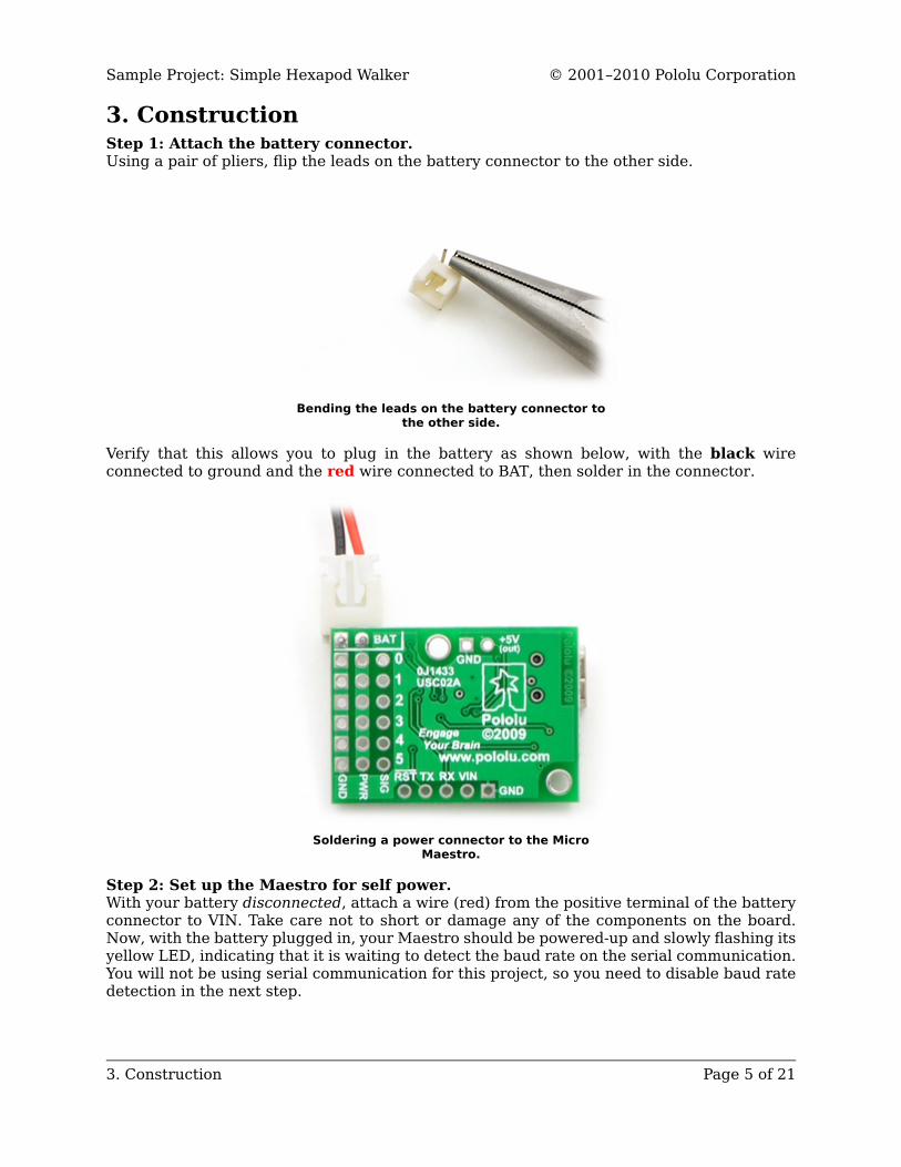
3. ConstructionStep 1: Attach the battery connector.Using a pair of pliers, flip the leads on the battery connector to the other side.
Bending the leads on the battery connector tothe other side.
Verify that this allows you to plug in the battery as shown below, with the black wireconnected to ground and the red wire connected to BAT, then solder in the connector.
Soldering a power connector to the MicroMaestro.
Step 2: Set up the Maestro for self power.With your battery disconnected, attach a wire (red) from the positive terminal of the batteryconnector to VIN. Take care not to short or damage any of the components on the board.Now, with the battery plugged in, your Maestro should be powered-up and slowly flashing itsyellow LED, indicating that it is waiting to detect the baud rate on the serial communication.You will not be using serial communication for this project, so you need to disable baud ratedetection in the next step.
Sample Project: Simple Hexapod Walker © 2001–2010 Pololu Corporation
3. Construction Page 5 of 21
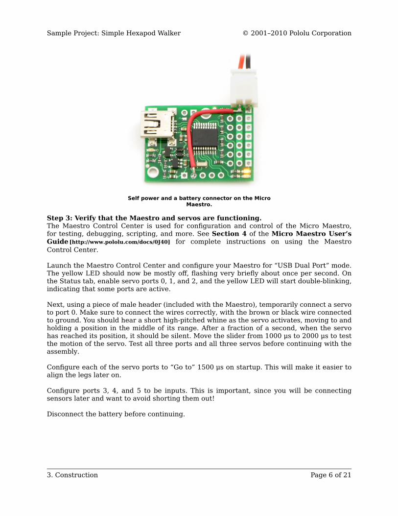
Self power and a battery connector on the MicroMaestro.
Step 3: Verify that the Maestro and servos are functioning.The Maestro Control Center is used for configuration and control of the Micro Maestro,for testing, debugging, scripting, and more. See Section 4 of the Micro Maestro User’sGuide [http://www.pololu.com/docs/0J40] for complete instructions on using the MaestroControl Center.
Launch the Maestro Control Center and configure your Maestro for “USB Dual Port” mode.The yellow LED should now be mostly off, flashing very briefly about once per second. Onthe Status tab, enable servo ports 0, 1, and 2, and the yellow LED will start double-blinking,indicating that some ports are active.
Next, using a piece of male header (included with the Maestro), temporarily connect a servoto port 0. Make sure to connect the wires correctly, with the brown or black wire connectedto ground. You should hear a short high-pitched whine as the servo activates, moving to andholding a position in the middle of its range. After a fraction of a second, when the servohas reached its position, it should be silent. Move the slider from 1000 μs to 2000 μs to testthe motion of the servo. Test all three ports and all three servos before continuing with theassembly.
Configure each of the servo ports to “Go to” 1500 μs on startup. This will make it easier toalign the legs later on.
Configure ports 3, 4, and 5 to be inputs. This is important, since you will be connectingsensors later and want to avoid shorting them out!
Disconnect the battery before continuing.
Sample Project: Simple Hexapod Walker © 2001–2010 Pololu Corporation
3. Construction Page 6 of 21
A sub-micro servo with mountingtabs clipped off.
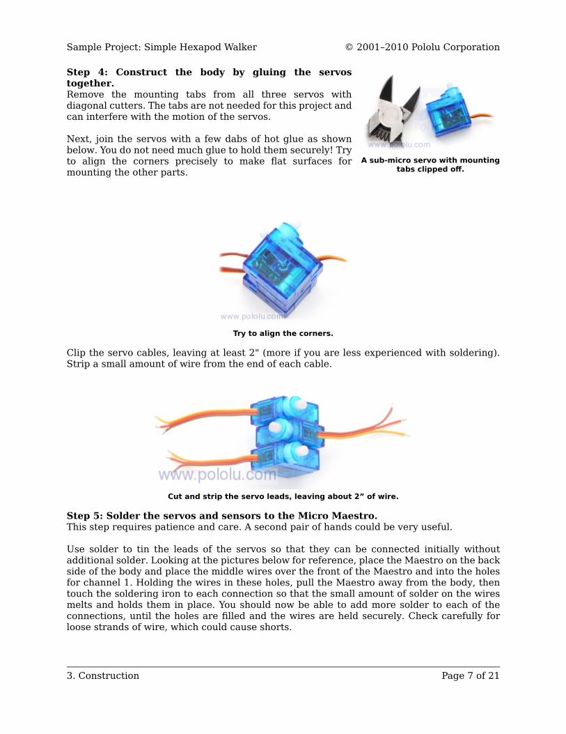
Step 4: Construct the body by gluing the servostogether.Remove the mounting tabs from all three servos withdiagonal cutters. The tabs are not needed for this project andcan interfere with the motion of the servos.
Next, join the servos with a few dabs of hot glue as shownbelow. You do not need much glue to hold them securely! Tryto align the corners precisely to make flat surfaces formounting the other parts.
Try to align the corners.
Clip the servo cables, leaving at least 2" (more if you are less experienced with soldering).Strip a small amount of wire from the end of each cable.
Cut and strip the servo leads, leaving about 2” of wire.
Step 5: Solder the servos and sensors to the Micro Maestro.This step requires patience and care. A second pair of hands could be very useful.
Use solder to tin the leads of the servos so that they can be connected initially withoutadditional solder. Looking at the pictures below for reference, place the Maestro on the backside of the body and place the middle wires over the front of the Maestro and into the holesfor channel 1. Holding the wires in these holes, pull the Maestro away from the body, thentouch the soldering iron to each connection so that the small amount of solder on the wiresmelts and holds them in place. You should now be able to add more solder to each of theconnections, until the holes are filled and the wires are held securely. Check carefully forloose strands of wire, which could cause shorts.
Sample Project: Simple Hexapod Walker © 2001–2010 Pololu Corporation
3. Construction Page 7 of 21
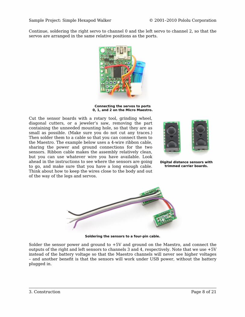
Digital distance sensors withtrimmed carrier boards.
Continue, soldering the right servo to channel 0 and the left servo to channel 2, so that theservos are arranged in the same relative positions as the ports.
Connecting the servos to ports0, 1, and 2 on the Micro Maestro.
Cut the sensor boards with a rotary tool, grinding wheel,diagonal cutters, or a jeweler’s saw, removing the partcontaining the unneeded mounting hole, so that they are assmall as possible. (Make sure you do not cut any traces.)Then solder them to a cable so that you can connect them tothe Maestro. The example below uses a 4-wire ribbon cable,sharing the power and ground connections for the twosensors. Ribbon cable makes the assembly relatively clean,but you can use whatever wire you have available. Lookahead in the instructions to see where the sensors are goingto go, and make sure that you have a long enough cable.Think about how to keep the wires close to the body and outof the way of the legs and servos.
Soldering the sensors to a four-pin cable.
Solder the sensor power and ground to +5V and ground on the Maestro, and connect theoutputs of the right and left sensors to channels 3 and 4, respectively. Note that we use +5Vinstead of the battery voltage so that the Maestro channels will never see higher voltages– and another benefit is that the sensors will work under USB power, without the batteryplugged in.
Sample Project: Simple Hexapod Walker © 2001–2010 Pololu Corporation
3. Construction Page 8 of 21
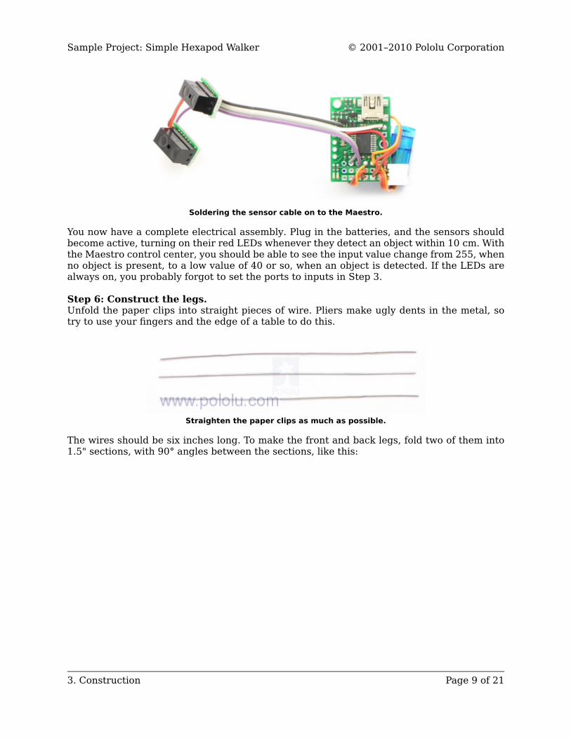
Soldering the sensor cable on to the Maestro.
You now have a complete electrical assembly. Plug in the batteries, and the sensors shouldbecome active, turning on their red LEDs whenever they detect an object within 10 cm. Withthe Maestro control center, you should be able to see the input value change from 255, whenno object is present, to a low value of 40 or so, when an object is detected. If the LEDs arealways on, you probably forgot to set the ports to inputs in Step 3.
Step 6: Construct the legs.Unfold the paper clips into straight pieces of wire. Pliers make ugly dents in the metal, sotry to use your fingers and the edge of a table to do this.
Straighten the paper clips as much as possible.
The wires should be six inches long. To make the front and back legs, fold two of them into1.5" sections, with 90° angles between the sections, like this:
Sample Project: Simple Hexapod Walker © 2001–2010 Pololu Corporation
3. Construction Page 9 of 21
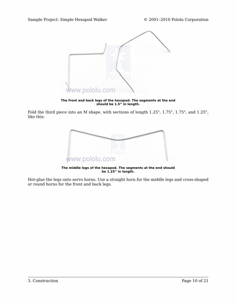
The front and back legs of the hexapod. The segments at the endshould be 1.5” in length.
Fold the third piece into an M shape, with sections of length 1.25", 1.75", 1.75", and 1.25",like this:
The middle legs of the hexapod. The segments at the end shouldbe 1.25” in length.
Hot-glue the legs onto servo horns. Use a straight horn for the middle legs and cross-shapedor round horns for the front and back legs.
Sample Project: Simple Hexapod Walker © 2001–2010 Pololu Corporation
3. Construction Page 10 of 21
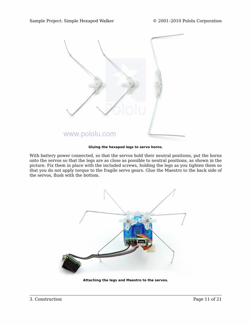
Gluing the hexapod legs to servo horns.
With battery power connected, so that the servos hold their neutral positions, put the hornsonto the servos so that the legs are as close as possible to neutral positions, as shown in thepicture. Fix them in place with the included screws, holding the legs as you tighten them sothat you do not apply torque to the fragile servo gears. Glue the Maestro to the back side ofthe servos, flush with the bottom.
Attaching the legs and Maestro to the servos.
Sample Project: Simple Hexapod Walker © 2001–2010 Pololu Corporation
3. Construction Page 11 of 21
Important: Never apply torque to the legs with your hands, attempt to preventthem from moving, or backdrive them. Servo gears can be easily broken, so theyshould only ever move under their own power. Use the Maestro Control Center toexperiment with different positions, instead of forcing the servos.
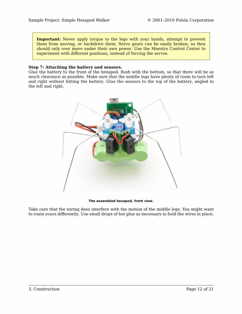
Step 7: Attaching the battery and sensors.Glue the battery to the front of the hexapod, flush with the bottom, so that there will be asmuch clearance as possible. Make sure that the middle legs have plenty of room to turn leftand right without hitting the battery. Glue the sensors to the top of the battery, angled tothe left and right.
The assembled hexapod, front view.
Take care that the wiring does interfere with the motion of the middle legs. You might wantto route yours differently. Use small drops of hot glue as necessary to hold the wires in place.
Sample Project: Simple Hexapod Walker © 2001–2010 Pololu Corporation
3. Construction Page 12 of 21
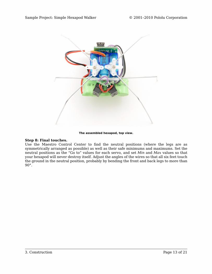
The assembled hexapod, top view.
Step 8: Final touches.Use the Maestro Control Center to find the neutral positions (where the legs are assymmetrically arranged as possible) as well as their safe minimums and maximums. Set theneutral positions as the “Go to” values for each servo, and set Min and Max values so thatyour hexapod will never destroy itself. Adjust the angles of the wires so that all six feet touchthe ground in the neutral position, probably by bending the front and back legs to more than90°.
Sample Project: Simple Hexapod Walker © 2001–2010 Pololu Corporation
3. Construction Page 13 of 21
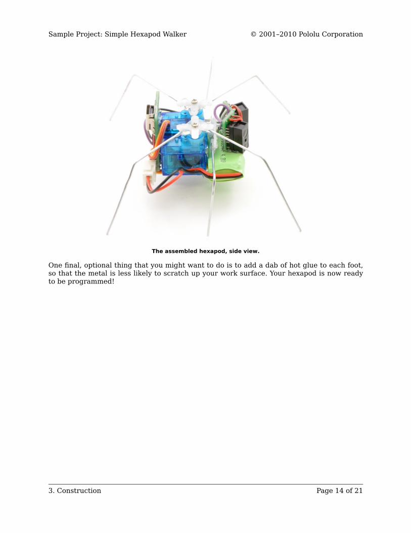
The assembled hexapod, side view.
One final, optional thing that you might want to do is to add a dab of hot glue to each foot,so that the metal is less likely to scratch up your work surface. Your hexapod is now readyto be programmed!
Sample Project: Simple Hexapod Walker © 2001–2010 Pololu Corporation
3. Construction Page 14 of 21
4. Sequencing the Hexapod GaitGaitsNow that you have constructed your hexapod, it is time to make it walk. A method of walkingforward with legs is called a gait, and animals or robots with many degrees of freedom havea variety of gaits available – humans can walk, run, hop, or skip; horses can walk, trot,canter, or gallop, and so on. Your hexapod is so simple that it has just one possible gait forforward motion, called the tripod gait.
In the tripod gait, your hexapod has three feet in contact with the ground at all times: thefront and back legs on one side and the middle leg on the other side. The angle of the middleservo determines which side is up and which side is down. It achieves forward motion bypushing those feet backwards against the ground while the other feet move forward throughthe air. Then the hexapod shifts its weight to the other three feet and moves forward in thesame way. By continuously shifting its weight using the middle legs, then moving the raisedfeet forward, it walks forward.
Walking forward with the Maestro Control CenterYou can easily assemble motion sequences using the Maestro Control Center’s sequencerfeature. For documentation on the sequencer, see Section 4.c of the Micro MaestroUser’s Guide [http://www.pololu.com/docs/0J40].
Use the controls on the Status tab of the Maestro Control center to move your hexapodto each of these four positions, pressing the “Save Frame” button after each, to save asequence.
Sample Project: Simple Hexapod Walker © 2001–2010 Pololu Corporation
4. Sequencing the Hexapod Gait Page 15 of 21
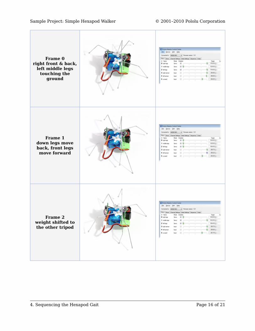
Frame 0right front & back,
left middle legstouching the
ground
Frame 1down legs moveback, front legsmove forward
Frame 2weight shifted tothe other tripod
Sample Project: Simple Hexapod Walker © 2001–2010 Pololu Corporation
4. Sequencing the Hexapod Gait Page 16 of 21
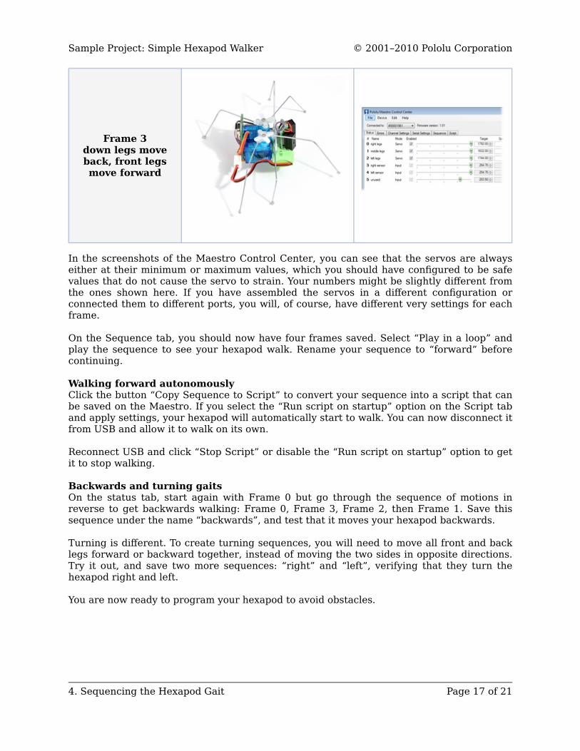
Frame 3down legs moveback, front legsmove forward
In the screenshots of the Maestro Control Center, you can see that the servos are alwayseither at their minimum or maximum values, which you should have configured to be safevalues that do not cause the servo to strain. Your numbers might be slightly different fromthe ones shown here. If you have assembled the servos in a different configuration orconnected them to different ports, you will, of course, have different very settings for eachframe.
On the Sequence tab, you should now have four frames saved. Select “Play in a loop” andplay the sequence to see your hexapod walk. Rename your sequence to “forward” beforecontinuing.
Walking forward autonomouslyClick the button “Copy Sequence to Script” to convert your sequence into a script that canbe saved on the Maestro. If you select the “Run script on startup” option on the Script taband apply settings, your hexapod will automatically start to walk. You can now disconnect itfrom USB and allow it to walk on its own.
Reconnect USB and click “Stop Script” or disable the “Run script on startup” option to getit to stop walking.
Backwards and turning gaitsOn the status tab, start again with Frame 0 but go through the sequence of motions inreverse to get backwards walking: Frame 0, Frame 3, Frame 2, then Frame 1. Save thissequence under the name “backwards”, and test that it moves your hexapod backwards.
Turning is different. To create turning sequences, you will need to move all front and backlegs forward or backward together, instead of moving the two sides in opposite directions.Try it out, and save two more sequences: “right” and “left”, verifying that they turn thehexapod right and left.
You are now ready to program your hexapod to avoid obstacles.
Sample Project: Simple Hexapod Walker © 2001–2010 Pololu Corporation
4. Sequencing the Hexapod Gait Page 17 of 21
5. Using a Script for Obstacle AvoidanceThe Micro Maestro has an internal scripting language that can store sequences, readsensors, and link everything together to form intelligent behaviors, making your hexapodtruly autonomous. For complete documentation on the scripting language, see Section 6 ofthe Micro Maestro User’s Guide [http://www.pololu.com/docs/0J40].
Once you have set up all of your basic gaits, erase your script, then click the “Copy AllSequences to Script” button on the Sequence tab. This button adds a set of subrountinesthat you can use to access the various gaits from within a script.
You can then call these subroutines from your script. For example,
beginforwardleft
repeat
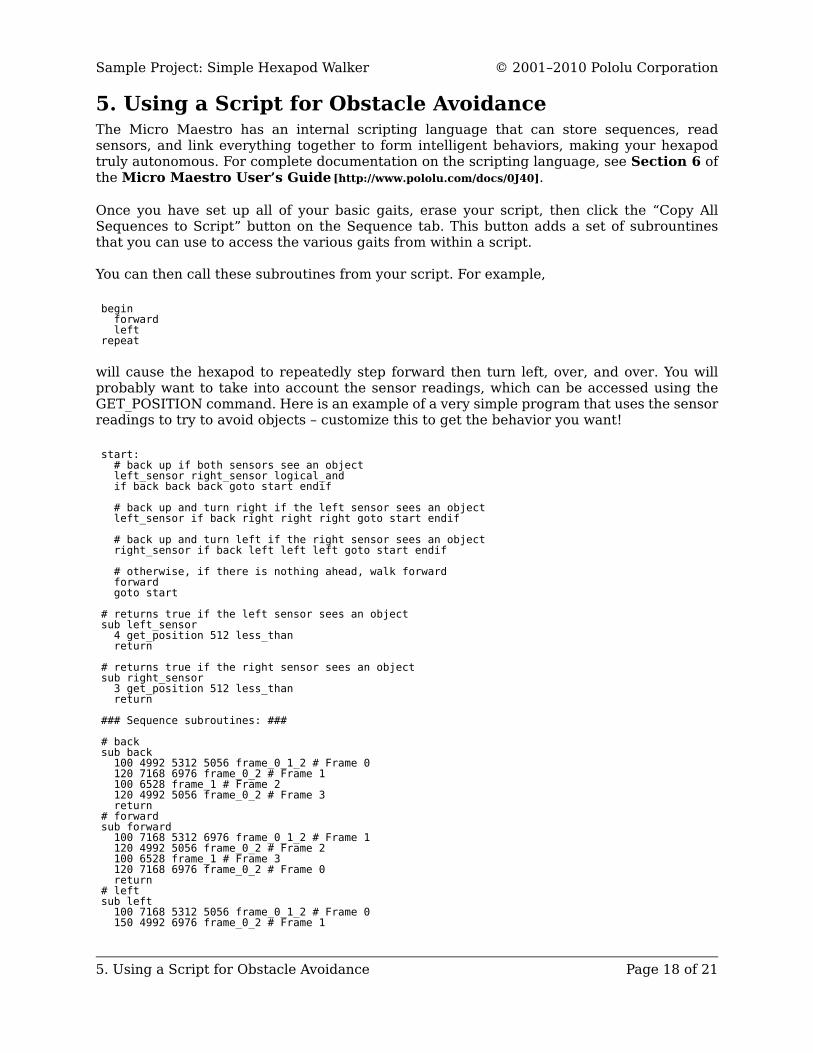
will cause the hexapod to repeatedly step forward then turn left, over, and over. You willprobably want to take into account the sensor readings, which can be accessed using theGET_POSITION command. Here is an example of a very simple program that uses the sensorreadings to try to avoid objects – customize this to get the behavior you want!
start:# back up if both sensors see an objectleft_sensor right_sensor logical_andif back back back goto start endif
# back up and turn right if the left sensor sees an objectleft_sensor if back right right right goto start endif
# back up and turn left if the right sensor sees an objectright_sensor if back left left left goto start endif
# otherwise, if there is nothing ahead, walk forwardforwardgoto start
# returns true if the left sensor sees an objectsub left_sensor
4 get_position 512 less_thanreturn
# returns true if the right sensor sees an objectsub right_sensor
3 get_position 512 less_thanreturn
### Sequence subroutines: ###
# backsub back
100 4992 5312 5056 frame_0_1_2 # Frame 0120 7168 6976 frame_0_2 # Frame 1100 6528 frame_1 # Frame 2120 4992 5056 frame_0_2 # Frame 3return
# forwardsub forward
100 7168 5312 6976 frame_0_1_2 # Frame 1120 4992 5056 frame_0_2 # Frame 2100 6528 frame_1 # Frame 3120 7168 6976 frame_0_2 # Frame 0return
# leftsub left
100 7168 5312 5056 frame_0_1_2 # Frame 0150 4992 6976 frame_0_2 # Frame 1
Sample Project: Simple Hexapod Walker © 2001–2010 Pololu Corporation
5. Using a Script for Obstacle Avoidance Page 18 of 21
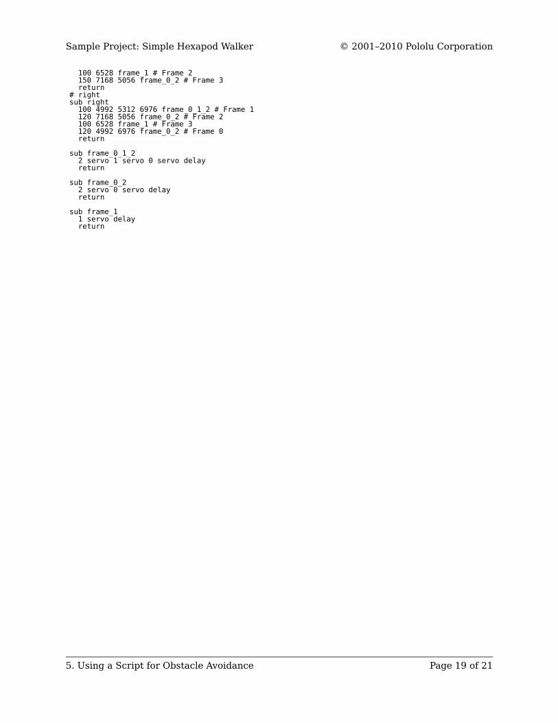
100 6528 frame_1 # Frame 2150 7168 5056 frame_0_2 # Frame 3return
# rightsub right
100 4992 5312 6976 frame_0_1_2 # Frame 1120 7168 5056 frame_0_2 # Frame 2100 6528 frame_1 # Frame 3120 4992 6976 frame_0_2 # Frame 0return
sub frame_0_1_22 servo 1 servo 0 servo delayreturn
sub frame_0_22 servo 0 servo delayreturn
sub frame_11 servo delayreturn
Sample Project: Simple Hexapod Walker © 2001–2010 Pololu Corporation
5. Using a Script for Obstacle Avoidance Page 19 of 21
6. Suggested Modifications and ImprovementsHere are some ideas for improvements or modifications that could be made to the hexapoddesign:
• More complicated scripted behaviors – help your hexapod get out of stuck situationsmore reliably.• More robust sensor readings. The example code only read the sensors once after eachsequence – can you do better than that, and detect obstacles sooner?• Alternative servos – the entire design could be scaled up.• A power switch so that the battery does not have to be unplugged over and over.• Boost regulation [http://www.pololu.com/catalog/product/791] for consistent power froma more compact (lithium?) battery.• QTR sensors [http://www.pololu.com/catalog/product/958] for line following or table-edgedetection.• Light sensors for light-seeking or dark-seeking behaviors.
Sample Project: Simple Hexapod Walker © 2001–2010 Pololu Corporation
6. Suggested Modifications and Improvements Page 20 of 21
7. Conclusion and CommunityThe Micro Maestro can act as the brain for a simple hexapod robot. Three of the Maestro’ssix channels are used for the servos, so there are three channels available for sensors suchas distance sensors, which the hexapod can use to react to its environment. The Maestro’sscripting functionality allows simple behaviors and motion sequences to be programmedonto the device, making the hexapod autonomous.
Did you manage to build the hexapod or something like it? Please join us on our roboticsforum [http://forum.pololu.com/] to ask questions, give feedback, or share your projects. Wewould love to hear about your experiences, and we would be delighted to see anyimprovements or alterations you make!
We will post hexapod projects submitted by others below:
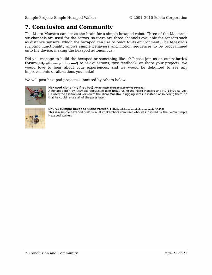
Hexapod clone (my first bot) [http://letsmakerobots.com/node/16683]A hexapod built by letsmakerobots.com user Bruud using the Micro Maestro and HD-1440a servos.He used the assembled version of the Micro Maestro, plugging wires in instead of soldering them, sothat he could re-use all of the parts later.
ShC v1 (Simple hexapod Clone version 1) [http://letsmakerobots.com/node/15458]This is a simple hexapod built by a letsmakerobots.com user who was inspired by the Pololu SimpleHexapod Walker.
Sample Project: Simple Hexapod Walker © 2001–2010 Pololu Corporation
7. Conclusion and Community Page 21 of 21