pollution prevention in machining and metal · pdf filepollution prevention in machining and...
TRANSCRIPT
.........................
Pollution Prevention inMachining and MetalFabrication
A Manual for Technical Assistance ProvidersExcerpts
March 2001 .........................

1Metal fabrication, as it is referred to in this manual, is any process that changes the geometry of a metalworkpiece by deforming it or removing metal from it. Other processes covered in this manual are metal and surfacetreating, such as heat treating and case hardening, as well as metal joining processes, such as welding and soldering. Although the manufacturing of metal parts may involve other processes including plating, coating, and casting, theseprocesses will not be covered in this manual because they were covered in earlier manuals in this series, specificallyPollution Prevention for the Metal Finishing Industry, Pollution Prevention for the Metal Coatings Industry, and,Pollution Prevention for the Primary Metals Industry, available online at http://www.newmoa.org/publications/.
1
CHAPTER 1Overview of Metal Fabrication Industry
BackgroundEverywhere we look, we see fabricated metal products. From paper clips to HVAC housings,
from car bodies to spiral stair cases, countless products start out as metal stock that fabricators bend,punch, drill, grind, thread, and cut to produce various shapes. The metal fabrication process variesgreatly depending on the material being machined, the rate of production, the desired geometry, andother physical requirements of the part or product.
The metal fabrication1 industry also varies greatly in the size, type, and distribution offacilities found in different states throughout the United States. For example, metal fabricationfacilities in the Northeast are usually small-to-medium sized with older equipment, and the keyproducts they manufacture are bearings, fire arms, aerospace, automotive, machine and perishabletools, electrical components, and wire and cable (U.S. EPA 1995). Table 1.1 lists the number offabricated metal product and machinery manufacturers in the U.S.
States with the largest number of metal fabrication plants are New York, Ohio, Pennsylvania,Michigan, Illinois, Texas, and California. Throughout the U.S., fabricators use 175 million gallonsof metalworking fluids, valued at $800 million, and accounting for 15 percent of the overall value ofsales of industrial oils. Worldwide global annual metalworking fluid consumption is more than 600million gallons (Glenn, 1998).
There are a variety of processes involved in the manufacture of complex metal partsincluding: casting, shaping, metal removal, coating, finishing, heat treating, welding, soldering,brazing, and adhesive joining. This Chapter discusses the processes involved in metal shaping andremoval and provides in-depth background on the properties and types of metalworking fluids. ThisChapter also includes an overview of heat treating, brazing and soldering, adhesive joining, welding,tumbling, buffing, polishing, and honing.
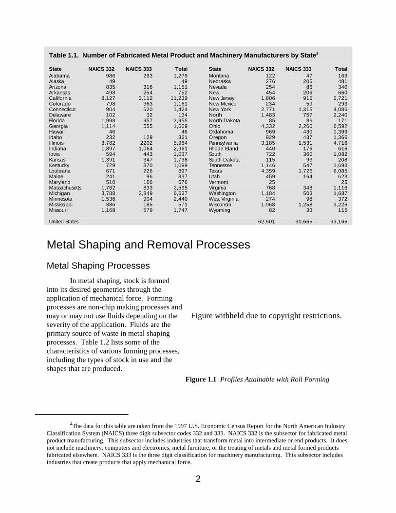
2The data for this table are taken from the 1997 U.S. Economic Census Report for the North American IndustryClassification System (NAICS) three digit subsector codes 332 and 333. NAICS 332 is the subsector for fabricated metalproduct manufacturing. This subsector includes industries that transform metal into intermediate or end products. It doesnot include machinery, computers and electronics, metal furniture, or the treating of metals and metal formed productsfabricated elsewhere. NAICS 333 is the three digit classification for machinery manufacturing. This subsector includesindustries that create products that apply mechanical force.
2
Figure withheld due to copyright restrictions.
Figure 1.1 Profiles Attainable with Roll Forming
Table 1.1. Number of Fabricated Metal Product and Machinery Manufacturers by State2
State NAICS 332 NAICS 333 Total State NAICS 332 NAICS 333 TotalAlabama 986 293 1,279 Montana 122 47 169Alaska 49 49 Nebraska 276 205 481Arizona 835 316 1,151 Nevada 254 86 340Arkansas 498 254 752 New 454 206 660California 8,127 3,112 11,239 New Jersey 1,806 915 2,721Colorado 798 363 1,161 New Mexico 234 59 293Connecticut 904 520 1,424 New York 2,771 1,315 4,086Delaware 102 32 134 North 1,483 757 2,240Florida 1,998 957 2,955 North Dakota 85 86 171Georgia 1,114 555 1,669 Ohio 4,332 2,260 6,592Hawaii 46 46 Oklahoma 969 430 1,399Idaho 232 129 361 Oregon 929 437 1,366Illinois 3,782 2202 5,984 Pennsylvania 3,185 1,531 4,716Indiana 1,897 1,064 2,961 Rhode Island 440 176 616Iowa 594 443 1,037 South 722 360 1,082Kansas 1,391 347 1,738 South Dakota 115 93 208Kentucky 729 370 1,099 Tennessee 1,146 547 1,693Louisiana 671 226 897 Texas 4,359 1,726 6,085Maine 241 96 337 Utah 459 164 623Maryland 510 166 676 Vermont 25 25Massachusetts 1,762 833 2,595 Virginia 768 348 1,116Michigan 3,788 2,849 6,637 Washington 1,184 503 1,687Minnesota 1,536 904 2,440 West Virginia 274 98 372Mississippi 386 185 571 Wisconsin 1,968 1,258 3,226Missouri 1,168 579 1,747 Wyoming 82 33 115
United States 62,501 30,665 93,166
Metal Shaping and Removal Processes
Metal Shaping ProcessesIn metal shaping, stock is formed
into its desired geometries through theapplication of mechanical force. Formingprocesses are non-chip making processes andmay or may not use fluids depending on theseverity of the application. Fluids are theprimary source of waste in metal shapingprocesses. Table 1.2 lists some of thecharacteristics of various forming processes,including the types of stock in use and theshapes that are produced.
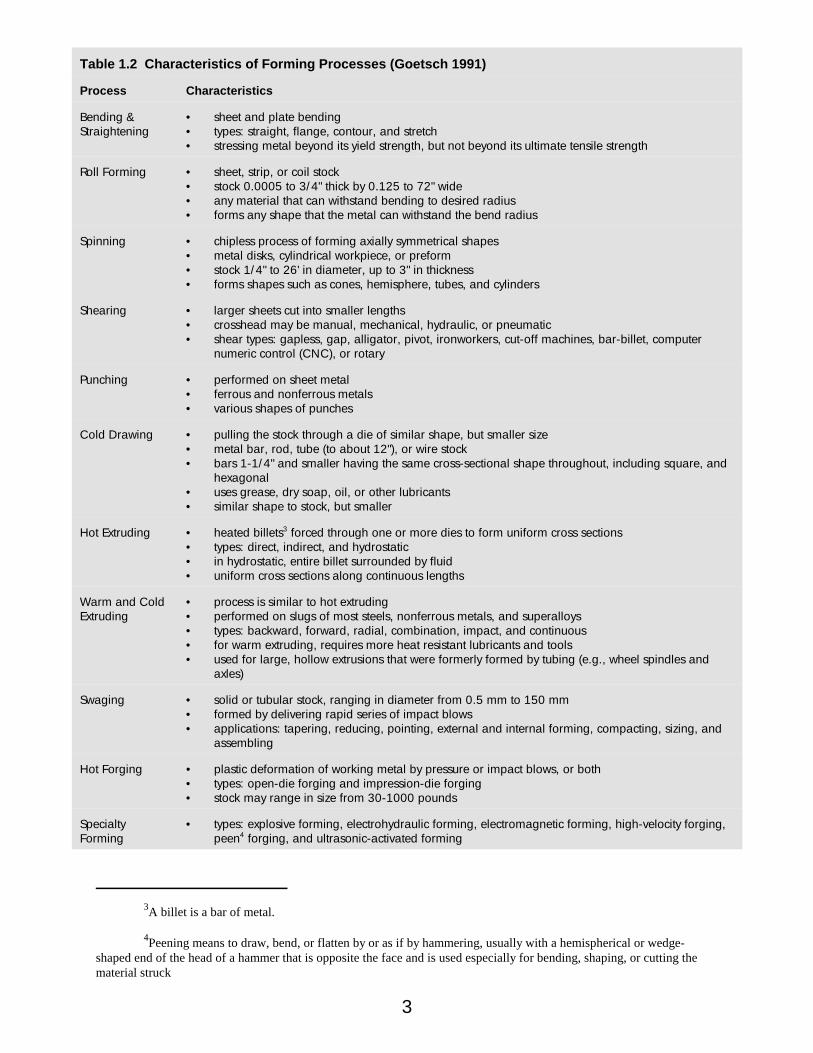
3A billet is a bar of metal.
4Peening means to draw, bend, or flatten by or as if by hammering, usually with a hemispherical or wedge-shaped end of the head of a hammer that is opposite the face and is used especially for bending, shaping, or cutting thematerial struck
3
Table 1.2 Characteristics of Forming Processes (Goetsch 1991)
Process Characteristics
Bending &Straightening
• sheet and plate bending• types: straight, flange, contour, and stretch• stressing metal beyond its yield strength, but not beyond its ultimate tensile strength
Roll Forming • sheet, strip, or coil stock• stock 0.0005 to 3/4" thick by 0.125 to 72" wide• any material that can withstand bending to desired radius• forms any shape that the metal can withstand the bend radius
Spinning • chipless process of forming axially symmetrical shapes• metal disks, cylindrical workpiece, or preform• stock 1/4" to 26' in diameter, up to 3" in thickness• forms shapes such as cones, hemisphere, tubes, and cylinders
Shearing • larger sheets cut into smaller lengths• crosshead may be manual, mechanical, hydraulic, or pneumatic• shear types: gapless, gap, alligator, pivot, ironworkers, cut-off machines, bar-billet, computer
numeric control (CNC), or rotary
Punching • performed on sheet metal• ferrous and nonferrous metals• various shapes of punches
Cold Drawing • pulling the stock through a die of similar shape, but smaller size• metal bar, rod, tube (to about 12"), or wire stock• bars 1-1/4" and smaller having the same cross-sectional shape throughout, including square, and
hexagonal• uses grease, dry soap, oil, or other lubricants• similar shape to stock, but smaller
Hot Extruding • heated billets3 forced through one or more dies to form uniform cross sections• types: direct, indirect, and hydrostatic• in hydrostatic, entire billet surrounded by fluid• uniform cross sections along continuous lengths
Warm and ColdExtruding
• process is similar to hot extruding• performed on slugs of most steels, nonferrous metals, and superalloys• types: backward, forward, radial, combination, impact, and continuous• for warm extruding, requires more heat resistant lubricants and tools• used for large, hollow extrusions that were formerly formed by tubing (e.g., wheel spindles and
axles)
Swaging • solid or tubular stock, ranging in diameter from 0.5 mm to 150 mm• formed by delivering rapid series of impact blows• applications: tapering, reducing, pointing, external and internal forming, compacting, sizing, and
assembling
Hot Forging • plastic deformation of working metal by pressure or impact blows, or both• types: open-die forging and impression-die forging • stock may range in size from 30-1000 pounds
SpecialtyForming
• types: explosive forming, electrohydraulic forming, electromagnetic forming, high-velocity forging,peen4 forging, and ultrasonic-activated forming
5Built-up edge, or BUE, is the condition of chip material adhering or becoming joined to the tool bit.
4
Metal Removal ProcessesIn metal removal processes, stock is given its final geometry through the removal of metal from
stock by a number of processes including: broaching, sawing, turning, boring, drilling, reaming,milling, and grinding. Fluids are used in these processes to provide lubricity, cooling, chip removal,corrosion resistance, and to prevent built-up edge (BUE)5 on the tool bit. The type of fluid used isdependant on a number of factors including substrate compatibility, and the amount of lubricity andcooling required. For more information on fluid characteristics, see the Metal Working FluidOverview later in this chapter. The two typical wastes from metal removal processes are spent metalworking fluids and metal scrap. In the following sections more specific information is presented onthe metal removal processes listed above including tool types, chip characteristics, and fluids used.
Broaching and Sawing
BroachingBroaching is a metal removal process that is performed on flat, round, or contoured substrates.
The multitoothed cutting tools used in broaching have teeth that are generally higher than thepreceding tooth, each removing more material as it passes over the substrate. The tool materialgenerally used is high-speed steel (HSS); however, tungsten carbide tools bits may be used in high-speed broaching applications or broaching of gray cast iron. A variety of metalworking fluids maybe used in broaching, depending on the machining conditions (i.e., speed of cutting, type of materialbeing broached, and design of machine). Broaching may also be performed dry, as fluids are usuallynot required for planing, shaping, and slotting operations because of the intermittent contact of theblade with the workpiece, and the chips formed generally fall away without the use of fluids.
Power HacksawingPower hacksawing is performed using a relatively short, straight blade that is drawn back and
forth over the workpiece. Power hacksaws are used extensively as chop saws and in facilities whereproduction requirements are not high. These saws may be used on all sizes of stock and practicallyall materials.
BandsawingBandsawing uses a continuous band with small teeth that perform one-directional cutting. A
variety of fluids may be used in bandsawing, depending largely on the metal being cut.Metalworking fluids are applied to the cutting area and are carried across the cross section ofmaterial being cut. Fluid may be applied through the blade guides, or through nozzles, spray mists,pressurized mists, and curtain applicators. Bandsawing is more precise than the other methods andcomplex cuts are easily achieved. Compared to other sawing methods, bandsawing is more energy-
6Kerf is a slit or notch made by a saw or cutting torch, or the width of a cut made by a saw or cutting torch.
5
Figure 1.2 Broach Tool
and materials-efficient and creates a smaller kerf.6 The chips that are formed from bandsawing areusually full and uniform.
Circular SawingCircular sawing may be used on billets, forgings, extrusions, bars, tubes, and similar stock,
generally five inches in diameter or less. The use of metalworking fluids is recommended for all metals except brass and cast iron. However, fluids are not generally used when using carbide-tippedblades. Fluids are used in circular sawing more to facilitate flow of the chips than for cooling action,and soluble oils and synthetics are used at a relatively rich mix. Circular sawing creates a wider kerf. Chips generally act as heat sinks allowing workpieces to stay cool, thereby reducing the need forfluid cooling.
Turning and Boring
TurningIn turning operations, a workpiece is rotated about its longitudinal axis on a machine tool called
a lathe. Material is removed by tools mounted on the lathe to create the desired shape. Turning isperformed on surfaces that are concentric with the longitudinal axis of the workpiece. Turning maybe performed with or without the use of fluids; however, dry turning is generally only performed oncast iron or short-run applications. A variety of fluids are used in turning operations, dependinglargely on the material feed rate, tool speed, and workpiece substrate.
6
BoringIn this precision metal removal process, internal cylindrical holes are generated using a single-
point or multiple-edge cutting tool. Boring may be performed by rotating the tool or the workpiece. Boring may produce long, stringy chips depending on the substrate being bored. A variety of fluidsare used in boring operations, depending largely on the material feed rate, tool speed, and workpiecesubstrate.
Drilling and Reaming
Twist DrillsDrilling is the production or enlarging of holes in a workpiece by the relative motion of a cutting
tool. Water-based emulsified oil is the most common metalworking fluid used in these operations. These metalworking fluids minimize friction between the drill and workpiece and reduce frictionbetween the sliding chip and the drill. Because of the limited space involved in drilling, for chips toleave the cutting zone, it is desirable to have small chips form. Coiling of chip material may packdrill flutes, interfering with chip ejection and fluid flow. Hence, more ductile metal may requiremore complex tool designs and geometries.
Counterboring, Spotfacing, and CountersinkingEnlarging a hole for a limited depth is called counterboring. If the cut is shallow so that it
leaves only finished face around the original hole, it is called spotfacing. The cutting of an angularopening into the end of a hole is known as countersinking. A counterbore toolbit usually has straightor helical flutes for the passage of chips or fluids. Speeds and feeds used in counterboring andspotfacing are generally less than those used in drilling. A variety of fluids are used incounterboring, spotfacing, and countersinking operations, depending largely on the material feedrate, tool speed, and workpiece substrate.
ReamingThis process is used for enlarging, smoothing, and/or accurately sizing existing holes by means
of a multi-edge fluted cutting tool. Tools used may be bore, carbide, or coolant-fed reamers. Likecounterboring, spotfacing, and countersinking, there are a variety of fluids that may be used inreaming depending on feeds, speeds, and substrate.
Milling and Grinding
MillingMilling involves the removal of metal in small, individual chips made by each milling cutter. In
face milling, chip thickness varies from a minimum at the entrance and exit, to a maximum along thehorizontal diameter.
GrindingGrinding is performed through basically the same functions as cutting operations. Fluid is
applied to lubricate the chip/grit and grit/workpiece interface, reducing the power required to removea volume of material and thereby reducing the heat generated. In metal cutting, the energy requiredto form a chip is about twice that required to overcome friction between the tool/workpiece andchip/workpiece interface. In grinding, the force necessary to overcome friction is approximately thesame as that required for chip formation, therefore lubrication is critical from a standpoint of power,wheel life, surface finish, heat development, and possible surface damage.
7
Figure 1.3 Schematic of Electrochemical Machining (ECM)
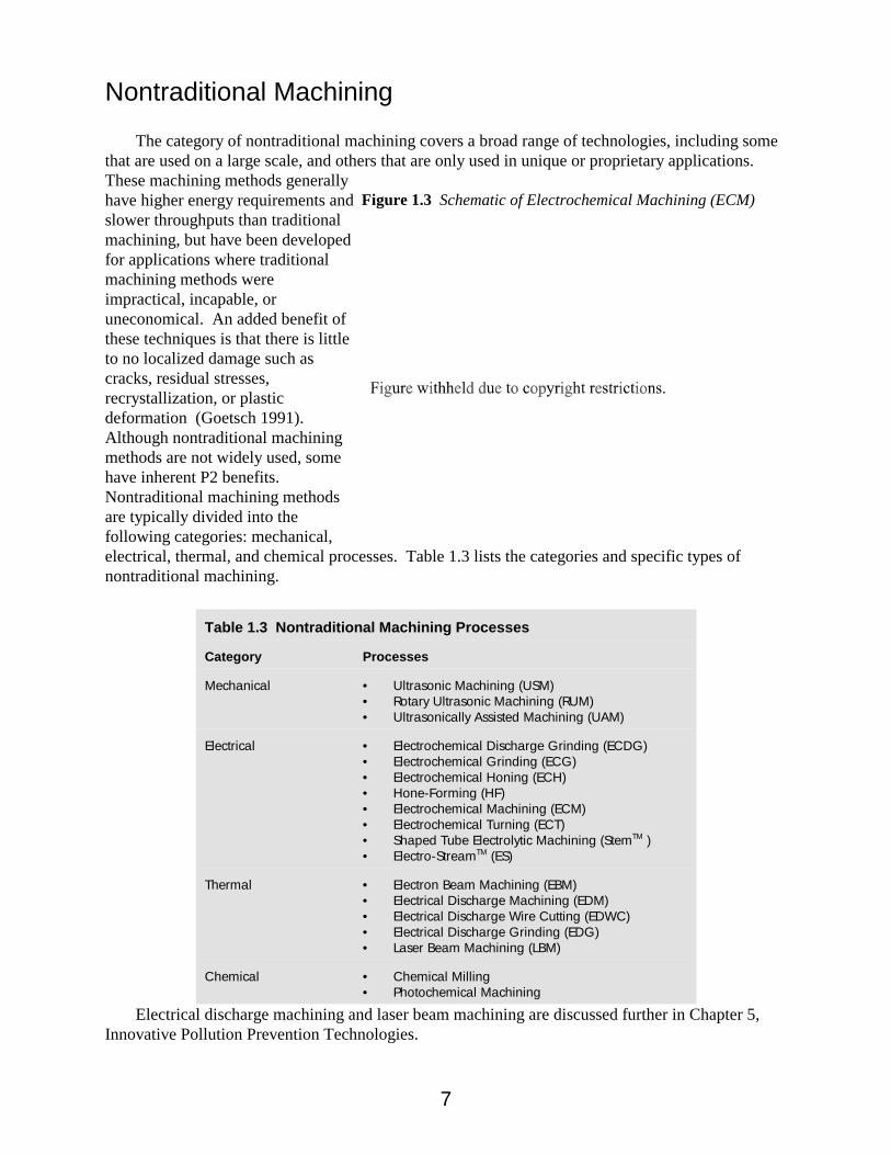
Nontraditional Machining
The category of nontraditional machining covers a broad range of technologies, including somethat are used on a large scale, and others that are only used in unique or proprietary applications. These machining methods generallyhave higher energy requirements andslower throughputs than traditionalmachining, but have been developedfor applications where traditionalmachining methods wereimpractical, incapable, oruneconomical. An added benefit ofthese techniques is that there is littleto no localized damage such ascracks, residual stresses,recrystallization, or plasticdeformation (Goetsch 1991). Although nontraditional machiningmethods are not widely used, somehave inherent P2 benefits. Nontraditional machining methodsare typically divided into thefollowing categories: mechanical,electrical, thermal, and chemical processes. Table 1.3 lists the categories and specific types ofnontraditional machining.
Table 1.3 Nontraditional Machining Processes
Category Processes
Mechanical • Ultrasonic Machining (USM)• Rotary Ultrasonic Machining (RUM)• Ultrasonically Assisted Machining (UAM)
Electrical • Electrochemical Discharge Grinding (ECDG)• Electrochemical Grinding (ECG)• Electrochemical Honing (ECH)• Hone-Forming (HF)• Electrochemical Machining (ECM)• Electrochemical Turning (ECT)• Shaped Tube Electrolytic Machining (StemTM )• Electro-StreamTM (ES)
Thermal • Electron Beam Machining (EBM)• Electrical Discharge Machining (EDM)• Electrical Discharge Wire Cutting (EDWC)• Electrical Discharge Grinding (EDG)• Laser Beam Machining (LBM)
Chemical • Chemical Milling • Photochemical Machining
Electrical discharge machining and laser beam machining are discussed further in Chapter 5,Innovative Pollution Prevention Technologies.
8
Metalworking Fluid Overview
Metalworking fluids perform numerous functions in metal fabrication processes. Fluids can:
• provide cooling for the workpiece and tool• remove chips from the cutting zone• provide lubrication between the tool and the workpiece• prevent corrosion of the workpiece and tool, and• prevent built-up edge (BUE)
This Section will cover tool and workpiece cooling, chip removal, lubrication, the classificationsused for fluids, and the types of fluid components.
Tool and Workpiece CoolingMetalworking fluids provide cooling action to the workpiece and the tool. This prevents
thermal damage to the workpiece, minimizes thermal stressing and brittle hardening of the tool bit,and prevents BUE. Fluids help to reduce these problems by absorbing heat through convection andby reducing the frictional forces, thereby reducing the force and energy requirements and heatgeneration (Kalpakjian 1992). In place of fluids for cooling, some operations may use pressurizedair, a combination of pressurized air and fluid, or other means. For more information on machiningwithout using fluids, see Chapter 5, Dry Machining.
Chip RemovalChips that are formed during chip-making processes can have a tendency to build up in the
cutting area and cause undue stress on the machine tool. Fluids are used to flush chips out of thework zone. The amount of fluid necessary to perform this function is dependant on the chipformation characteristics of the given application. Some processes may be modified to usealternative means of chip removal, such as compressed air or compressed air combined with fluidmist application, which are equally successful at removing chips from the work zone without the useof excessive amounts of fluids and the subsequent waste generation. In other cases, retooling may beperformed to modify chip formation and ejection to prevent chips from building up on the tool or inthe work zone. Additionally, some substrates may be surface treated to modify the chip makingcharacteristics, allowing the chips to break away and exit the cutting area. For more information onalternatives to fluid for chip removal, see Chapter 5, Dry Machining.
LubricationThe amount of lubrication provided by the fluid largely depends on the type of fluid and fluid
additives used. Straight oils provide fair lubricity, but when compounded with active chemical agentssuch as chlorine, sulphur, or phosphate, they provide a great deal more lubrication. The additivesreact with the surface of the workpiece, causing the bonds between metallic fibers to weaken,making it easier for the chip to be formed and removed (Peterson 1995).
9
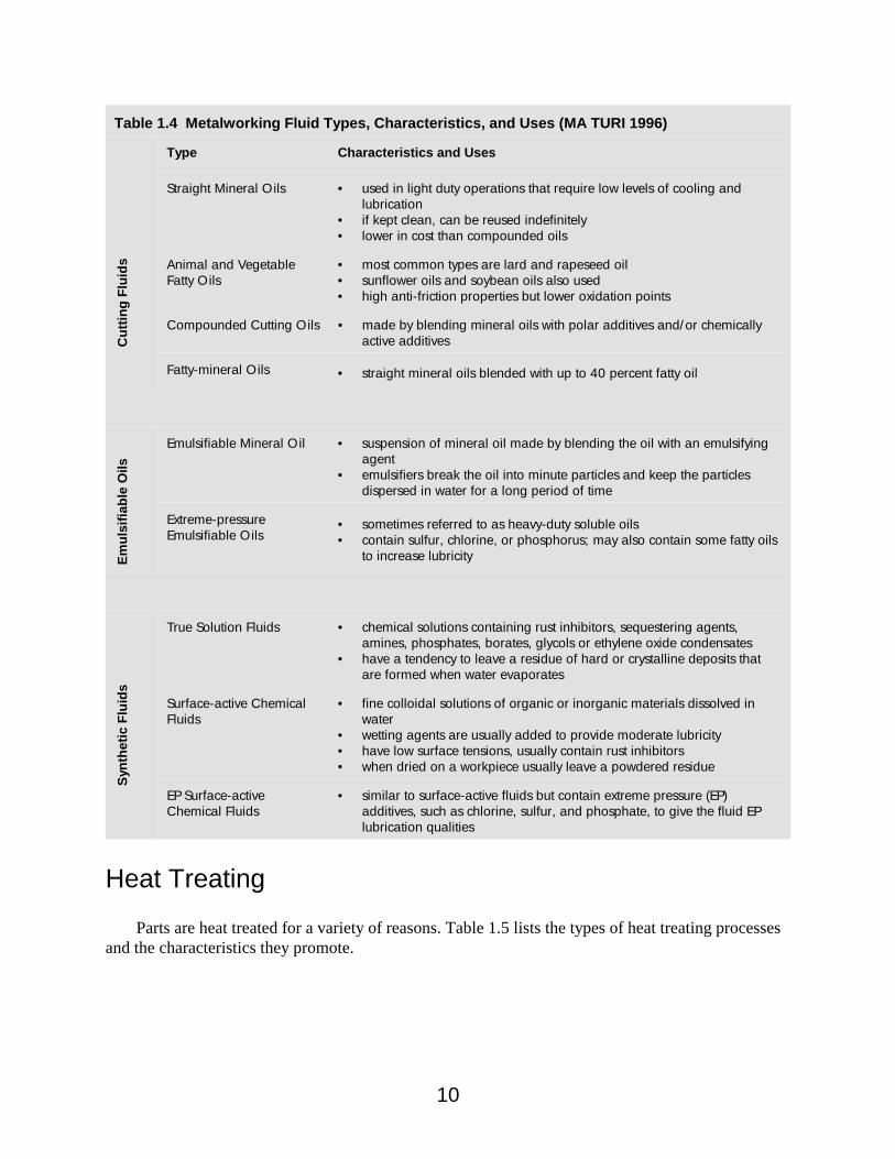
Fluid ClassificationMetalworking fluids have been characterized and classified into many different groups, and the
classifications vary depending on the source of information. In Table 1.4 fluids are characterized bybase fluid type and additives.
A class of lubricants not covered in the table is paste and solid lubricants. They are sometimesused on grinding wheels, sanding disks or belts, and band or circular saws. Types of solid and pastelubricants are: sulphur, solid waxes, grease sticks, molybdenum disulfide, tripoli, graphite, mica,talc, glass, pastes, and soaps (MA TURI 1996).
Fluid Components Metalworking fluids have evolved from straight mineral oils, which were widely used at the turn
of the century, to extremely complex chemistries today. In addition to base oils, fluids may containadditives, such as emulsifiers, corrosion inhibitors, emulsion stabilizers, anitfoaming agents, buffers,extreme pressure additives, biocides, and antimisting agents. The amount of information availablefrom the formulators varies, but often is no more than the formulator is required to list on theMaterial Safety Data Sheet (MSDS), plus the fluid’s compatibility with various substrates, andexamples of processes for which it is well suited.
Metalworking fluids may contain inactive or active chemical additives that provide increasedlubricity. Inactive extreme-pressure (EP) additives, such as chlorine, sulfur or phosphorus, are addedto mineral or compounded oils for machining applications where forces are high. These samechemicals may also be added in concentrations high enough that they become active, and chemicallyinteract with the substrate material to further decrease the mechanical energy needs and frictionalforces between the tool and the workpiece.
Biocides are used in water-based metalworking fluids to control the growth of bacteria, algae,and fungi. Classes of compounds used are phenolics and nonphenolics, formaldehyde release agents,aliphatic derivatives, organosulphur-nitrogen compounds, and some mixtures of these(Shennan 1983).
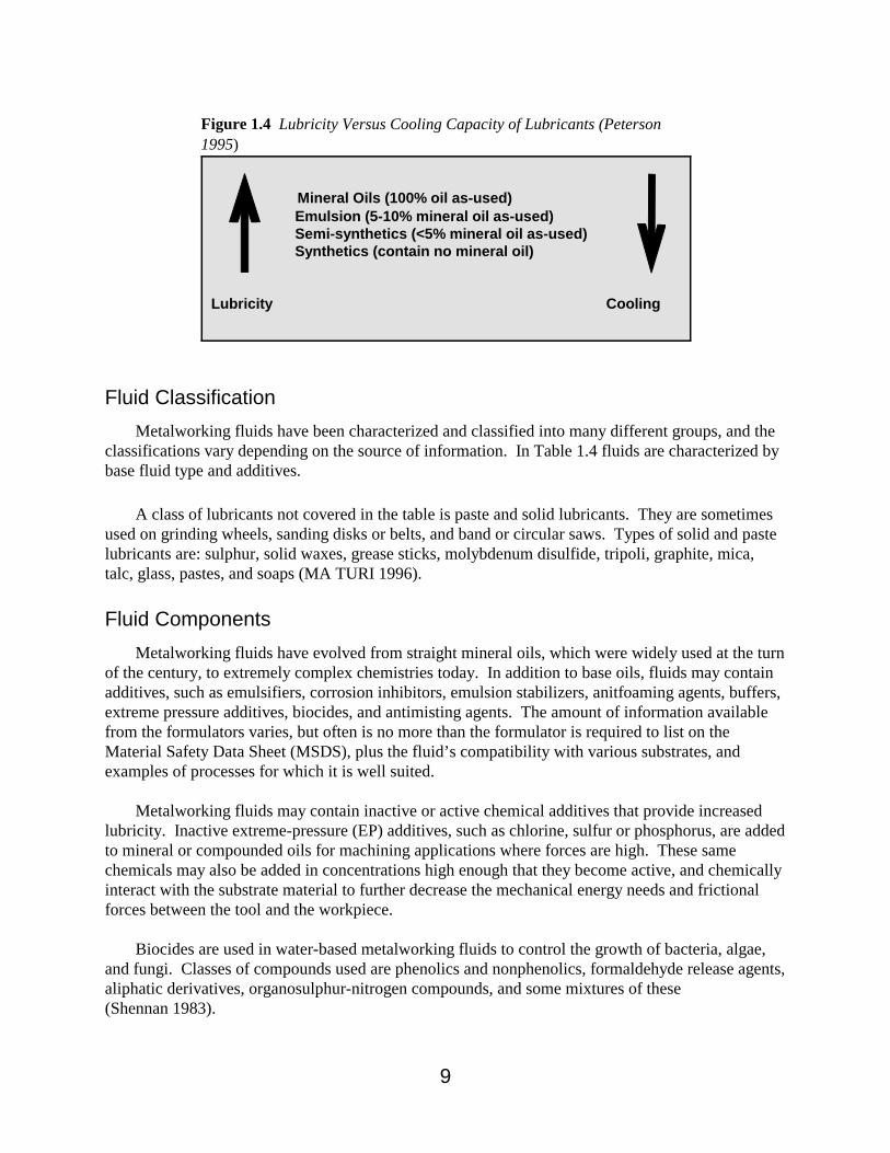
Mineral Oils (100% oil as-used) Emulsion (5-10% mineral oil as-used) Semi-synthetics (<5% mineral oil as-used) Synthetics (contain no mineral oil)
Lubricity Cooling
Figure 1.4 Lubricity Versus Cooling Capacity of Lubricants (Peterson1995)
10
Table 1.4 Metalworking Fluid Types, Characteristics, and Uses (MA TURI 1996)C
uttin
g Fl
uids
Type Characteristics and Uses
Straight Mineral Oils • used in light duty operations that require low levels of cooling andlubrication
• if kept clean, can be reused indefinitely• lower in cost than compounded oils
Animal and VegetableFatty Oils
• most common types are lard and rapeseed oil• sunflower oils and soybean oils also used• high anti-friction properties but lower oxidation points
Compounded Cutting Oils • made by blending mineral oils with polar additives and/or chemicallyactive additives
Fatty-mineral Oils • straight mineral oils blended with up to 40 percent fatty oil
Emul
sifia
ble
Oils
Emulsifiable Mineral Oil • suspension of mineral oil made by blending the oil with an emulsifyingagent
• emulsifiers break the oil into minute particles and keep the particlesdispersed in water for a long period of time
Extreme-pressureEmulsifiable Oils
• sometimes referred to as heavy-duty soluble oils• contain sulfur, chlorine, or phosphorus; may also contain some fatty oils
to increase lubricity
Synt
hetic
Flu
ids
True Solution Fluids • chemical solutions containing rust inhibitors, sequestering agents,amines, phosphates, borates, glycols or ethylene oxide condensates
• have a tendency to leave a residue of hard or crystalline deposits thatare formed when water evaporates
Surface-active ChemicalFluids
• fine colloidal solutions of organic or inorganic materials dissolved inwater
• wetting agents are usually added to provide moderate lubricity• have low surface tensions, usually contain rust inhibitors• when dried on a workpiece usually leave a powdered residue
EP Surface-activeChemical Fluids
• similar to surface-active fluids but contain extreme pressure (EP)additives, such as chlorine, sulfur, and phosphate, to give the fluid EPlubrication qualities
Heat Treating
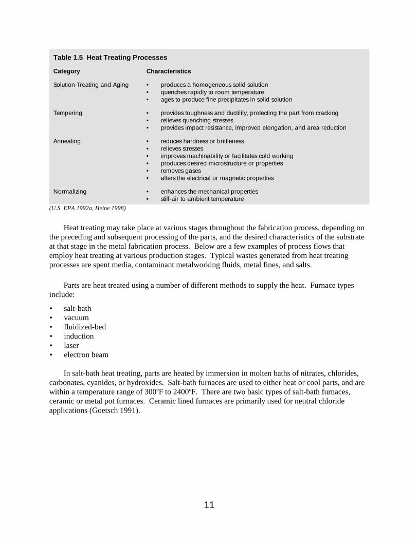
Parts are heat treated for a variety of reasons. Table 1.5 lists the types of heat treating processesand the characteristics they promote.
11
Table 1.5 Heat Treating Processes
Category Characteristics
Solution Treating and Aging • produces a homogeneous solid solution • quenches rapidly to room temperature• ages to produce fine precipitates in solid solution
Tempering • provides toughness and ductility, protecting the part from cracking• relieves quenching stresses• provides impact resistance, improved elongation, and area reduction
Annealing • reduces hardness or brittleness• relieves stresses• improves machinability or facilitates cold working• produces desired microstructure or properties• removes gases• alters the electrical or magnetic properties
Normalizing • enhances the mechanical properties• still-air to ambient temperature
(U.S. EPA 1992a, Heine 1998)
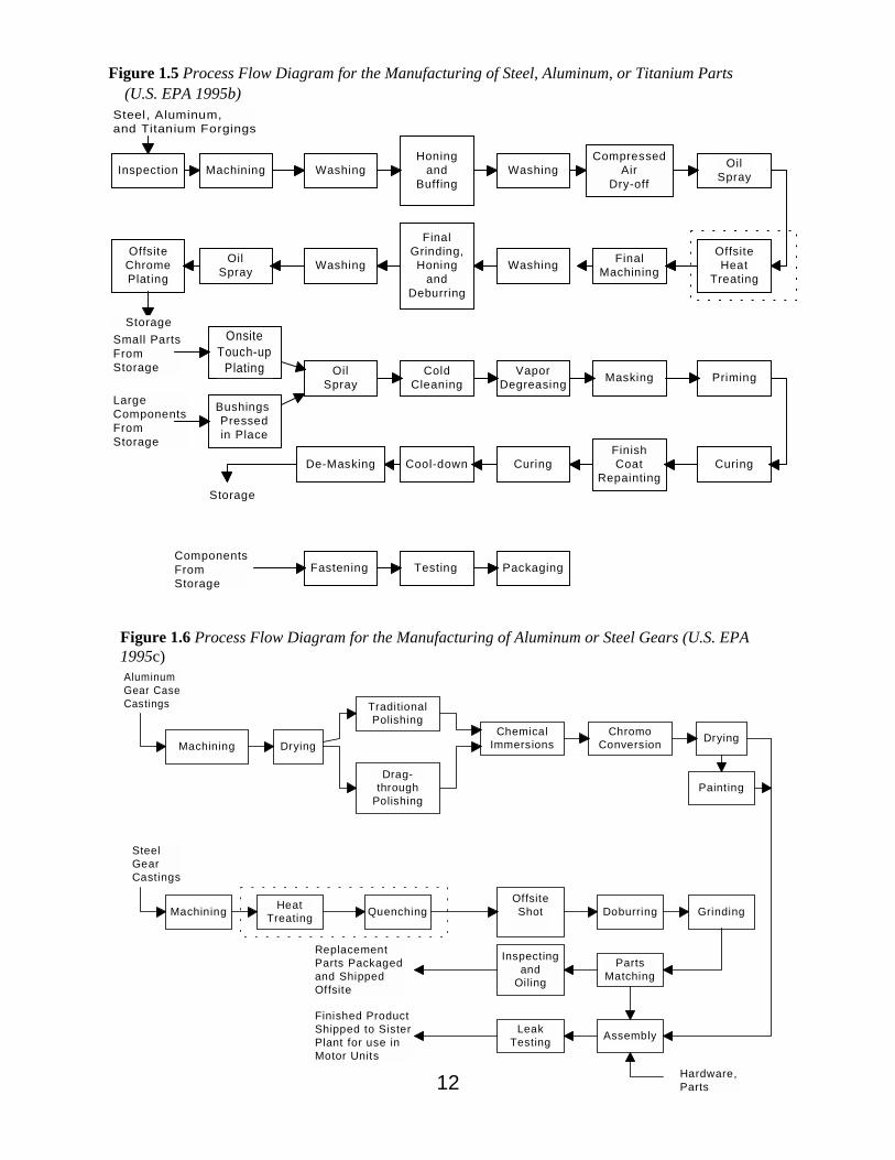
Heat treating may take place at various stages throughout the fabrication process, depending onthe preceding and subsequent processing of the parts, and the desired characteristics of the substrateat that stage in the metal fabrication process. Below are a few examples of process flows thatemploy heat treating at various production stages. Typical wastes generated from heat treatingprocesses are spent media, contaminant metalworking fluids, metal fines, and salts.
Parts are heat treated using a number of different methods to supply the heat. Furnace typesinclude:
• salt-bath• vacuum• fluidized-bed• induction• laser• electron beam
In salt-bath heat treating, parts are heated by immersion in molten baths of nitrates, chlorides,carbonates, cyanides, or hydroxides. Salt-bath furnaces are used to either heat or cool parts, and arewithin a temperature range of 300oF to 2400oF. There are two basic types of salt-bath furnaces,ceramic or metal pot furnaces. Ceramic lined furnaces are primarily used for neutral chlorideapplications (Goetsch 1991).
12
Machining Drying
TraditionalPolishing
Drag-through
Polishing
ChromoConversion Drying
AluminumGear CaseCastings
ChemicalImmersions
Painting
GrindingDoburring
PartsMatching
Assembly
OffsiteShot
LeakTesting
QuenchingHeatTreatingMachining
Inspectingand
Oiling
SteelGearCastings
Hardware,Parts
ReplacementParts Packagedand ShippedOffsite
Finished ProductShipped to SisterPlant for use inMotor Units
Figure 1.6 Process Flow Diagram for the Manufacturing of Aluminum or Steel Gears (U.S. EPA1995c)
Steel, Aluminum,and Titanium Forgings
Inspection Machining WashingHoning
andBuffing
WashingCompressed
AirDry-off
OilSpray
OffsiteHeat
Treating
FinalMachiningWashing
FinalGrinding,Honing
andDeburring
WashingOilSpray
OffsiteChromePlating
OnsiteTouch-up
Plating
Bushings Pressedin Place
OilSpray
ColdCleaning
VaporDegreasing Masking Priming
CuringFinishCoat
RepaintingCuringCool-downDe-Masking
PackagingTestingFastening
Small PartsFrom Storage
LargeComponentsFromStorage
Storage
ComponentsFromStorage
Storage
Figure 1.5 Process Flow Diagram for the Manufacturing of Steel, Aluminum, or Titanium Parts (U.S. EPA 1995b)
7Involving, held by, or resulting from surface tension.
13
In fluidized-bed furnaces, the parts are placed in a furnace filled with media and flowinggaseous media that gives the furnace its fluidized properties. The temperature that the parts areheated to depends on the substrate and the desired characteristics. Parts are then cooled byquenching (see below) or by allowing them to return to ambient air temperature. There are a varietyof media available for use in fluidized-bed furnaces, such as aluminum oxide, silicon carbide, orzirconia sand.
A vacuum furnace is a container that is evacuated and heated by electric radiant heat. Becauseof advances in design and control, vacuum furnaces are being used as an alternative to salt-bath andatmosphere-controlled furnaces. Vacuum, induction, laser, and electron beam heat treating arecovered in more depth in Chapter 6 because they are relatively low polluting methods of heattreating.
Surface (Case) HardeningSimilar in nature to heat treating, surface or case hardening involves heating parts to impart
certain surface characteristics. Surface hardening is a thermochemical treatment in which thechemical composition of the steel surface is altered. The types of surface hardening are carbonizing,nitriding, carbonitriding, chromizing, and boronizing. Each type involves heating the substrate in acontrolled environment with the presence of a source of the desired case material. Another type ofhardening is selective surface hardening, which does not alter the chemical composition of the metalsurface but alters the physical properties of the metal surface. The different types of selectivesurface hardening are: induction hardening, high-frequency resistance hardening, flame hardening,electron-beam hardening, and laser hardening (Goetsch 1991).
QuenchingMetals are cooled after heat treating at varying rates and to varying degrees depending on the
type of metal and the desired characteristics. Cooling media may be air, oil, polymer, water, ormolten salts, and may be applied in streaming gaseous form, liquid baths, fog, or mist. Thequenchant media and application method used depends on the rate of cooling desired, which is againdictated by the phase characteristics of the substrate and the desired characteristics. Typical wastesfrom quenching operations are spent quenchant and contaminant metalworking fluid.
Quenching is an integral part of liquid carburizing, liquid cyaniding, and liquid nitriding. Whenthe part absorbs sufficient quantities of carbon, cyanide, or nitrogen from a liquid salt bath, it is oftenquenched in mineral oil, paraffin-based oil, water, or brine to develop a hard surface layer (excepttool steels which are liquid nitride cooled) (Goetsch 1991).
Brazing and Soldering
Brazing and soldering use heat and filler metals to produce metallurgical bonds between metalsurfaces without melting the base metals. In brazing, the filler metals have liquate temperaturesabove 840oF, but below those of the metals being joined. The filler metals are distributed betweenthe surfaces to be joined by capillary7 action. In soldering, the filler metals have liquate
8Borax is a white crystalline compound that consists of a hydrated sodium borate that occurs as a mineral or isprepared from other minerals.
9Intermetallic-type bonds, by definition, are composed of two or more metals or a metal and a nonmetal.
10Rosin is a translucent amber-colored to almost black brittle friable resin that is obtained by chemical meansfrom the oleoresin or deadwood of pine trees or from tall oil.
14
temperatures below 840oF and the filler metals are distributed by both capillary action and wettingbetween the surfaces of the components being soldered (Goetsch 1991). Typical wastes andemissions from brazing and soldering processes are used or vaporized fluxes, spent dip baths, fillermetal splatter or scrap, and spent rinse baths.
BrazingBrazing is used in a broad range of applications, from jewelry to aerospace. The use of brazing
over welding, adhesive joining, or other methods of joining metals depends on the complexity of thegeometries to be joined, the size of the components to be joined, the number of joints to be made, thethickness of the sections, and the service requirements. Heat is applied to the joint to be brazed byone of the following means: torch, induction, dip, infrared, furnace, resistance, laser, electron beam,and exothermic. The method of applying filler metal to the joint is application specific and some ofthe filler metals may only be brazed by one of the heating methods. Filler metals may be in the formof rings, shims, paste alloys, molten baths, or bars.
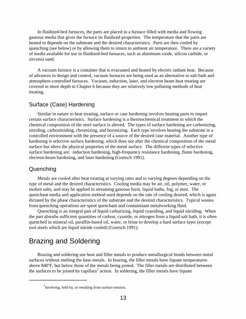
Fluxes are used in brazing to facilitate the flow of molten metal into the joint and eliminateoxides that could have a harmful effect on the integrity of the joint. Fluxes are available in bothpowder and paste form and the type used depends on the application. One of the most commonlyused flux materials is borax,8 although there are a variety of other fluxes available. Brazing ofaluminum requires special flux that contain metallic halide salts, sodium chlorides, and potassiumchlorides. Like the use of a specific filler metal, the method for applying filler metals depends on thetype of brazing employed. After brazing, residual flux is usually removed by immersing in a hotwater bath. This is necessary due to the corrosive nature of many of the fluxes used in brazing. Table 1.6 lists some of the advantages and disadvantages of brazing compared to other joiningmethods.
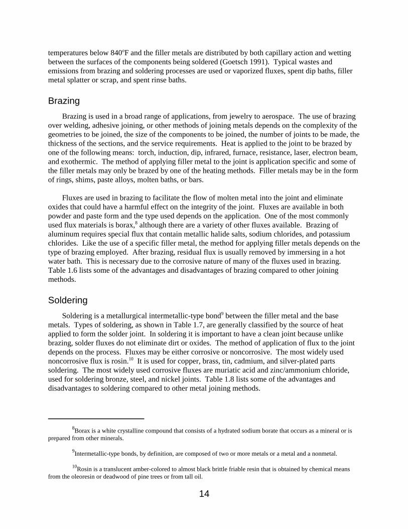
SolderingSoldering is a metallurgical intermetallic-type bond9 between the filler metal and the base
metals. Types of soldering, as shown in Table 1.7, are generally classified by the source of heatapplied to form the solder joint. In soldering it is important to have a clean joint because unlikebrazing, solder fluxes do not eliminate dirt or oxides. The method of application of flux to the jointdepends on the process. Fluxes may be either corrosive or noncorrosive. The most widely usednoncorrosive flux is rosin.10 It is used for copper, brass, tin, cadmium, and silver-plated parts soldering. The most widely used corrosive fluxes are muriatic acid and zinc/ammonium chloride,used for soldering bronze, steel, and nickel joints. Table 1.8 lists some of the advantages anddisadvantages to soldering compared to other metal joining methods.
15
Table 1.6 Advantages and Limitations of Brazing Compared to Other Joining Methods
Advantages Limitations
• effective on joints inaccessible to welding• thin-walled tubes and light-gage sheet metal can be
brazed• can join dissimilar materials• creates leaktight joints• joining of materials at temperatures below 1300oF• multiple joints can be made at one time• less skilled operators required for high speed
applications• brazed joints are ductile• brazing is readily automated
• requires close mating of parts• large assemblies, although brazable, may be more
economically made by welding
(Goetsch 1991)
Table 1.7 Types of Soldering and Their Characteristics
Heating Method Heat Source Characteristics
Conduction Heating Irons and Guns • generally used when the number of joints is few
Hot Plates • suitable for automation• longer cooling time required
Dip • high production volumes• minimal equipment costs• dross formation is an issue• bath requires skimming
Wave • for printed wire board (PWB) manufacturing
Jet • jet nozzles of various configuration allow more preciseapplication of solder
• may be used with oil for better wetting• requires post cleaning for oil removal
Convection Heating Torches • used for soldering preforms and paste alloys• also used for line-soldering enclosures for hermetic sealing
Ovens orFurnaces
• controlled atmospheres used to eliminate oxidation and theneed for corrosive fluxes
Vapor-phaseSoldering
• boiling fluorinated hydrocarbon used as heat-transfer medium• used for joining small parts with unusual configurations
Hot GasBlankets
• used for joining small assemblies
Resistance Soldering NA • used for electronics
Radiation Heating Unfocused • uses ordinary lamps (light waves) as heat source
16
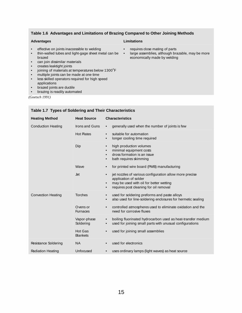
Table 1.7 Types of Soldering and Their Characteristics (continued)
Radiation Heating(continued)
Focused • laser is one source of heat used• often used on miniature soldering
Induction Soldering NA • electromagnetic induction • part to be soldered is the heating element• flux and solder may be applied prior to joining
Ultrasonics Soldering NA • cavitation removes oxides from surfaces• does not require flux in many applications• no wetting provided• may need to pretin or use preformed or solid wire solder on the
joint
Other: NA • spray gun• screen• abrasion• sweat
(Goetsch 1991)
Table 1.8 Advantages and Disadvantages of Solder JoiningCompared to Other Joining Methods
Advantages Limitations
• versatility• reliability• precise control• fast production• low cost
• poor mechanical properties
Adhesive Joining
Adhesive joints are prepared by applying adhesives and then curing or setting the adhesive. Curing is the change in physical properties of the adhesive by chemical reaction, which may becondensation, polymerization, or vulcanization, often accomplished by heat and/or catalyst, and withor without pressure. Setting is the conversion of an adhesive into a fixed or hardened state bychemical or physical reaction (Goetsch 1991). Typical waste streams and emissions from adhesivejoining processes are excess adhesives and volatile organic compound (VOC) and hazardous airpollutant (HAP) emissions from carrier solvents and primers. Adhesive joining operations aredefined by the type of adhesive, the method of curing, and the method of adhesive application. Table1.9 lists the most commonly used types of adhesives.
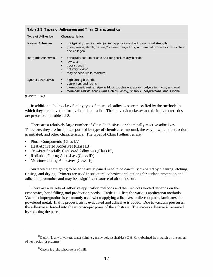
11Dextrin is any of various water-soluble gummy polysaccharides (C6H10O5)n obtained from starch by the actionof heat, acids, or enzymes.
12Casein is a phosphoprotein of milk.
17
Table 1.9 Types of Adhesives and Their Characteristics
Type of Adhesive Characteristics
Natural Adhesives • not typically used in metal joining applications due to poor bond strength• gums, resins, starch, dextrin,11 casein,12 soya flour, and animal products such as blood
and collagen
Inorganic Adhesives • principally sodium silicate and magnesium oxychloride• low cost• poor strength• not very flexible• may be sensitive to moisture
Synthetic Adhesives • high-strength bonds• elastomers and resins• thermoplastic resins: styrene block copolymers, acrylic, polyolefin, nylon, and vinyl• thermoset resins: acrylic (anaerobics), epoxy, phenolic, polyurethane, and silicone
(Goetsch 1991)
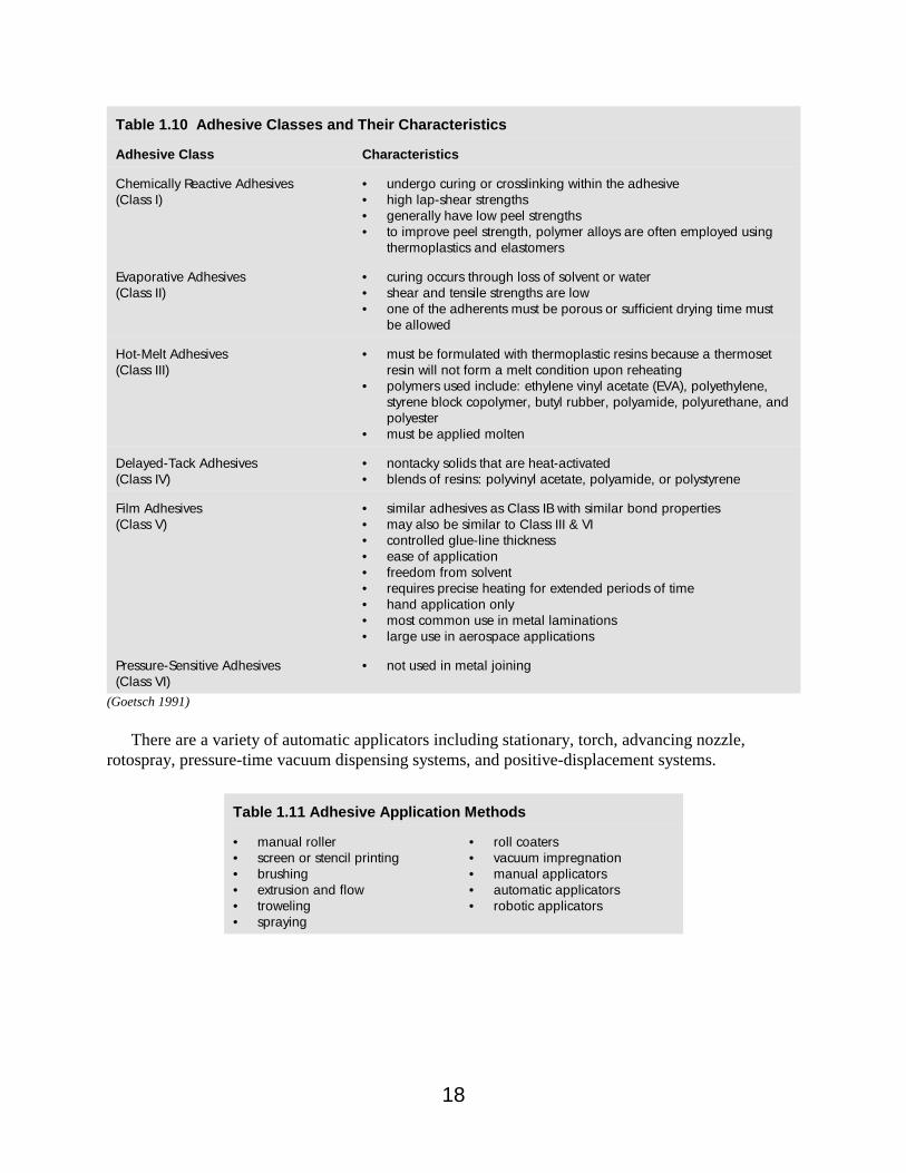
In addition to being classified by type of chemical, adhesives are classified by the methods inwhich they are converted from a liquid to a solid. The conversion classes and their characteristicsare presented in Table 1.10.
There are a relatively large number of Class I adhesives, or chemically reactive adhesives.Therefore, they are further categorized by type of chemical compound, the way in which the reactionis initiated, and other characteristics. The types of Class I adhesives are:
• Plural Components (Class IA)• Heat-Activated Adhesives (Class IB)• One-Part Specially Catalyzed Adhesives (Class IC)• Radiation-Curing Adhesives (Class ID)• Moisture-Curing Adhesives (Class IE)
Surfaces that are going to be adhesively joined need to be carefully prepared by cleaning, etching,rinsing, and drying. Primers are used in structural adhesive applications for surface protection andadhesion promotion and may be a significant source of air emissions.
There are a variety of adhesive application methods and the method selected depends on theeconomics, bond filling, and production needs. Table 1.11 lists the various application methods.Vacuum impregnation is commonly used when applying adhesives to die-cast parts, laminates, andpowdered metal. In this process, air is evacuated and adhesive is added. Due to vacuum pressures,the adhesive is forced into the microscopic pores of the substrate. The excess adhesive is removedby spinning the parts.
18
Table 1.10 Adhesive Classes and Their Characteristics
Adhesive Class Characteristics
Chemically Reactive Adhesives(Class I)
• undergo curing or crosslinking within the adhesive• high lap-shear strengths• generally have low peel strengths• to improve peel strength, polymer alloys are often employed using
thermoplastics and elastomers
Evaporative Adhesives(Class II)
• curing occurs through loss of solvent or water• shear and tensile strengths are low• one of the adherents must be porous or sufficient drying time must
be allowed
Hot-Melt Adhesives(Class III)
• must be formulated with thermoplastic resins because a thermosetresin will not form a melt condition upon reheating
• polymers used include: ethylene vinyl acetate (EVA), polyethylene,styrene block copolymer, butyl rubber, polyamide, polyurethane, andpolyester
• must be applied molten
Delayed-Tack Adhesives(Class IV)
• nontacky solids that are heat-activated• blends of resins: polyvinyl acetate, polyamide, or polystyrene
Film Adhesives(Class V)
• similar adhesives as Class IB with similar bond properties• may also be similar to Class III & VI• controlled glue-line thickness• ease of application• freedom from solvent• requires precise heating for extended periods of time• hand application only• most common use in metal laminations• large use in aerospace applications
Pressure-Sensitive Adhesives(Class VI)
• not used in metal joining
(Goetsch 1991)
There are a variety of automatic applicators including stationary, torch, advancing nozzle,rotospray, pressure-time vacuum dispensing systems, and positive-displacement systems.
Table 1.11 Adhesive Application Methods
• manual roller• screen or stencil printing• brushing• extrusion and flow• troweling• spraying
• roll coaters• vacuum impregnation• manual applicators• automatic applicators• robotic applicators
13Muslin is a plain-woven sheer to coarse cotton fabric.
14Sisal is a strong durable white fiber used especially for hard fiber cordage and twine.
19
Welding and Weld Cutting
Nearly all metal fabrication processes employ some form of welding. Welding processes vary byheat source, pressure, and filler metals. The various welding processes are:
• oxyfuel gas welding and cutting• arc welding and cutting• laser beam welding and cutting• Thermit welding• diffusion welding• friction welding• ultrasonic welding• explosive welding and cladding• other solid-state welding
Typical wastes from welding and weld cutting processes are dross, slag, spent electrodes, andscrap metal.
Buffing and Polishing
Buffing and polishing are performed to smooth and shine the surface of parts to give the productits finished look. A variety of buffing and polishing machines are used, including polishing andbuffing lathes, high-speed polishing machines, or off-hand buffing and polishing pads. Wheels, orbuffs, are typically made of muslin cloth,13 mill-treated cloth, sisal,14 denim, and flannel. The wheelsare treated with buffing or polishing compounds that are selected based on the substrate and the levelof polishing required for the specific application. Buffing and polishing compounds come in variousforms including spray, paste, stick, and powder. Typical wastes from buffing and polishingoperations include excess polishing or buffing compounds and spent wheels or pads.
Tumbling and Vibratory Finishing
Tumbling and vibratory finishing are performed for cleaning, oxide removal/descaling, polishing,brightening, and edge-breaking/burr removal. There are wet and dry tumbling and vibratoryprocesses that use a variety of media including ceramics, stone, glass beads, metal shot, nut shells,corn husks, hardwoods, and plastic/resin beads. For wet processes, these media are used incombination with chemistries, such as cleaners and detergents, chelated burnishing compounds,acids, or water. Machines for wet and dry processes may be vibratory bowls, tumblers, centrifugaldiscs, centrifugal barrels, and continuous vibratory finishers. Typical waste streams from tumblingand vibratory finishing operations are spent media, spent baths, and metal fines.

20