polaris: a software tool to support gnss-basad application
TRANSCRIPT
Polaris: A Software Tool to Support GNSS-based Application Design
Ángel J. Gavín (GMV), Stefano Scarda (GJU), Kevin Sheridan (NSL), J. Ignacio Herrero (GMV Sistemas)
BIOGRAPHY
Ángel J. Gavín-Alarcón works in the GNSS Unit of GMV as a project manager. Since 2000 he has participated in different Galileo projects, including the Galileo Support Segment definition and different simulation tools like, for instance, Elcano and Polaris. He has a background in project management, space mechanics and software development.
In the Business Development Division of the Galileo Joint Undertaking, Stefano Scarda’s activities include the development of satellite navigation applications and GNSS market, interface with user communities, launching and follow-up of pilot projects and demonstrations. His background includes system engineering and project management activities in the space industry, where he was involved in the design phase of EGNOS sub-systems and in the preliminary studies for the definition of the Galileo system requirements and architecture.
Kevin Sheridan is Technical Manager of Nottingham Scientific Limited (NSL). He leads a small team of engineers, actively involved in the Galileo programme and in developing GPS applications for institutional and commercial clients. Kevin's technical expertise includes the development of algorithms and software for integrity monitoring, navigation performance assessment, and the integration of GNSS with complementary sensors and systems.
Jose I. Herrero is an Automatic and Electronic Industrial Engineer working in GMV Sistemas as a Technical Project Manager in GNSS applications. He focuses his activities in GPS-related embedded applications and system integrations for high demanding applications and low cost systems. He has been the responsible of the GIS tool included in Polaris.
ABSTRACT
The use of additional sensors and systems with GNSS improves navigation performances and open the way for new mass-market and professional applications. It is necessary to assess the possible benefits to be gained from different system and sensor combinations for a wide range of applications. For that purpose a new software tool, named Polaris,has been developed.
This paper will start by introducing Polaris, its main features and top level architecture, as well as the
algorithmic approach followed. The capabilities of Polaris will be illustrated through various examples. Simulation results obtained with Polaris for different application domains will be presented to better understand what Polaris is capable of.
Polaris is expected to evolve over the next few years, and the future of Polaris and its synergies with other existing tools will be discussed.
INTRODUCTION
Satellite Navigation Systems currently guide ships, cars and planes around the world. In the near future the European Satellite Navigation System, Galileo,will be used for a much wider variety of applications in part because it will be compatible and interoperable with other systems and sensors. The use of additional sensors and systems will improve navigation performances and open the way for new mass-market and professional applications, such as safety of life services, fleet management, and environmental and agricultural monitoring. The use of Galileo navigation services for these mass-market applications will bring with it a wealth of social and economic benefits. Thus, the design of Galileo is driven by user requirements that must be supplied by the future users so that Galileo becomes what the users need.
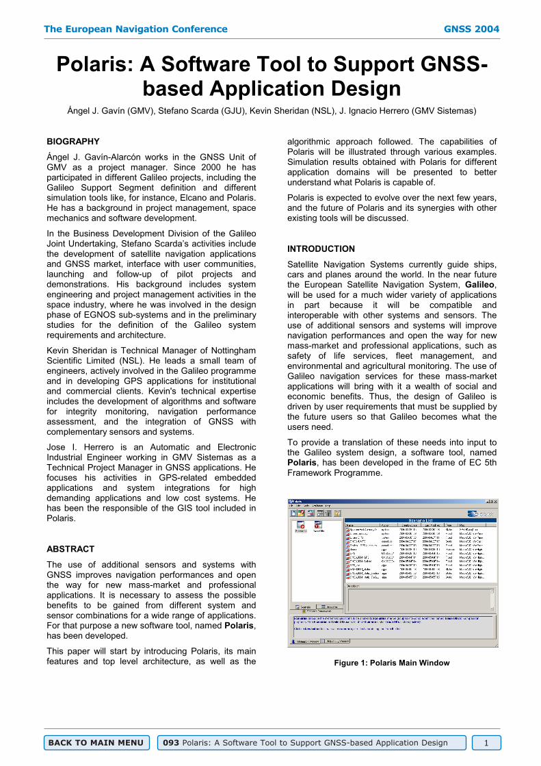
To provide a translation of these needs into input to the Galileo system design, a software tool, named Polaris, has been developed in the frame of EC 5th Framework Programme.
Figure 1: Polaris Main Window
The European Navigation Conference GNSS 2004
BACK TO MAIN MENU 093 Polaris: A Software Tool to Support GNSS-based Application Design 1
The objective of Polaris is to provide the tool needed in order to feed back requirements to the system and application design from a user point of view, and to support the market analysts in obtaining reliable inputs from users and service providers. Taking this into consideration, Polaris has been designed to allow rapid performance assessments of navigation systems and sensors in low-cost platforms to support application and system design.
Therefore, what Polaris actually does is evaluate a given set of navigation performances for a combination of navigation systems and sensors for certain (given) user environments. In doing so, Polaris supports system and application design.
Rapid means that simulations will run “as fast as possible”. Considering that Polaris runs in low cost platforms, i.e., standard PCs and laptops, simulation execution may take only a few seconds (trajectories) or minutes (service areas). Execution time depends mainly on the number of user locations or trajectories to be evaluated, number of satellite failures, etc.
Polaris is not limited to providing feedback to system design. In fact, one of the most interesting uses of Polaris is to support application design.Navigation service providers can use Polaris to estimate application performances and make trade-offs between different implementations. For instance, for a given application, does GPS suffice? Is it necessary to add distance and heading sensors? What about using EGNOS? And DGPS? What will be the situation with Galileo added? These, and other, questions can be answered by evaluating the navigation performances obtained for the application in question.
Market analysts should benefit from Polaris too. By translating application performances into user-friendly and easy-to-understand figures, maps, plots, etc., they can get valuable feedback from potential users, who normally will not have a background in navigation.
Despite the fact that Polaris is primarily focused on simulating mass-market applications, it can still be used as a Service Volume Simulator in system design activities. For instance GNSS engineers can use Polaris to analyse the impact of the different error budget contributions (orbit determination, time synchronisation, ionospheric and tropospheric delays) on navigation performances. User receiver manufacturers can use Polaris in order to allocate margins for receiver noise and multipath figures to support GNSS receiver design. GIS cartography vendors may use Polaris to investigate the accuracy of future navigation systems and thus decide on the accuracy of the maps they have to produce.
Moreover, Polaris can be used to promote the use of Galileo, and to demonstrate the benefits to be
gained from a combined Galileo/GPS based navigation system. There are many pilot projectsaimed at demonstrating the benefits of satellite navigation in different applications. Obviously they can only make use of GPS, or GPS plus wide and local area augmentations as a maximum. Using Polaris it is possible to, first of all, evaluate those applications using GPS, or GPS plus augmentations, and compare the results with real data to gain confidence in the simulation results. Then it is straightforward to simulate the same applications with Galileo in order to demonstrate the benefits to be gained from the use of Galileo. It is also possible to extrapolate to other regions of the world, since it can be impractical to run the same demonstrations in many places. In a similar way, it is also possible to evaluate applications with different user terminal characteristics (GNSS receivers, sensor quality, etc.), ground infrastructure (number and distribution of DGNSS stations, pseudolites, etc.), allowing savings in costly demonstration equipment.
In general, anyone with an interest in navigation performances (e.g. research institutes, e-learning,etc.) is a Polaris potential user.
Polaris has been developed by an international consortium lead by GMV (Spain), in partnership with Galileo Industries, the University of Nottingham (UK), GMV Sistemas (Spain), Edisoft (Portugal) and Tele Atlas (Netherlands).
POLARIS DESCRIPTION
Polaris is mainly focused on mass-market application systems and sensors. Applications being evaluated can include not only GNSS systems, but also regional and local augmentations (SBAS, DGNSS,pseudolites and GSM/GPRS/UMTS positioning) and sensors (odometers, gyroscopes, etc.). About 300 hundred different combinations can be evaluated. Table 1 shows the possible combinations of systems that can be used in Polaris. In addition, Polaris is able to simulate systems like SISNeT, which provides SBAS differential corrections through a wireless network in real time.
NAV. SYSTEM COMBINATIONS GNSS
SBAS
DGNSS
PLs UMTS
Table 1: Combinations of Systems allowed
The sensors that can be used depend upon the application domain to be analysed. The following combinations are allowed:
Road:
The European Navigation Conference GNSS 2004
BACK TO MAIN MENU 093 Polaris: A Software Tool to Support GNSS-based Application Design 2

Odometer + gyroscope Differential odometer Odometer + compass
Pedestrian: Pedometer + Magnetic Compass Pedometer + Gyroscope
Railway: Odometer + Gyrocompass Odometer + Gyrocompass + Balises
Maritime: Speed log + Digital Compass Speed log + Gyrocompass
First of all, it is necessary to select the combination of systems and sensors for the application or system to be evaluated, as well as the user environment and location where the application will be assessed. Since a significant number of applications take place in urban areas, where masking angle conditions affect navigation performances, the option of simulating 3D environments is a must.
Regarding the Figures Of Merit (FOM) to be computed for evaluating an application, Polaris supports the following analyses:
Accuracy (horizontal, vertical, cross-track, long-track, etc.), DOP and number of satellites in view at given availability levels
Availability and continuity risk of accuracy, DOP and number of satellites in view.
Other statistics like, for instance, the percentage of time with GNSS outages, with and without a navigation solution, etc.
The FOM available for a given scenario depend on the application domain. It is also very important to notice that Polaris allows the assessment of navigation performances also for the case of satellitefailures.
Considering that Polaris users (from GNSS engineers to market analysts) have very different levels of expertise on navigation, Polaris includes a user friendly Man Machine Interface (MMI) to assist users in the definition of systems and applications, the FOM to be computed and visualisation of simulation results. Figure 2 shows a Polaris MMI screenshot (visualisation window).
Many Polaris users are interested in evaluating their systems and application in real environments. To do so, the definition of user locations and ground entities is done using a GIS tool fully integrated in the MMI. Users can work with real environments provided that they have a GIS map of the area of interest. Figure 12 shows the definition of a user trajectory in Polaris with the GIS tool.
In addition to generating user locations (service areas or trajectories) the GIS is also used to:
Visualise simulation results in 2D colour maps (see Figure 2)
Define ground entity locations (reference stations, pseudolites, UMTS antennae, etc.)
Figure 2: Polaris Visualisation Window
The use of 3D GIS data may not be justified, nor critical, in some cases given the average expense of such maps, such as when evaluating an application in a typical urban environment. For those situations, Polaris includes a tool to recreate 3D environments starting from 2D GIS maps. Figure 3 shows a screenshot of the 3D Environments Tool (3DET)recreating an urban environment. In the figure, the original 2D map appears on the left and the 3D Polaris creation on the right.
Figure 3: The 3D Environments Tool
All these elements (MMI, GIS and 3DET) work together to build scenarios and simulations. It is a different subsystem, the GNSS and User Application Subsystem (GNSS+UA), which is actually in charge of simulating the applications and providing the selected Figures Of Merit. It is worth mentioning the fact that there is no interaction between the GNSS+UA subsystem and the MMI, GIS
The European Navigation Conference GNSS 2004
BACK TO MAIN MENU 093 Polaris: A Software Tool to Support GNSS-based Application Design 3
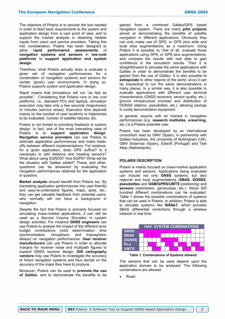
or 3DET during simulation run. All the information required (like, for instance, visibility conditions) is generated “off-line” before the simulation is run. The Core subsystem gathers all the information and passes it to the GNSS+UA, which computes the FOM and generates simulation results files. Figure 4 illustrates this situation.
MMI GIS 3DET
Scenario+
Sim. Conditions
GNSS+UA
Core
MMI GIS 3DET
Scenario+
Sim. Conditions
GNSS+UA
Core
Figure 4: Polaris Top Level Architecture
This approach has a clear benefit. Users may define their environments (service areas/trajectories + visibility conditions), GNSS systems, etc., without relying on the Polaris MMI, which simplifies the process of interfacing Polaris with other tools, moreover, all input and output files are in the XML format.
Polaris follows a “database-like“ logic of use as illustrated in Figure 5. Applications are defined within scenarios. Simulations consist of the scenario definition, plus the FOM to be computed and simulation conditions (time span, time step, satellite failures, etc.) Scenarios are built from ScenarioComponents (built-in or user defined). Scenario components include GNSS and SBAS systems, local elements, user receivers and sensors.
Figure 5: Polaris Logic Workflow
ALGORITHMIC APPROACH
The core of Polaris is a service volume simulator that computes a range of statistical parameters describing the performance of a given constellation of GNSS satellites. It replicates part of the least squares positioning solution that is carried out in a GNSS receiver. Instead of taking range measurements as an input, it considers the errors that would be present in those ranges. These error budgets, together with the defined positions of GNSS satellites, are used to construct a covariance matrix, which describes the precision of the estimated parameters (user position and clock offset). This covariance matrix is used as the basis of the performance analysis, allowing such parameters as DOP and co-ordinate accuracy to be evaluated.
This analysis is carried out at a single point in space and at a single epoch in time. To assess the performance over a selected coverage area and time period, the area of interest is divided into a number of grid points, and the performance at each grid point is assessed at regular intervals throughout the selected time period. Spatial and temporal statistics are then derived from the raw performance data at each grid point. The performance of a GNSS receiver travelling along a specific trajectory is assessed by computing the receiver's co-ordinates at regular intervals along the trajectory, and calling the assessment routines at those points.
In Polaris, GPS, Galileo and GLONASS constellations are defined in terms of satellite positions and the error budget for range measurements. The error budget varies depending on satellite elevation and the selected operating conditions. 3-D models are used to identify the satellite signals that would be received at any user location.
GNSS augmentation systems, such as local ground based augmentation systems (GBAS) or regional space based augmentation systems (SBAS), such as EGNOS, provide correction data to remove or reduce some of the error components of a GNSS ranging signal. The GBAS and SBAS models in Polaris, both apply reductions to individual components of the basic GNSS error budget based on the user’s location relative to reference stations. In the case of SBAS, each GEO satellite also provides an additional ranging signal.
The use of Pseudolites and GSM/UMTS positioning are simulated in Polaris by adding extra ranges, with appropriate error budgets, to the GNSS positioning solution. If enough ranges are provided by either of these systems, they can also provide a completely independent position solution, i.e. without any signals from space.
The performance of GNSS services and additional systems which reduce the errors in satellite ranges,
The European Navigation Conference GNSS 2004
BACK TO MAIN MENU 093 Polaris: A Software Tool to Support GNSS-based Application Design 4

provide additional range measurements, or both, is evaluated on a single epoch basis to produce a covariance matrix of the estimated user position. This is described in Figure 6 as “extended” GNSS processing.
“Extended” GNSS ProcessingSnapshot solution
GNSS,Augmentations,
Ranging Systems
Other configuration
parameters
Result Analysis, Comparison and
Visualisation
Filter?
GNSS Only
GNSS + sensors
Filter Module
No Yes
Scenario Definition
Simulation Execution
Visualisation & Analysis
“Extended” GNSS ProcessingSnapshot solution
GNSS,Augmentations,
Ranging Systems
Other configuration
parameters
Result Analysis, Comparison and
Visualisation
Filter?
GNSS Only
GNSS + sensors
Filter Module
No Yes
Scenario Definition
Simulation Execution
Visualisation & Analysis
Figure 6: Overview of Polaris Processing Logic
To simulate realistic navigation systems, Polaris also considers the affect of applying a filter to successive single epoch position estimates. In a GNSS-based navigation system, a Kalman filter would almost invariably be applied. A filter can improve both the accuracy and availability of a navigation solution by exploiting previously recorded information and knowledge of the receiver motion. A filter also provides a means to integrate measurements from a variety of different systems and sensors.
In periods when sufficient ranges are available to compute a GNSS-based position, Polaris estimates the amount by which a typical filter would improve the accuracy of snapshot position estimates. In reality, this level of improvement depends on factors including the predictability of the vehicle motion, the degree of correlation in the measurements, and the effectiveness of the filter design. Polaris assigns values to each of these parameters depending on the scenario being simulated. During GNSS outages, the accuracy of a filtered solution is simulated by continuing to estimate the vehicle position based on the last measured position, speed and heading, and then differencing these position estimates from the corresponding points in the reference trajectory.
Polaris can also estimate the performance of a GNSS-based navigation system combined with complementary sensors in a user terminal. By combining sensors which measure heading and speed, a dead reckoning solution can be applied during GNSS outages. A range of sensors, appropriate to the various application domains, have been characterised in Polaris allowing the user either
to select sensors of a standard grade, or to define their own specifications. As Polaris is focused primarily on GNSS-based solutions, the sensors which are included are typically “bridging” sensors, i.e. they can provide a usable navigation solution during limited periods of GNSS outage. During periods in which a GNSS solution is available it is assumed that GNSS data is used to calibrate dead reckoning sensors and that bridging sensors will not significantly improve upon the filtered GNSS position solution.
EXAMPLES
The examples presented in this section involve systems like Galileo, GPS and EGNOS. The Galileo constellation that has been used consists of 27 MEO satellites (plus three spare satellites, that have no effect on the simulations presented in this paper). The Galileo Open Service single frequency has been used in all the simulations, unless otherwise noted. The GPS system simulated consists of 24 MEO satellites. The GPS Standard Positioning Service (L1) has been used in all the examples. The EGNOS constellation used consists of 3 GEO satellites. EGNOS ranging signals are assumed to be the same accuracy as those of GPS (L1).
The Galileo, GPS and EGNOS constellations and services have been defined according to the most up-to-date information available at the time of writing this paper. The complete description of the input parameters used for the simulations is beyond the scope of this paper.
The navigation performances for an urban vehicle will be analysed using different combinations of systems and sensors. First of all, an urban environment must be created. This has been done using the 3DET using a 2D map of Madrid. Buildings have been assigned random heights ranging within 25 and 35 meters.
Figure 7: Recreating the 3D urban area for the example (3DET screenshot)
Before starting with the assessment of the urban trajectory, we will first analyse the number of GPS
The European Navigation Conference GNSS 2004
BACK TO MAIN MENU 093 Polaris: A Software Tool to Support GNSS-based Application Design 5
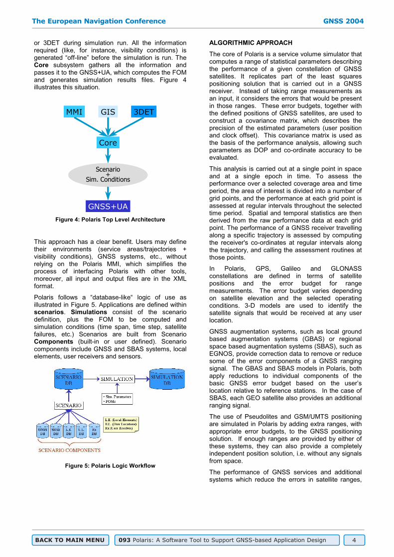
and Galileo satellites in view within the total area in question. It will provide a good understanding of the general situation for the trajectory, since it is independent of the vehicle’s dynamics.
The figures below present the 95% value of the number of satellites in view for the GPS (Figure 8), Galileo (Figure 9) and Galileo + GPS cases (Figure 10). All the maps have been generated with the Polaris GIS tool and, for the sake of clarity, have been represented with a common scale (from 0 to 14 satellites).
Figure 8: Number of GPS Satellites in View (95%)
Figure 9: Number of Galileo Satellites in View (95%)
Figure 10: Number of Galileo+GPS Satellites in View (95%)
As can be seen, the GPS and Galileo cases are fairly similar, but the combined solution makes a clear difference. Figure 11 shows the percentage of user locations with less than 3, exactly 3 and more than 3 satellites in view (95% of the time) for each of the 3 scenarios.
Figure 11: Distribution of the Number of Satellites in View over the Analysed Area
For the GPS case, 63% of the user locations analysed have fewer than 3 satellites in view (95% of the time). For Galileo, the situation is slightly better (48%). The real benefit comes from a combined solution, in which only 15% of the user locations have fewer than 3 satellites in view.
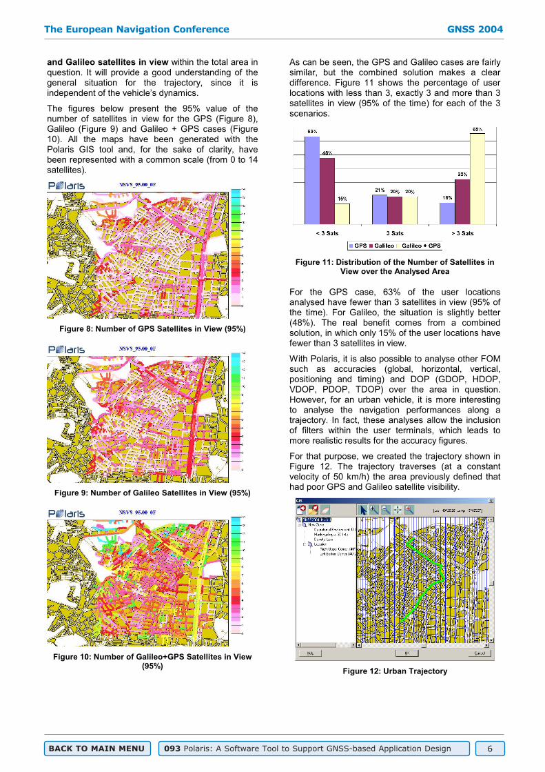
With Polaris, it is also possible to analyse other FOM such as accuracies (global, horizontal, vertical, positioning and timing) and DOP (GDOP, HDOP, VDOP, PDOP, TDOP) over the area in question. However, for an urban vehicle, it is more interesting to analyse the navigation performances along a trajectory. In fact, these analyses allow the inclusion of filters within the user terminals, which leads to more realistic results for the accuracy figures.
For that purpose, we created the trajectory shown in Figure 12. The trajectory traverses (at a constant velocity of 50 km/h) the area previously defined that had poor GPS and Galileo satellite visibility.
Figure 12: Urban Trajectory
The European Navigation Conference GNSS 2004
BACK TO MAIN MENU 093 Polaris: A Software Tool to Support GNSS-based Application Design 6

It takes about 140 seconds for the vehicle to complete the trajectory. Depending on the trajectory start time the satellite positions (with respect to the vehicle’s location) differ, and therefore so do the navigation performances. Therefore it is necessary to evaluate the navigation performances for different time periods and then interpret all of the results. For that purpose, we will evaluate the navigation performances over 3 days, changing the initial epoch by 1 minute for every trajectory assessment (which results in 4320 “trajectory shots”). Table 2 contains the (cumulative) percentage of trajectory shots with horizontal accuracy values (95% of the times) better than given thresholds (4, 6, 8, 10, 15, 20 and 50 meters).
GPS Galileo Gal+GPS
< 4 m 0.0% 0.0% 6.5%
< 6 m 2.8% 9.0% 54.6%
< 8 m 6.5% 21.5% 70.0%
< 10 m 8.2% 25.2% 79.3%
< 15 m 12.4% 33.1% 89.6%
< 20 m 14.5% 36.0% 91.5%
< 50 m 45.3% 58.2% 94.3%
> 50 m 22.8% 21.9% 5.7% HO
RIZ
ON
TA
L A
CC
. (95
%)
NO NAV. SOL. 31.8% 20.0% 0.0%
Table 2: Cumulative Histogram of Trajectory Shots for different Horizontal Accuracy (95%) Thresholds
As it can be clearly seen, Galileo is slightly better than GPS. For instance, the 95th percentile of the horizontal accuracy values (along the trajectory) will be better than 10 meters 8.2% of the time that the journey is made using GPS. For Galileo this percentage is 25.2%, which represents a significant improvement. For the combined solution of Galileo + GPS, this will occur 79.3% of the time. Figure 13 represents graphically the values in Table 2.
Figure 13: Graphical Representation of Cumulative Histogram in Table 2
Polaris provides, for each scenario, the best and worst values for all of the FOM computed (which may occur during different trajectory shots), as well as a “typical trajectory” by selecting a shot that returns “typical” navigation performances. Since the different worst, typical, and best performances are achieved during different epochs for the 3 scenarios, a comparison is not straightforward. In order to accurately compare them, it is necessary to select a single starting epoch (i.e., one trajectory shot).
Applications are often designed for the “worst case” situation. Therefore it seems to be natural to select the worst case situation for, say, GPS horizontal accuracy (95%). However, the analyses show that Galileo alone provides pretty good navigation performances for that situation, and also Galileo + GPS. Vice versa, the worst Galileo case corresponds to a pretty good GPS solution. This is due to the relative phasing between Galileo and GPS satellites. In order to highlight the real benefits of the combined solution, it is necessary to use a different criterion.
The trajectory will be selected according to the percentage of time each GNSS has outages. Taking a look at the statistics for the different trajectory assessments, we identified a situation having GPS outages 53.9% of the time, and Galileo outages 29.8% of the time.
Figure 14: Trajectory Assessments Statistics
In order to assess the trajectory in question, we will evaluate the 95th and 50th percentile values of accuracy (horizontal), DOP (horizontal) and number of satellites in view for the different scenarios.
Num. Sats HACC (m) HDOP
50% 95% 50% 95% 50% 95%
GPS 2 2 10.8 853
����������������������
��������
��������
����������������������
��������
��������
Galileo 3 2 7.7 47.6 3.9
���������������������������������
������������
������������
Galileo+GPS 5 4 5.0 6.7 2.6 3.4
Table 3: Number of Satellites in View, Horizontal Accuracy and HDOP values
The European Navigation Conference GNSS 2004
BACK TO MAIN MENU 093 Polaris: A Software Tool to Support GNSS-based Application Design 7
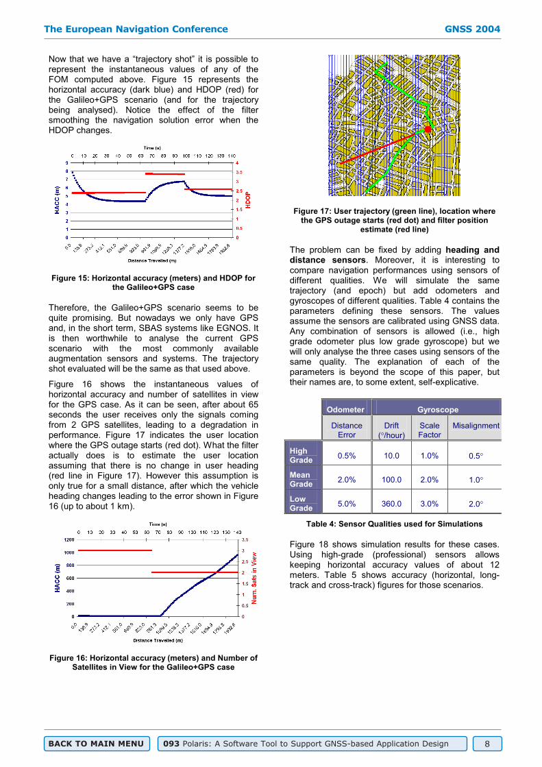
Now that we have a “trajectory shot” it is possible to represent the instantaneous values of any of the FOM computed above. Figure 15 represents the horizontal accuracy (dark blue) and HDOP (red) for the Galileo+GPS scenario (and for the trajectory being analysed). Notice the effect of the filter smoothing the navigation solution error when the HDOP changes.
Figure 15: Horizontal accuracy (meters) and HDOP for the Galileo+GPS case
Therefore, the Galileo+GPS scenario seems to be quite promising. But nowadays we only have GPS and, in the short term, SBAS systems like EGNOS. It is then worthwhile to analyse the current GPS scenario with the most commonly available augmentation sensors and systems. The trajectory shot evaluated will be the same as that used above.
Figure 16 shows the instantaneous values of horizontal accuracy and number of satellites in view for the GPS case. As it can be seen, after about 65 seconds the user receives only the signals coming from 2 GPS satellites, leading to a degradation in performance. Figure 17 indicates the user location where the GPS outage starts (red dot). What the filter actually does is to estimate the user location assuming that there is no change in user heading (red line in Figure 17). However this assumption is only true for a small distance, after which the vehicle heading changes leading to the error shown in Figure 16 (up to about 1 km).
Figure 16: Horizontal accuracy (meters) and Number of Satellites in View for the Galileo+GPS case
Figure 17: User trajectory (green line), location where the GPS outage starts (red dot) and filter position
estimate (red line)
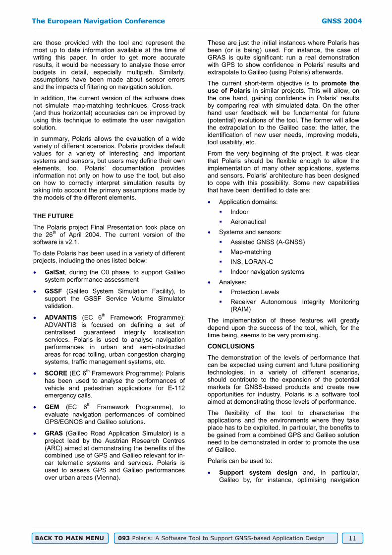
The problem can be fixed by adding heading and distance sensors. Moreover, it is interesting to compare navigation performances using sensors of different qualities. We will simulate the same trajectory (and epoch) but add odometers and gyroscopes of different qualities. Table 4 contains the parameters defining these sensors. The values assume the sensors are calibrated using GNSS data. Any combination of sensors is allowed (i.e., high grade odometer plus low grade gyroscope) but we will only analyse the three cases using sensors of the same quality. The explanation of each of the parameters is beyond the scope of this paper, but their names are, to some extent, self-explicative.
Odometer Gyroscope
Distance Error
Drift( /hour)
Scale Factor
Misalignment
HighGrade 0.5% 10.0 1.0% 0.5
MeanGrade 2.0% 100.0 2.0% 1.0
Low Grade 5.0% 360.0 3.0% 2.0
Table 4: Sensor Qualities used for Simulations
Figure 18 shows simulation results for these cases. Using high-grade (professional) sensors allows keeping horizontal accuracy values of about 12 meters. Table 5 shows accuracy (horizontal, long-track and cross-track) figures for those scenarios.
The European Navigation Conference GNSS 2004
BACK TO MAIN MENU 093 Polaris: A Software Tool to Support GNSS-based Application Design 8
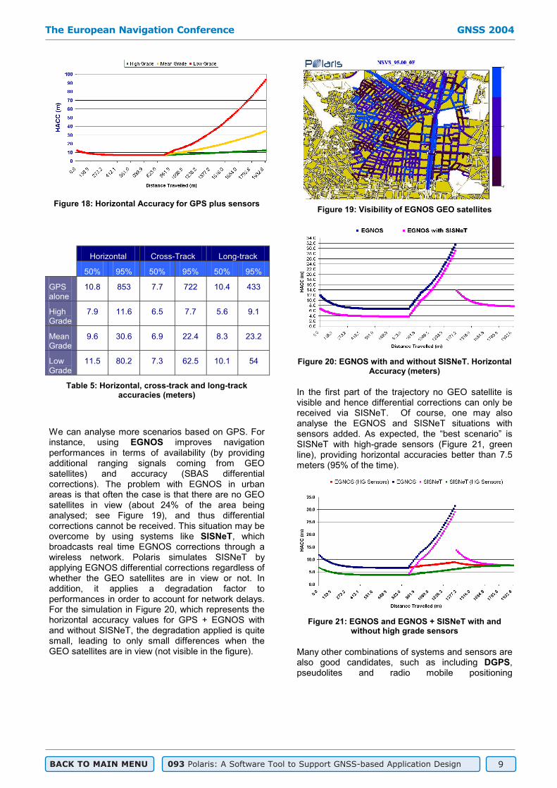
Figure 18: Horizontal Accuracy for GPS plus sensors
Horizontal Cross-Track Long-track
50% 95% 50% 95% 50% 95%
GPSalone
10.8 853 7.7 722 10.4 433
High Grade
7.9 11.6 6.5 7.7 5.6 9.1
Mean Grade
9.6 30.6 6.9 22.4 8.3 23.2
Low Grade
11.5 80.2 7.3 62.5 10.1 54
Table 5: Horizontal, cross-track and long-track accuracies (meters)
We can analyse more scenarios based on GPS. For instance, using EGNOS improves navigation performances in terms of availability (by providing additional ranging signals coming from GEO satellites) and accuracy (SBAS differential corrections). The problem with EGNOS in urban areas is that often the case is that there are no GEO satellites in view (about 24% of the area being analysed; see Figure 19), and thus differential corrections cannot be received. This situation may be overcome by using systems like SISNeT, which broadcasts real time EGNOS corrections through a wireless network. Polaris simulates SISNeT by applying EGNOS differential corrections regardless of whether the GEO satellites are in view or not. In addition, it applies a degradation factor to performances in order to account for network delays. For the simulation in Figure 20, which represents the horizontal accuracy values for GPS + EGNOS with and without SISNeT, the degradation applied is quite small, leading to only small differences when the GEO satellites are in view (not visible in the figure).
Figure 19: Visibility of EGNOS GEO satellites
Figure 20: EGNOS with and without SISNeT. Horizontal Accuracy (meters)
In the first part of the trajectory no GEO satellite is visible and hence differential corrections can only be received via SISNeT. Of course, one may also analyse the EGNOS and SISNeT situations with sensors added. As expected, the “best scenario” is SISNeT with high-grade sensors (Figure 21, green line), providing horizontal accuracies better than 7.5 meters (95% of the time).
Figure 21: EGNOS and EGNOS + SISNeT with and without high grade sensors
Many other combinations of systems and sensors are also good candidates, such as including DGPS,pseudolites and radio mobile positioning
The European Navigation Conference GNSS 2004
BACK TO MAIN MENU 093 Polaris: A Software Tool to Support GNSS-based Application Design 9

(GSM/UMTS). We will introduce some of these combinations together with Galileo.
The Galileo + GPS case was presented earlier on in this paper (Table 3 and Figure 15). We can add EGNOS (providing corrections to GPS, not to Galileo) to the scene. Horizontal accuracy values are shown in Figure 22.
Figure 22: Horizontal Accuracy (meters) for Galileo + GPS with and without EGNOS/SISNeT
At the beginning of the trip, there are no GEO satellites in view. This means that Galileo + GPS and Galileo + GPS/EGNOS behave exactly the same, since there are no additional ranging signals and no differential corrections. The use of SISNeT allows the user to apply EGNOS differential corrections, whose effect can be clearly seen from the start. After travelling about 1350 meters there are GEO satellites in view, and Galileo + GPS/EGNOS and Galileo + GPS/SISNeT horizontal accuracies are fairly similar, but the use of additional ranging signals coming from the GEO satellites improves horizontal accuracies with respect to the Galileo + GPS case.
Similar performances can also be achieved by adding a pseudolite within the vicinity of the trajectory. The pseudolite’s simulated range is large enough (5 km) to allow signal reception at all trajectory positions. The pseudolite’s error budget has been defined to be 4 meters. Results are shown in Figure 23. Horizontal accuracy is 5.7 meters 95% of the time (4.1 meters 50%).
Figure 23: Galileo + GPS with and without a pseudolite
It is widely known that local differential corrections provide better performances than regional (i.e., SBAS). Therefore it makes sense to compare the Galileo OS SF, including local differential corrections for both Galileo and GPS (DGNSS). In case of the Galileo OS dual frequency (OS DF) the ionospheric error contribution is much smaller than for the single frequency (OS SF) case, which means that the effect of differential corrections is not so important. At the same time, and despite the fact that the simulated EGNOS system does not provide corrections to Galileo, the use of the Galileo OS DF improves navigation performances significantly.
In order to simulate the DGNSS scenario, a DGNSS station was placed in the vicinity of the trajectory. Results are shown in Figure 24 and Table 6. As expected, the best scenario is Galileo OS SF + GPS with DGNSS, even when using the single frequency service.
Figure 24: Horizontal Accuracy (meters) for different scenarios involving Galileo OS single and dual
frequency
Horizontal Cross-Track Long-track
50% 95% 50% 95% 50% 95%
Without DGNSS
5.0 6.7 3.1 4.7 4.3 6.7
OS
SF
With DGNSS
0.8 0.9 0.4 0.7 0.6 0.9
Without EGNOS
1.8 4.0 1.7 2.5 1.7 3.5
OS
DF
With EGNOS
1.7 2.4 1.3 1.7 1.5 2.2
Table 6: Accuracy Figures (meters) at different availability levels for the scenarios in Figure 24
There are many more scenarios that can be analysed with Polaris (GSM/UMTS, GPS modernisation, etc.), but the previous cases provide a good understanding of the situation.
The simulation results presented should be interpreted carefully. First of all, error budgets used
The European Navigation Conference GNSS 2004
BACK TO MAIN MENU 093 Polaris: A Software Tool to Support GNSS-based Application Design 10
are those provided with the tool and represent the most up to date information available at the time of writing this paper. In order to get more accurate results, it would be necessary to analyse those error budgets in detail, especially multipath. Similarly, assumptions have been made about sensor errors and the impacts of filtering on navigation solution.
In addition, the current version of the software does not simulate map-matching techniques. Cross-track (and thus horizontal) accuracies can be improved by using this technique to estimate the user navigation solution.
In summary, Polaris allows the evaluation of a wide variety of different scenarios. Polaris provides default values for a variety of interesting and important systems and sensors, but users may define their own elements, too. Polaris’ documentation provides information not only on how to use the tool, but also on how to correctly interpret simulation results by taking into account the primary assumptions made by the models of the different elements.
THE FUTURE
The Polaris project Final Presentation took place on the 26th of April 2004. The current version of the software is v2.1.
To date Polaris has been used in a variety of different projects, including the ones listed below:
GalSat, during the C0 phase, to support Galileo system performance assessment
GSSF (Galileo System Simulation Facility), to support the GSSF Service Volume Simulator validation.
ADVANTIS (EC 6th Framework Programme): ADVANTIS is focused on defining a set of centralised guaranteed integrity localisation services. Polaris is used to analyse navigation performances in urban and semi-obstructed areas for road tolling, urban congestion charging systems, traffic management systems, etc.
SCORE (EC 6th Framework Programme): Polaris has been used to analyse the performances of vehicle and pedestrian applications for E-112 emergency calls.
GEM (EC 6th Framework Programme), to evaluate navigation performances of combined GPS/EGNOS and Galileo solutions.
GRAS (Galileo Road Application Simulator) is a project lead by the Austrian Research Centres (ARC) aimed at demonstrating the benefits of the combined use of GPS and Galileo relevant for in-car telematic systems and services. Polaris is used to assess GPS and Galileo performances over urban areas (Vienna).
These are just the initial instances where Polaris has been (or is being) used. For instance, the case of GRAS is quite significant: run a real demonstration with GPS to show confidence in Polaris’ results and extrapolate to Galileo (using Polaris) afterwards.
The current short-term objective is to promote the use of Polaris in similar projects. This will allow, on the one hand, gaining confidence in Polaris’ results by comparing real with simulated data. On the other hand user feedback will be fundamental for future (potential) evolutions of the tool. The former will allow the extrapolation to the Galileo case; the latter, the identification of new user needs, improving models, tool usability, etc.
From the very beginning of the project, it was clear that Polaris should be flexible enough to allow the implementation of many other applications, systems and sensors. Polaris’ architecture has been designed to cope with this possibility. Some new capabilities that have been identified to date are:
Application domains:
Indoor
Aeronautical
Systems and sensors:
Assisted GNSS (A-GNSS)
Map-matching
INS, LORAN-C
Indoor navigation systems
Analyses:
Protection Levels
Receiver Autonomous Integrity Monitoring (RAIM)
The implementation of these features will greatly depend upon the success of the tool, which, for the time being, seems to be very promising.
CONCLUSIONS
The demonstration of the levels of performance that can be expected using current and future positioning technologies, in a variety of different scenarios, should contribute to the expansion of the potential markets for GNSS-based products and create new opportunities for industry. Polaris is a software tool aimed at demonstrating those levels of performance.
The flexibility of the tool to characterise the applications and the environments where they take place has to be exploited. In particular, the benefits to be gained from a combined GPS and Galileo solution need to be demonstrated in order to promote the use of Galileo.
Polaris can be used to:
Support system design and, in particular, Galileo by, for instance, optimising navigation
The European Navigation Conference GNSS 2004
BACK TO MAIN MENU 093 Polaris: A Software Tool to Support GNSS-based Application Design 11

services. Polaris provides a translation of user’s needs into input to the Galileo system design.
Support application design (dimension ground infrastructure, systems to be used, sensor quality, etc.)
Support Pilot Projects to demonstrate the benefits of satellite navigation, by extrapolatingresults for future systems, like Galileo, and extrapolating to other regions, quality of sensors, etc.
Support market analysis, by providing an easy translation of application performances into user-friendly easy-to-understand figures, maps, plots, etc.
Promote the use of Galileo and EGNOSamong European citizens.
Promote the use of navigation applications
Serve as an e-learning tool to help people understand basic navigation concepts
Although the current version focuses on the assessment of the most significant mass-market applications, Polaris is expected to evolve over the next years to cope with new application domains, systems, sensors and analyses.
Additional information can be found at Polaris web site [1].
ACKNOWLEDGMENTS
The authors want to thank the Galileo Joint Undertaking (GJU), who has been in charge of the technical follow up of the project. Their support and ideas have been of invaluable help for the success of the Polaris project.
Polaris has been designed and implemented by GMV, the University of Nottingham, GMV Sistemas, Edisoft, Galileo Industries and Tele Atlas. GMV has been the project coordinator, and designed and implemented the Polaris MMI, Core and GNSS+UA subsystems. The University of Nottingham was in charge of the user application and sensor modelling. GMV Sistemas implemented the GIS tool. Edisoftimplemented the 3D Environments Tool. Tele Atlasprovided the GIS cartography used in Polaris. Galileo Industries was in charge of the assessment and analysis of the tool.
REFERENCES
[1] Polaris web site: www.polarisGMV.com
[2] A. Gavín et al. Polaris: A Software Tool To Evaluate Navigation Systems Performances. 5th
Geomatic Week (Barcelona, 2003)
[3] Stephen, J. and G. Lachapelle. Development and Testing of a GPS-Augmented Multi-Sensor Vehicle
Navigation System. The Journal of Navigation, Vol. 54, No. 2, May 2001, pp297-319.
[4] Foss, M. and G. J. Geier. Integration of GPS with other Sensors. In Understanding GPS Principles and Applications, Editor E. D. Kaplan. ISBN 0-89006-793-7.
[5] Global Positioning System: Theory & Applications.Parkinson & Spilker. ISBN 1-56347-106-X
[6] Hein G, Eissfeller B, Oehler V and Winkel Jon O. Synergies Between Satellite Navigation and Location services of Terrestrial Mobile Communication. Proc. ION GPS 2000 Sept 2000
[7] RIPA 2 – Ranging and Integrity Pseudolite Augmentations, Thales ATM, IfEN. RIPA-AS-SP-T017 21/06/02 (public domain)
The European Navigation Conference GNSS 2004
BACK TO MAIN MENU 093 Polaris: A Software Tool to Support GNSS-based Application Design 12