polar coding with crc-aided list decoding › dtic › tr › fulltext › u2 › a625869.pdfaided...
TRANSCRIPT

TECHNICAL REPORT 2087 August 2015
Polar Coding with CRC-Aided List Decoding
David Wasserman
Approved for public release.
SSC Pacific San Diego, CA 92152-5001

TECHNICAL REPORT 2087 August 2015
Polar Coding with CRC-Aided List Decoding
David Wasserman
Approved for public release.
SSC Pacific San Diego, CA 92152-5001

SB
SSC Pacific San Diego, California 92152-5001
K. J. Rothenhaus, CAPT, USN Commanding Officer
C. A. Keeney Executive Director
ADMINISTRATIVE INFORMATION The work described in this report was performed by the Space Systems Branch (Code 56270) of the
ISR Division (Code 56200), Space and Naval Warfare Systems Center Pacific (SSC Pacific), San Diego, CA. The Naval Innovative Science and Engineering (NISE) Program at SSC Pacific funded this Applied Research project.
.
ACKNOWLEDGEMENT
The author would like to thank James Wagner, who did some of the work described in this report. This is work of the United States Government and therefore is not copyrighted. This work may be
copied and disseminated without restriction. The citation of trade names and names of manufacturers in this publication is not to construed as
official government endorsement or approval of commercial products or services referenced herein.
Intel® is a registered trademark of Intel Corporation.
Released by A. M. Mroczek, Head Space Systems Branch
Under authority of C. A. Wilgenbusch, Head ISR Division

EXECUTIVE SUMMARY
This report describes some results of the project “More reliable wireless communications through po-lar codes,” funded in fiscal year 2015 by the Naval Innovative Science and Engineering (NISE) program atSSC Pacific.
OBJECTIVE
The purpose of the project is to determine if polar codes can outperform the forward error correction(FEC) currently used in Navy wireless communication systems. The project team has implemented an ad-vanced decoding method called cyclic redundancy check (CRC)-aided list decoding.
RESULTS
Our simulation results show that polar coding can produce results very similar to the FEC used in theDigital Video Broadcasting - Satellite - Second Generation (DVB-S2) standard, and can provide up to 15percent higher throughput by using code rates not provided in the DVB-S2 standard.
RECOMMENDATIONS
In any application for which the DVB-S2 FEC is considered, polar coding with CRC-aided list decod-ing with N = 65536 should also be considered.
iv

CONTENTS
EXECUTIVE SUMMARY ..................................................................................................................... iii
1. INTRODUCTION............................................................................................................................. 1
2. POLAR CODING ............................................................................................................................ 2
2.1 SYSTEMATIC POLAR CODING ......................................................................................... 2
3. LIST DECODING ............................................................................................................................ 3
3.1 CRC-AIDED LIST DECODING............................................................................................ 5
4. PARAMETERS OF THE SIMULATIONS..................................................................................... 6
4.1 THE CHANNEL ..................................................................................................................... 6
4.2 THE POLAR CODE .............................................................................................................. 6
4.3 THE CRC................................................................................................................................ 6
4.4 THE DECODER..................................................................................................................... 7
4.5 SUMMARY OF PARAMETERS VARIED ............................................................................ 7
5. RESULTS......................................................................................................................................... 8
5.1 EFFECT OF VARYING LIST SIZE ...................................................................................... 8
5.2 EFFECT OF VARYING BLOCK SIZE ................................................................................. 9
5.3 EFFECT OF VARYING CODE RATE.................................................................................. 9
5.4 EFFECT OF VARYING CRC POLYNOMIAL...................................................................... 11
5.5 EFFECT OF VARYING CRC LENGTH............................................................................... 125.5.1 Preliminary Test ........................................................................................................... 135.5.2 Baseline Test ................................................................................................................ 145.5.3 Test With a Different List Size .................................................................................... 155.5.4 Test With a Different Code Rate ................................................................................ 155.5.5 Test With a Different Block Size................................................................................. 165.5.6 Test With a Different Target BER ............................................................................... 175.5.7 CRC Length Summary................................................................................................ 17
5.6 EFFECT OF VARYING CODE DESIGN Es/N0 ................................................................ 17
6. IMPLEMENTATION DETAILS....................................................................................................... 19
6.1 DECODING SPEED.............................................................................................................. 20
7. CONCLUSION ................................................................................................................................ 21
REFERENCES...................................................................................................................................... 21
Figures
1. SC decoding tree. ........................................................................................................................ 32. List decoding tree with L = 4...................................................................................................... 43. BER vs. Eb/N0 for N = 2048, rate = 1/2, and varying list sizes. ........................................... 84. BER vs. Eb/N0 for L = 4, rate = 1/2, and varying block sizes................................................ 9
v
5. Eb/N0 needed to achieve BER = 10−5 for various block sizes and code rates. ................... 106. Es/N0 needed to achieve BER = 10−5 for various block sizes and code rates .................... 117. Comparison of 16-bit CRCs with list size 4. ............................................................................. 128. Comparison of 16-bit CRCs with list size 32. ........................................................................... 129. Comparison of CRC lengths with N = 2048, K = 1040, and list size 4. ............................... 1310. Comparison of CRC lengths with N = 2048, r = 1/2, and list size 4. ................................... 1411. Comparison of CRC lengths with N = 2048, r = 1/2, and list size 32.................................. 1512. Comparison of CRC lengths with N = 2048, r = 0.7, and list size 4..................................... 1613. Comparison of CRC lengths with N = 32768, r = 1/2, and list size 8.................................. 1614. Comparison of CRC lengths with N = 2048, r = 1/2, and list size 4. ................................... 1715. Comparison of design Es/N0’s with N = 2048, r = 1/2, 16 bit CRC, and list size 4........... 18
Tables
1. CRC polynomials tested. ............................................................................................................ 13
vi
1. INTRODUCTION
Polar codes are a new type of forward error correction (FEC) codes, introduced by Arikan in [1], inwhich he proved that they can achieve the capacity of any binary memoryless symmetric channel with effi-cient encoding and decoding.
In fiscal years (FY) 2014 and 2015, SSC Pacific’s Naval Innovative Science and Engineering (NISE)program funded the project “More Reliable Wireless Communications Through Polar Codes” to studypolar codes and determine if they can outperform the forward error correction (FEC) currently used inNavy wireless communication systems. The project’s FY 2014 results are described in [2]. In FY 2015the project team has implemented an advanced decoding method called cyclic redundancy check (CRC)-aided list decoding, and simulated its performance in a wide variety of cases. This report documents theresults of those simulations. The project’s other FY 2015 work will be published separately.
Section 2 describes the basics of polar coding. CRC-aided list decoding is described in Section 3. Sec-tion 4 describes the scope of our study, and Section 5 presents the results. Section 6 gives details of howwe implemented the decoder. Finally, Section 7 concludes the report.
1

2. POLAR CODING
Several versions of polar coding have been published. This section is intended to indicate which ver-sion is used in this work. For background and motivation of this material, see our previous technical report[2].
For any n > 0, we can specify a polar code of length N = 2n by choosing a subset A ⊂ {1, . . . , N}.If A has K elements, we get an (N,K) block code. A must be chosen well for good error-correction per-formance. We used the method of [3].
The polar encoder uses a row vector u of length N . Let uA be the subvector containing elementswhose indices are in A, and let uAC be the subvector containing the remaining N −K elements of u. Theencoder constructs u by filling uA with K information bits, and setting uAC to predetermined values, usu-ally all 0’s. These predetermined values are called frozen bits. The encoder outputs x = uGN where GN
is the N by N matrix F⊗nΠN , where F =
[1 01 1
], F⊗n is its nth tensor power, and ΠN is a permutation
matrix called the bit-reversal operator, defined in Section VII of [1]. This encoder can be implementedwith complexity O(N logN).
Arikan showed in [1] that polar codes can achieve capacity using a successive cancellation (SC) de-coder. This decoder computes estimates u1, . . . , uN , one at a time, in order, with complexity O(N logN).
2.1 SYSTEMATIC POLAR CODING
Systematic polar coding was introduced in [4]. The systematic polar encoder also computes x =uF⊗nΠN , but the information bits are found in x rather than in u. Specifically, [4] showed that for anyvector of K information bits, there is a unique u such that uAC is all 0’s and wA is the specified informa-tion bits, where w = uF⊗n.
The systematic SC decoder computes the estimate u in the same way as the non-systematic decoder,and also computes w = uF⊗n. Then wA is the desired estimate of the information bits.
Arikan proved in [4] that systematic polar coding has the same frame error rate (FER)1 as non-systematicpolar coding. Arikan also provided simulation results showing that systematic polar coding has a lower biterror rate (BER) than non-systematic. This result has been replicated, but to our knowledge it has neverbeen proven.
1Also known as block error rate.
2
3. LIST DECODING
Recall from Section 2 that the SC decoder estimates u1, . . . , uN , one at a time, in order. For conve-nience, we introduce some non-standard notation. For any k ≤ N and any sequence of bits b1, b2, . . . , bk,let P (b1, b2, . . . , bk) be the decoder’s estimate of the probability that u begins with (b1, b2, . . . , bk).P (b1, b2, . . . , bk) depends on the decoder’s input, but to make the notation simpler we do not include thedecoder’s input in the expression.2
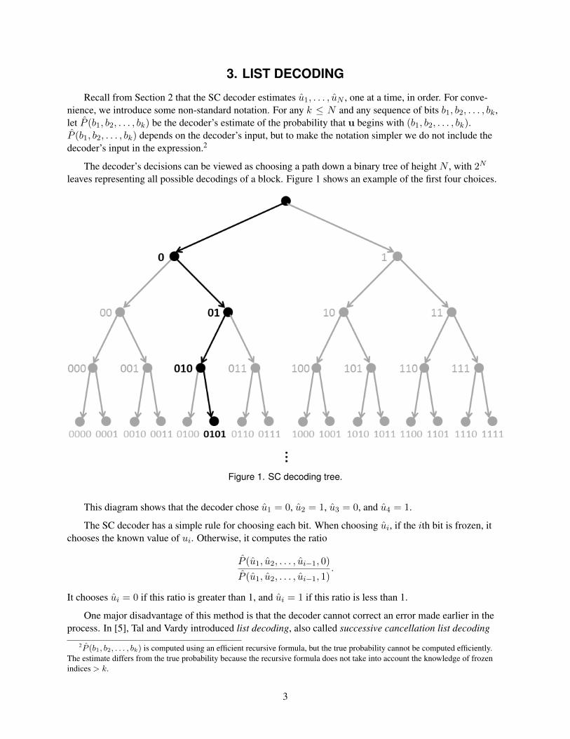
The decoder’s decisions can be viewed as choosing a path down a binary tree of height N , with 2N
leaves representing all possible decodings of a block. Figure 1 shows an example of the first four choices.
Figure 1. SC decoding tree.
This diagram shows that the decoder chose u1 = 0, u2 = 1, u3 = 0, and u4 = 1.
The SC decoder has a simple rule for choosing each bit. When choosing ui, if the ith bit is frozen, itchooses the known value of ui. Otherwise, it computes the ratio
P (u1, u2, . . . , ui−1, 0)
P (u1, u2, . . . , ui−1, 1).
It chooses ui = 0 if this ratio is greater than 1, and ui = 1 if this ratio is less than 1.
One major disadvantage of this method is that the decoder cannot correct an error made earlier in theprocess. In [5], Tal and Vardy introduced list decoding, also called successive cancellation list decoding
2P (b1, b2, . . . , bk) is computed using an efficient recursive formula, but the true probability cannot be computed efficiently.The estimate differs from the true probability because the recursive formula does not take into account the knowledge of frozenindices > k.
3

(SCL), to mitigate this problem. They found that list decoder’s error correction performance was signifi-cantly better than SC, at the cost of higher computational complexity.
The list decoder follows multiple paths down the decoding tree. Figure 2 shows an example of a listdecoder estimating u1 through u4.
Figure 2. List decoding tree with L = 4.
For convenience, assume that none of the first four indices are frozen.3 Instead of choosing if u1 is0 or 1, the list decoder chooses both, and likewise for u2. In this way, it generates a list of candidate de-codings. After two steps, the list contains four candidates: (0, 0), (0, 1), (1, 0), and (1, 1). After each non-frozen bit, the number of candidates doubles until it exceeds a predetermined maximum. This maximum iscalled the list size, and is represented by the symbol L.
Figure 2 shows an example with L = 4. In the third step, the decoder computes probability estimatesfor all eight possibilities: P (0, 0, 0), P (0, 0, 1), P (0, 1, 0), P (0, 1, 1), P (1, 0, 0), P (1, 0, 1), P (1, 1, 0),and P (1, 1, 1). It retains in the list the L candidates with the largest probability estimates. In the example,these are (0, 0, 1), (0, 1, 0), (0, 1, 1), and (1, 0, 0).
After the list has been pruned, the decoder does not compute probability estimates for all possibilities,but only the 2L possibilities that are extensions of the candidates in the list. In the example shown in 2, itcomputes P (0, 0, 1, 0), P (0, 0, 1, 1), P (0, 1, 0, 0), P (0, 1, 0, 1), P (0, 1, 1, 0), P (0, 1, 1, 1), P (1, 0, 0, 0),and P (1, 0, 0, 1). Again, the L candidates with the largest probability estimates are maintained in the list.The computational complexity of the list decoder is roughly L times that of an SC decoder.
After N steps, the decoder has a list L candidates that each include N bits, and it has a probability foreach one. It chooses u to be the most probable candidate.
3In most practical polar codes, the first four indices are all frozen.
4

Tal and Vardy experimented with list decoding a (2048, 1024) polar code and found that list decodingwith small to moderate list sizes could match the FER of a maximum likelihood decoder.4 The lower theEb/N0, the larger list size is needed: with L = 2 the list decoder matches the maximum likelihood decoderfor Eb/N0 ≥ 2.75 decibels (dB), and with L = 32 it matches for Eb/N0 ≥ 1.75 dB. However, evenwith the improvement caused by list decoding, the error-correction performance of polar codes is poorcompared to turbo and low-density parity check (LDPC) codes.
3.1 CRC-AIDED LIST DECODING
Tal and Vardy [5] found that a slight change could yield even better results, outperforming the LDPCcode used in the WiMax standard. They ran simulations of list decoding and found that when the decoderproduces the wrong answer, often the correct answer is in the list. Therefore, instead of always choosingthe most probable candidate, it would help to be able to pick the correct answer out of this list. The use ofa CRC helps to achieve this goal.
A CRC is an error detection code. It is specified by a binary polynomial of degree d, where d can beany positive integer. The CRC takes as input an information bit vector of any length, and outputs a binaryvector of length d, called the check bits or the parity bits. Both the information bits and the check bits aresent to a receiver. The receiver applies the same CRC to the received information bits, and checks if theresult matches the received check bits. If they do not match, an error has occurred. For a randomly chosenbit vector, the probability of passing the CRC is 1
2d. More details about CRC can be found in [7].
In polar coding with CRC-aided list decoding, we use an (N,K) polar code and a d-bit CRC. We startwith K − d information bits, and use the CRC to compute d check bits. We append the check bits to theinformation bits, and input all K bits to the polar encoder. The encoder outputs N bits, which are sent tothe receiver. At the receiver, the list decoder works as described above until the last step. Instead of simplychoosing the most probable candidate, the decoder uses the CRC to test the candidates for errors. If oneor more candidates pass, the decoder outputs the most probable among those that pass. If none of the can-didates pass, the decoder outputs the most probable candidate, and also outputs a flag indicating that theresult is incorrect.
The price we pay for using CRC is that we have K − d information bits instead of K. We can compen-sate by increasing K. This means we have fewer frozen bits, so the error-correction capability of the polarcode is decreased, but in return we get additional error-correction capability from the CRC. If d is chosenwell, we receive a net gain.
For the rest of this report we will use the symbol Ki for the number of information bits per block. Kwill always be the number of non-frozen bits in a polar code.
4A naive implementation of a maximum likelihood decoder would have to compute the probability of all 2K possibilities. In[6] it was shown that this complexity can be reduced to roughly cubic, but this is still too high to be practical when N = 2048. Taland Vardy did not implement a maximum likelihood decoder, but they did compute a lower bound of its FER and found that thelist decoder came very close to this bound, close enough that the difference is not visible in a graph. The FER of the maximumlikelihood decoder is less that the FER of the list decoder, but greater than the lower bound, so all three of these values are veryclose.
5

4. PARAMETERS OF THE SIMULATIONS
The BER of CRC-aided list decoding depends on several parameters involving the channel, the polarcode, the CRC, and the decoder. The following subsections describe these parameters.
4.1 THE CHANNEL
In this report, the “channel” encompasses everything between the encoder output and the decoder in-put. All channels used in this report are binary-input additive white Gaussian noise (AWGN) channels.Such a channel is determined by a parameter σ. The channel input b can be 0 or 1, and the output is (−1)b+n, where n is a sample from a normal distribution with mean 0 and standard deviation σ. Each time an-other bit is sent, a new n is chosen, and all the n’s are independent.
An AWGN channel can also be described by the ratio of symbol energy (Es) to noise spectral den-sity (N0). We have normalized the energy so that Es = 1 and N0 = 2σ2. We also frequently use theratio Eb/N0 where Eb is the bit energy, or more precisely, the energy per information bit. Thus, Eb/N0 =(Es/N0)/r, where r is the code rate Ki/N . Both Es/N0 and Eb/N0 are usually expressed in decibels.
Most FEC literature uses AWGN channels, so we did also, making it easier for us to compare our re-sults to previous results on polar codes and other FEC.
4.2 THE POLAR CODE
For any N that is a power of 2 and any K < N , an (N,K) polar code can be specified by choosing aK-element subset of {1, . . . , N}.5 This subset is normally chosen to optimize the performance of the codefor a particular channel. We constructed polar codes using the method of Tal and Vardy [3]. All the codesused in this report were optimized for AWGN channels of various Es/N0 values. The Tal/Vardy methodrequires specifying a fidelity parameter µ; we used µ = 512.
The Tal/Vardy method, like most polar code construction methods, is designed to minimize the FER ofan SC decoder. In the process, it computes an upper bound for this FER. In our previous work, we foundthat if µ ≥ 256 and FER ≤ 10−3, then this upper bound is very close to the true FER. In contrast, thereis no method known to predict the performance of a list decoder except running a large number of trials.Thus, a code that is optimal for SC decoding in a given AWGN channel may not be optimal for list decod-ing, and a code designed for a different AWGN channel might perform better.
4.3 THE CRC
The CRC polynomial can be any polynomial with coefficients in {0, 1} such that the constant term is1. The number d of check bits equals the degree of the polynomial. Although d is determined by the poly-nomial, we treated them as two separate parameters: we can compare CRC lengths, or compare differentpolynomials at the same length. It is impossible to compare different lengths at the same polynomial.
5It is also possible to change the code by specifying the N − K frozen bits. We follow the usual convention that all frozen bitsare 0.
6

4.4 THE DECODER
After specifying the above parameters, there are two things left to vary, the list size and the decoder’sknowledge of the channel. When the decoder receives a channel output y, it must compute the likelihoods:if a 0 is transmitted, what is the probability of receiving y? If a 1 is transmitted, what is the probabilityof receiving y? If the decoder knows that the channel is an AWGN channel, and knows the Es/N0 of thechannel, it can compute the correct probabilities. If the decoder uses a channel model that differs from thetrue channel, it will compute different probabilities, which could degrade its performance. In our simula-tions, the decoder always used a channel model that exactly matched the channel.
4.5 SUMMARY OF PARAMETERS VARIED
We varied seven different parameters:
1. The Es/N0 of the AWGN channel ranged from -5.5 to 3.8 dB.
2. The block size N ranged from 512 to 65536.
3. The code rate r = Ki/N ranged from 0.25 to 0.9.
4. The Es/N0 that the code was designed for ranged from 3 dB below to 3 dB above the Es/N0
of the channel.
5. The CRC length d ranged from 4 to 24.
6. The CRC polynomial: we used four different polynomials with d = 16, and one polynomial foreach other length tested. All of these polynomials were taken from [8] or [9].
7. The list size L ranged from 1 to 64. Note that the list size can be any positive integer, but allthe list sizes we have seen in the literature were powers of two. We also have tested only pow-ers of 2.
We specify an FEC system by choosing values for parameters 2 through 7, and we test the system by com-puting the BER as a function of Eb/N0.
Coding theorists typically compare FEC systems by specifying a target BER or FER, and finding theEb/N0 at which each system achieves the target. The difference between two such Eb/N0’s is called cod-ing gain. For most of our tests, we used the target BER = 10−5, because this is the target BER specified insome Department of Defense specifications, such as in Table XVI of [10]. An expert at SSC Pacific told usthat for TCP/IP transmissions, the target BER is 10−8. However, it takes a large number of trials to mea-sure a BER this low, and we could only do this for a few cases.
In practice, N , r, and L must be chosen for the requirements of a particular system because they havea large effect on throughput, delay, and complexity. In contrast, the CRC length, CRC polynomial, andcode design Es/N0 have little effect on throughput, delay, and complexity. Therefore, for any given com-bination of N , r, L, and target BER, there is a best combination of CRC length, CRC polynomial, andcode design Es/N0: the combination that achieves the target BER at the lowest Eb/N0.
7
5. RESULTS
The starting point for our investigation of CRC-aided list decoding was the example shown at the be-ginning of [5]: N = 2048, code rate = 1/2, code design Es/N0 = -1.01 dB, CRC length = 16, and list size= 32. The authors of [5] did not specify what CRC polynomial they used. We started with the polynomialx16 + x15 + x2 + 1, called “CRC-16-IBM” in [8].
Preliminary tests suggested that code design Es/N0 could be varied over a wide range without mucheffect on BER performance. As a result, we were not always careful in choosing the code design Es/N0. 6
5.1 EFFECT OF VARYING LIST SIZE
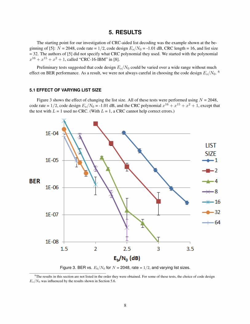
Figure 3 shows the effect of changing the list size. All of these tests were performed using N = 2048,code rate = 1/2, code design Es/N0 = -1.01 dB, and the CRC polynomial x16 + x15 + x2 + 1, except thatthe test with L = 1 used no CRC. (With L = 1, a CRC cannot help correct errors.)
Figure 3. BER vs. Eb/N0 for N = 2048, rate = 1/2, and varying list sizes.
6The results in this section are not listed in the order they were obtained. For some of these tests, the choice of code designEs/N0 was influenced by the results shown in Section 5.6.
8
The figure shows significant improvement as list size is increased from 1 to 4, and rapidly diminishingimprovements as list size is increased further. We chose to use L = 4 for most of our subsequent experi-ments.
5.2 EFFECT OF VARYING BLOCK SIZE
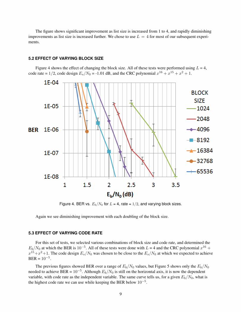
Figure 4 shows the effect of changing the block size. All of these tests were performed using L = 4,code rate = 1/2, code design Es/N0 = -1.01 dB, and the CRC polynomial x16 + x15 + x2 + 1.
Figure 4. BER vs. Eb/N0 for L = 4, rate = 1/2, and varying block sizes.
Again we see diminishing improvement with each doubling of the block size.
5.3 EFFECT OF VARYING CODE RATE
For this set of tests, we selected various combinations of block size and code rate, and determined theEb/N0 at which the BER is 10−5. All of these tests were done with L = 4 and the CRC polynomial x16 +x15+x2+1. The code design Es/N0 was chosen to be close to the Es/N0 at which we expected to achieveBER = 10−5.
The previous figures showed BER over a range of Eb/N0 values, but Figure 5 shows only the Eb/N0
needed to achieve BER = 10−5. Although Eb/N0 is still on the horizontal axis, it is now the dependentvariable, with code rate as the independent variable. The same curve tells us, for a given Eb/N0, what isthe highest code rate we can use while keeping the BER below 10−5.
9
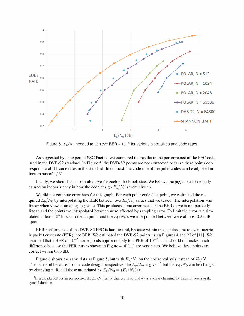
Figure 5. Eb/N0 needed to achieve BER = 10−5 for various block sizes and code rates.
As suggested by an expert at SSC Pacific, we compared the results to the performance of the FEC codeused in the DVB-S2 standard. In Figure 5, the DVB-S2 points are not connected because these points cor-respond to all 11 code rates in the standard. In contrast, the code rate of the polar codes can be adjusted inincrements of 1/N .
Ideally, we should see a smooth curve for each polar block size. We believe the jaggedness is mostlycaused by inconsistency in how the code design Es/N0’s were chosen.
We did not compute error bars for this graph. For each polar code data point, we estimated the re-quired Eb/N0 by interpolating the BER between two Eb/N0 values that we tested. The interpolation waslinear when viewed on a log-log scale. This produces some error because the BER curve is not perfectlylinear, and the points we interpolated between were affected by sampling error. To limit the error, we sim-ulated at least 105 blocks for each point, and the Eb/N0’s we interpolated between were at most 0.25 dBapart.
BER performance of the DVB-S2 FEC is hard to find, because within the standard the relevant metricis packet error rate (PER), not BER. We estimated the DVB-S2 points using Figures 4 and 22 of [11]. Weassumed that a BER of 10−5 corresponds approximately to a PER of 10−3. This should not make muchdifference because the PER curves shown in Figure 4 of [11] are very steep. We believe these points arecorrect within 0.05 dB.
Figure 6 shows the same data as Figure 5, but with Es/N0 on the horizontal axis instead of Eb/N0.This is useful because, from a code design perspective, the Es/N0 is given,7 but the Eb/N0 can be changedby changing r. Recall these are related by Eb/N0 = (Es/N0)/r.
7In a broader RF design perspective, the Es/N0 can be changed in several ways, such as changing the transmit power or thesymbol duration.
10

Figure 6. Es/N0 needed to achieve BER = 10−5 for various block sizes and code rates
The DVB-S2 results form a stairstep curve due to the limited choice of code rates. For example, sup-pose the Es/N0 is -2.1 dB and we are required to maintain BER ≤ 10−5. Using DVB-S2, we can achievea code rate of 0.5. Now suppose the Es/N0 increases to -1.3 dB. This is not high enough to use a higher-rate DVB-S2 code, so a DVB-S2 user would continue to use rate 0.5. In contrast, using a polar code ofapproximately the same length, at -1.3 dB we could use rate 0.54. In the range -2 dB < Es/N0 < -0.9 dB,polar codes of length 65536 can provide up to 15% more throughput than DVB-S2 codes.
5.4 EFFECT OF VARYING CRC POLYNOMIAL
We compared four different polynomials of length 16:
1. The previously mentioned CRC-16-IBM.
2. x16 + x14 + x13 + x12 + x10 + x8 + x6 + x4 + x3 + x1 + 1, from Table 3 of [9]. We refer to thispolynomial as “Koopman”.
3. x16 + x12 + x5 + 1, called “CRC-16-CCITT” in [8].
4. x16 + x15 + x14 + x11 + x6 + x5 + x2 + x1 + 1, called “CRC-16-CDMA2000” in [8].
Figure 7 shows the results of using these four polynomials with N = 2048, r = 1/2, list size 4, and designEs/N0 -1.01 dB. Figure 8 shows the results of using these four polynomials with N = 2048, r = 1/2, listsize 32, and design Es/N0 -1.25 dB. In both cases, the design Es/N0 was chosen to be approximately theEs/N0 at which the BER is 10−5.
11

Figure 7. Comparison of 16-bit CRCs with list size 4.
Figure 8. Comparison of 16-bit CRCs with list size 32.
The effect of changing the polynomial is smaller than the measurement error, and too small to matter.For each of the eight systems tested, we interpolated to find the Eb/N0 at which the BER is 10−5. For bothL = 4 and L = 32, CRC-16-IBM was best, but the difference between best and worst was 0.005 dB and0.013 dB, respectively. We decided it was not necessary to do further comparisons of polynomials with thesame length.
5.5 EFFECT OF VARYING CRC LENGTH
We tested CRC-aided list decoding using the CRC lengths and polynomials shown in Table 1.
As mentioned in Section 4.5, the best CRC length may depend on N , the code rate, the list size, andthe target BER. We ran tests to determine the best length in a few different cases.
12
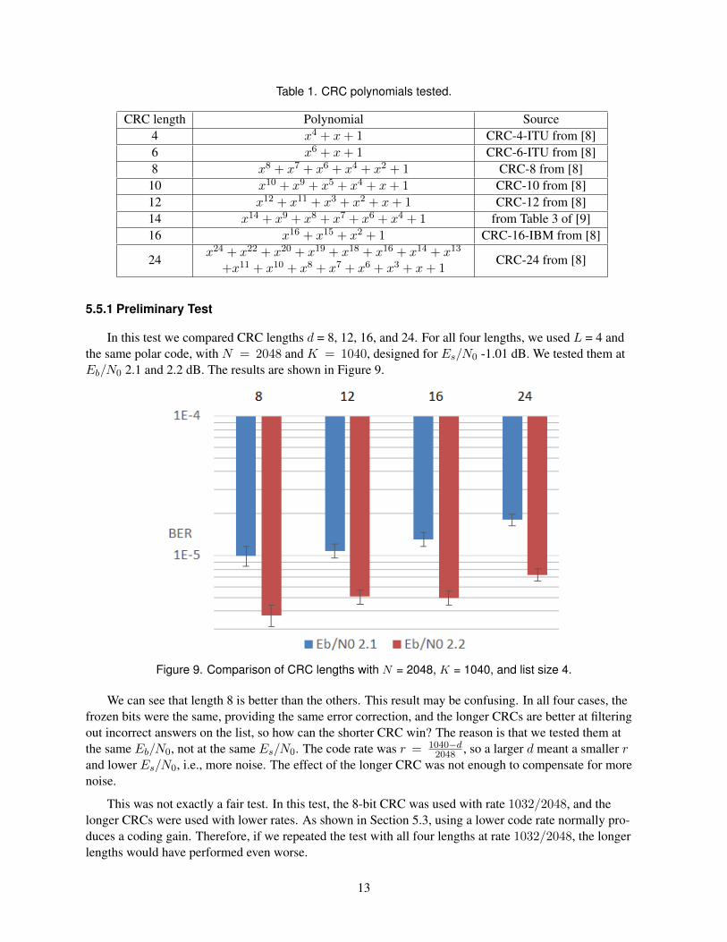
Table 1. CRC polynomials tested.
CRC length Polynomial Source4 x4 + x+ 1 CRC-4-ITU from [8]6 x6 + x+ 1 CRC-6-ITU from [8]8 x8 + x7 + x6 + x4 + x2 + 1 CRC-8 from [8]10 x10 + x9 + x5 + x4 + x+ 1 CRC-10 from [8]12 x12 + x11 + x3 + x2 + x+ 1 CRC-12 from [8]14 x14 + x9 + x8 + x7 + x6 + x4 + 1 from Table 3 of [9]16 x16 + x15 + x2 + 1 CRC-16-IBM from [8]
24x24 + x22 + x20 + x19 + x18 + x16 + x14 + x13
+x11 + x10 + x8 + x7 + x6 + x3 + x+ 1CRC-24 from [8]
5.5.1 Preliminary Test
In this test we compared CRC lengths d = 8, 12, 16, and 24. For all four lengths, we used L = 4 andthe same polar code, with N = 2048 and K = 1040, designed for Es/N0 -1.01 dB. We tested them atEb/N0 2.1 and 2.2 dB. The results are shown in Figure 9.
Figure 9. Comparison of CRC lengths with N = 2048, K = 1040, and list size 4.
We can see that length 8 is better than the others. This result may be confusing. In all four cases, thefrozen bits were the same, providing the same error correction, and the longer CRCs are better at filteringout incorrect answers on the list, so how can the shorter CRC win? The reason is that we tested them atthe same Eb/N0, not at the same Es/N0. The code rate was r = 1040−d
2048 , so a larger d meant a smaller rand lower Es/N0, i.e., more noise. The effect of the longer CRC was not enough to compensate for morenoise.
This was not exactly a fair test. In this test, the 8-bit CRC was used with rate 1032/2048, and thelonger CRCs were used with lower rates. As shown in Section 5.3, using a lower code rate normally pro-duces a coding gain. Therefore, if we repeated the test with all four lengths at rate 1032/2048, the longerlengths would have performed even worse.
13
In subsequent tests, we always compared codes with the same length and rate.
5.5.2 Baseline Test
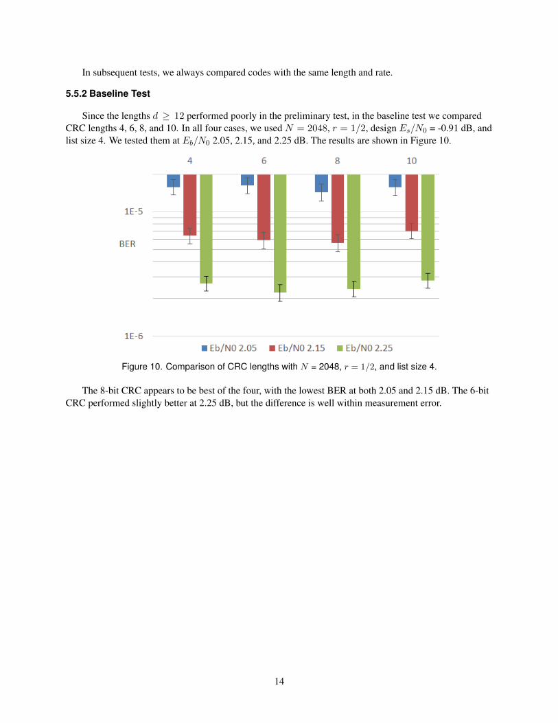
Since the lengths d ≥ 12 performed poorly in the preliminary test, in the baseline test we comparedCRC lengths 4, 6, 8, and 10. In all four cases, we used N = 2048, r = 1/2, design Es/N0 = -0.91 dB, andlist size 4. We tested them at Eb/N0 2.05, 2.15, and 2.25 dB. The results are shown in Figure 10.
Figure 10. Comparison of CRC lengths with N = 2048, r = 1/2, and list size 4.
The 8-bit CRC appears to be best of the four, with the lowest BER at both 2.05 and 2.15 dB. The 6-bitCRC performed slightly better at 2.25 dB, but the difference is well within measurement error.
14
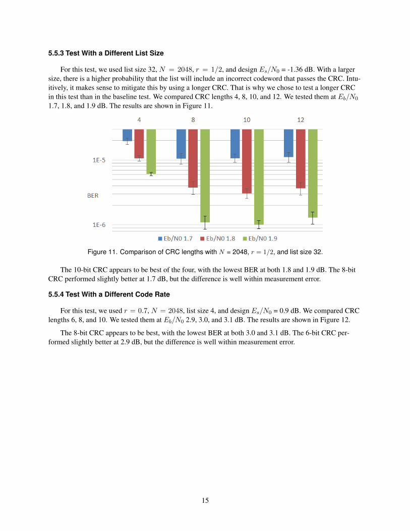
5.5.3 Test With a Different List Size
For this test, we used list size 32, N = 2048, r = 1/2, and design Es/N0 = -1.36 dB. With a largersize, there is a higher probability that the list will include an incorrect codeword that passes the CRC. Intu-itively, it makes sense to mitigate this by using a longer CRC. That is why we chose to test a longer CRCin this test than in the baseline test. We compared CRC lengths 4, 8, 10, and 12. We tested them at Eb/N0
1.7, 1.8, and 1.9 dB. The results are shown in Figure 11.
Figure 11. Comparison of CRC lengths with N = 2048, r = 1/2, and list size 32.
The 10-bit CRC appears to be best of the four, with the lowest BER at both 1.8 and 1.9 dB. The 8-bitCRC performed slightly better at 1.7 dB, but the difference is well within measurement error.
5.5.4 Test With a Different Code Rate
For this test, we used r = 0.7, N = 2048, list size 4, and design Es/N0 = 0.9 dB. We compared CRClengths 6, 8, and 10. We tested them at Eb/N0 2.9, 3.0, and 3.1 dB. The results are shown in Figure 12.
The 8-bit CRC appears to be best, with the lowest BER at both 3.0 and 3.1 dB. The 6-bit CRC per-formed slightly better at 2.9 dB, but the difference is well within measurement error.
15

Figure 12. Comparison of CRC lengths with N = 2048, r = 0.7, and list size 4.
5.5.5 Test With a Different Block Size
For this test, we used N = 32768, r = 1/2, list size 8, and design Es/N0 = -2.25 dB. We comparedCRC lengths 6, 8, and 10. We tested them at Eb/N0 1.05 and 1.15 dB. The results are shown in Figure 13.
Figure 13. Comparison of CRC lengths with N = 32768, r = 1/2, and list size 8.
The 8-bit CRC appears to be best, with the lowest BER at both 1.05 and 1.15 dB.
16

5.5.6 Test With a Different Target BER
For this test, we used N = 2048, r = 1/2, design Es/N0 = -0.91 dB, and list size 4, which are thesame parameters used in the baseline test. We tested CRC lengths 6, 8, 10, and 12 at Eb/N0 2.6 dB, andlengths 6, 8, 10, 12, 14, and 16 at Eb/N0 2.7 dB. The results are shown in Figure 14.
Figure 14. Comparison of CRC lengths with N = 2048, r = 1/2, and list size 4.
Recall that in the baseline test, length 8 was best for a target BER of 10−5. It appears that length 10 isbest for a target BER of 10−7, and length 14 is best for a target BER of 4 · 10−8. It appears that, in general,a lower target BER means a larger optimal CRC length. One previously published result supports this hy-pothesis: Figure 3 of [12] shows a comparison between CRC lengths 8 and 32, with N = 1024, r = 0.84,and list size 128 8, with Eb/N0 ranging from 2 to 5 dB. Both achieve BER approximately 10−5 at Eb/N0
4 dB. For lower Eb/N0 (equivalently, for higher target BER), length 8 outperforms length 32, while forEb/N0 > 4 dB (target BER < 10−5), length 32 outperforms length 8, with a coding gain of about 0.5 dBat BER = 10−7. We do not recall seeing any other published results comparing two different CRC lengths.
5.5.7 CRC Length Summary
For a list size of 4 and a target BER of 10−5, use an 8-bit CRC. The ideal CRC length increases if thelist size is increased or the target BER is decreased.
5.6 EFFECT OF VARYING CODE DESIGN ES/N0
We would like to have a rule that when the channel Es/N0 is x dB, we should use a code designedfor Es/N0 x + δ dB. The ideal δ may depend on N , r, L, and Es/N0, but we hope to find a δ that will benear-optimal in a wide range of cases.
For this test, we used N = 2048, r = 1/2, a 16-bit CRC, and list size 4. The δ values we tested were-3, -2, -1, -0.5, 0, 0.5, 1, 2, and 3, and we tested all of these at Eb/N0 2.1 and 2.2 dB (equivalently, Es/N0
8No polar code construction method is specified in [12]; in particular, no design Es/N0 is specified. It is possible that theresults in Figure 3 of [12] were obtained using multiple design Es/N0’s to match the Es/N0’s tested.
17
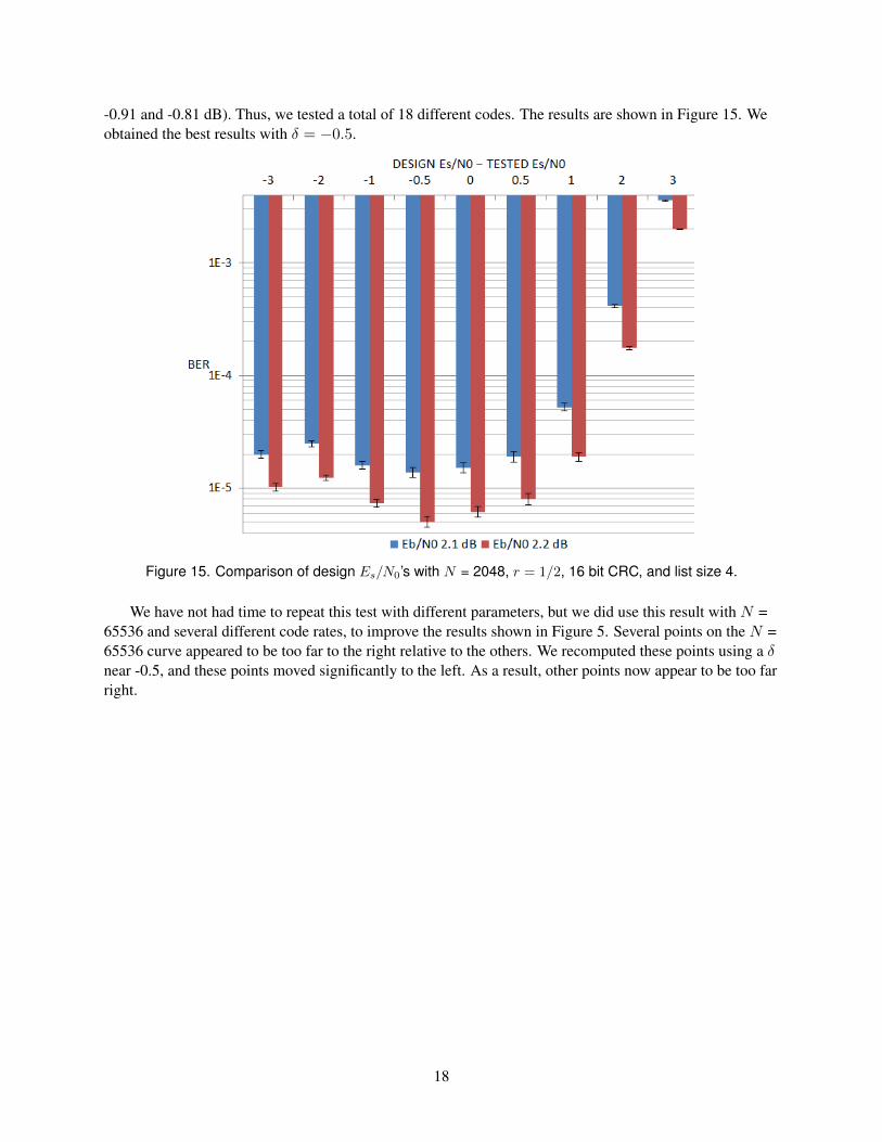
-0.91 and -0.81 dB). Thus, we tested a total of 18 different codes. The results are shown in Figure 15. Weobtained the best results with δ = −0.5.
Figure 15. Comparison of design Es/N0’s with N = 2048, r = 1/2, 16 bit CRC, and list size 4.
We have not had time to repeat this test with different parameters, but we did use this result with N =65536 and several different code rates, to improve the results shown in Figure 5. Several points on the N =65536 curve appeared to be too far to the right relative to the others. We recomputed these points using a δnear -0.5, and these points moved significantly to the left. As a result, other points now appear to be too farright.
18
6. IMPLEMENTATION DETAILS
Our decoder software is written in C++. It is based on the pseudocode in [5], which is designed to beused with a systematic polar encoder. Unlike most decoders described in the polar coding literature, thisdecoder does not use the logarithmic domain for probabilities. We used type long double for the prob-abilities.9
We made only four changes to the pseudocode from [5]. First, we corrected a mistake in algorithm15: lines 1 and 2 are misplaced; they belong after “continue”. The same correction recently appeared in alater version of the paper [13]. Second, we found that Algorithm 12 did not work as written. The indicesin pathIndexToArrayIndex are used both in arrayPointer_P, to point to float arrays, and inarrayPointer_C, to point to bit arrays. We found that when a float array is copied, the correspondingbit array must also be copied, and vice versa, so that the indexing remains consistent.
The third change is necessary because the pseudocode in [5] is for a non-CRC-aided decoder. TheCRC-checking part of the algorithm is described in the text, but no pseudocode is provided. We modifiedthe findMostProbablePath algorithm to implement CRC-checking.
Before calling findMostProbablePath, the decoder computes L candidate codewords x0 throughxL−1 and a probability pl for each one. The function findMostProbablePath keeps track of fourvariables:
• pPrime, the highest probability found so far
• lPrime, the index where pPrime was found
• pPrimeCrc, the highest probability found so far among codewords that pass CRC
• lPrimeCrc, the index where pPrimeCrc was found
lPrimeCrc is initialized to -1, which is invalid, and the other three are initialized to 0.
findMostProbablePath has a loop where the index l ranges from 0 to L − 1. If pl > pPrime,the function updates pPrime and lPrime. Then if pl > pPrimeCrc, the function checks to see if xl
passes CRC. If it passes, the function updates pPrimeCrc and lPrimeCrc. At the end of the loop, itcomputes the flag passedCrc = (lPrimeCrc > −1). If the flag is true, it returns lPrimeCrc as the mostprobable path index, otherwise it returns lPrime. Note that it is usually not necessary to check CRC forevery codeword in the list. passedCrc is also returned via pointer.
Checking the CRC is a three-step process. findMostProbablePath must first call a bit-reversalfunction to compute wl = ΠN xl, then copy some of the entries to form (wl)A, before it can compute theCRC.
The final change we made is that in [5], the decoder outputs the entire N -bit codeword x, but our de-coder outputs its estimate of the K-bit input to the polar encoder. This output is via pointer, and the returnvalue is passedCrc.
To test the decoder, we repeatedly generate Ki random bits, encode them, simulate transmission throughan AWGN channel, decode the channel output, and compare the random bits to the first Ki bits output bythe decoder. We did not count errors in the CRC bits.
9We used two different compilers. This type was 16 bytes in one compiler and 12 bytes in the other.
19

6.1 DECODING SPEED
Reference [13] shows that the list decoder requires O(LN logN) operations. With N = 65536, r =1/2, and L = 4, our decoder runs in 0.3 seconds on one core of an Intel R© Xeon R© X7560 processor. Thisspeed enables throughput of up to 100 kbps.
Our decoder is designed to be as simple as possible. Other CRC-aided list decoder designs have beenproposed to run much faster, both in software and hardware. Almost all such results concern block sizes512, 1024, or 2048. For example, [12] showed that a list decoder with N = 2048, r = 0.84, and L = 32could run in 433 ms, with throughput 33 Mbps. We have not seen any results that combined high speedwith the error-correction performance that we achieved with N = 65536. The closest is [14], which de-scribes a decoder with N = 32768, r = 0.9, and L = 32, but the speed of this decoder is not given. It achievesBER 10−5 at Eb/N0 4.2 dB, which is 0.3 dB worse than what we achieved at the same code rate with N =65536 and L = 4. We have not seen any other examples of CRC-aided list decoding with N > 2048 in theexisting literature.
If we assume that the decoder of [12] can be scaled up to N = 65536 with runtime proportional toO(N logN), it would run in 0.02 seconds, with throughput up to 23 Mbps, and would probably providea small coding gain over our decoder.
20
7. CONCLUSION
In any application for which the DVB-S2 FEC is considered, polar coding with CRC-aided list de-coding with N = 65536 should also be considered. With L = 4 in an AWGN channel it approximates theDVB-S2 results when compared at the same data rate, and can provide up to 15% higher throughput by us-ing code rates not provided in the DVB-S2 standard. The current runtime of 0.3 s may be fast enough forsome applications up to 100 kbps. Higher speed can be achieved using techniques in the existing literature.Further work is needed to accomplish the following:
• Incorporate these techniques into our software
• Test both polar coding and DVB-S2 coding with BER target 10−8
• Test both polar coding and DVB-S2 coding in more complex channel models such as Nakagami fad-ing
21

REFERENCES
1. Arıkan, E. 2009. “Channel Polarization: A Method for Constructing Capacity-Achieving Codes forSymmetric Binary-Input Memoryless Channels,” IEEE Transactions on Information Theory, vol. 55,no. 7, pp. 3051–3073.
2. Wasserman, D. 2014. “Polar Codes,” Technical Report 2054. Space and Naval Warfare Systems Cen-ter Pacific (SSC Pacific), San Diego, CA.
3. Tal, I. and Vardy, A. 2013. “How to Construct Polar Codes,” IEEE Transactions on Information The-ory, vol. 59, no. 10, pp. 6562–6582.
4. Arıkan, E. 2011. “Systematic Polar Coding,” IEEE Communications Letters, vol. 15, no. 8, pp. 860–862.
5. Tal, I. and Vardy, A. 2012. “List Decoding of Polar Codes,” arXiv preprint arXiv:1206.0050.
6. Kahraman, S. and Celebi, M. 2012. “Code Based Efficient Maximum-likelihood Decoding of ShortPolar Codes,” Proceedings of the 2012 IEEE International Symposium on Information Theory Pro-ceedings (ISIT) (pp. 1967–1971). July 1–6, Cambridge MA. IEEE.
7. Castagnoli, G., Ganz, J., and Graber, P. 1990. “Optimum Cycle Redundancy-check Codes With 16-bitRedundancy,” IEEE Transactions on Communications, vol. 38, no. 1, pp. 111–114.
8. Anonymous. 2015. “Cyclic Redundancy Check - Wikipedia, the free encyclopedia,” https://en.wikipedia.org/wiki/Cyclic_redundancy_check, accessed: 2015-07-10.
9. Koopman, P. and Chakravarty, T. 2004. “Cyclic Redundancy Code (CRC) Polynomial Selection forEmbedded Networks,” Proceedings of the International Conference on Dependable Systems and Net-works (pp. 145–154). June 28–July 1, Florence, Italy. IEEE.
10. Department of Defense. 2011. “Department of Defense Interface Standard MIL-STD-188-110C: Inter-operability and Performance Standards for Data Modems.”
11. Morello, A. and Mignone, V. 2006. “DVB-S2: The Second Generation Standard for Satellite Broad-band Services,” Proceedings of the IEEE, vol. 94, no. 1, pp. 210–227.
12. Sarkis, G., Giard, P., Vardy, A., Thibeault, C., and Gross, W. J. 2015. “Unrolled Polar Decoders, PartII: Fast List Decoders,” arXiv preprint arXiv:1505.01466.
13. Tal, I. and Vardy, A. 2015. “List Decoding of Polar Codes,” IEEE Transactions on Information The-ory, vol. 61, no. 5, pp. 2213–2226.
14. Sarkis, G., Giard, P., Vardy, A., Thibeault, C., and Gross, W. J. 2014. “Increasing the Speed of PolarList Decoders,” 2014 IEEE Workshop on Signal Processing Systems (SiPS) (pp. 1–6). October 2–22,Belfast, Ireland. IEEE.
22

5f. WORK UNIT NUMBER
REPORT DOCUMENTATION PAGE Form Approved
OMB No. 0704-01-0188 The public reporting burden for this collection of information is estimated to average 1 hour per response, including the time for reviewing instructions, searching existing data sources, gathering and maintaining the data needed, and completing and reviewing the collection of information. Send comments regarding this burden estimate or any other aspect of this collection of information, including suggestions for reducing the burden to Department of Defense, Washington Headquarters Services Directorate for Information Operations and Reports (0704-0188), 1215 Jefferson Davis Highway, Suite 1204, Arlington VA 22202-4302. Respondents should be aware that notwithstanding any other provision of law, no person shall be subject to any penalty for failing to comply with a collection of information if it does not display a currently valid OMB control number.
PLEASE DO NOT RETURN YOUR FORM TO THE ABOVE ADDRESS. 1. REPORT DATE (DD-MM-YYYY) 2. REPORT TYPE 3. DATES COVERED (From - To)
4. TITLE AND SUBTITLE 5a. CONTRACT NUMBER
5b. GRANT NUMBER
5c. PROGRAM ELEMENT NUMBER
5d. PROJECT NUMBER
5e. TASK NUMBER
6. AUTHORS
7. PERFORMING ORGANIZATION NAME(S) AND ADDRESS(ES) 8. PERFORMING ORGANIZATION REPORT NUMBER
10. SPONSOR/MONITOR’S ACRONYM(S)
11. SPONSOR/MONITOR’S REPORT NUMBER(S)
9. SPONSORING/MONITORING AGENCY NAME(S) AND ADDRESS(ES)
12. DISTRIBUTION/AVAILABILITY STATEMENT
13. SUPPLEMENTARY NOTES
14. ABSTRACT
15. SUBJECT TERMS
16. SECURITY CLASSIFICATION OF: a. REPORT b. ABSTRACT c. THIS PAGE
17. LIMITATION OF ABSTRACT
18. NUMBER OF PAGES
19a. NAME OF RESPONSIBLE PERSON
19B. TELEPHONE NUMBER (Include area code)
Standard Form 298 (Rev. 8/98) Prescribed by ANSI Std. Z39.18
August 2015 Final
Polar Coding with CRC-Aided List Decoding
David Wasserman
SSC Pacific, 53560 Hull Street, San Diego, CA 92152–5001
TR 2087
Naval Innovative Science and Engineering (NISE) Program (Applied Research) SSC Pacific, 53560 Hull Street, San Diego, CA 92152–5001
Approved for public release.
This is work of the United States Government and therefore is not copyrighted. This work may be copied and disseminated without restriction.
. This report describes some results of the project “More reliable wireless communications through polar codes,” funded in Fiscal Year 2015 by the Naval Innovative Science and Engineering (NISE) program at SSC Pacific. The purpose of the project is to determine if polar codes can outperform the forward error correction (FEC) currently used in Navy wireless communication systems. The project team has implemented an advanced decoding method called cyclic redundancy check (CRC)-aided list decoding. Our simulation results show that polar coding can produce results very similar to the FEC used in the Digital Video Broadcasting - Satellite - Second Generation (DVB-S2) standard, and can provide up to 15 percent higher throughput by using code rates not provided in the DVB-S2 standard.
In any application for which the DVB-S2 FEC is considered, polar coding with CRC-aided list decoding with N = 65536 should also be considered.
Mission Area: Communications polar codes polar encoder polar code construction cyclic redundancy check polar coding algorithms list decoding polar decoder Tal/Vardy Method forward error correction
David Wasserman
U U U U 31 (619) 553-3003

INITIAL DISTRIBUTION 84300 Library (2) 85300 Archive/Stock (1) 56270 D. Wasserman (1)
Defense Technical Information Center Fort Belvoir, VA 22060–6218 (1)

Approved for public release.
SSC Pacific San Diego, CA 92152-5001