poking the bear: drilling and
TRANSCRIPT

VOLUME 2
ISSUE 1
APRIL 2014
In this Issue Introduction……………………………………….….. 1
Poking the Bear: Drilling and Sampling for Embankment Dams….……...………………………. 2
Turning Rainfall to Runoff: Estimating Flood Inflows…………………………………… 10
What the Heck Should Be in My Spec? Part 2: Writing and Utilizing “Team-Effort” Specifications………………………………………………………………………………….. 16
1
A QUARTERLY PUBLICAT ION FOR WESTERN DAM ENGINEERS
Reclamation Hydrology Manual Unit Hydrograph Estimation Spreadsheet Link
Upcoming ASDSO Webinar Dam Safety Training:
Development of Operations and Maintenance Manuals For Dams, by Stephen Jamieson, P.E., May 13, 2014
Applications of PFMA in Dam Safety, by Doug Boyer, P.E., June 10, 2014
Upcoming ASDSO Classroom Technical Seminars
HEC-RAS, Manchester, NH, May 6-8, 2014.
Stability Analysis of Embankment Dams, Cincinnati, OH, June 3-5, 2014
ASDSO Training Website Link
In this issue of the Western Dam Engineering , we present articles on performing Technical Note
subsurface investigations for embankment dams, methodologies for developing inflow design hydrographs for small dam watersheds, and Part 2 of the technical project specification series focusing on “team effort” specifications. This quarterly technical note is meant as an educational resource for civil engineers who practice primarily in rural areas of the western United States. This publication focuses on technical articles specific to the design, inspection, safety, and construction of small dams. It provides general information. The reader is encouraged to use the references cited and engage other technical experts as appropriate.
The Western Dam Engineering Technical Note is sponsored by the following agencies:
Colorado Division of Water Resources Montana Department of Natural
Resources Wyoming State Engineer’s Office
This news update was compiled, written, and edited by URS Corporation in Denver, Colorado.
Funding for the Technical Note has been provided by the FEMA National Dam Safety Act Assistance to States grant program.
Article Contributors: URS Corporation: Dale Baures, PE, PG; Dennis Miller, PE; Chad Vensel; Jennifer Williams, PE; Jason Boomer, PE; John France, PE Editorial Review Board: Michele Lemieux, PE, Montana Dam Safety
Program Supervisor; Bill McCormick, PE, PG, Colorado Chief Dam Safety Branch; Mike Hand, PE, Wyoming Dam Safety Program; Mark Ogden, PE, Association of State Dam Safety Officials; Matthew Lindon, PE, Loughlin Water Associates; and Steve Becker, PE, Natural Resources Conservation Service
GOOD TO KNOW
The material in this publication has been prepared in accordance with generally recognized engineering principles and practices, and is for general information only. The information presented should not be used without first securing competent advice from qualified professionals with respect to its suitability for any general or specific application. No reference made in this publication constitutes an endorsement or warranty thereof by URS Corporation or sponsors of this newsletter. Anyone using the information presented in this newsletter assumes all liability arising from such use.

Western Dam Engineering
Technical Note
2
Poking the Bear: Drilling and Sampling for Embankment Dams Subsurface investigations that include drilling and sampling are often used to obtain geotechnical information about embankment dams and their foundations. However, performing these intrusive investigations does not come without risk and unique considerations. Drilling could connect existing seepage paths or weak zones within the embankment, or create such by fracturing or disturbing the material. As such, drilling with fluids within embankment dams is particularly adverse. Drilling a hole in or near a dam to collect in situ information and samples should therefore only be performed if warranted, under supervision of a driller and field engineer with experience drilling in embankment dams, and executed based on a well thought-out plan. The plan should include the purpose and goals of the investigation and address concerns associated with drilling through an embankment dam. Intrusive drilling and sampling are usually conducted after other non-intrusive investigations have been completed, including review of existing information, mapping of rock and soil exposures, and perhaps geophysical surveys. Intrusive methods are prescribed after it has been determined that analyses requiring site-specific geotechnical information are warranted.
In the last issue of the Western Dam Engineering Technical Note, we discussed ways to evaluate stability and determine whether more in-depth analyses are warranted. In this edition, we include some methods of drilling and sampling embankment dams typically used to support those studies. The purpose of this technical note is to discuss general guidelines for evaluating and selecting the drilling and sampling methods that are currently available in most parts of the United States. Additional, less common, methods exist that have not been included. The discussion begins with general sampling and drilling methods for embankment dams, followed by guidelines for drilling and sampling in the core of the embankment, the embankment shell, and the foundation.
Importance of Investigation Plans
A geotechnical investigation for an embankment dam that involves drilling and sampling in test holes should begin with a carefully thought-out plan that addresses the objectives and purpose of the work and lays out detailed specifics of the drilling and sampling approach. Most projects will have existing information available
about the dam and foundation that can be used to provide an estimate of the type and location of materials that might be encountered. This information will be helpful to determine appropriate drilling methods, the estimated depth, inclination, and diameter of test holes, and the types of samples that should be obtained. The contents of this article should be carefully considered when selecting the hole location and drilling method. In particular the reasons to not drill with fluid through the embankment (and with it in the foundation) should be heeded.
Drilling and sampling usually forms only a part of the investigation plan. The investigation plan should also consider site access conditions, utilities, health and safety requirements, test hole completion and abandonment, installation of instrumentation, in situ testing, sample handling, storage of samples, transportation of samples, and laboratory testing. The investigation plan should also consider the target drilling and sampling depths and expected phreatic surface.
Perhaps the most important part of the investigation plan is to be flexible and have contingencies for unknown conditions often encountered in the subsurface. Flexibility can be achieved by having several different drilling and sampling methods available with the drill rig selected for the investigation. An example contingency for drilling would be to have extra drill rods on the rig, should the test hole(s) need to go deeper or have a string of casing available for caving hole conditions. An example contingency for sampling would be to have a variety of samplers on the rig to select the one most appropriate for the soils encountered.
Drilling and sampling in an embankment dam has associated risk of damaging the embankment; therefore, the investigation plan should include procedures to arrest damage if it is observed or suspected. Drains, embankment slopes, and piezometers can be monitored to observe changes during the drilling and sampling. If the embankment is considered particularly sensitive to potential changes (i.e., the dam has shown signs of instability, seepage, or piping) materials such as gravel, sand, bentonite, etc. can be stockpiled near the test hole with equipment for transport to the test hole, should damage become apparent. Signs of embankment disturbance may include increased seepage downstream of the test hole, seepage turning turbid, or sinkholes/depressions forming on the surface of the embankment. At a minimum the accessibility of the nearest source of emergency materials should be

Western Dam Engineering
Technical Note
3
identified. The investigation plan might also include phone numbers to communicate events, written procedures to help promptly deal with unusual conditions or damage, and guidelines for the work associated with the drilling and sampling.
Typical Sampling Methods Appropriate sampling methods vary based on the target strata being investigated. This is a general summary of typical methods for obtaining samples to characterize embankment dam materials. Refer to the referenced ASTM standard for detailed information on each sampling type and method.
Photo 1. Example Samplers (Photo Courtesy of CME)
Split spoon sampling using Standard Penetration Test procedures (SPT) (ASTM D1586): A split spoon sample is a driven-sample generally obtained using the SPT method. This provides both an in situ test of the relative consistency (density/stiffness) of the material and obtains a disturbed sample. Split spoon samples can be performed in most soil types and weak rock, but are not appropriate for strong rock. If the material is non-cohesive (sandy), then various catchers may be used at the sampler tip to help retain the sample; however, these may affect SPT results is low strength material. The resulting sample is appropriate for index testing (gradation, plasticity, moisture content, etc.). Samples should be removed from the sampler and placed in sealed plastic baggies to retain moisture. (Laboratory testing of samples will be discussed in a subsequent issue.)
Thick-walled split tube sampling (i.e., modified California sampler, ASTM D3550): is a driven-sampling method using a ring-lined barrel that provides a slightly less disturbed sample of soils and weak rock, but is not appropriate for strong rock. This sampling method is also often used following SPT procedures. It is preferred over the split spoon when a less disturbed sample is desired and the material has sufficient cohesion to be retained in the sampler. The ring sample should be carefully sealed with wax or taped plastic caps. The ring samples can best be used for index property characterization (gradation, plasticity, moisture content, etc.). Use caution performing tests on these samples, when they are intended to represent in-place properties such as density and strength, as some disturbance of the soil likely occurred.
Thin-walled sampling (i.e., Shelby tube, ASTM D1587): Shelby tube sampling is a push-sample method that provides a relatively undisturbed sample of fine-grained, cohesive material. It may be difficult for sampling non-cohesive or granular material such as sands or gravels, as they are difficult to retain in the tube, although special procedures have been developed for thin walled sampling of sands using fixed piston samples, which provide for development of vacuum in the soil pores during sample extraction. Tube sampling of sands requires great skill and care and special precautions must be taken to limit disturbance of these samples during transportation. Quality Shelby tube samples are appropriate for testing index properties as well as in-place characteristics such as density, consolidation, and strength properties, as this method generally results in the least disturbance of soil sampling when performed properly. Samples should be retained within the tube to allow the laboratory to carefully extrude the sample. Sample disturbance and change in sample condition is likely if the sample is extruded in the field. The tube should be carefully sealed with wax or o-ring packers. Care should be taken to avoid sample disturbance during transportation to the laboratory, especially for soft soil samples.
Core sample: A “core” sample refers to a relatively continuous sample recovery of the drilled material. Core samples are obtained through the drilling process itself. Sample cores can be relatively undisturbed or disturbed based on the drilling method used. Core samples can be obtained using diamond coring, sonic drilling, and even auger drilling when a plastic-lined auger string is utilized. Undisturbed core samples are appropriate for testing index properties as well as in-place properties such as
Split Spoon
Shelby Tubes
California Tube Sampler

Western Dam Engineering
Technical Note
4
density, consolidation (in the case of soil cores), rock quality (in the case of rock cores), and strength properties.
Typical Drilling Methods Six general methods of drilling are presented herein that are typically considered in the investigation of embankment dams. The methods include auger drilling, core drilling, mud rotary drilling, Odex drilling, sonic drilling, and Becker drilling. A number of other methods exist; however, these six have been found to be most commonly used in the United States. Refer to the referenced ASTM standard for detailed information for each drilling method.
Auger Drilling Auger drilling is one of the most commonly used methods of drilling, and for embankment dams should be the preferred method, if possible due to its low risk of embankment damage, cost, versatility and availability. Many drill rigs can be set up to use solid flight auger (ASTM D1452) and hollow stem auger (ASTM D6151) strings. Auger drilling requires a high torque and low revolution speed rig, and with care depths of 200 to 300 feet can be drilled. Auger drilling does not require the use of drilling fluid; however, in some materials water may be poured into the test hole to aid in removing cuttings. Auger drilling is appropriate for fine-grained soils, granular soils, and weak rock, but may have difficulty advancing in very dense and/or very coarse-grained granular material due to friction. It is not appropriate for strong rock. Auger drilling allows for split spoon (SPT), Shelby tube, and thick-walled tube sampling.
Photo 2. Auger Drill Rig
A track mounted drill rig using a 6-inch hollow stem auger (HSA) is shown in Photo 2. The string of 6-inch HSA has an inside diameter of 3 ¼ inches. This configuration allows use of the auger string as casing. Sampling and deepening the hole below the lead auger can be accomplished by switching to mud rotary or core drill strings. Note the added precautions necessary, particularly access and safety, when drilling on the steep incline of an embankment slope.
Auger Drilling Considerations
Pros Cons
Can drill through loose/soft to dense/hard material and possibly weak rock
Not suitable for strong rock or some larger diameter granular material (i.e., cobbles and boulders)
HSA casing provides some embankment protection
Auger string may deviate more easily than other drilling methods
Drilling fluid not required
Generally less expensive; available in most parts of the US
HSA casing allows easy access for most sampling techniques including core barrel [although test hole not filled with mud per ASTM standard of SPTs (ASTM D1586)]
Core Drilling Core drilling (ASTM D2113), also referred to as diamond core drilling, can be used to obtain continuous sample cores of soil and rock, although this method is most commonly associated with drilling and sampling in rock. Drilling fluid, if required, can be air, water, or mud. SPT samples can be obtained from the inside of the drill string when the core barrel has been removed; however, this presents a risk of damaging the diamond bit. Because drilling fluid (water, mud, or air) is used, this method should not be used within embankments. If used within a rock foundation below an embankment, the hole should be cased within the embankment zone with the casing seated in the underlying bedrock, and preferably drilled through an outer shell zone.
In Photo 3 below, a track mounted core rig is shown advancing a test hole at an angle of 25° from vertical. The drill rod on the pipe rack is “HQ” size (4-inch diameter hole) from a wireline core string, which allows retrieval of the core samples as the test hole is deepened without having to trip out the drill string.

Western Dam Engineering
Technical Note
5
Photo 3. Core Drill Rig
Core Drilling Considerations
Pros Cons
Can drill through almost all soils and rock; however, typically used in rock
Drilling fluid such as air, water, or mud is likely required
Casing can be used to provide embankment protection
Generally more expensive; but widely available in the US
Yields a continuous core Core sample may be disturbed and recovery may be low in some materials
Performing SPT tests are time consuming
Mud Rotary Mud rotary (aka rotary wash) drilling (ASTM D5783) is probably the most common soil and rock drilling method used in the United States for a wide range of purposes; however, it is not recommended for drilling in and around dams. Air can be used as a drilling fluid (ASTM D 5782); however, some type of drilling mud is typically used. Mud rotary is appropriate for drilling in almost all soil and rock materials. It is different from diamond core drilling in that it uses a rock or tricone-type bit at the tip of the drill string and therefore only produces cuttings during drilling rather than a continuous core.
Mud is generally used to stabilize the hole rather than casing. As the test hole is drilled, mud inside the hole is maintained at a level near the collar of the hole to help keep the hole open and form a mud cake on the walls of the test hole. Drilling with a casing advancer (ASTM D 5872) is a method related to mud rotary drilling and uses casing as the drill string, with a wireline tri-cone bit in the lead casing. A casing advancer drill string is often used for materials such as flowing sands or loose gravels that may
not allow the test hole to remain open with only the drill fluid. In some parts of the country (the northeast for example), this method is sometimes used with water instead of mud as the fluid – commonly called cased wash borings. Similar to that described for core drilling, mud rotary should not be performed through embankment dams due to the use of drilling fluid and the potential to hydraulically fracture any encountered weaknesses, even if a casing advancer is used. Similar to auger drilling, mud rotary drilling itself does not produce a sample, only cuttings. However, most sampling methods can be used in mud rotary-drilled holes by removing the drill string from the hole and lowering the sampler. This includes the potential use of diamond core strings to obtain continuous core samples.
In Photo 4, a truck mounted CME-75 drill rig is equipped with a string of “N” rod and a tri-cone bit to drill into alluvium. A string of “A” rod was used to conduct in situ testing and obtain SPT samples.
Mud Rotary Drilling Considerations
Pros Cons
Can drill through almost all soil and rock and a wide range of drilling conditions
Drilling fluid such as air, water, or mud is required.
Generally least expensive and most widely available method in all parts of US
Should not be performed through embankments due to fluid pressure, even if cased
Easy to switch out drill string to obtain samples, although the drill method itself only produces cuttings
Photo 4. Mud Rotary Drill Rig

Western Dam Engineering
Technical Note
6
Odex Drilling Odex drilling (also known as TUBEX) is a percussive drilling method that uses an air powered down-the-hole hammer to advance a casing string. Odex casing can be driven through almost all soil and rockfill materials and weak rock in the foundation. SPT and core samples can be obtained through the inside of the casing by changing the drill string and other methods of drilling can be used to deepen the test hole, if required. Drill fluid consists of air and a large air compressor is required. During drilling cuttings from inside the casing are carried to the surface using air. Odex drilling is generally not advisable within the embankment portion of the dam due to the potential damage that can be induced by the percussive action of the hammer and the high pressure air used for cuttings removal.
Odex Drilling Considerations
Pros Cons
Can drill through loose/soft to very dense/hard material, and rock fill
Not suitable for strong rock
Casing provides embankment protection
Generally more expensive and less widely available
Samples can be obtained after the hammer is pulled from the casing
Performing SPTs are more difficult/costly than with HSA
Air required as a drilling fluid
Photo 5. Odex Drill Rig
Sonic Drilling Sonic drilling (ASTM D6914) uses an oscillating hammer in the drill head to vibrate and advance the drill casing. This drilling method provides almost continuous sample recovery of drilled material in the form of a continuous,
albeit disturbed, core. Sonic drilling can be used to efficiently advance through almost all soil and weak rock; however, slow drilling and refusal may be encountered in strong rock or large boulders. Flowing sands and gravels may be problematic and fall out when pulling the core barrel. Drill fluid is not required for sonic drilling; however, some water may be poured into the casing to reduce friction and to keep the sample cool. Samples other than the sonic core (i.e. SPT, Shelby tube, etc.) can be obtained through the casing after the wireline core barrel has been retrieved; however, sampling is time consuming.
The test hole can be deepened into rock upon refusal using mud rotary or core drilling methods. Sonic drilling is generally preferred for drilling through coarse or dense embankment materials over Odex due to the limited potential disturbance. However, it is generally one of the most expensive drilling methods.
Photo 6. Sonic Drill Rig
Sonic Drilling Considerations
Pros Cons
Can quickly drill through loose/soft to very dense/hard material
Slow and inefficient for strong rock with a potential for refusal
Casing provides embankment protection
Generally more expensive and less widely available
Yields a continuous core Core sample is disturbed
Drilling fluid not required Performing SPT tests is more difficult/costly
Limits embankment disturbance compared to percussive methods or mud rotary methods
May result in disturbance of loose in-place material, and therefore care should be taken when performing SPTs

Western Dam Engineering
Technical Note
7
Becker Drilling Becker drilling (ASTM D 5781) uses an AP-1000 diesel hammer to drive double walled casing. Becker casing can be driven through almost all materials within the embankment dam and weak rock in the foundation. SPT and core samples can be obtained through the inside of the casing and other methods of drilling can be used to deepen the test hole, if required. Drill fluid is not required for this drilling method; however, some water may be poured into the casing to reduce friction. During drilling cuttings from inside the casing are carried to the surface using reverse circulation air and separated using a cyclone.
In Photo 7 below, a truck mounted AP-1000 Becker rig and required pipe truck is shown set up on a test hole. The Becker casing on the pipe truck is 9-inch diameter, with an inside diameter of about 4 inches (with a crowd in bit). Note the drill pad size required for the Becker rig and pipe truck, which is about 120 feet long and 20 feet wide. The pipe truck is typically set up behind the Becker rig to allow safe handling of the heavy casing.
Becker Hammer Drilling Considerations
Pros Cons
Can drill through loose/soft to very dense/hard material, and rock fill
May not suitable for strong rock
Casing provides embankment protection
Generally more expensive and less widely available
Yields continuous cutting samples Performing SPT are more difficult/costly than with HSA
Drilling fluid not required
Becker blow count can be correlated to SPT blow count
Photo 7. Becker Drill Rig
The drilling and sampling descriptions above provide limited information about the equipment. Refer to the ASTM standards for detailed descriptions and considerations to use when selecting drilling and sampling methods. ASTM D 6286 (Standard Guide for Selection of Drilling Methods for Environmental Site Characterization) may be useful for comparing drilling methods and selecting a preferred method for the investigations. Often the best source of information when selecting drilling and sampling methods is drilling company employees familiar with the equipment they use. If possible discuss your proposed drilling and sampling plan with the driller you plan to work with before heading into the field. If multiple drilling and sampling methods are to be used, it will be important to check the feasibility of the investigation plan with the driller.
Drilling and Sampling the Core Zone The core zone of the dam refers to the generally fine-grained, low permeable zone of the embankment that is the primary seepage barrier. Drilling and sampling in the core zone of an embankment dam risks damage to the core. If possible, drilling and sampling in the core should be avoided. Alternatives should be considered to obtain the same or similar information by doing investigations at locations outside the core. For example, drilling through the shell or toe area is preferred if the primary objective is obtaining information on the foundation. If no alternatives are available, the preferred method of drilling in the core zone should be auger drilling. Auger drilling can be done without the use of drilling fluid (air, water, or mud) and therefore limits the risk of hydraulic fracturing of materials comprising the embankment core that could lead to internal erosion and piping damage. If drilling with water or mud must be conducted, limit the effective head to 0.5 psi per foot of vertical depth to reduce risk of hydraulic fracturing. Never drill in the cut-off trench, adjacent to outlet works or conduits, in or near known areas of seepage, and at locations above abrupt changes in the shape of the foundation. These may be areas of low stress that are more susceptible to damage due to drilling-induced disturbance or may be areas in which a drill hole could connect concentrated seepage paths.
Drilling and Sampling the Shell Zone(s) Drilling and sampling in the shell(s) of an embankment dam may require the same considerations as drilling and sampling in the core, especially if the shell was constructed from fine-grained material. Shells

Western Dam Engineering
Technical Note
8
constructed of coarse-grained earth fill or rock fill can be drilled and sampled using any of the appropriate methods described above. Risk of contaminating and plugging filters and drains should be considered; therefore, if possible use an auger drilling method because drilling mud is not required. If auger drilling is impossible due to flowing ground conditions, consider using a casing advancer method and keep the casing full of water or drilling mud at all times. If gravel, cobbles, and boulders are encountered, consider using the sonic drilling method or the core drilling method. Embankment shells constructed with rock fill may contain large boulders in which refusal may be encountered when using auger or even sonic drilling methods in some cases. A flexible investigation plan with contingencies for potential problems should be considered. For example, in the case of refusal, a pilot hole can be made with a core drill string to investigate whether refusal is due to a discrete boulder, in which case the auger string or sonic string could then ream the pilot hole and advance the test hole through the boulder.
Drilling and Sampling the Foundation Subsurface investigations of the foundation material can be performed either through the embankment or outside the dam footprint. Either location has precautionary considerations. We have discussed the care needed to drill through the embankment and that is also reiterated in the paragraph below. Investigations within the foundation outside the dam footprint also need to consider the risk of blowing out foundation material. Drilling or excavating test pits near the toe, especially when the reservoir is near full pool, could provide an easy exit for foundation pore pressures, resulting in the potential for heave or blowout of the foundation. Larger excavations such as test pits, especially those below the water table, could exacerbate this risk. Offsetting borings a distance away from the toe, lowering the reservoir if possible, and drilling borings using fluid or mud help reduce the risk. This should be evaluated based on the specific foundation conditions expected at the site.
In cases in which the test hole will extend through the embankment (hopefully the shell) and into the underlying foundation, the materials to be drilled and sampled will likely vary and may require different drilling and sampling methods with depth. The investigation plan will need to address how to safely drill through the embankment and continue into the foundation. An example might be to use the hollow-stem auger drilling method to advance the test hole to the top of a rock foundation, then use the
auger as casing and seat the lead auger into the foundation, then advance the test hole into the foundation using the core drilling method. The investigation plan, especially the drilling and sampling approach, should be discussed with the driller prior to start of the work so that potential equipment problems can be identified. In many cases, the driller will offer good ideas for conducting the drilling and sampling if they are well-informed of the objectives of the investigation.
SPT Sampling for Liquefaction SPT sampling for liquefaction evaluation is very specialized procedure. Special care is required when sampling very loose sands. By standard procedure, water or mud is required in the hole when performing SPT sampling. This limits the potential of causing flowing or heaving in loose sands, which would disturb the in situ test. As mentioned earlier, fluid is not recommended in borings within embankment dams; however, compacted embankment materials are not common targets of liquefaction evaluation. Certain drilling methods may also disturb the area, especially in loose soils. Precautions should be implemented to limit drilling disturbance in the target zone for liquefaction evaluation. This may include switching drilling methods to auger methods in the target zone, which generally results in the least disturbance, and extracting drill strings at a slow rate to avoid a vacuum effect. The procedure may also require corrections for gravel content, which dictates the method to be used for blow count. The Reclamation guidance manual on SPT sampling (Reclamation 1999) should be referenced for more detail.
Test Hole Backfilling If the test hole is not being completed as a piezometer, then it should be backfilled in such a manner to limit potential for a weak zone or seepage paths in or around the hole. Backfilling using cement/bentonite grout placed using tremie (bottom-up) methods should be required in or near the dam. Bentonite chips (also known as “hole plug") can also be used. Bentonite chips expand upon saturation, so the hole should be wetted as chips are placed. Backfilling test holes using cuttings should never be performed in holes within the embankment, foundation, abutment, or toe area of dam, as this could cause the surrounding soil to creep, deform, or result in increased seepage.
Conclusions Drilling and sampling for embankment dams should be initiated with the preparation of a geotechnical

Western Dam Engineering
Technical Note
9
investigation plan. The preferred method of drilling and sampling on and around dams is with the hollow stem auger drilling method, as this method best protects the embankment. Sonic drilling should be the next preferred method if the auger method will not work, such as in rockfill. If possible, avoid drilling in the core zone of the embankment. Never drill in the cut-off trench, near conduits in the embankment, or in areas that may be susceptible to damage. Prior to and during drilling, conditions at the dam should be monitored by reading piezometers and seepage weirs, and visually observing for signs that drilling and sampling might be causing damage to the embankment or foundation. Consider including procedures for dealing with damage to the embankment in the geotechnical investigation plan. Always review your drilling and sampling plan with the appropriate dam safety regulator as part of the investigation plan development process.
References [1] ASTM D1452-09 Standard Practice for Soil Exploration and Sampling by
Auger Borings.
[2] ASTM D1586-11 Standard Test Method for Standard Penetration Test (SPT) and Split-Barrel Sampling of Soils.
[3] ASTM D1587-08 (2012) Standard Practice for Thin Walled Tube Sampling of Soils for Geotechnical Purposes.
[4] ASTM D2113-08 Standard Practice for Rock Core Drilling and Sampling of Rock for Site Investigation.
[5] ASTM D3350 01(2007) Standard Practice of Thick Wall, Ring-Lined, Split Barrel, Drive Sampling of Soils.
[6] ASTM D5781/D5781M-13 Standard Guide for Use of Dual-Wall Reverse-Circulation Drilling for Geoenvironmental Exploration and the Installation of Subsurface Water-Quality Monitoring Devices.
[7] ASTM D5782-95 (Reapproved 2000) Standard Guide for Use of Direct Air-Rotary Drilling for Geoenvironmental Exploration and the Installation of Subsurface Water-Quality Monitoring Devices.
[8] ASTM D5783-95 (Reapproved 2000) Standard Guide for Use of Direct Rotary Drilling with Water-Based Drilling Fluid for Geoenvironmental Exploration and the Installation of Subsurface Water-Quality Monitoring Devices.
[9] ASTM D5872-95 (Reapproved 2000) Standard Guide for Use of Casing Advancement Drilling Methods for Geoenvironmental Exploration and the Installation of Subsurface Water-Quality Monitoring Devices.
[10] ASTM D6151-08 Standard Practice for Using Hollow-Stem Augers for Geotechnical Exploration and Soil Sampling.
[11] ASTM D6286-12 Standard Guide for Selection of Drilling Methods for Environmental Site Characterization.
[12] ASTM D6914-04 Standard Practice for Sonic Drilling for Site Characterization and the Installation of Subsurface Monitoring Devices.
[13] U.S. Dept. of Interior, Bureau of Reclamation (Reclamation), 1999. Standard Penetration Test Driller’s/Operator’s Guide. DSO-98-17. Earth Sciences and Research Laboratory, Dam Safety Office.

Western Dam Engineering
Technical Note
10
Turning Rainfall to Runoff: Estimating Flood Inflows
One of the most critical components of a safe dam is the adequacy of a spillway to safely pass the inflow design flood. Inflow design flood requirements are typically based on the potential hazard a dam poses to downstream floodplains and communities (hazard class) and are usually stipulated by the regulating agency for the structure. The inflow design flood itself is a function of rainfall, including distributions and patterns for a particular storm event frequency, and pertinent watershed characteristics. These pertinent watershed characteristics influence the rate and volume at which rainfall is “lost” and the conversion of the excess rainfall to a runoff hydrograph.
The purpose of this article is to present an overview of the processes and methodologies available for estimating the effects of watershed characteristics on runoff and the transformation of excess precipitation to an inflow design flood hydrograph. This overview is generally based on small dam watersheds throughout the western U.S. with a focus on Colorado, Montana, Utah and Wyoming. Pertinent reference documents are also presented.
Rainfall Event Characteristics
Before watershed runoff can be estimated, rainfall event characteristics must be defined. In the last issue of the Western Dam Engineering Technical Note we discussed the guidelines and estimation of precipitation depths and intensity-duration-frequency (IDF) relationships. In addition, each rainfall event must also be characterized by:
Spatial patterns – The physical path of the rainfall event over the watershed.
Temporal distribution – The variation of rainfall with time (i.e. intensity) during the rainfall event.
Aerial reductions – A reduction in rainfall depth as a result of distributing point rainfall depth, as estimated for frequency and Probable Maximum Precipitation (PMP) events, over the watershed. Further reductions may also apply for watersheds located at sufficiently high elevations.
Rainfall weighting – The process of developing incremental rainfall depths, based on equivalent blocks of time (i.e. hyetograph), for the duration of the rainfall event and arranging them such that the
peak rainfall depth occurs at a specific percentage of the event duration.
These rainfall event characteristics can significantly influence the rate and volume of runoff; however, are outside the scope of this article. The reader is encouraged to further investigate these aspects of rainfall characterization. The primary focus of this article is runoff, so we will begin with basin losses.
Basin Loss Parameters and Excess Rainfall
Excess rainfall, or runoff, is the portion of rainfall that is not “lost” during the rainfall event. Rainfall losses are not actually “lost,” but are defined as such because they represent the portion of rainfall that does not contribute to runoff and to the subsequent watershed outflow hydrograph (i.e. reservoir inflow hydrograph). The “losses” are instead recycled back to the system through various means. A visual representation of this rainfall-runoff process is presented in Figure 1.
Rainfall losses are generally defined by:
Interception - The portion of rainfall that wets and adheres to above ground vegetation and is eventually evaporated.
Depression storage - The portion of rainfall that collects and is retained in surface depressions, which are either impermeable or characterized by infiltration rates less than that of the event rainfall intensity (i.e. excess rainfall is produced, but does not contribute to the total runoff). The retained rainfall is eventually either evaporated or infiltrated.
Evaporation – The portion of rainfall that is directly evaporated based on atmospheric conditions during a given rainfall event.
Infiltration – The portion of rainfall that moves downward through surface soils and eventually recharges aquifers and supports baseflow of the stream.

Western Dam Engineering
Technical Note
11
Figure 1: The rainfall-runoff process with losses.
The rate and volume of rainfall losses, and subsequently runoff, are influenced by a number of factors including:
Rate of rainfall (i.e. intensity) as well as rainfall distribution and patterns
Watershed pervious and impervious areas
Soil infiltration rates
Watershed properties like roughness, vegetative cover, soil properties and slope
Numerous rainfall loss estimation methodologies are available; however, with an interest in brevity and specific application to the western U.S., three of these methodologies will be presented in the following sections.
Green and Ampt Infiltration Loss Methodology
The Green and Ampt methodology is an approach based on the soil-water system where the inherent soil properties can be physically measured. It is particularly applicable for frequency event storms more frequent than and including the 100-year storm event, but can also be applied to less frequent storm events.
In general, the Green and Ampt methodology is based on the following factors:
Surface Retention (Initial) Loss o Depression storage o Interception by vegetation
Infiltration Loss o Hydraulic conductivity at natural saturation; o Wetting front capillary suction; and o Volumetric soil moisture deficit at the start of
rainfall
Imperviousness of the watershed
A simplified definition sketch of the Green and Ampt methodology is presented in Figure 2 and is representative of the aforementioned factors.
The Green and Ampt methodology is fairly comprehensive and accurate; however, as a consequence, the process of estimating the aforementioned parameters has been historically more cumbersome than other methodologies. However, modern GIS techniques can be applied to simplify the effort required to estimate pertinent parameters. See references [2] and [6] regarding application and use of
Western Dam Engineering
Technical Note
12
the Green and Ampt methodology. Reference [6] also provides a spreadsheet solution to reduce the time required for parameter development.
Figure 2: Green and Ampt methodology rainfall loss model (Source: DWR, 2008).
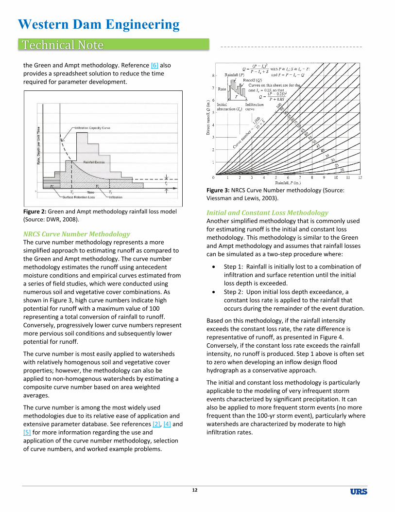
NRCS Curve Number Methodology The curve number methodology represents a more simplified approach to estimating runoff as compared to the Green and Ampt methodology. The curve number methodology estimates the runoff using antecedent moisture conditions and empirical curves estimated from a series of field studies, which were conducted using numerous soil and vegetative cover combinations. As shown in Figure 3, high curve numbers indicate high potential for runoff with a maximum value of 100 representing a total conversion of rainfall to runoff. Conversely, progressively lower curve numbers represent more pervious soil conditions and subsequently lower potential for runoff.
The curve number is most easily applied to watersheds with relatively homogenous soil and vegetative cover properties; however, the methodology can also be applied to non-homogenous watersheds by estimating a composite curve number based on area weighted averages.
The curve number is among the most widely used methodologies due to its relative ease of application and extensive parameter database. See references [2], [4] and [5] for more information regarding the use and application of the curve number methodology, selection of curve numbers, and worked example problems.
Figure 3: NRCS Curve Number methodology (Source: Viessman and Lewis, 2003).
Initial and Constant Loss Methodology Another simplified methodology that is commonly used for estimating runoff is the initial and constant loss methodology. This methodology is similar to the Green and Ampt methodology and assumes that rainfall losses can be simulated as a two-step procedure where:
Step 1: Rainfall is initially lost to a combination of infiltration and surface retention until the initial loss depth is exceeded.
Step 2: Upon initial loss depth exceedance, a constant loss rate is applied to the rainfall that occurs during the remainder of the event duration.
Based on this methodology, if the rainfall intensity exceeds the constant loss rate, the rate difference is representative of runoff, as presented in Figure 4. Conversely, if the constant loss rate exceeds the rainfall intensity, no runoff is produced. Step 1 above is often set to zero when developing an inflow design flood hydrograph as a conservative approach.
The initial and constant loss methodology is particularly applicable to the modeling of very infrequent storm events characterized by significant precipitation. It can also be applied to more frequent storm events (no more frequent than the 100-yr storm event), particularly where watersheds are characterized by moderate to high infiltration rates.

Western Dam Engineering
Technical Note
13
Figure 4: Initial and Constant Loss methodology rainfall loss model (Source: DWR, 2008).
Additional Watershed and Methodology Considerations
Watershed Characteristics
Wild fires can significantly alter the pertinent watershed characteristics that affect runoff. For this reason, burned areas within study watersheds should be assessed with particular scrutiny.
For some watershed studies, it could be prudent to consider not only present watershed characteristics, but also potential future watershed characteristics. Potential development and “urbanization” of watersheds can significantly increase runoff.
Green and Ampt Methodology
Use of the Green and Ampt methodology is generally preferable for projects that warrant precision.
Although perhaps more time consuming than other methodologies, it can be applied for any event frequency with a relatively high level of accuracy.
Curve Number Methodology
Application of the curve number methodology is generally not recommended for soil and land cover combinations that yield curve numbers less than about 40.
The curve number methodology is used successfully and extensively by the engineering community due to its ease of use and sufficient accuracy. Readers are cautioned, however, because the curve number has been shown to be less accurate than some physically-based
infiltration methodologies due to its empirical nature. This aspect is presented not to discourage its use, but rather to highlight its applicability to a particular project. If a high level of accuracy is required for a particular project, use of the curve number methodology can be inadequate.
It is recommended, particularly for projects where a high level of accuracy is required, to independently verify curve number methodology results with another runoff estimation methodology.
Transforming Excess Rainfall to Flow Hydrographs Runoff rates are converted to flow hydrographs using a translation methodology. Numerous translation methodologies exist; however, the unit hydrograph methodology is used extensively and is generally the most preferred.
A unit hydrograph is defined as the time distribution of one inch of runoff from a storm event of a specified duration for a particular watershed, as presented in Figure 5. Unit hydrographs are reflective of the physiography, topography, land-use, and other unique characteristics of the individual watershed and assume that rainfall is uniformly distributed across the watershed. As such, different unit hydrographs are developed for the same watershed for different durations of rainfall excess.
Ideally, a unit hydrograph would be developed based on gage and calibrated watershed data; however, engineers are frequently confronted with project watersheds that lack sufficient data to develop a unit hydrograph. As such, synthetic unit hydrographs are developed based on available watershed data at other locations that have hydrologic characteristics similar to those of the project watershed.
Numerous synthetic unit hydrograph methodologies exist; however, for the purposes of application to the western U.S., the following methodologies are most pertinent:
U.S. Department of the Interior, Bureau of Reclamation (Reclamation) synthetic unit hydrograph as presented in the Flood Hydrology Manual (Cudworth, 1989)
Clark synthetic unit hydrograph
U.S. Geological Survey (USGS) synthetic unit hydrograph specific to Montana as presented in

Western Dam Engineering
Technical Note
14
Procedures for Estimating Unit Hydrographs for Large Floods at Ungaged Sites in Montana (Holnbeck and Parrett, 1996)
Figure 5: Unit hydrograph methodology (Source: Cudworth, 1989).
The development of a unit hydrograph, regardless of the methodology, is largely based on the watershed lag time, which is a measure of the watershed response time with regard to the translation of excess rainfall to a hydrograph. Estimation of the lag time varies according to methodology, but is generally a function of physical watershed characteristics. Different methodologies define and use parameters such as lag time and “time of concentration” differently and the reader should reference the specific use in each of the methodologies described below.
When developing a synthetic hydrograph, regardless of method, the unit duration used to develop the hydrograph should be appropriately small so as not to miss or underestimate the peak by averaging it over too large of a calculation interval. Different methodologies provide guidance for unit duration.
Reclamation Synthetic Unit Hydrograph The lag time, as defined by Reclamation, is based on physical watershed measurements (i.e. watercourse length, slope, etc.) and the watershed average Manning’s roughness value for the principal watercourses, “Kn”. While the physical measurements can be easily estimated using topographic data, the watershed average Kn value is more subjective and difficult to estimate. Reclamation provides guidance on adopting the watershed average Kn values using a series of plots based on watersheds with appropriate gaged and watershed calibration data, which are sub-divided into the following hydrologic groups:
Rocky Mountain
Great Plains
Colorado Plateau
Agricultural Fields
Urban
With an emphasis on dam safety, a conservative approach is recommended with regard to Kn value selection. As such, Kn values are often selected from the lower half of the proposed range of Kn values for a particular hydrologic group. Kn value selection from the upper half of a range is not recommended without appropriate justification.
Upon selection of a Kn value, the lag time can be estimated and applied to a set of time and flow ordinates, for the appropriate hydrologic group, to estimate the synthetic unit hydrograph.
See reference [1] and [6] for more detailed discussions regarding the use and application of the Reclamation synthetic unit hydrograph methodology, including guidance on Kn selection.
Clark Synthetic Unit Hydrograph The Clark synthetic unit hydrograph approach is similar to that of the Reclamation methodology; however, the Clark approach uses a synthetic runoff time-area relation, which is similar to the time and flow ordinates of the Reclamation synthetic unit hydrograph, but is based on ratios of contributing area to total area. The Clark approach also considers the effect of runoff storage on the unit hydrograph shape using a storage coefficient. See reference [6] for more information.
USGS Synthetic Unit Hydrograph (for Montana) The USGS also developed a synthetic unit hydrograph specifically for application within Montana. The USGS unit hydrograph for Montana was developed by compiling the predicted unit hydrograph results using the Reclamation and Clark methodologies for 26 watersheds throughout Montana. These results were further analyzed and averaged to produce a unit hydrograph that is representative of the watershed conditions specific to Montana.
For more information regarding the use and application of the USGS synthetic unit hydrograph within Montana and also worked examples, see reference [3]and [4].
Baseflow Separation Although not usually critical for infrequent and very infrequent rainfall events, the natural stream baseflow
Dis
char
ge
Unit Rainfall Excess
Hydrograph Lag Time
Unit Duration

Western Dam Engineering
Technical Note
15
can influence the total watershed outflow hydrograph (i.e. reservoir inflow hydrograph). The unit hydrograph methodology does not account for baseflow; therefore, in some instances the baseflow could have an appreciable effect on inflow design flood hydrographs and subsequent spillway adequacy.
Summary Inflow design flood hydrographs are a key component of dam safety and are estimated based on the translation of excess rainfall, or runoff, to a watershed outflow hydrograph (i.e. reservoir inflow hydrograph). Runoff is representative of the portion of rainfall that is not lost during a rainfall event. Rainfall losses are comprised of several factors and can be estimated using numerous methodologies.
Once the total volume of runoff is known, it can be transformed into a hydrograph which models the variation of runoff discharge from the flood over time. There are also several methodologies used to transform runoff to a flow hydrograph, however, the most widely used and preferred methodology is that of the unit hydrograph. Reclamation and Clark synthetic unit hydrographs are the most common approaches where gaged and watershed calibration data are not available; however, the USGS approach is also used throughout Montana.
The purpose of the information presented herein is to inform the reader of general procedures and methodologies applicable to the western U.S. and provide them with references to attain more in-depth procedure guidance and examples. The information presented is not comprehensive and readers are encouraged to further investigate the requirements, shortcomings, and procedures specific to each methodology. Readers should also be familiar with particular methodology preferences specific to the guidelines and requirements for the state or other regulating agency with jurisdiction of the dam.
Several state agencies prefer some methodologies over others, but most do not have specific requirements with regard to methodology selection. In general, any one of the numerous methodologies presented could be applied to aid in the estimation of inflow design floods provided that the engineer uses appropriate judgment and justification in methodology selection.
References (links provided where applicable) [1] Cudworth, A, 1989. Flood Hydrology Manual. U.S. Bureau of
Reclamation, Water Resources Publication, 1989.
[2] Feldman, A., 2000. Hydrologic Modeling System HEC-HMS - Technical Reference Manual. U.S. Army Corps of Engineers, Hydrologic Engineering Center, March, 2000.
[3] Holnbeck, S.R. and Parrett, C., 1996. Procedures for estimating unit hydrographs for large floods at ungaged sites in Montana. U.S. Geological Survey (USGS), Water Supply Paper 2420, 1996.
[4] Montana Department of Natural Resources and Conservation (DNRC), 2008. Analysis of Spillway Capacity in Montana. Dam Safety Program, Technical Note 1. Prepared by Hydrometrics, Inc. on behalf of the DNRC, October, 2008.
[5] Moody, H., 2004. National Engineering Handbook, Part 630 – Hydrology, Chapter 9: Hydrologic Soil-Cover Complexes. U.S. Department of Agriculture, Natural Resources Conservation Service, July, 2004.
[6] State of Colorado, Division of Water Resources, Office of the State Engineer (DWR), 2008. Hydrologic Basin Response Parameter Estimation Guidelines. Prepared by Tierra Grande International, Inc. on behalf of the DWR, May, 2008.
[7] Viessman, W. and Lewis, G., 2003. Introduction to Hydrology. 5th Ed., Pearson Education, Inc., 2003.

Western Dam Engineering
Technical Note
16
Special Series: What the Heck Should Be in My Spec? Part 2: Writing and Utilizing “Team Effort” Specifications A thorough set of technical specifications for a dam construction project helps ensure the owner and regulator that the desired product is attained, provides the contractor with a clear understanding of requirements for bidding, and helps reduce risks for construction claims. There are many considerations for technical specifications that are unique for dam construction projects.
In the last issue, earthwork considerations were discussed in Part 1 of this series. The current topic considers “team effort” specifications and their use in dam construction projects. Part 3 will conclude the series with a discussion of specification tips to ensure smooth completion of the project.
Definition of Team Effort Specifications
Exactly what are team effort specifications, and why would anyone want to use them? After all, we, as engineers, like to feel we are in control of the projects we design and build, and therefore we make the rules about how the project will be built, as defined by the specifications. But we should also be careful to not interfere with a contractor’s means and methods when unnecessary to do so from a dam safety perspective.
The reality is that a construction project consists of a team that includes the owner, engineer, contractor and subcontractors, manufacturers, suppliers, and regulators. Team effort specifications allow portions of the project to be designed by the contractor, with the review of the engineer. These designs may be developed by the contractor, his vendor, subcontractor, or subconsultant. This approach is intended to draw on the expertise and preferred means and methods of the contractor while maintaining the engineer’s oversight.
This approach can be used in a traditional design-bid-build process, or through an alternative process of selecting a contractor early in the design (i.e. perhaps at a 30 percent design level) in an effort to complete the design jointly with the contractor. The majority of this article focuses on the more traditional approach.
Purpose of Team Effort Specifications
Team effort specifications can serve several purposes. One purpose is the sharing or transferring of certain risk elements of the project. Another purpose is to obtain the
input of other involved parties who are potentially more knowledgeable or familiar with certain specifics of the construction. These might include:
Manufacturers and vendors of specialized or proprietary products to be used in the construction (e.g., gate manufacturers, prefabricated project components, etc.), who are familiar with their own products, their design criteria, installation and use.
Specialty contractors (e.g., geotechnical contractors), whose experience with their methods is quite specific.
It should also be recognized that the use of team effort specifications may actually help develop a team approach toward problem solving which is an important component of a successful project.
Requirements of the Engineer – What Does
the Engineer Need to Provide?
1. Design Criteria
As the technical professional on the team, the engineer is responsible for clearly stating and defining the design criteria that must be satisfactorily addressed by the contractor’s design. These may include such items as:
Geometric requirements
Preferred materials
Constraints with use of on- site material
Recommended source of preferred materials
Hydraulic loadings
Structural loadings
Seismic loadings
Performance requirements
Design velocities
Operating criteria for mechanical components
Concrete strength and curing requirements
Quality control and quality assurance requirements
Permit requirements (e.g., environmental discharge limits)
Proper design guidance documents
Dewatering criteria (e.g., allowable water levels)
Minimum required level of flood protection
Access to site by dam owner during construction
Reservoir operation and release requirements
2. Baseline Data and Reports
When the contractor is being asked to design certain components, the engineer is responsible for providing the contractor an adequate level of information needed to (1)

Western Dam Engineering
Technical Note
17
base his bid assumptions and (2) design his required components. Generally, this is accomplished by including available information in bid documents provided to the contractor in what’s known as a baseline report. A baseline report may include geotechnical data reports, flood hydrology reports, annual streamflow records, descriptions of on-site and off-site materials, and identification of areas available for contractor use.
3. Information to be Verified by the Contractor
In some cases, the information needed for the development of contractor designed components may not be available prior to construction, and it may be left to the contractor’s discretion to obtain the necessary information. In these cases, it should be explicitly stated within the specifications that it is the contractor’s responsibility to verify conditions. This may require them to perform additional investigations, such as subsurface exploration or camera inspections of outlets.
4. Submittal Process and Review Times
When provisioning for contractor-designed items, sufficient lead time must be allocated in the schedule for any required investigations by the contractor, the design development (including analyses, shop drawings, and specifications), submittal review, and fabrication. All contractor design submittals should be stamped by a registered professional engineer, preferably registered in the state where the project is being completed. Review and approval of these design components may also involve third parties, such as regulatory agencies, which will take additional time. The engineer’s review and approval of these components generally constitutes acceptance of the contractor’s plan but does not relieve the contractor, or his designer, of the professional responsibility for their effectiveness.
Examples of Where Team Effort
Specifications Might Be Used Effectively
These are some typical components in which the result or performance requirement of the component is known, but there is generally some flexibility regarding the means and methods that can be used to achieve the desired result. In these cases, the component can be designed by the contractor, within the specified criteria, and reviewed and accepted by the engineer. When deciding whether these components are best designed by the contractor after award, or ahead of time by the engineer, one should consider the relative sensitivity of the component in terms of potential impact to quality
and schedule of work, as well as the relative dam safety risk if the contractor’s method proves inadequate or inefficient. As a general rule of thumb, a contractor’s design, which is being cost-competitively bid, is usually more aggressive (less conservative) than if it were pre-designed by the engineer of record.
1. River Diversion – A diversion plan for dealing with river or watershed flows is generally necessary to limit the potential for site flooding and to allow the contractor to complete the work in the dry. Diversion systems will generally consist of a cofferdam designed to withstand a particular flood event of a given frequency (e.g., 25-year flood), which is related to the expected construction period and the consequences of failure. This may include channels, conduits, chutes, tunnels, or flumes around the work area to pass flows around the work site.
For projects where the primary risk of failure of the diversion system is to the contractor’s completed work or to his equipment and work areas, it may be beneficial to allow the contractor to determine his own level of risk tolerance, within appropriate limits. Consider allowing the contractor to include as a bid item one “clean-up” following an abnormally high flood event, with “abnormally high” being well-defined in the specification. The definition should be clear to limit the allowance only to natural events that would endanger the contractor’s work area but not pose a risk to the dam in its fragile state. This approach of “sharing the risk” removes a level of contractor uncertainty. When uncertainty is reduced, bid prices are normally lower.
In cases where significant normal stream flows exist and/or where risks to population and development downstream of the work area are present, it is usually prudent for the engineer to design the river diversion requirements in advance, avoiding team-effort specifications.

Western Dam Engineering
Technical Note
18
Photo 1. Site dewatering for a dam in South Dakota using well points.
2. Site Dewatering/Unwatering – Site dewatering which involves controlling or lowering subsurface water, and unwatering, which involves the removal of surface ponded or stored water, are typically within the domain of the construction contractor’s expertise, and are good candidates for team-effort specifications. General parameters should be established to ensure that all excavation and fill placement activities can be performed essentially in the dry, without causing damage to foundation surfaces.
The contractor’s dewatering plan may consist of well points, trenches, sumps and pumps, wick drains, or other means that will ensure the work area remains dry. Dewatering system design criteria that may be specified by the engineer should include maximum allowable groundwater surfaces relative to the active work level. If the engineer believes well points or deep well systems are required, the specification should prescribe that the dewatering system shall include well points or deep wells. The depths, sizes, locations and well configurations can be left to the design of the contractor subject to demonstration of successful dewatering with wells or piezometers in advance of excavation. Subsurface dewatering systems need to be properly designed to prevent the migration of fine-grained materials from the foundation during dewatering and prevent any undesirable settlement that may impact nearby foundations. It is important to have dewatering as an early submittal; many fall dam construction projects encroach on unfavorable winter conditions due to delays caused by dewatering problems. It should also be noted that if dewatering is critical to dam safety or if the construction schedule does not allow for dewatering trial and error, the Engineer should consider designing the dewatering system.
3. Gate and Mechanical Systems – Specifications for gate systems will often utilize a team effort approach with the manufacturer(s) of the desired product. Small dams will typically incorporate off-the-shelf items that are part of the manufacturer’s standard catalog and have prewritten specifications associated with them. These can be incorporated by reference, if allowable and appropriate, or by inclusion. “Or-equal” provisions can allow the contractor to propose alternative products if they can demonstrate to the engineer that they meet all of the standards and requirements listed. If custom fabrication is required, then the specifications must define the necessary geometry, preferred materials (if any), and loading and performance requirements. This may also apply to other mechanical systems, such as lifts, operators, hydraulic systems, etc. Consider requiring mechanical component submittals soon after the bid award. Delays associated with manufacturing and delivery of gates is common. One thing is guaranteed…the dam owner will be upset if the gate is not installed when they want to start storing water. As an alternative, long lead items may be designed by the engineer and procured ahead of time by the owner.
4. Outlet Slip Linings – Conduit lining systems may be either specified as to type by the engineer, or as to desired function and performance. Either approach may lend itself well to team effort specifications. Proprietary systems will usually involve the cooperation of specialty contractors in developing appropriate specifications for the work. Once again, this should be an early submittal that should be reviewed and approved before the contractor mobilizes to the site.
5. Armoring Products – Proprietary products, such as articulated concrete blocks, gabions, etc., are good candidates for the use of team-effort specifications, using the input and standard specifications of the manufacturers / vendors of those products. Placement of these products often requires vendor-specific techniques that are important to follow. Consider requiring a vendor representative to be present during the installation.

Western Dam Engineering
Technical Note
19
Photo 2. Prefabricated concrete armoring mats for the crest of an overflow spillway.
6. Concrete and Soil Cement Mix Designs – Mix designs are often allowed to be proposed by the contractor or supplier of the product, subject to meeting the specification requirements. Specification requirements generally include strength and durability criteria, cement content or water/cement ratio, air content, workability, alkali reactivity, etc. For critical applications the engineer may want to specify the mix design, allowing the contractor to propose modifications or alternatives.
7. Temporary Construction Facilities (field offices, erosion control during construction, water quality protection, traffic control, temporary utilities, site fencing, temporary foundation pads, access roads, etc.) – These types of facilities are usually left to the discretion of the contractor, subject to general parameters established by the engineer and permit requirements. Be sure to keep in mind the owner’s use of the site during construction and include that information in the specifications if necessary.
8. Specialty Geotechnical Work – Specialty geotechnical work, such as mechanically-stabilized earth walls, liner designs (whether geosynthetic or asphalt), slurry trenches, dynamic deep compaction, temporary shoring, etc., may benefit from the contractor’s or subcontractor’s particular expertise associated with the specialty work. The specification would state any relevant design criteria, but the actual specifics of the system may be best developed by the specialty contractor. The engineer can always weigh-in when reviewing a submittal.
9. Prefabricated Structures – prefabricated structures such as small box culverts, small bridges, and abutments, may also be good candidates for design by others.
Some items are not particularly well-suited to team effort specification approaches. These would include those elements where rigid design criteria must be met, such as with designation of appropriate materials for filters and drains, dam core material, or any other item that the engineer has identified as being either critical to the overall design intent or needing to meet narrowly-defined design criteria. For example, gradation limits for filter and drain materials are determined by using established, documented engineering procedures, and should not be left open to contractor input. Similarly, the use of specific borrow materials available on site for dam core material and embankment shells is best understood by the engineer and should not be placed in the team-effort realm.
What about Value Engineering?
Value engineering, where the contractor suggests changes to the approved design or allowed methods of construction with the goal of reducing costs, can be a useful tool in the right setting, but must be approached with caution. The engineer must be certain that the proposed change fits within the overall design and does not compromise the original design criteria or intent. Contractors may propose alternatives that are not consistent with standard dam safety practice (i.e., proposing the use of geosynthetic drainage materials in lieu of sand filters). Value-engineered proposals can also result in construction delays while the proposal wends its way through the required regulatory review channels.
QA/QC Responsibilities: Owner/Engineer or
Contractor?
In a team effort environment, whose responsibility should it be to conduct quality control / quality assurance activities? This can be set up several ways. Traditionally, “quality control” (QC) was deemed the responsibility of the contractor to demonstrate that the work product met the specification requirements, and “quality assurance” (QA) was the responsibility delegated to the owner’s representative to review and independently verify the contractor’s QC results.
Western Dam Engineering
Technical Note
20
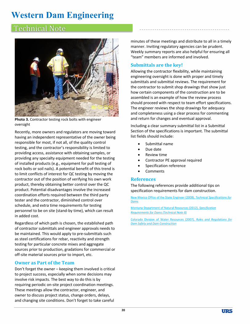
Photo 3. Contractor testing rock bolts with engineer oversight
Recently, more owners and regulators are moving toward having an independent representative of the owner being responsible for most, if not all, of the quality control testing, and the contractor’s responsibility is limited to providing access, assistance with obtaining samples, or providing any specialty equipment needed for the testing of installed products (e.g., equipment for pull testing of rock bolts or soil nails). A potential benefit of this trend is to limit conflicts of interest for QC testing by moving the contractor out of the position of verifying his own work product, thereby obtaining better control over the QC product. Potential disadvantages involve the increased coordination efforts required between the third party tester and the contractor, diminished control over schedule, and extra time requirements for testing personnel to be on site (stand-by time), which can result in added cost.
Regardless of which path is chosen, the established path of contractor submittals and engineer approvals needs to be maintained. This would apply to pre-submittals such as steel certifications for rebar, reactivity and strength testing for particular concrete mixes and aggregate sources prior to production, gradations for commercial or off-site material sources prior to import, etc.
Owner as Part of the Team Don’t forget the owner – keeping them involved is critical to project success, especially when some decisions may involve risk impacts. The best way to do this is by requiring periodic on-site project coordination meetings. These meetings allow the contractor, engineer, and owner to discuss project status, change orders, delays, and changing site conditions. Don’t forget to take careful
minutes of these meetings and distribute to all in a timely manner. Inviting regulatory agencies can be prudent. Weekly summary reports are also helpful for ensuring all “team” members are informed and involved.
Submittals are the key! Allowing the contractor flexibility, while maintaining engineering oversight is done with proper and timely submittals and submittal reviews. The requirement for the contractor to submit shop drawings that show just how certain components of the construction are to be assembled is an example of how the review process should proceed with respect to team effort specifications. The engineer reviews the shop drawings for adequacy and completeness using a clear process for commenting and return for changes and eventual approval.
Including a clear summary submittal list in a Submittal Section of the specifications is important. The submittal list fields should include:
Submittal name
Due date
Review time
Contractor PE approval required
Specification reference
Comments
References The following references provide additional tips on specification requirements for dam construction.
New Mexico Office of the State Engineer (2008), Technical Specifications for Dams
Montana Department of Natural Resources (2012), Specification
Requirements for Dams (Technical Note 8)
Colorado Division of Water Resources (2007), Rules and Regulations for Dam Safety and Dam Construction