poe lighting network lighting solutions for intelligent
TRANSCRIPT

Premise Wiring
PoE LIGHTING Network Lighting Solutionsfor Intelligent Buildings
one solution | one source | one company
One Cable: Power and Control

2 hubbell.com
LED lighting is just one element of an efficient, energy-saving intelligent building system. Building owners and operators expect a robust IoT technology platform that is efficient and scales with technology and operational
advancements. The system must accurately collect building performance data and provide analytics to help make actionable building performance and utilization decisions.
In a PowerHUBB enabled building, a well-designed cabling system is essential to support Internet Protocol (IP) communications and Power over Ethernet (PoE) power delivery to all low voltage sub-systems. This cabling system is designed and constructed to stringent standards with high quality Ethernet communications cables. Use of the highest quality structured cabling components will provide error-free transmission of data from high-bandwidth Wireless Access Points (WAPs) to low-bandwidth building
controllers. Utilize Category 6A intelligent building cabling where possible to future-proof the intelligent building cabling and support emerging high-bandwidth building systems such as 802.11ac and 802.11ax wireless or 4K AV.
Sensors are added to the PowerHUBB lighting system to provide increased energy saving, occupancy comfort and preference control. Occupancy sensors detect when an occupant enters a space and automatically turns lights on, off or adjusts them to lower energy-savings levels based upon predetermined preferences. Ambient light sensors can measure outside light contribution to a space and raise and lower the LED light levels to keep the level at the occupant’s preference. This technology is known as daylight harvesting and can contribute to significant energy savings. The same ambient light sensor can activate motorized window shades and screens. Plug loads such as task lighting can be turned off along with the overhead lights to save even more electrical energy.
The PowerHUBB open Application Program Interface (API) permits the use of third-party sensor, control and temperature solutions customized to building owner needs. The data collected can be ported to building HVAC systems to adjust comfort levels and eliminate separate hard-wired thermostats. Gas sensors can detect hazardous auto exhaust in parking garages and activate exhaust fans. The attachment of power monitoring sensor systems can provide electrical power consumption data for an entire building or individual branch circuits. The intelligent building cabling system can power and gather data from access control systems and surveillance camera systems.
PowerHUBB™: An Internet of Things (IoT) Intelligent Building Platform
The Well-Designed Intelligent Building
BuildingNetwork
WiFi Access Points
Security Cameras
Lighting
Access Control
Plug Load Control
Audio/Video
BMS
Intelligent Building INFRASTRUCTURE

Premise Wiring
3hubbell.com
Power over Ethernet (PoE) is a networking technology that enables safe transmission of DC power and data communication over a traditional twisted-pair networking cable. This technology is an IEEE 802.3 Ethernet standard. PoE is also a Class 2 power distribution strategy and is outlined in Articles 725 and 800 of the 2017 National Electric Code (NEC). PoE power is provided by the Ethernet network switch. Power is combined with data and transmitted from the switch port to selected network end devices (nodes). PoE was developed over fifteen years ago and approved for use by IEEE in 2003. It was first used to power Voice over Internet Protocol (VoIP) digital telephone
systems. PoE eliminated a separate power supply to power the desktop, wall mounted and attendant console telephone sets. In 2009, PoE power increased to 30 watts. Quickly thereafter, the security industry adopted PoE technology to power security cameras and transmit digital video. Today, nearly all 802.11xx commercial Wireless Access Points (WAPs) are powered and networked with PoE cabling infrastructure. PoE enabled Ethernet switches now provide 60 watts of power using technology developed by Cisco. LED lighting systems for commercial use are easily powered with 60 watts. Forthcoming 802.3bt, at close to 100 watts, will further increase system capability.
The primary benifit of PoE is elimination of separate power supplies and additional alternating current (AC) electrical infrastructures to power IP enabled building systems. PoE provides a single-cable solution for power and network connectivity. Readily available network communication cables are the power and communication connectivity medium of choice for intelligent building system end-points.
The LEDs in modern solid state lighting (SSL) systems are direct current (DC) powered digital devices. The traditional LED luminaire is equipped with an AC to DC power converter (driver). This driver converts the building provided AC power to DC power to operate the LEDs. The driver consumes unnecessary electrical energy that is dissipated in the form of heat. Driving the LEDs directly with DC power, as in PoE, provides improved efficiency.
In building design, it is common practice to provide a separate AC power facility for lighting and distribute this AC power to traditional lighting in the ceiling area. This dedicated lighting power delivery system is not required for network PoE lighting systems, reducing the associated material lost.
Lighting controls are required to efficiently operate the LED lighting network and reduce electrical energy consumption. Controlling the LED lights is an obvious network solution. The PoE network cable is the obvious control connection to the network. Adding wireless radios for this control is a redundant network connection. It is a separate IP network path and requires additional power to operate. A robust PoE platform is the most energy efficient solution with interference-free control operation.
What is Power over Ethernet (PoE)?
PoE Simplifies LED Lighting
Power IT
PoE StandardsType Standard Description Power Pairs PSE PD Voltage Date
Type 1 802.3af PoE 2 15 W 13 W 44-57 V 2003
Type 2 802.3at PoE + 2 30 W 25 W 50-57 V 2009
UPOE Cisco Currently in Use 4 60 W 51 W 42.5-57 V 2011
Type 3 802.3bt PoE ++ 4 60 W 51 W 50-57 V Q3 2018
Type 4 802.3bt PoE ++ (4PPoE) 4 ~100 W 71 W 52-57 V Q3 2018
Node
LED Light Fixture
Node to LightPower Connection
PoE Ethernet Switch
Server/Controller Workstation
Switch/Dimmer
Sensor

4 hubbell.com
Cable IT
Intelligent Building Infrastructure
Direct Connection Method
Basic PoE Cabling Architecture
Node
Network Server Horizontal Cable
Direct Connection Method
Horizontal Cable
Patch Panel
Patch Cords
Patch Cord
PoE Ethernet Switch
Equipment Enclosure, Cabinet, Rack
Service Outlet
Light
Node
Light
Traditional Connection Method
Communication cabling systems for buildings were originally designed
to attach computers, printers and telephones to the enterprise network. Network service outlets (SO) and patch cords were provided to permit self-connection to the network by the user.
New intelligent building devices are more
permanent and user administration is a lower priority. With this understanding, standards bodies now allow the “Direct Connection” cabling method. With this cabling scheme the modular plug is installed directly to the end of the horizontal cable and an SO is not required. To facilitate this method of installation Hubbell Premise Wiring provides a field terminating modular plug to speed installation for cabling technicians.
Many of the buildings we see today have communication infrastructure supporting building systems that are disconnected, disparate and expensive to operate.
We are rapidly approaching the time when every low voltage building sub-system will be intelligent, require power and become part of a larger building
network. The worlds of Operation Technology (OT) and Information Technology (IT) are rapidly joining together.
Today we are at a tipping point. We need to consider a more innovative approach. Modern buildings require a scalable intelligent network cabling infrastructure for all IP enabled building systems including wireless, security, video and now lighting. The solution is to plan and design for the future. Intelligent network end-devices require more physical network connections and power. Designs should provide capacity beyond current requirements to simplify future upgrades and better support the fully converged building of the future.
Not all intelligent building systems are the same. The cabling infrastructure must scale with building system technologies, building upgrades and expansion. The correct solution is to design and build a universal IoT ready platform that is easily fitted to current and future technologies. It should not
make a difference if you are connecting LED lights, surveillance cameras, Wi-Fi access points or video displays. All these PoE enabled systems will require an available PoE Ethernet switch port attached to a network, Ethernet cable, Ethernet patch cables and connecting hardware.
BuildingFacilities
Convergence
Planning
OT IT DataNetworks

Premise Wiring
5hubbell.com
Cable IT
Large Scale (Advanced) PoE Cabling Architecture
MISSION CRITICAL® Support
Node
Network Server
Zone Enclosure (ZE)
Zone Enclosure (ZE)Powered
Distributed Ethernernet Switch Required AC Power
Patch Panel
Patch Panel
Patch Cords
Copper or Fiber
PoE Ethernet Switch
Equipment Enclosure, Cabinet, Rack
Light
Node
Light
Node
Light
Patch Panel
PoE Ethernet Switch
Patch Cords
BICSI and RCDD are registered trademarks of BICSI, Inc.
As buildings grow and occupant populations increase, so must the intelligent building scale to meet network demand. A zone cabling architecture is designed to scale. Horizontal Connection Points (HCP) are installed in Zone Enclosures (ZE). A zone architecture provides two benefits. First, it permits installation of the cabling system earlier in the construction cycle before finish work begins. Early installation creates a “light-ready” environment. In ceiling grid environments, lights are simply dropped in the grid and cabled with patch cords. The areas above drop ceilings are normally plenum (return air) spaces, requiring plenum-rated components.
In some situations there may be an advantage to placing Ethernet switches closer to the lights. One
reason to do this is to extend the distance of intelligent building cabling runs. Ethernet switches can be placed in a building zone, freeing up valuable floor space normally dedicated to Telecommunications Rooms (TR). This architecture also increases energy efficiency by reducing voltage drop through the cable. Optical fiber can be used to position the Ethernet switch up to 2km from the primary TR.
The HCP and the Ethernet switch can coexist in the same ZE. They are available in plenum and non-plenum versions. Consult with your Hubbell representative for ZE sizing and styles. AC power is required at the remote Ethernet switch location. This must be accounted for in the planning and design phase of the project.
The design and installation of a functional cabling system for an intelligent building requires qualified designers, integrators and installers. Look for the presence of a BICSI® (bicsi.org) Registered Communication Distribution Designer (RCDD®) on your implementation team.
Hubbell Premise Wiring trains and qualifies its own Certified Installers with such credentials via the MISSION CRITICAL® program. Hubbell certified installations also carry the MISSION CRITICAL® cabling infrastructure warranty which provides a 25-year application assurance guarantee for the entire structured cabling system.

6 hubbell.com
Limited Power (LP) Plenum or Riser Cables
Open Racks | Remote Equipment Enclosures | Networking Cabinets
Surface Mount Panel | Patch Panel | Plenum Zone Enclosure
Jack | Patch Cord | Field Termination Plug
Intelligent Building Cabling Infrastructure Components
Cable IT
Hubbell manufactures a fully integrated system of copper and fiber network cabling and components that are designed to exceed all performance and reliability standards. Hubbell cabling systems are subjected to continuous third party performance verification and carry a full 25-year MISSION CRITICAL® Application
Assurance System Warranty. Hubbell Unshielded Twisted-Pair (UTP) cabling systems are engineered to support the future, including 100W PoE, to assure long term operation with emerging applications such as PoE lighting. For information, visit hubbell-premise.com.
CableHubbell provides specific low energy loss UTP network cables that maximize system efficiency and are UL Listed for Limited Power (LP) delivery.
Racks and CabinetsHPW manufactures a wide array of enclosures and racks that are used to house panels and switches in data centers, closets, or remote areas and zones.
Cross Connect PanelsPatch panels and consolidation points are utilized to simplify labeling and patching over to network switches in Telco Rooms (TR), or work area zones.
Equipment Outlet Jacks, Plugs, and CordsHubbell manufactures everything needed to provide the equipment outlet (EO) to the lighting fixtures. This includes jacks, couplers, field termination plugs, patch cords, housings and plates.

Premise Wiring
7hubbell.com
Network IT
The PowerHUBB™ Network Lighting Solution
The PowerHUBB™ Node
The PowerHUBB network lighting solution is an enterprise-level Power over Ethernet (PoE) lighting and control platform. PowerHUBB seamlessly integrates LED luminaires, sensors, control interfaces and software. It creates a scalable intelligent building IoT platform supporting many low voltage, IP enabled building systems. Design requirements include locating lights in the space, providing a secure area for networking
equipment, determining cable routes, connecting the components and lights, commissioning the system, configuring policies and settings, determining the performance and control data you wish to collect and analyze. It is recommended the PowerHUBB network be isolated from the enterprise network either physically and/or via VLANs.
The PowerHUBB node is the intelligent networking interface component installed between LED lights and the network switch. The node monitors power supplied by the PoE Ethernet switch and distributes the correct power to connected lights. Every light, sensor, and control device attached to the node has a unique identifier assigned to it. The PowerHUBB node is constantly sending and receiving control and sensor data to the network gateway. The node is known as the Powered Device (PD) in a PoE network.
The PowerHUBB nodes permit the connection of several LED lights in a daisy-chain string. There are four versions of the PowerHUBB node. The first node is the Master Node. This node is attached directly to a PoE Ethernet switch port. The second node is the Satellite Node. A Satellite Node can only be connected to a Master Node or to another Satellite Node. Also available are Master
and Satellite Nodes with sensor and control connection points. These nodes are known as “Control Nodes” and are only required where controls and sensors are required in the building space. Only five nodes, of any version, can be connected together on any single cable run and the power draw can not exceed 54 watts.
As soon as PoE power is available the nodes will automatically transfer PoE power to the LED lights and illuminates the LED the spaces to 10%. This occurs even if the network has yet to be fully configured. This provides immediate feedback of any potential cabling issue and provides light during construction. Full functionality and light output will not be available until the system is commissioned.
Maximum 5 Nodes or 54 Watts per Daisy Chain
Maximum PowerHUBB™ Bus Length (30m)
Network Gateway
Patch Panel
PoE Ethernet Switch
Master NodesSatellite Nodes
Master Node with Control
Satellite Node with Control

8 hubbell.com
In addition to the networking function, the PoE switch is the Power Sourcing
Equipment (PSE) for the PoE network. Power from the switch is distributed to the node (PD) via the intelligent building cabling system. The Ethernet switch can be centralized and installed in a cabinet or rack mounted. A
decentralized solution is also supported. Solutions include a wall
mounted or ceiling mounted plenum switch. Patch panels are recommended
with each solution to provide easy administration.
Cisco has a purpose built Digital Building Ethernet switch designed specifically for advanced PoE cabling architecture. The switch is designed for plenum spaces and has no moving parts and robust heat dissipation fins. It is not required to place this switch in a ZE. This switch requires a Cisco remote mount for power. Consult your Hubbell representative for more information.
Midspan permits the utilization of non-PoE switches in PoE lighting networks. The midspan power supply is a standards-based PSE solution. Power is injected into
the network cable between the Ethernet switch and node. A midspan PSE can be used anywhere in the circuit; near the switch or near the node.
Network IT
PoE Switch
Midspan Power
NodeNetwork Server
Patch Panel
MIDSPAN POWER
MIDSPAN POWER
Patch Cords
Horizontal Cable
Light
PoE Ethernet Switch
Patch Panel
Network Server
Patch Panel
Patch Cords
PoE Ethernet Switch
Node
Patch Cord
Patch Cord
Light
Premise Wiring
9hubbell.com
Network IT
Network Gateway
Network Software
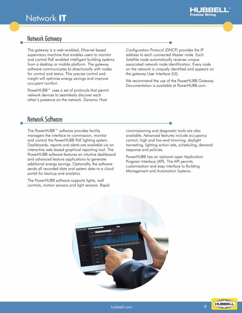
The gateway is a web-enabled, Ethernet based supervisory machine that enables users to monitor and control PoE enabled intelligent building systems from a desktop or mobile platform. The gateway software communicates bi-directionally with nodes for control and status. This precise control and insight will optimize energy savings and improve occupant comfort.
PowerHUBB™ uses a set of protocols that permit network devices to seamlessly discover each other’s presence on the network. Dynamic Host
Configuration Protocol (DHCP) provides the IP address to each connected Master node. Each Satellite node automatically receives unique associated network node identification. Every node on the network is uniquely identified and appears on the gateway User Interface (UI).
We recommend the use of the PowerHUBB Gateway. Documentation is available at PowerHUBB.com.
The PowerHUBB™ software provides facility managers the interface to commission, monitor and control the PowerHUBB PoE lighting system. Dashboards, reports and alerts are available via an interactive web-based graphical reporting tool. The PowerHUBB software features an intuitive dashboard and advanced feature applications to generate additional energy savings. Optionally, the software sends all recorded data and system data to a cloud portal for backup and analytics.
The PowerHUBB software supports lights, wall controls, motion sensors and light sensors. Rapid
commissioning and diagnostic tools are also available. Advanced features include occupancy control, high and low-end trimming, daylight harvesting, lighting action sets, scheduling, demand response and policies.
PowerHUBB has an optional open Application Program Interface (API). The API permits customization and easy interface to Building Management and Automation Systems.

10 hubbell.com
Hubbell offers intelligent devices to support the communication and sensing technologies for simple to complex PoE environments. With a broad offering of
nodes, sensors and user interfaces, PowerHUBB delivers the flexibility to connect and control PoE deployments for smart building solutions.
Controls and Sensors
Light IT
Occupancy/Vacancy Ceiling Mount Sensor• Passive Infrared (PIR), Ultrasonic (US) and Dual Technology (DT) versions• Proprietary adaptive technology eliminates false triggers• Optional relay and photocell control
Low Voltage Sensors
Low Voltage Wall Stations
PowerHUBB™ Nodes• Provide power distribution and data connectivity for
luminaires and control devices• RJ45 ports provided for PoE power and bidirectional
Input/Output (I/O) connections• 1% to 100% dimming range in 1% increments• 54W peak operating power• External sensor/relay and wall switch connections
Occupancy/Vacancy Wall Mount Sensor• PIR and DT versions• Smart adaptive technology eliminates false triggers• Optional relay and photocell control• DT offered in both US with PIR and US with acoustic sensor
Occupancy/Vacancy Wall Switch Sensor• PIR, US and DT versions• Manual-ON (Vacancy Sensor) or Automatic-ON (Occupancy Sensor)• Smart adaptive technology eliminates false triggers• Built-in photo sensor for automatic daylight harvesting• Single or dual relay
Wall Switch Sensor• Supported by I/O connections on PowerHUBB nodes• Offered in 1, 2, 3 and 4 button configurations• Momentary button action• Optional LED indicators available• 24 VDC low voltage device
HCS brochure pg 12
Premise Wiring
11hubbell.com
®
Light IT
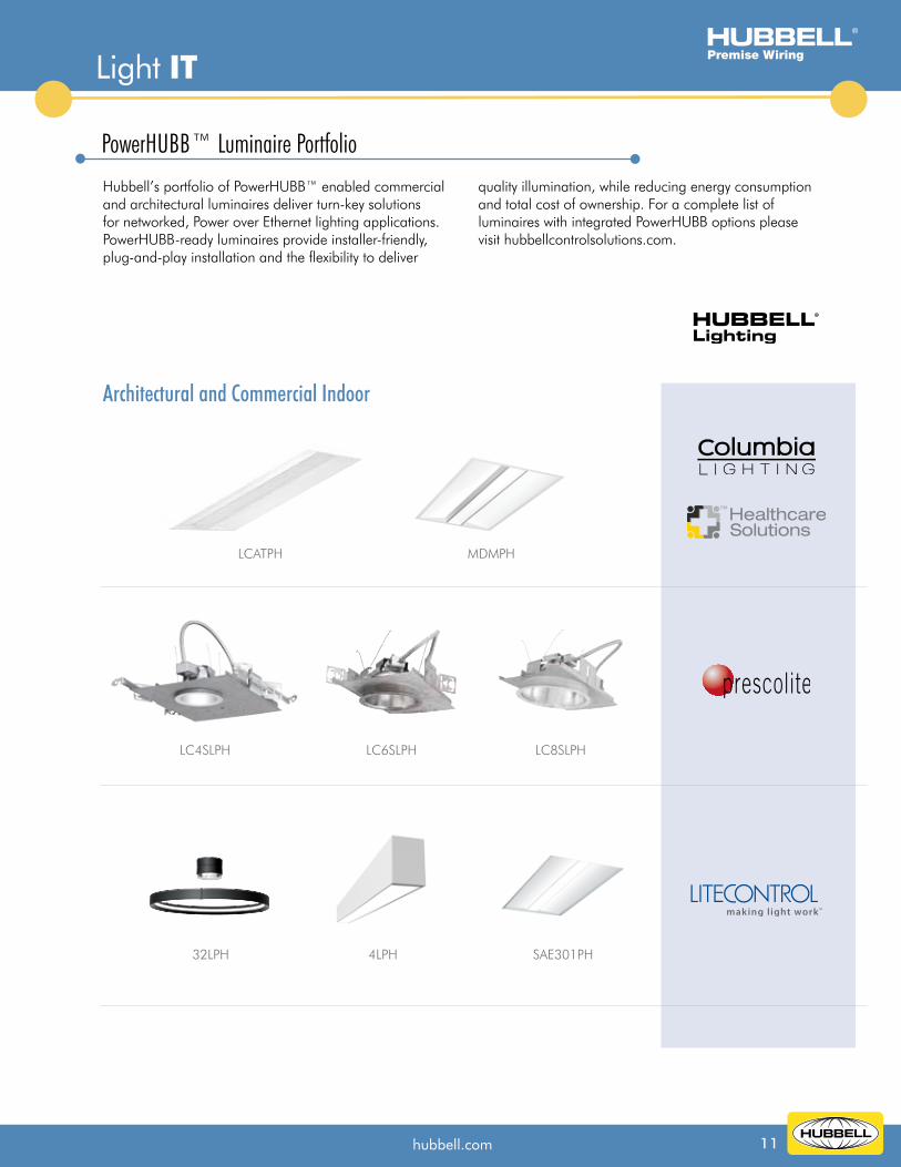
Hubbell’s portfolio of PowerHUBB™ enabled commercial and architectural luminaires deliver turn-key solutions for networked, Power over Ethernet lighting applications. PowerHUBB-ready luminaires provide installer-friendly, plug-and-play installation and the flexibility to deliver
quality illumination, while reducing energy consumption and total cost of ownership. For a complete list of luminaires with integrated PowerHUBB options please visit hubbellcontrolsolutions.com.
Architectural and Commercial Indoor
PowerHUBB™ Luminaire Portfolio
™
4LPH
LCATPH
LC8SLPHLC6SLPHLC4SLPH
32LPH
MDMPH
SAE301PH
Hubbell Incorporated (Delaware) • 40 Waterview Drive • Shelton, CT 06484 • Phone (800) 288-6000 • FAX (800) 255-1031 Printed in U.S.A. Specifications subject to change without notice.® is a registered trademark of Hubbell Incorporated. CLBIB002 2/18
HUBBELL offers a complete complement of products for your PoE Lighting Solution
Related Literature