pocket photodiode geiger counter part no. 2170812 · 2014-01-09 · pocket photodiode geiger...
TRANSCRIPT

Pocket Photodiode Geiger Counter
PART NO. 2170812
A DIY geiger counter that uses a PIN photodiode as a substitute for an expensive Geiger-Mueller tube. It detects alpha and betaradiation particles. The circuit is soldered onto a small protoboard and everything is placed in an aluminum enclosure. Copper tubingand a piece of aluminum foil is used to help filter out noise and RF interference.
Time Required: 3-4 hours depending on experience
Experience Level: Intermediate
Required tools and parts:
Soldering iron and solderAluminum foilElectrical tapeDrillStep drill bitHand toolsJumper wiring3 CR1620 coin-cell batteries, or any coin-cell batteries to add up to 9V2 pieces of copper tubing available at Home Depot: http://www.homedepot.com/h_d1/N-25ecodZ5yc1vZ12kx/R-100343205/h_d2/ProductDisplay?catalogId=10053&langId=-1&keyword=nibco&storeId=10051&superSkuId=202904930#.UKGddGfsZox)
Bill of Materials:
Qty Jameco SKU Component Name
1 1621132 BPW34 PIN photodiode
1 23966 LM358 Dual Op-amp
1 178597 2N3904 NPN Transistor
1 178669 2N7000 Transistor
2 15270 100nF Capacitor
1 597450 100uF Capacitor
1 15229 10nF Capacitor
1 332487 20nF Capacitor
1 691817 10Mohm Resistor
2 691622 1.5Mohm Resistor
1 691286 56kohm Resistor
1 691382 150kohm Resistor
2 2157159 1kohm Resistor
1 255565 250kohm Potentiometer
1 335557 Piezo Buzzer
1 72161 Toggle Switch
2 234923 Crimp pins
1 108338 2-pin Male Header
1 234704 2-Position Housing Connector
1 264990 Potentiometer Knob
1 51626 8-pin IC socket
1 105102 Protoboard
1 2156156 Fliptop Box

Step 1 - Position IC Socket
Since there are quite a few components that need to fit onto this small protoboard. positioning of each component is important. The ICsocket should be around the middle of the board since the pins need to be accessed as you solder. Make sure the notch of the socketis positioned correctly as you want the IC to be placed.
Step 2 - Build Schematic
Follow the schematic paying close attention to the pinouts of the transistors and dual op-amp IC.

Step 4 - Place Resistors (Pins 1 and 2)
Solder each resistor so that they only take up 2 solder holes. The connections are made underneath so make sure you do not shortany of the components by soldering its own leads together.
Step 5 - Back Side of Resistor Connection
Step 3 - Back Side of IC Socket
As you can see from the schematic, pins 1 and 6 are tied together. Soldering the two pins from underneath the board is the best wayto have a clean connection and save space at the same time. This technique will be used throughout the build to keep the entirecircuit compact.

Step 6 - Place 20nF Capacitor
This capacitor is non-polarized. It connects to ground, which I am using as the bus on the protoboard.
Step 7 - Back Side of 20nF Capacitor Connection
Step 8 - Place 10nF Capacitor
This capacitor goes from pin 5 to pin 7. It is non-polarized.

Step 9 - Back Side of 10nF Capacitor Connection
Step 10 - Light Shield Section
The Light Shield section of the schematic is going to be placed in a copper tube to help block out any electromagnetic interferenceand light coming into the photodiode. Soldering the components in a tube-like shape ensures a snug fit into the copper tube. Start byplacing the photodiode on top of the 2N7000 MOSFET and soldering the gate (pin 2) to the anode of the photodiode (without thenotch).
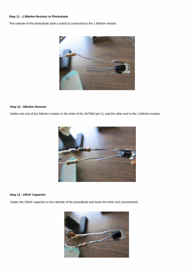
Step 11 - 1.5Mohm Resistor to Photodiode
The cathode of the photodiode (with a notch) is connected to the 1.5Mohm resistor.
Step 12 - 56kohm Resistor
Solder one end of the 56kohm resistor to the drain of the 2N7000 (pin 1), and the other end to the 1.5Mohm resistor.
Step 13 - 100nF Capacitor
Solder the 100nF capacitor to the cathode of the photodiode and leave the other end unconnected.

Step 14 - 10Mohm Resistor
Solder on end of the 10Mohm resistor to the source of the 2N7000 (pin 3), and the other end to the gate of the 2N7000 (pin 2). Add ajumper wire to the source (this will connect to ground), and another jumper wire to the connection between the 1.5Mohm and 56kohmresistors (this will connect to the emitter of the 2N3904 transistor).
Step 15 - Electric tape
Add one more jumper wire to the drain of the 2N7000 (pin 1). This will connect to pin 3 of the dual op-amp IC. To make sure thesesolder connections aren't accidentally shorted, place electrical tape around each lead.

Step 16 - Solder the Light Shield section to the Protoboard
There will be 4 connections made from the Light Shield section to the protoboard: Two connections go to ground, one connectiongoes to pin 3 of the dual op-amp, one connection goes to the emitter of the 2N3904 transistor.
Step 17 - Back Side of Light Shield Connection

Step 18 - Jumper Wire to Pin 3 of Op-amp
Add a jumper wire to connect the Light Shield section to pin 3 of the op-amp. Solder the 2N3904 transistor, connecting the emitter (pin3) to the jumper wire between the 1.5Mohm and 56kohm resistors.
Step 19 - Solder 100uF Cap, 100nF Cap, 150kohm Resistor
Solder the 100uF capacitor, 100nF capacitor and 150kohm resistor to the circuit around the 2N3904 transistor. Pay attention to thepinout of the 2N3904 and the polarity of the 100uF capacitor. There is a small "+" on one side of the capacitor. Connect the other sideto ground.
Step 20 - Back Side of 100uF Cap, 100nF Cap, 150kohm Resistor Connection

Step 21 - Connect Ground Busses
Step 22 - Connect wires to the 250kohm Potentiometer
These wires will make it easier to connect to the protoboard.
Step 23 - Solder Potentiometer to the Board
Solder the 250kohm potentiometer and 1kohm resistor to the protoboard.
Note: The photo shows a 100kohm potentiometer, but was replaced with a 250kohm potentiometer.

Step 24 - Back Side of Potentiometer Connection
Step 25 - Add Buzzer, LED and 1kohm Resistor
Make sure the polarity of the buzzer and LED are correct. The buzzer has a "+" on one end of the sticker, and the longer lead of theLED is connected to the 9V supply.
Step 26 - Back Side of Buzzer, LED, 1kohm Resistor Connection
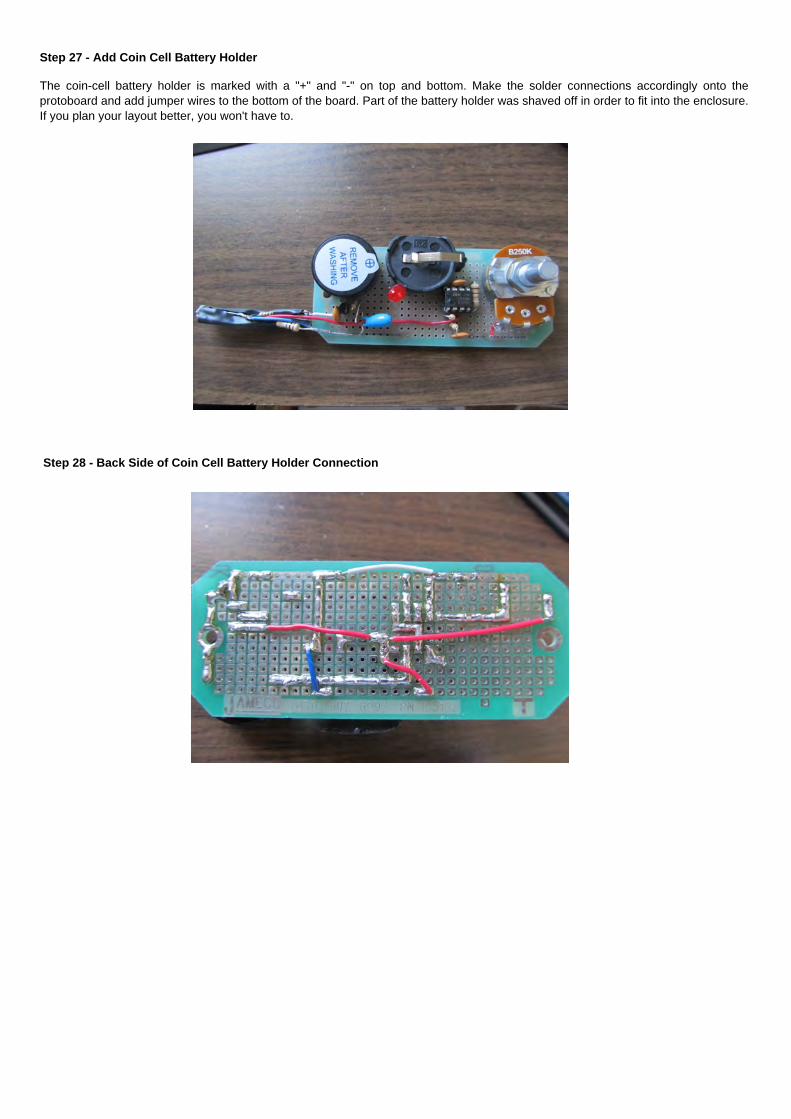
Step 27 - Add Coin Cell Battery Holder
The coin-cell battery holder is marked with a "+" and "-" on top and bottom. Make the solder connections accordingly onto theprotoboard and add jumper wires to the bottom of the board. Part of the battery holder was shaved off in order to fit into the enclosure.If you plan your layout better, you won't have to.
Step 28 - Back Side of Coin Cell Battery Holder Connection

Step 29 - Copper Tube Light Shield
Get the copper tubes and tape them together with some electrical tape. It should be the approximately length of the Light Shieldcircuit and fit snugly.
Step 30 - Drill hole for Light Shield Circuit
Drill a 3/8" hole into the side of the aluminum enclosure where the Light Shield section of the circuit will fit through. Also drill a 1/4"hole on the long side of the enclosure for the toggle switch.
Step 31 - Drill holes for the LED and Potentiometer
Drill a 3/16" hole and 1/4" hole into the lid of the aluminum enclosure for the LED and potentiometer, respectively. Position the boardinto the enclosure and mark the lid before drilling the holes.

Step 32 - Prevent Shorts in the Enclosure
Lay down some electrical tape on the enclosure to prevent any accidental short-circuit connections.
Step 33 - Prepare Toggle Switch
Connect two small pieces of jumper wire with the crimp pins and solder the other ends to the switch. Slide the crimp pins into theheader until it snaps in for a secure fit.
Step 34 - Toggle Switch
Completed toggle switch connection.

Step 35 - Solder 2-pin Header
Solder the 2-pin header to the board for the switch connection.
Step 36 - Insert Switch and Complete Connection
Screw on the toggle switch and insert the socket into the 2-pin header.
Step 37 - Finish
Everything is now electrically connected. Insert the batteries and screw on the lid. I used three stacked CR1620 coin-cell batteries, butyou should be able to use any coin-cell batteries as long as it adds up to 9V. Place the copper tubing over the Light Shield sectionand place tape around the tubing to keep it from moving around. This also keeps light from interfering with the photodiode. Screw theknob onto the potentiometer and you are ready to begin detecting radiation particles.
Note: This should only be used for recreational and entertainment purposes. It is not safe to be around high sources of radiation andthis device should not be used as a reliable source of detecting harmful radiation in the environment.