pneumatic tool monitor tvp-100 series version 1 · pneumatic tool monitor tvp-100 series 4...
TRANSCRIPT

Programming Manual
06/03####-####
Pneumatic Tool MonitorTVP-100 SeriesVersion 1.0
For additional product information visit our website at http://www.coopertools.com
Cooper ToolsP.O. Box 1410Lexington, South Carolina 29071-1410
Cooper Power Tools GmbH & Co.Postfach 30D-73461 Westhausen
AMERICAS EUROPE

Pneumatic Tool Monitor TVP-100 Series
2 25.04.2003
Disclaimer:
The information and data in this document has been prepared to the best of our ability.Nonetheless, differences between the information and the actual product cannot beexcluded with absolute certainty. Cooper Tools does not assume any liability for conse-quential errors and damages. We likewise do not assume liability for damages resultingfrom defective circuitry inside the devices supplied. Cooper Tools reserves the right, toamend, supplement or improve this document or the product without serving priornotice.
Without the express approval of Cooper Tools this document must not be reproduced inits entirety or in part by any means; it must not be converted to any type of natural ormachine readable language or be saved on data storage media of electronic, mechanic,optical or other type.
Pneumatic Tool Monitor TVP-100 Series
325.04.2003
Contents Page1 Getting Started 41.1 Safe Work Practices Symbol 41.2 Checking Your Unit 41.3 Software 41.4 Installing The Unit 41.4.1 General 41.4.2 Mounting 51.4.3 Location Considerations 51.4.4 Source Power 51.5 Connecting Peripherals 5
2 Quick Start Guide 62.1 Powering Up The Unit 62.2 The Ship’s Wheel 62.3 Selecting Tool Type 62.4 Calibration (AutoCal) 72.5 Setting Fasteners Per Batch 82.6 Running The Unit 8
3 Controller Specifications 93.1 Understanding The Keypad 93.2 Specifications 93.2.1 Enclosure 103.2.2 Display 103.2.3 Indicators 113.2.4 AC Input Power 113.2.5 Input/Output Connectors 11
4 Programming 134.1 Run Screen 134.2 Navigation Menu 144.3 AutoCal 144.4 Viewing A Run 154.5 Statistics 164.6 Options 164.6.1 Relay Options 174.6.2 Beeper Options 174.6.3 Application Select Input 184.6.4 Time And Date 194.6.5 Tool Type 204.6.6 Adjusting The Display 204.7 Selecting Application 214.8 Application Builder 214.9 Sequencing 234.7 Administration 234.8 I/O Schematic 24
A Appendix 25A.1 Pneumatic Curves (Pulse Tool) 25A.2 Pneumatic Curves (Direct Drive Tool) 26A.3 Box Dimenstions 274.4 Tool and Box Diagrams 28

Pneumatic Tool Monitor TVP-100 Series
4 25.04.2003
1 Getting Started
1.1 Safe Work Practices Symbol
This “Warning” symbol identifies all notes on safe work practices in this operat-ing instruction, alerting to hazards for life and health of people. Please observethese notes and proceed with special care in the cases described. Pass all safe-ty instructions on to other operators. In addition to the safety instructions inthis operating instruction, the general local safety and accident prevention rulesmust be observed.
The signal word “Caution” identifies all portions of this operating instructionmeriting special attention to ensure that guidelines, rules, hints and the correctwork procedures are observed; and, to prevent damage to and destruction of themachine and/or parts
1.2 Checking Your Unit
Take the time to ensure that you have the required peripheral equipment and cablesnecessary to setup and run your unit. If you do not have all the necessary items,please contact your distributor.
1.3 Software
Your unit has been pre-loaded with its software and requires no additional software tostart monitoring your fastening process. If you are trying to interface this unit to anexternal computer, additional software may be required. Please contact your distribu-tor with inquires about interface software.
1.4 Installing The Unit
1.4.1 General
It is mandatory that national, state, and local safety and wiring standards be fol-lowed during installation. These standards would take precedence over anyinformation presented in this section.
To avoid the hazard of electrical shock or burn, the following instructions mustbe adhered to. Failure to follow these instructions may also cause damage toyour unit and void existing warranties.
• Do not energize the unit until all connections have been properly made.• Equipment must be properly grounded before applying power. Units energizedby cord and plug must be connected to an approved and properly groundedreceptacle• Ensure the power switch is in the “off” position before applying power.
CAUTION!

Pneumatic Tool Monitor TVP-100 Series
525.04.2003
1.4.2 Mounting
Each TVP-100 Series unit is intended to be used as a single tool process monitor in awork station or work area. This unit may be wall mounted, table mounted, beammounted, suspended overhead, pedestal mounted, or used without mounting. Tabshave been provided on the base of this unit to ease this mounting process. Pleasetake care in choosing a stable location for the unit to avoid the possibility of damage tothe unit and/or operator injury through hitting, falling, vibration or inconvenient mount-ing. All cables attached to the unit should be located and secured in a manner toavoid potential operator and passer-by injury. As with all electric equipment, the unitwill produce some heat and should be located so that ambient air can freely circulatearound the box.
1.4.3 Location Consideration
Your unit should be located to allow access to the front panel and connectors. Theunit should be installed for unrestricted and comfortable viewing of the LCD and LED’sby the operator. The LCD menu screen, key pad and side panel connectors must bereadily accessible for the setup. Depending on the peripheral equipment purchased,the unit may be remotely mounted but should still be accessible.
1.4.4 Source Power
This unit is capable of being run off of 110 or 220 VAC (both 50 and 60 Hz).
Before powering up the unit for the first time, take care to notice which voltagethe unit is set up to accept. Damage to the unit may occur if the voltage selec-tion does not match the power that is supplied.
The TVP-100 is fused at 1 Amp.
1.5 Connecting Peripherals
A pressure transducer was supplied with your unit. This transducer needs to be prop-erly connected to the tool that is being monitored and also to this unit. Other inputsand outputs are available for communicating with devices such as PLCs and PCs.Make sure these devices are connected to the proper ports before powering up theunit. Damage can occur to the units if these inputs and output points are used incor-rectly.
To avoid the hazard of electrical shock or burn the following instructions mustbe adhered to. Failure to follow these instructions may also cause damage toyour unit and void existing warranties.
• Ensure the power switch is in the “off” position and that the box cover is properly secured before supplying power to the unit.• Ensure equipment has been properly grounded before applying power.
CAUTION!

Pneumatic Tool Monitor TVP-100 Series
6 25.04.2003
2 Quick Start Guide
2.1 Powering Up The Unit
This quick-start guide assumes that the unit is set up properly, that the unit can bepowered up, and that the transducer is properly attached to the tool being monitoredand this unit. If you need more guidance in any of these areas, please refer to the indepth directions found later in this manual.
2.2 The Ship’s Wheel
When the unit powers up, a splash screen will be displayed momentarily followed bythe main run screen. In order to set up any given tool, press the “ship’s wheel” keyand go to the navigation menu.
2.3 Selecting Tool Type
With the navigation menu showing, use the arrow keys to highlight the “Options” iconand then use the “Enter” key to select “Options”. You may be prompted to enter apassword. If so enter it using the numeric keypad, the default is “0 1 0 4”. At thispoint, the Options Screen will appear. From the Options Screen select the fifth option(Tool Type) by pressing the 5 key. The Tool Type screen will appear at this point. If aCleco Pulse tool is to be monitored, option one (Pulse Pneumatic) should be selected.For all other pneumatic tools option two (Direct-drive Pneumatic) should be selected.
Pressing the “Ship’s Wheel” will return the user to the navigation menu.

Pneumatic Tool Monitor TVP-100 Series
725.04.2003
2.4 Calibration (AutoCal)
Before a tool can be monitored properly, the current application must be set up to mon-itor that tool. The AutoCal option will do this for you automatically. In order to accessthe AutoCal routine, press the “Ship’s Wheel” button and go to the navigation screen.From the navigation screen, use the arrow keys to highlight the AutoCal option andthen press enter.
You may be prompted to enter a password. If so enter it using the numeric keypad.The default password is “0 1 0 4”.
The first screen associated with the AutoCal process will inform the user that the toolmust be off and also that they should press the “Next” key. This screen also remindsthe user which application set is active. The calibration will only effect that application.At this point, make sure the transducer is connected to both the tool and the box andalso that the tool is not running. Then press the “Next” softkey.
The second AutoCal screen will appear next. This screen will prompt the user to run atypical fastener and then to press the “Next” softkey. After these steps are completed,the result of the calibration will appear on the screen.
If the calibration was not successful, you may need to check the tool connection to theunit. On the “Run Screen” there is a portion of the window that shows the active pres-sure within the tool. Check this pressure as the tool is running to see if a change isoccurring. Press the “Ship’s Wheel” to return to the navigation menu.
Please enter your passwordto continue:
Run TypicalFastener
Pneumatic Tool Monitor TVP-100 Series
8 25.04.2003
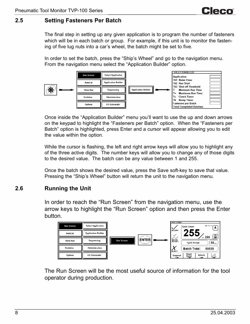
2.5 Setting Fasteners Per Batch
The final step in setting up any given application is to program the number of fastenerswhich will be in each batch or group. For example, if this unit is to monitor the fasten-ing of five lug nuts into a car’s wheel, the batch might be set to five.
In order to set the batch, press the “Ship’s Wheel” and go to the navigation menu.From the navigation menu select the “Application Builder” option.
Once inside the “Application Builder” menu you’ll want to use the up and down arrowson the keypad to highlight the “Fasteners per Batch” option. When the “Fasteners perBatch” option is highlighted, press Enter and a cursor will appear allowing you to editthe value within the option.
While the cursor is flashing, the left and right arrow keys will allow you to highlight anyof the three active digits. The number keys will allow you to change any of those digitsto the desired value. The batch can be any value between 1 and 255.
Once the batch shows the desired value, press the Save soft-key to save that value.Pressing the “Ship’s Wheel” button will return the unit to the navigation menu.
2.6 Running the Unit
In order to reach the “Run Screen” from the navigation menu, use thearrow keys to highlight the “Run Screen” option and then press the Enterbutton.
The Run Screen will be the most useful source of information for the tooloperator during production.
Pneumatic Tool Monitor TVP-100 Series
925.04.2003
3 Controller Specifications
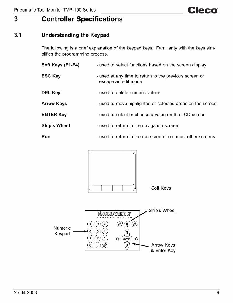
3.1 Understanding the Keypad
The following is a brief explanation of the keypad keys. Familiarity with the keys sim-plifies the programming process.
Soft Keys (F1-F4) - used to select functions based on the screen display
ESC Key - used at any time to return to the previous screen or escape an edit mode
DEL Key - used to delete numeric values
Arrow Keys - used to move highlighted or selected areas on the screen
ENTER Key - used to select or choose a value on the LCD screen
Ship’s Wheel - used to return to the navigation screen
Run - used to return to the run screen from most other screens
Soft Keys
Ship’s Wheel
Arrow Keys& Enter Key
NumericKeypad

Pneumatic Tool Monitor TVP-100 Series
10 25.04.2003
3.2 Specifications
3.2.1 Enclosure
• Height 9.125 in./232 mm• Width 8.75 in./222 mm• Depth 4.125 in./105 mm• Weight 6 lbs/2.72 kg• Removable Fuse Compartment• Settings for 110/220 VAC 50/60Hz• Exposed I/O Strip
3.2.2 Display• 320 x 240 LCD• LED Backlight• Adjustable Contrast

Pneumatic Tool Monitor TVP-100 Series
1125.04.2003
3.2.3 Indicators
3 Highly Visible Indicators
3.2.4 AC Input Power
• Selectable 115 VAC or 230 VAC Power• Fuse access in power entry module• Spare fuses inside power entry module• Unit fused at 1Amp
3.2.5 Input/Output Connectors
• RS-232 Connection RJ12 (6-Conductor Phone)• I/O Connector Pheonix 1757569 • Transducer Connection RJ12 (6-Conductor Phone)
Cycle Accept - Green
Batch Accept - Green
Reject - Red
Power EntryModule
Voltage SelectionWindow
Fuses and SparesLocated InsideModule

Pneumatic Tool Monitor TVP-100 Series
12 25.04.2003
3.2.5 Input/Output Connectors (continued)
RS-232 SerialConnector
12-Pin I/OConnector
PressureTransducerConnector
PIN # Description Value
RS-232 Serial Port (RJ12)
1 UNUSED N/A
2 UNUSED N/A
3 RX (Receive) -25V to +25V
4 TX (Transmit) -25V to +25V
5 GND 0V
6 UNUSED N/A
PIN # Description Value
Pressure Transducer Port
1 Power Out +5 VDC
2 Analog Pressure IN 0V to 5V
3 RS-485+ -1V to 6.5V
4 RS-485- -1V to 6.5V
5 GND 0V
6 UNUSED N/A
PIN # Description Value
12-Pin Pheonix Input/Ouput Connector
1 RS485- -1V to 6.5V
2 RS485+ -1V to 6.5V
3 Reject Relay Output +24VDC
4 Batch Relay Output +24VDC
5 Cycle Relay Output +24VDC
6 +24VDC OUT/Relay Common +24VDC
7 Ground/Opto Common 0VDC
8 Reset Optically Isolated Input 0V to 24V
9 Suspend Optically Isolated Input 0V to 24V
10 Parameter B Optically Isolated Input 0V to 24V
11 Parameter C Optically Isolated Input 0V to 24V
12 Parameter D Optically Isolated Input 0V to 24V
RS485-
RS485+
REJ RLY
BAT RLY
CYCL RLY
RLY COM
OPTO COM
RST IN
SUSP IN
PRMB IN
PRMC IN
PRMD IN
RS-485 Comm Buffer
+24VDC
JP5
JP3
1.5K
1.5K
1.5K
1.5K
1.5K

Pneumatic Tool Monitor TVP-100 Series
1325.04.2003
4 Programming
4.1 Run Screen
The Run Screen is the main screen that will be used while the tool is in operation.This screen contains a wealth of information about what is occurring in the assemblyprocess at any given time. From this screen a user can ascertain how many fastenershave been completed towards a batch, the current application, the last fastener status,the pressure within the tool, whether the unit is locked or un-locked, and the total num-ber of batches that have been completed.
This screen automatically appears at the end of the power up sequence. This screenmay also be reached by selecting the “Run Screen” option from the navigation menu.
Number CompletedToward Batch Number in Batch
Application in Use
Lock State
Pressure InsideTool
Soft Key Functions
Number ofComplete Batches
CurrentStatus
LED IndicatorFunctions

Pneumatic Tool Monitor TVP-100 Series
14 25.04.2003
4.2 Navigation Menu
The Navigation Menu is the leaping off point to all functions within this unit. The Ship’sWheel key may be pressed at any time, and the Navigation Menu will appear. Fromthe Navigation menu, the user can go to the Run Screen, perform an AutoCal, view arundown, review statistics, set the units options, select the application in use, adjustany given application, enable sequencing, perform administrative functions, and look ata schematic that aids in external wiring.
4.3 AutoCal
In order for this unit to function properly, the thresholds and timers within the applica-tion need to be set appropriately with regards to the tool’s pneumatic signature. TheAutoCal feature provides a very quick and easy means of performing this set-up. Toreach the AutoCal function, select “AutoCal” from the navigation menu.
If the unit was locked prior to making this selection, you’ll be prompted to enter thepassword. The default password is “0 1 0 4”.
The first screen associated with the AutoCal process will inform the user that the toolmust be off and also that they should press the “Next” key. This screen also remindsthe user which application set is active. The calibration will only effect that application.At this point, make sure the transducer is connected to both the tool and the box andalso that the tool is not running. Then press the “Next” softkey.
Please enter your passwordto continue:

Pneumatic Tool Monitor TVP-100 Series
1525.04.2003
4.3 AutoCal (continued)
The second AutoCal screen will appear next. This screen will prompt the user to run atypical fastener and then to press the “Next” softkey. When running a “typical” fasten-er, the user should start with the tool off and then run the fastener to its completionallowing the tool’s clutch to turn the tool off. The tool’s trigger should then be releasedand left alone until the “NEXT” softkey is pressed on the unit.
After these steps are completed, the result of the calibration will appear on the screen.
If the calibration was not successful, check the tool and transducer connections. Thetransducer needs to be properly connected to both the tool and this unit in order for thesystem to function correctly.
The Run Screen may be used to determine if a pressure change is occurring while thetool is running. When the tool if off, the pressure should be near to if not 0 psi. Whilethe tool is running, the pressure will be around 50 or 60 psi. When the clutch shuts thetool off, the pressure will rise almost to line pressure.
It’s also very important that the appropriate tool type is selected. Pulse tools and directdrive tools are monitored differently. Be sure that the appropriate tool has been select-ed under the Options screen.
4.4 Viewing A Run
A graph of the last run down may be viewed by selecting the “View Run” option fromthe navigation menu. Once again, you may be prompted to enter a password if theunit has not been un-locked.
While viewing a run, the “1” key may be pressed to draw and erase the thresholds andtimers. Pressing the “2” key will draw and erase the tool’s signature. If a new fasten-ing cycle is run, the “ENTER” key may be pressed to retrieve and view this new curve.
Run TypicalFastener

Pneumatic Tool Monitor TVP-100 Series
16 25.04.2003
4.5 Statistics
This unit will hold information pertaining to the last 1000 events. That information canbe viewed by going to the “Statistics” screen. In order to reach the “Statistics” screen,highlight the Statistics option on the navigation menu and press “ENTER”.
There are five columns worth of information on the Statistics screen. Column oneholds the event number. The second column displays the application the unit wasusing when that event occurred. The date and time that the even occurred is dis-played in column three and column four. Column five holds a description of the eventitself. The event description will be a Cycle OK, a Batch OK or a Reject.
The Cycle OK status tells you that a single fastening was completed properly. A BatchOK tells you that a single fastening was completed properly and that it was the lastfastener in the batch. A Reject status informs the user that for some reason that fas-tening was rejected. Each Reject status is accompanied with a reason to help you dis-cern why that fastening was rejected.
The soft-keys provide functions that allow a user to view more statistics than can beshowed on the screen at one time. The “Page Up” and “Page Down” soft-keys can bepressed to view events that occurred further back in time or more recently. Pressingthe “Most Recent” soft-key will place the most recent event at the top of the screenand the events that preceeded it directly below.
Pressing the “Exit” soft-key or the Ship’s Wheel will take the unit back to the navigationmenu.
4.6 Options
Several user adjustable features can be accessed from the “Options” menu. In orderto reach the “Options” menu, highlight the Options button on the navigation menu andpress the “ENTER” key.

Pneumatic Tool Monitor TVP-100 Series
1725.04.2003
4.6.1 Relay Options
The first item on the Options screen list is Relays. By selecting this option the usercan choose to set the relays to “latching” or “momentary”. To select “Relays” from theOptions screen list either press the “1” key or highlight the “Relays” option and press“ENTER”
Once at the “Relays Options” screen you can choose how the relay outputs are goingto act. If the relays are set to momentary, each time an event occurs the correspon-ding relay will turn on for 200ms and then turn back off. If the relays are set to latch-ing, the appropriate relay will turn on and remain on when an event occurs. That relaywill turn back off at the beginning of the next cycle (the next time the tool starts).
To make a selection on this screen, the number key that corresponds with the selec-tion may be pressed. If you use this number key method, the selection will be madeand stored. The screen will also return to the “Options” menu.
A selection may also be made by using the arrow keys or the “UP” and “DOWN” soft-keys to highlight the desired selection and then pressing the “Select” soft-key.
The “EXIT” soft-key, the “Ship’s Wheel”, or the “ESC” key may be pressed to return tothe “Options” screen without making and storing a new selection.
4.6.2 Beeper Options
The second item on the Options screen list is Beeper. The unit can be programmed todouble-beep or be silent upon the completion of a batch. In order to choose theBeeper option either press the “2” key or highlight the Beeper option using the Arrowkeys and then press “ENTER”

Pneumatic Tool Monitor TVP-100 Series
18 25.04.2003
4.6.2 Beeper Options (continued)
To make the box double-beep on a batch accept, either press the “1” key at theBeeper Options screen or highlight the “Double Beep” option and press the “Select”soft-key.
If a double-beep is not desired either press the “2” key at the Beeper Options screen orhighlight the “Beeper on Reject” option and press the “Select” key.
4.6.3 Application Select Input
Applications can be select through external inputs. These inputs can be used in twodifferent schemes. The inputs can either select one of four different applications. Or,when set to “binary”, these three inputs can be used to select eight different inputs.
Binary (1 of 8) is the first option on the “Applications Select Inputs” screen. In order tochoose this option either press the “1” key at this screen or highlight the option andpress the “Select” soft-key.
If discrete (1 of 4) is how you would prefer to select applications either press the “2”key or highlight this option and press the “Select” soft-key.
Param D Param C Param B Application Application INPUT INPUT INPUT (Binary) (Discrete)OFF OFF OFF A AOFF OFF ON B BOFF ON OFF C COFF ON ON D CON OFF OFF E DON OFF ON F DON ON OFF G DON ON ON H D

Pneumatic Tool Monitor TVP-100 Series
1925.04.2003
4.6.4 Time and Date
This unit will keep track of the current time and date even when the unit is turned off.Each time an event occurs (like an accept or reject), that event is stored in memoryalong with a time and date stamp.
The time and date may be edited by pressing the “4” key at the Options screen or byhighlighting the “Time / Date” element and pressing the “Select” soft-key.
Once at the TIME / DATE edit screen, the left and right arrows may be used to select acharacter within the time or date. Once the desired character is highlighted the num-ber keys may be used to alter its value.
Once the time and date are set to the desired value, either the “Save” soft-key or the“ENTER” key may be pressed to save the new value. If a new value is saved, the unitwill have to be powered down and powered back up again before the changes takeeffect.
To leave the TIME / DATE screen without making any changes either the “EXIT” soft-key or press the “ESC” key.

Pneumatic Tool Monitor TVP-100 Series
20 25.04.2003
4.6.5 Tool Type
It’s very important to select the correct tool type for the application. There are two dif-ferent choices for monitoring tools within this unit. The first choice is Pulse Pneumaticand should be used for monitoring Pulse Tools. When set to Pulse Pneumatic, thisunit will not only use the timers and thresholds. This unit will actually count and con-firm that a certain number of pulses occurred.
The Direct-drive Pneumatic is used for monitoring pneumatic clutch tools that do notpulse.
To set Tool Type, from the Options Screen select the fifth option (Tool Type) by press-ing the 5 key or highlight the option and press “ENTER”. The Tool Type screen willappear at this point. If a Pulse tool is to be monitored, option one (Pulse Pneumatic)should be selected. For all other pneumatic tools option two (Direct-drive Pneumatic)should be selected.
Pressing the numeric key associated with the desired option (either “1” or “2”) willselect and write that option to memory. Alternatively, your option can be highlightedand then “ENTER” can be pressed to make a selection.
4.6.6 Adjusting The Display
The unit’s display is set for optimal viewing at the factory. However, it may be neces-sary at some point to make the display darker or lighter for easier viewing. If the dis-play needs adjusted, option six can be selected from the Options menu by eitherpressing the “6” key or by highlighting the option and pressing “ENTER”.
The arrow keys are used to alter the display from the Adjust Display screen. Once thedisplay has the desired appearance, press the “EXIT” soft-key to return. The defaultLCD values can be re-written if the “.” button is pressed during the power-up screen orat the “Run” screen.

Pneumatic Tool Monitor TVP-100 Series
2125.04.2003
4.7 Selecting Application
An application is a set of parameters that governs how a given tool is monitored. Thereare two different ways to choose which application is in use. One way is throughexternal inputs. The other method can be accomplished through the keypad. A dip-switch inside the box controls which method can be used.
If dip-switch one on the backboard is in the “ON” position, then applications can beselected through the keypad. In order to change the application, go to the navigationmenu and choose “Select Application”.
On the “Select Application” screen, an arrow will point to indicate which application iscurrently selected. To change this selection, you can press the number on the keypadthat is associated with the application you want to select. Or, you can highlight thedesired selection with the arrow keys and then press the “Select” soft-key.
To leave this screen without making any changes, the “EXIT” soft-key can be pressedor the “ESC” key can be pressed. The “Ship’s Wheel” has no effect at this screen.
4.8 Application Builder
An application is a set of timers, thresholds, and a batch value that are used in moni-toring the pneumatic tool. The best way to develop these values it to make use of theAutoCal feature. By using AutoCal, the timers and thresholds will be generated auto-matically for any given application.
A situation may arise where these values need to be manipulated manually. If so,select the “Application Builder” option from the navigation menu. This action will takethe unit to the “Application Builder” screen.

Pneumatic Tool Monitor TVP-100 Series
22 25.04.2003
4.8 Application Builder (continued)
To edit an item from the Application Builder, highlight the item you want to edit andthen press “ENTER”. A cursor will appear. While that cursor is highlighting a digit, usethe numeric keypad to alter its value or use the left and right arrows to select a differ-ent character.
The “ESC” key will stop the cursor from flashing and allow you to select a different ele-ment to be edited.
The “SAVE” soft-key must be pressed in order to save any changes made within theApplication Builder. The “EXIT” soft-key will allow a user to leave the ApplicationBuilder without making any changes.
The “Globalize” soft-key allows you to copy an application to all of the other applica-tions.
The “Clear Total” soft-key sets the total back to zero.
Application Element Description:Th1 Noise Floor Pressure threshold that sets a pressure level for the unit to begin
capturing data
Th2 Run Start Pressure threshold that sets a pressure level which after crossed a status will be generated (either accept or reject).
Th3 Shut-off Threshold Pressure threshold that sets a pressure level above which the tool isconsidered to have “clutched” out.
T- Minimum Run Time Minimum amount of time the tool must run before clutching out without generating a reject.
T+ Maximum Run Time Maximum amount of time tool can run before clutching out without generating a reject.
Tc Clutch Timer Amount of time user must hold tool trigger after tool clutches out without generating a reject.
Tb Timer Bump Timer used to cancel incidental runs in the case of a push to start tool. If this timer is violated without the clutch firing, no status will be generated. AutoCal sets this timer to 0.
Fasteners per Batch Number of fasteners associated with a batch. Every time this number of fasteners is completed, a Batch Accept will be generated.
Total Completed Batches This number represents the number of batches that have been completed.

Pneumatic Tool Monitor TVP-100 Series
2325.04.2003
4.9 Sequencing
This unit has the ability to automatically switch from application to application if the“Sequencing” feature is enabled. If Sequencing is enabled, the unit will start inApplication A. Once the batch is complete in Application A, the unit will automaticallyswitch to Application B. This switching from application to application will continueupon the completion of each batch until the end application is reached.
Once the end application is reached and the batch is completed, a batch accept will begenerated and the unit will revert back to Application A. The batch accept output willonly be generated on the final application in the sequence.
In order to program the Sequence function, select the “Sequencing” item from the navi-gation menu.
Using the arrow keys or the “UP” and “DOWN” soft-keys, you can highlight the type ofsequencing you wish to employ. Once the desired selection is highlighted, pressingthe “Select” soft-key will move the arrow to indicate that the selection has changed.
The “EXIT” soft-key, the “ESC” key, and the “Ship’s Wheel” will all take the unit back tothe navigation menu.
4.A Administration
The unit’s password can be altered from the Administration screen. To alter the unit’spassword, choose “Administration” from the navigation menu. There are only twooptions on the Administration screen, one is “Change Password” and the other is“Exit”. Choose the “Change Password option by highlighting it and pressing the“ENTER key.

Pneumatic Tool Monitor TVP-100 Series
24 25.04.2003
4.A Administration (continued)
After “ENTER” is pressed, a screen will appear prompting you to enter a new four-digitpassword. Use the numeric keypad to enter this new code or press the “Exit” soft-keyto escape without changing the password.
Once the new four-digit code is entered, the unit will prompt you to confirm this fourdigit code. If you enter the same code the second time, the unit will politely ask you toremember your new password. If for some reason the same code is not entered twice,the unit will inform you that your confirmation failed.
In either case, after a short delay, the unit automatically returns to the navigationmenu.
4.B I/O Schematic
The final option on the navigation menu is “I/O Schematic” if this option is selected aschematic appears on the screen which shows the function of the 12-pin I/O connectorand the circuitry behind it.
Pressing any key while the schematic is being displayed will return the unit to the navi-gation menu.

Pneumatic Tool Monitor TVP-100 Series
2525.04.2003
A AppendixA.1 Pneumatic Curves (Pulse Tool)
Good Run Down:The picture to the leftshows the analog data froma good fastening processusing a pulse tool. Thereare a few hallmarks in thiscurve that are worth notic-ing. This tool was set up topulse at least four times. Ifthe tool does not pulse atleast four times, there is agood chance that it will gen-erate reject statuses.
Also, at the end of thepulsing phase, the pressuresteps up almost to linelevel. This region indicatesthe tool’s clutch shut thetool off when torque wasachieved.
Incomplete Run Down:
This picture shows the curve generated by anincomplete fastening process. Notice how thecurve does not step up to line pressure at theend of the run. This indicates that the clutchdid not engage.
Double-Hit:
This picture show the curve generated by adouble hit. Notice how the curve immeadiatelysteps up to line pressure and stays there.There is little or no pulsing region. This curvewould be typical of a fastener being “hit” againafter the fastener had already been tightened totorque.
Pulsing Region
Clutch-OutRegion
Free Run

Pneumatic Tool Monitor TVP-100 Series
26 25.04.2003
A AppendixA.2 Pneumatic Curves (Direct Drive Tool)
Good Run Down:The picture to the leftshows the analog data froma good fastening processusing a direct drive tool.There are two hallmarks inthis curve worth noticing.First, during free run thetool runs at a constant pres-sure which is lower than theshut-off or clutch-out pres-sure. Then, after to tool’sclutch engages the pres-sure steps up to near linepressure.
Incomplete Run Down:
This picture shows the curve generated by anincomplete fastening process. Notice how thecurve does not step up to line pressure at theend of the run. This indicates that the clutchdid not engage.
Double-Hit:
This picture show the curve generated by adouble hit. Notice how the curve immeadiatelysteps up to line pressure and stays there.There is no free run region. This curve wouldbe typical of a fastener being “hit” again afterthe fastener had already been tightened totorque.
Clutch-OutRegion
Free Run

Pneumatic Tool Monitor TVP-100 Series
2725.04.2003
A AppendixA.3 Box Dimensions

Pneumatic Tool Monitor TVP-100 Series
28 25.04.2003
A AppendixA.4 Tool and Box Diagram