pneumatic tie rod style cylindersparkercylinderdistributor.com/catalogs/hy08-0915.pdf · pneumatic...
TRANSCRIPT

aerospaceclimate control electromechanicalltrationuid & gas handlinghydraulicspneumaticsprocess controlsealing & shielding
Pneumatic Tie Rod Style CylindersSeries MA / MAN NFPA Industrial Air Cylinders

Pneumatic Tie Rod Style CylindersSeries MA / MAN
Parker Hannifin CorporationCylinder DivisionDes Plaines, Illinois USAwww.parker.com/cylinder
Catalog HY08-0915-1/NA
2
In line with our policy of continuing product improvement, specifications and information contained in this catalog are subject to change.Copyright ©2015 by Parker Hannifin Corporation. All rights reserved.PRINTED IN THE U.S.A.
WARNINGFAILURE OR IMPROPER SELECTION OR IMPROPER USE OF THE PRODUCTS AND/OR SYSTEMS DESCRIBED HEREIN OR RELATED ITEMS CAN CAUSE DEATH, PERSONAL INJURY AND PROPERTY DAMAGE.This document and other information from the Parker Hannifin Corporation, its subsidiaries and authorized distributors provide product and/or system options for further investigation by users having expertise. It is important that you analyze all aspects of your application, including consequences of any failure and review the information concerning the product or system in the current product catalog. Due to the variety of operating conditions and applications for these products or systems, the user, through its own analysis and testing, is solely responsible for making the final selection of the products and systems and assuring that all performance, safety and warning requirements of the application are met.
The products described herein, including without limitation, product features, specifications, designs, availability and pricing, are subject to change by Parker Hannifin Corporation and its subsidiaries at any time without notice.
Offer of SaleThe items described in this document are hereby offered for sale by Parker Hannifin Corporation, its subsidiaries or its authorized distributors. This offer and its acceptance are governed by provisions stated on a separate page of the document entitled ‘Offer of Sale’.

Pneumatic Tie Rod Style CylindersSeries MA / MAN
Parker Hannifin CorporationCylinder DivisionDes Plaines, Illinois USAwww.parker.com/cylinder
Catalog HY08-0915-1/NA
1
Table of Contents
2
3
4-5
6
Product Design
Specifications / Mounting Styles
Cylinder Features
Rod End Dimensions 1-1/2 to 5" Bore
Mounting Styles 1-1/2 - 5" Bore
6
7
Tie Rod Mounting Styles T, TB, TC and TD
Flange, Side and Pivot Mounting Styles H, J, C, F and BB
Trunnion Mounting Styles D, DB and DD 8
Mounting Styles 6" Bore
9
9
9
10
Tie Rod Mounting Styles T, TB, TC and TD
Flange Mounting Styles H and J
Side Mounting Styles C and F
Pivot Mounting Style BB
Trunnion Mounting Styles D, DB and DD 10
11
12
13
14
15
16
17
18
19
20
21
22
23
Double Rod Models 1-1/2" to 6" Bore
Push and Pull Forces
Stop Tubing / Mounting Classes
Cylinder Stroke Chart
Cylinder Accessories
How to Order
Model Numbers, How to Develop and Decode Them
Magnetically Actuated Switches
Switch Mounting Data and How to Order Switches
Switch Connectors
Parts Identification and Seal Kits
Service Kits & Replacement Parts
Manufacturing Locations
Cylinder Safety Guide
Offer of Sale
24-25
26
Table of Contents

Pneumatic Tie Rod Style CylindersSeries MA / MAN
Parker Hannifin CorporationCylinder DivisionDes Plaines, Illinois USAwww.parker.com/cylinder
Catalog HY08-0915-1/NA
2
Series MA / MAN Pneumatic Tie Rod CylindersThe No-Compromise Design NFPA Air Cylinder from ParkerProven Parker reliability at a cost that makes it right for your air cylinder application.
Series MA for filtered and lubricated compressed airSeries MAN for filtered and dry compressed air • 200 psi nominal air pressure • Standard bore sizes: 11/2", 2", 21/2", 31/4", 4", 5" and 6" • 11 Standard mounting styles
Exclusive with the New Parker Check Seal Cushions: • Faster Cycle Time • Easy Precision Adjustment • Minimum Wear • Low Pressure Drop
Product Design

Pneumatic Tie Rod Style CylindersSeries MA / MAN
Parker Hannifin CorporationCylinder DivisionDes Plaines, Illinois USAwww.parker.com/cylinder
Catalog HY08-0915-1/NA
3
Specifications / Mounting Styles
Parker Series MA / MAN air cylinders meet or exceed NFPA Pneumatic Standards and except for Tie Rod Mount Styles conform to ANSI/(NFPA) T3.6.7R3 - 2009 for mounting dimensions of Square Head Industrial Fluid Power Cylinders.
• Seven bore sizes – 11/2" through 6"• Three rod diameters – 5/8", 1" and 13/8"• Eleven mounting styles• Choice of three rod end styles• Cushions at head, cap or both ends• Double rod models in six mounting styles
• JIC interchangeable• Standard Temperature – -10°F to +165°F with standard
seals; -10°F to +250°F with fluorocarbon seals.For complete ordering information see the How to Order and Model Number pages.
Available Mountings
Double Rod Cylinders
Style KTB
See Double Rod Models page for styles available.
Standard Specifications
Parker Series MA / MANNFPA Industrial Air Cylinders
For heavy-duty applications see the Parker Series 2A HY08-0910 Catalog.
Tie Rods Extended Head End Tie Rods Extended Cap End Tie Rods Extended Both Ends Cap Fixed Clevis
Style TB Style TC Style TD Style BB NFPA MX2 NFPA MP1
Head Rectangular Flange Side Lugs Cap Rectangular Flange Side Tapped
Style J Style C Style H Style F NFPA MF1 NFPA MS2 NFPA MF2 NFPA MS4
Head Trunnion Cap Trunnion Intermediate Trunnion
Style D Style DB Style DD NFPA MT1 NFPA MT2 NFPA MT4

Pneumatic Tie Rod Style CylindersSeries MA / MAN
Parker Hannifin CorporationCylinder DivisionDes Plaines, Illinois USAwww.parker.com/cylinder
Catalog HY08-0915-1/NA
4
Cylinder Features
Hard chrome-plated and polished piston rod of 100,000 psi yield, high tensile strength steel for reliable performance and long rod seal life, less friction.
Parker Series MA / MANThe inside story on the no-compromise designHere’s an inside look at the solid design and construction that makes Parker Series MA / MAN the high performing, longer-lasting, economical choice for your air cylinder applications.
Parker’s New Exclusive Check Seal CushionsFor Increased Productivity and Maximum PerformanceThe Parker check seal cushion is new and different from ordinary cushion designs. It combines the sealing capabilities of a lipseal for efficient capture of air for effective cushioning with check valve action for quick stroke reversal.
The lipseal design also provides “floating cushions” to assure cushion repeatability and long life. At the start of the stroke in each direction, the check valve design allows full fluid flow to piston face with a minimum pressure drop for maximum power stroke.
Additional benefits of the new check seal cushions are increased productivity and top performance for faster cycle time, minimum wear, easy adjustment and low pressure drop.
Rugged square steel heads and caps resist shock and provide maximum strength within minimum space. Factory-treated to resist corrosion.
High strength piston rod end stud (125,000 psi minimum yield steel) with rolled threads. Choice of male or female thread at no extra cost. Anaerobic adhesive is used to permanently lock the stud to the rod.
Bolt-on, high strength, rod gland removes screwdriver-easy on all mounting styles and bore sizes for fast, on-the-job rod seal replacement if needed.
Extra long inboard bearing surface insures lubrication from within the cylinder for longer life.
Factory prelubrication of rod and piston seal surfaces (rod bearing and cylinder bore surfaces).
Piston rod lipseal/wiper combination is completely self-compensating for zero leakage at all pressures. Keeps pressure in, contamination out.
Ports N.P.T.F. ports are standard.
Tie rods are 100,000 psi minimum yield steel with rolled threads for added strength. High strength nuts provide extra margin of safety.
The basic cushion design is optional and available on either the head end, cap end or both ends without change in envelope or mounting dimensions. A cushion adjusting needle is supplied for easy, precise adjustment on all bore sizes.
At the head end of the cylinder, the check seal is assembled into a groove in the central bore of the head, with the groove being slightly wider and larger in diameter than the check seal, so that it floats laterally and radially within predetermined limits. The check seal has four grooves molded into the face to provide flow passages; the assembly is put together with the lip of the seal facing toward the inside of the cylinder.
A cushion sleeve is mounted on the piston rod, so that as the rod extends, air ahead of the piston flows freely out the head-end port. When the end of the cushion sleeve reaches the lip of the check seal, it seals on the wall of the groove, trapping air for cushioning.
As pressure is applied to the head-end port on retraction, the air forces the seal towards the inside of the cylinder.

Pneumatic Tie Rod Style CylindersSeries MA / MAN
Parker Hannifin CorporationCylinder DivisionDes Plaines, Illinois USAwww.parker.com/cylinder
Catalog HY08-0915-1/NA
5
Cylinder Features
Aluminum Alloy cylinder body with corrosion resistant smooth hard coated bore on 11/2" and 2" bores.Chrome Plated Steel Tubing honed to a 15 micro inch finish on 21/2", 31/4", 4", 5" and 6" bores (cylinders supplied with reed switches are equipped with aluminum barrels).
Cylinder body O-ring seals are pressure-actuated for positive sealing. Commercially available and easily replaced, if necessary.
Unique “check seal” cushions with molded flow passages combine the benefits of floating cushions with check valve action, provides effective cushioning and quick stroke reversal for more cycles per hour and higher production rates. Cushion needle valves make precise adjustment quick and easy.
Longest standard cushions in the industry for maximum cushioning capability.
Fully dynamic, self-compensating Lipseal™ piston seals designed for no-leak service at all operating pressures; easily replaced, if needed, without removing piston from rod.
One-piece, nodular iron piston, positively locked to rod – retains lubrication and provides a wide bearing surface. An anaerobic adhesive is used to permanently lock and seal the piston to the rod.Piston-to-rod thread diameter increases with rod diameter for added strength and is equal to outer end Style 4 thread on all rod sizes.
The air then flows around the OD of the seal and through the flutes of the seal washer. Full-flow, quick starts with little or no pressure drop is just one of the major benefits of the design.At the cap end of the cylinder, the check seal is assembled into a cavity in the face of the cap with four beads molded on the OD to provide a flow passage. A fluted washer and retaining ring, rather than a groove, and a cushion spear which extends from the rear face of the piston complete the cap end assembly. When the rounded, tapered portion of the cushion spear reaches the lip of the seal, the seal seats against the rear wall of the cavity, trapping air for cushioning.The configuration of the check-seal lip, and the controlled shape of the cushion sleeve together prevent the lip from rolling over or extruding. A check seal used at both ends provides the benefits of floating cushions with check valve action for maximum cushion effectiveness and quick stroke reversal. This new check-seal design has been tested in millions of cycles, in the lab and in the field.
Series MA / MAN cushions are the longest in the industry and are designed for maximum customer benefit.

Pneumatic Tie Rod Style CylindersSeries MA / MAN
Parker Hannifin CorporationCylinder DivisionDes Plaines, Illinois USAwww.parker.com/cylinder
Catalog HY08-0915-1/NA
6
Tie Rod Mountings Single Rod 11/2"- 5" Bore
Basic Cylinder Style T (NFPA Style MX0)Rod end Style 4 is standard per dimension KK. Styles 8 or 9 are optional at no extra charge. A high strength rod end stud is standard on Style 4 for all rod sizes.For special rod ends such as nonstandard threads, rod extensions, blanks, etc., specify Style 3 and furnish desired dimensions for KK, A and W or WF.If rod end is not specified, Style 4 will be supplied.
Style 9 Rod End NFPA SF
Style 4 & 8 Rod End NFPA SM & IM
Rod End Dimensions – Styles 9 (NFPA SF), 4 (NFPA SM) and 8 (NFPA IM) Rod Style Style +.000 Rod Dia. 8 4 & 9 -.002 (NPTF) Bore No. MM CC KK A B C D LA LAF NA RC RD RH RR V W WF Y AA E EE G J K LF P ZB 11/2 1 5/8 1/2-20 7/16-20 3/4 .999 3/8 1/2 13/8 13/4 9/16 111/16 15/16 3/16 11/64 1/4 5/8 1 115/16 2.02 2 3/8 11/2 1 1/4 35/8 21/4 47/8 2 1 5/8 1/2-20 7/16-20 3/4 .999 3/8 1/2 13/8 13/4 9/16 111/16 15/16 3/16 11/64 1/4 5/8 1 115/16 2.6 21/2 3/8 11/2 1 5/16 35/8 21/4 415/16
3 1 7/8-14 3/4-16 11/8 1.499 1/2 7/8 21/8 21/2 15/16 23/16 113/16 3/16 11/64 1/2 1 13/8 25/16 55/16
21/2 1 5/8 1/2-20 7/16-20 3/4 .999 3/8 1/2 13/8 13/4 9/16 111/16 15/16 3/16 11/64 1/4 5/8 1 115/16 3.1 3 3/8 11/2 1 5/16 33/4 23/8 51/16
3 1 7/8-14 3/4-16 11/8 1.499 1/2 7/8 21/8 21/2 15/16 23/16 113/16 3/16 11/64 1/2 1 13/8 25/16 57/16
31/4 1 1 7/8-14 3/4-16 11/8 1.499 1/2 7/8 17/8 21/2 15/16 23/16 113/16 3/16 11/64 1/4 3/4 13/8 27/16 3.9 33/4 1/2 13/4 11/4 3/8 41/4 25/8 6 3 13/8 11/4-12 1-14 15/8 1.874 5/8 11/8 25/8 31/4 15/16 211/16 215/64 7/32 13/64 3/8 1 15/8 211/16 61/4 4 1 1 7/8-14 3/4-16 11/8 1.499 1/2 7/8 17/8 21/2 15/16 23/16 113/16 3/16 11/64 1/4 3/4 13/8 27/16 4.7 41/2 1/2 13/4 11/4 3/8 41/4 25/8 6 3 13/8 11/4-12 1-14 15/8 1.874 5/8 11/8 25/8 31/4 15/16 211/16 215/64 7/32 13/64 3/8 1 15/8 211/16 61/4 5 1 1 7/8-14 3/4-16 11/8 1.499 1/2 7/8 17/8 21/2 15/16 23/16 113/16 3/16 11/64 1/4 3/4 13/8 27/16 5.8 51/2 1/2 13/4 11/4 7/16 41/2 27/8 65/16
3 13/8 11/4-12 1-14 15/8 1.874 5/8 11/8 25/8 31/4 15/16 211/16 215/64 7/32 13/64 3/8 1 15/8 211/16 69/16
Basic Envelope and Mounting Dimensions
Add StrokeThread
Tie Rod Mounted Styles TB, TC, TD
Style TB, Tie Rods Extended, is illustrated at right. Style TC, Cap Tie Rods Extended, and Style TD, Both Ends Tie Rods Extended, can be dimensioned from Style TB drawing.Dimensions for Specific Series MA / MAN Mounting Styles H, J, C, F and BB Rod +.000 Rod Dia. -.002 Bore No. MM BB CB CD CW DD F FB L LR M MR ND NT R SB* 11/2 1 5/8 1 3/4 .501 1/2 1/4-28 3/8 5/16 3/4 3/4 1/2 5/8 5/16 1/4-20 1.43 7/16
2 1 5/8 11/8 3/4 .501 1/2 5/16-24 3/8 3/8 3/4 3/4 1/2 5/8 11/32 5/16-18 1.84 7/16 3 1 21/2 1 5/8 11/8 3/4 .501 1/2 5/16-24 3/8 3/8 3/4 3/4 1/2 5/8 7/16 3/8-16 2.19 7/16 3 1 31/4 1 1 13/8 11/4 .751 5/8 3/8-24 5/8 7/16 11/4 1 3/4 15/16 1/2 1/2-13 2.76 9/16
3 13/8
4 1 1 13/8 11/4 .751 5/8 3/8-24 5/8 7/16 11/4 1 3/4 15/16 5/8 1/2-13 3.32 9/16 3 13/8 5 1 1 113/16
11/4 .751 5/8 1/2-20 5/8 9/16 11/4 1 3/4 15/16 3/4 5/8-11 4.10 13/16 3 13/8
*Upper surface spotfaced for socket head screws.
CC or KK
D ACROSSFLATS
A
NA
1
2
3
4
ZB + STROKEP + STROKE
EELF + STROKE
RH
J KGLAF
C
D ACROSSFLATS
KK
NA
WF
C
A
RH
BMMERD
E
R
RCR
AA
RR
MM
YWF
B
G
DD
BB
Style TB Style TDStyle TCNFPA(MX2)

Pneumatic Tie Rod Style CylindersSeries MA / MAN
Parker Hannifin CorporationCylinder DivisionDes Plaines, Illinois USAwww.parker.com/cylinder
Catalog HY08-0915-1/NA
7
Tie Rod Mountings Single Rod 11/2"- 5" Bore
Flange Mountings Styles H, J
Side Mountings Styles C, F
Pivot Mountings Style BB
ST SU SW TF TN TS UF US LB SN SS XC XF XS XT ZC ZF 1/2 15/16 3/8 23/4 5/8 23/4 33/8 31/2 4 21/4 27/8 53/8 45/8 13/8 115/16 57/8 5 1/2 15/16 3/8 33/8 7/8 31/4 41/8 4 4 21/4 27/8 53/8 45/8 13/8 115/16 57/8 5 53/4 5 13/4 25/16 61/4 53/8
1/2 15/16 3/8 37/8 11/4 33/4 45/8 41/2 41/8 23/8 3 51/2 43/4 13/8 115/16 6 51/8 57/8 51/8 13/4 25/16 63/8 51/2
3/4 11/4 1/2 411/16 11/2 43/4 51/2 53/4 47/8 25/8 31/4 67/8 55/8 17/8 27/16 75/8 61/4
71/8 57/8 21/8 211/16 77/8 61/2
3/4 11/4 1/2 57/16 21/16 51/2 61/4 61/2 47/8 25/8 31/4 67/8 55/8 17/8 27/16 75/8 61/4 71/8 57/8 21/8 211/16 77/8 61/2
1 19/16 11/16 65/8 211/16 67/8 75/8 81/4 51/8 27/8 31/8 71/8 57/8 21/16 27/16 77/8 61/2 73/8 61/8 25/16 211/16 81/8 63/4
Style H (NFPA MF2) Style 9 Rod End J Mount Only Style J (NFPA MF1)
Style C (NFPA MS2) Style F (NFPA MS4)
Style BB (NFPA MP1)
Tie Rods thread into Cap on 11/2", 2", 21/2" & 31/4" bore sizes as shown. Larger sizes have Tie Rod Nuts at both ends.
Add Stroke
B R
G
WF
XF+STROKELAF
K
MM
P + STROKELF + STROKE
ZF + STROKE
J EFB
4 HOLESTF
UF
Y
RH EE
F
B
C
V
GLA
NA
WF
MM
P + STROKELB + STROKE
ZB + STROKE
J
Y
EE
K
B MM
WF
CF
E
1
3
2 4 RRD
ERC FB
4 HOLES
TF
UF
E
1
3
4 2
NA
KK
D ACROSSFLATS
DACROSS FLATS
CC or KK
RR
B
G
WF
SS + STROKE
LAF
MM
P + STROKELF + STROKE
ZB + STROKE
J K
Y
RH EE
SWSW SUSUXS
RD
E
ST
RCSWSW
SWSW
SB4 HOLES
TS
US
E4
3
2
E2
.005
.010
B
G
WF
SN + STROKELAF
MM
P + STROKELF + STROKE
ZB + STROKE
J K
Y
RHEE
XT
RD
RCTN
NT THREAD ND DEEP4 TAPED MTG HOLES
E
E 4
3
1
2
E2
.005
.010
B
G
WF
XC + STROKELAF
MM
P + STROKELF + STROKE
ZC + STROKE
J M
MR
PIVOT PIN
L
LR
CD
K
Y
RH EE
4
3
1
2
E
E4
3
1
2
CW CWCB
Style 4 & 8 Rod End NFPA SM & IM
B
G
WF
XC + STROKELAF
MM
P + STROKELF + STROKE
ZC + STROKE
J M
MR
PIVOT PIN
L
LR
CD
K
Y
RH EE
4
3
1
2
E
E4
3
1
2
CW CWCB

Pneumatic Tie Rod Style CylindersSeries MA / MAN
Parker Hannifin CorporationCylinder DivisionDes Plaines, Illinois USAwww.parker.com/cylinder
Catalog HY08-0915-1/NA
8
Trunnion Mountings 11/2"- 5" Bore
RD
RC
.125 R
E TD4UV
3
1
2
RE
TM
UM
TL TL
BMM
WF
C
A
RH
NA
KK
D ACROSSFLATS
D ACROSSFLATS
B
G
WF
A
MM
P+STROKELF+STROKE
ZB + STROKE
J
C
K
Y
RHEE
XI
LAF
CC OR KK BD
NA
RR
Rod Style Style +.000 Rod Dia. 8 4 & 9 (NPTF) TD Min. Bore No. MM CC KK BD E EE G J K -.001 TL TM UM UT UV XG XIs LF P XJ ZB 11/2 1 5/8 1/2-20 7/16-20 11/4 2 3/8 11/2 1 1/4 1.000 1 21/2 41/2 4 21/2 13/4 33/16 35/8 21/4 41/8 47/8 2 1 5/8 1/2-20 7/16-20 11/2 21/2 3/8 11/2 1 5/16 1.000 1 3 5 41/2 3 13/4 35/16 35/8 21/4 41/8 415/16
3 1 7/8-14 3/4-16 21/8 311/16 41/2 55/16
21/2 1 5/8 1/2-20 7/16-20 11/2 3 3/8 11/2 1 5/16 1.000 1 31/2 51/2 5 31/2 13/4 35/16 33/4 23/8 41/4 51/16
3 1 7/8-14 3/4-16 21/8 311/16 45/8 57/16
31/4 1 1 7/8-14 3/4-16 2 33/4 1/2 13/4 11/4 3/8 1.000 1 41/2 61/2 53/4 41/4 21/4 43/16 41/4 25/8 5 6
3 13/8 11/4-12 1-14 21/2 47/16 51/4 61/4 4 1 1 7/8-14 3/4-16 2 41/2 1/2 13/4 11/4 3/8 1.000 1 51/4 71/4 61/2 5 21/4 43/16 41/4 25/8
5 6
3 13/8 11/4-12 1-14 21/2 47/16 51/4 61/4
5 1 1 7/8-14 3/4-16 2 51/2 1/2 13/4 11/4 7/16 1.000 1 61/4 81/4 71/2 6 21/4 43/16 41/2 27/8 51/4 65/16
3 13/8 11/4-12 1-14 21/2 47/16 51/2 69/16
Head Trunnion Mounting Style D (NFPA Style MT1)
Cap Trunnion Mounting Style DB (NFPA Style MT2)
Intermediate Fixed Trunnion Mounting Style DD (NFPA Style MT4)
Style 9 Rod End (NFPA SF)
Style 4 & 8 Rod End (NFPA SM & IM)
Add Stroke
Style 9 Rod End (NFPA SF)
Style 4 & 8 Rod End (NFPA SM & IM)
Style 9 Rod End (NFPA SF)
Style 4 & 8 Rod End (NFPA SM & IM)
Basic Envelope and Mounting DimensionsThread
s Dimension XI to be specified by customer
RD
RC
.125 R
UT
E TD4
3
1
2
RETL TL
BMM
WF
C
A
RH
NA
KK
D ACROSSFLATS
B
G
WF
A
MM
P+STROKELF+STROKE
ZB + STROKE
J
C
K
Y
RHEE
XG
LAF
D ACROSSFLATS
CC OR KK
RR
NA
RD
RC
.125 R
UT
E TD4
3
1
2
RETL TL
BMM
WF
C
A
RH
NA
KK
D ACROSSFLATS
D ACROSSFLATS
B
G
WF
A
MM
P+STROKELF+STROKE
ZB + STROKE
J
C
K
Y
RHEE
XJ + STROKE
LAF
CC OR KK
RR
NA
Note: For Rod End Dimensions see page 6.

Pneumatic Tie Rod Style CylindersSeries MA / MAN
Parker Hannifin CorporationCylinder DivisionDes Plaines, Illinois USAwww.parker.com/cylinder
Catalog HY08-0915-1/NA
9
Tie Rod / Flange Mountings 6" Bore
Basic Cylinder Style T (NFPA Style MX0)Rod end Style 4 is standard per dimension KK. Styles 8 or 9 are optional at no extra charge. A high strength rod end stud is standard on Style 4 for all rod sizes.For special rod ends such as non-standard threads, rod extensions, blanks, etc., specify Style 3 and furnish desired dimensions for KK, A and W or WF.If rod end is not specified, Style 4 will be supplied.See table on next page for 6" bore rod end dimensions.
Tie Rod Mounted Styles TB, TC, TD
Style TB, Tie Rods Extended, is illustrated at right. Style TC, Cap Tie Rods Extended, and Style TD, Both Ends Tie Rods Extended, can be dimensioned from Style TB drawing.
Flange Mountings Styles H, J
Side Mountings Styles C, F
Style H (NFPA MF2) Style 9 Rod End (NFPA SF) Style J (NFPA MF1)
Style C (NFPA MS2) Style F (NFPA MS4)
E
E RRD
RCR
RR
AA
ZB + STROKE
P + STROKE
LF + STROKEEERH
WF
D ACROSSFLATS
CC or KK
MM
NA
C
LAFA
G
B
D ACROSSFLATS
MM
RH
NA
WF
C
AKK
B
1
2
3
4
J K
Y
ZF + STROKE
XF + STROKE
P + STROKE
LF + STROKEEERH
FB4 HOLES
WF
MM
K
Y
LAF G
B
J F TF
UF
ER
E
1
2
3
4
TF
E R
RRRD
RCE
ZB + STROKE
P + STROKE
LB + STROKEEED ACROSS
FLATS
CC or KK
MM
NA
C
LAW
F G
B
D ACROSSFLATS
MM
F
NA
WF
C
KK
B
1
2
3
4
J KFB
4 HOLES
UF
Y
V
E
E .0052 .010
ERD
RC
TN
ZB + STROKE
P + STROKE
LF + STROKE
EERH
WF
MM
LAF G
Y
B
1
2
3
4
J K
SN + STROKEXT
NT THREAD. ND DEEP4 TAPED MTG. HOLES
E SW
ST
E .0052 .010
SWSWSW TS
US
E RD
RC
ZB + STROKE
P + STROKE
LF + STROKEEERH
WF
MM
LAF G
B
1
2
3
4
J K
SS + STROKESW SU
XSSWSU
SB4 HOLES
Y
Style 9 Rod End (NFPA SF)
Style 4 & 8 Rod End (NFPA SM & IM)
WF
DD
BBStyle TB Style TC
NFPA (MX2)Style TD

Pneumatic Tie Rod Style CylindersSeries MA / MAN
Parker Hannifin CorporationCylinder DivisionDes Plaines, Illinois USAwww.parker.com/cylinder
Catalog HY08-0915-1/NA
10
Clevis & Trunnion Mountings 6" Bore
ADD STROKE Rod +.000 MIN. Rod Dia. TD XI Bore No. MM -.002 TF TL TM TN TS UF UM US UT UV XG s LB LF P SN SS XC XF XJ XS XT ZB ZC ZF 6 1 13/8 1.375 75/8 13/8 75/8 31/4 77/8 85/8 103/8 91/4 91/4 7 25/8 415/16 53/4 5 31/8 31/8 35/8 81/8 65/8 57/8 25/16 213/16 71/16 91/8 73/8
Rod Style Style +.000 Rod Dia. 8 4 & 9 -.002 MIN. Bore No. MM CC KK A B C D LA LAF NA RC RD RH RR V W WF Y 6 1 13/8 11/4-12 1-14 15/8 1.874 5/8 11/8 21/2 31/4 15/16 211/16 215/64 7/32 13/64 1/4 7/8 15/8 213/16
Pivot Mounting Style BB
Trunnion Mountings Styles D, DB
Trunnion Mounting Style DD
Style BB (NFPA MP1)
Style D (NFPA MT1) Style DB (NFPA MT2)
Style DD (NFPA MT4)
Rod End Dimensions—Styles 9 (NFPA SF), 4 (NFPA SM) and 8 (NFPA IM)Thread
Rod +.000 Rod Dia. -.002 (NPTF) Bore No. MM AA BB BD CB CD CW DD E EE F FB G J K L LR M MR ND NT R SB• ST SU SW 6 1 13/8 6.9 113/16 21/2 11/2 1.001 3/4 1/2-20 61/2 3/4 3/4 9/16 2 11/2 7/16 11/2 11/4 1 13/16 7/8 3/4-10 4.88 13/16 1 19/16 11/16
Basic Envelope and Mounting Dimensions
Basic Envelope and Mounting Dimensions (cont.)
• Upper surface spotfaced for socket head screws. s Dimension XI to be specified by customer.
B
G
WF
XC + STROKELAF
MM
P+ STROKELF + STROKE
ZC + STROKE
J M
MR
PIVOT PIN
L
LR
CD
K
Y
RH EE
4
3
1
2
CBCW
E
E2
3
1
4
CW
RD
RC
.125 R
UT
E TD4
3
1
2
RETL TL
B
G
WF
A
MM
P + STROKELF+ STROKE
ZB + STROKE
J
C
K
Y
RHEE
XG
LAF
D ACROSSFLATS
CC OR KK
D ACROSSFLATS
B
G
WF
A
MM
P + STROKELF + STROKE
ZB + STROKE
J
C
K
Y
RHEE
XJ + STROKE
LAF
CC OR KK
NANA
RR
RD
RC
.125 R
E TD4UV
3
1
2
RE
TM
UM
TL TL
D ACROSSFLATS
B
G
WF
A
MM
P+STROKELF+STROKE
ZB + STROKE
J
C
K
Y
RHEE
BD
XI
LAF
CC OR KK
NA
RR

Pneumatic Tie Rod Style CylindersSeries MA / MAN
Parker Hannifin CorporationCylinder DivisionDes Plaines, Illinois USAwww.parker.com/cylinder
Catalog HY08-0915-1/NA
11
Double Rod Models 11/2" to 6" Bore
Tie Rods Extended Parker Style KTTie Rods Extended Head End, Style KTB.Tie Rods Extended Both Ends, Style KTD.
Side Tapped Mounting Parker Style KF
Head Trunnion Mounting Parker Style KD
To dimension double rod cylinders, select the desired mounting style and refer to corresponding single rod model on pages 6-10. After obtaining necessary
dimensions from that drawing, supplement those with the drawings and tables below.
Side Lug Mounting Parker Style KC
Rectangular Flange Mounting Parker Style KJ
Intermediate Fixed Trunnion Mounting Parker Style KDD
Double Rod Cylinder Dimensions Rod Rod Add 2x Bore Dia. No. LG LE SSK SNK Stroke ZM 11/2 5/8 1 41/8 41/2 33/8 21/4 61/8
2 5/8 1
41/8 41/2 33/8 21/4 61/8
1 3 67/8
21/2 5/8 1
41/4 45/8 31/2 23/8 61/4
1 3 7
31/4 1 1
43/4 53/8 33/4 25/8 71/2
13/8 3 8
4 1 1
43/4 53/8 33/4 25/8 71/2
13/8 3 8
5 1 1
5 55/8 35/8 27/8 73/4
13/8 3 81/4 6 13/8 1 51/2 61/4 41/8 31/8 83/4 REPLACES DIMENSION LF LB SS SN – ON SINGLE ROD T, TB, TC, J C F ALL MOUNTING STYLES C, F, D & DD
Add Stroke
On a double rod cylinder where the two rod ends will be different, be sure to state very clearly which rod end is to go at which end of the cylinder.NOTE: For Rod End Dimensions, see pages 6-10.
DD
2
1
3
4 BMM
G G KBB
YLG + STROKEP + STROKE
ZM + 2 x STROKE
EE
WF
2
1
3
4 MM
XS SSK + STROKE
WF
2
1
3
4 BMM
XT
WF
SNK + STROKE
2
1
3
4 MM
W LE + STROKE
DD
2
1
3
4 BMM
G G KBB
YLG + STROKEP + STROKE
ZM + 2 x STROKE
EE
WF
2
1
3
4 MM
XS SSK + STROKE
WF
2
1
3
4 BMM
XT
WF
SNK + STROKE
2
1
3
4 MM
W LE + STROKE
2
1
3
4 MM
XG
WF
2
1
3
4 MM
XI
WF

Pneumatic Tie Rod Style CylindersSeries MA / MAN
Parker Hannifin CorporationCylinder DivisionDes Plaines, Illinois USAwww.parker.com/cylinder
Catalog HY08-0915-1/NA
12
Push and Pull Forces
Theoretical Push and Pull Forces for Pneumatic CylindersPush Force and Displacement
Deductions for Pull Force and Displacement
General FormulaThe cylinder output forces are derived from the formula:
F = P x A
Where F = Force in pounds. P = Pressure at the cylinder in pounds per square inch, gauge. A = Effective area of cylinder piston in square inches.
Free Air refers to normal atmospheric conditions of the air at sea level (14.7 psi). Use above cu. ft. free air required data to compute CFM required from a compressor at 80 psi. Cu. ft. of free air required at other pressures can be calculated using formula below. (P2 + 14.7) V2
V1 = 14.7
Where V1 = Free air consumption per inch of stroke (cubic feet). V2 = Cubic feet displaced per inch of stroke. P2 = Gauge pressure required to move maximum load.
Cyl.BoreSize
(Inches)
PistonArea
(Sq. In.)
Cylinder Push Stroke ForceIn Pounds At Various Pressures
Cu. Ft. Free AirAt 80 Lbs. Pressure,
Required To Move Max. Load 1 Inch25 50 65 80 100 200
11/2 1.767 44 88 115 142 177 353 .00659
2 3.14 79 157 204 251 314 628 .01171
21/2 4.91 123 245 319 393 491 982 .01830
31/4 8.30 208 415 540 664 830 1660 .03093
4 12.57 314 628 817 1006 1257 2514 .04685
5 19.64 491 982 1277 1571 1964 3928 .07320
6 28.27 707 1414 1838 2262 2827 5654 .10541
PistonRodDia.
(Inches)
PistonArea
(Sq. In.)
Piston Rod Diameter Force In Pounds At Various Pressures Cu. Ft. Free AirAt 80 Lbs. Pressure,
Required To Move Max. Load 1 Inch
To determine Cylinder Pull Force or Displacement, deduct the following Force or Displacement corresponding to Rod Size, from selected Push Stroke Force
or Displacement corresponding to Bore Size in table above.
25 50 65 80 100 2005/8 .307 8 15 20 25 31 61 .00659
1 .785 20 39 51 65 79 157 .01171
13/8 1.49 37 75 97 119 149 298 .01830

Pneumatic Tie Rod Style CylindersSeries MA / MAN
Parker Hannifin CorporationCylinder DivisionDes Plaines, Illinois USAwww.parker.com/cylinder
Catalog HY08-0915-1/NA
13
Stop Tubing / Mounting Classes
Group 3 FIXED MOUNTS which do not absorb force on the centerline.
Heavy-Duty ServiceFor Thrust Loads Mtg. Style CFor Tension Loads Mtg. Style C
Medium-Duty ServiceFor Thrust Loads Mtg. Style FFor Tension Loads Mtg. Style F
Group 2 PIVOT MOUNTS which absorb force on cylinder centerline.
Heavy-Duty ServiceFor Thrust Loads Mtg. Styles DD, DFor Tension Loads Mtg. Styles BB, DD, D, DB
Medium-Duty ServiceFor Thrust Loads Mtg. Style BBFor Tension Loads Mtg. Style BB
Light-Duty ServiceFor Thrust Loads ———————For Tension Loads ———————
Stop TubingStop tube is recommended to lengthen the distance between the gland and piston to reduce bearing loads when the cylinder is fully extended. This is especially true of horizontally mounted and long stroke cylinders. Long stroke cylinders achieve additional stability through the use of a stop tube.
When specifying cylinders with long stroke and stop tube, be sure to call out the net stroke and the length of the stop tube. Machine design can be continued without delay by laying in a cylinder equivalent in length to the NET STROKE PLUS STOP TUBE LENGTH, which is referred to as GROSS STROKE.
Refer to piston rod/stroke selection chart to determine stop tube length.
Drawing A
Double piston design is supplied on air cylinders with cushion head end or both ends.
Drawing B
This design is supplied on all non cushion cylinders.
Mounting ClassesStandard mountings for fluid power cylinders fall into three basic groups. The groups can be summarized as follows:Group 1 – Straight Line Force Transfer with fixed mounts which absorb force on cylinder centerline.Group 2 – Pivot Force Transfer. Pivot mountings permit a cylinder to change its alignment in one plane.Group 3 – Straight Line Force Transfer with fixed mounts which do not absorb force on cylinder centerline.Because a cylinder’s mounting directly affects the maximum pressure at which the cylinder can be used, the chart below should be helpful in selection of the proper mounting combination for your application. Stroke length, piston rod connection to load, extra piston rod length over standard, etc., should be considered for thrust loads. Alloy steel mounting bolts are recommended for all mounting styles, and thrust keys are recommended for Group 3.
Group 1 FIXED MOUNTS which absorb force on cylinder centerline.
Heavy-Duty ServiceFor Thrust Loads Mtg. Style TCFor Tension Loads Mtg. Style JB
Medium -Duty ServiceFor Thrust Loads Mtg. Style HFor Tension Loads Mtg. Style J
Light-Duty ServiceFor Thrust Loads Mtg. Style JFor Tension Loads Mtg. Style H

Pneumatic Tie Rod Style CylindersSeries MA / MAN
Parker Hannifin CorporationCylinder DivisionDes Plaines, Illinois USAwww.parker.com/cylinder
Catalog HY08-0915-1/NA
14
Cylinder Stroke Chart
100 2 3 4 5 6 7 8 9 1000 2 3 4 5 6 7 8 9 10,000 2 310
20
30
40
50
60
300
200
100908070
THRUST–POUNDS
ROD DIAMETER
BA
SIC
LEN
GTH
–IN
CH
ES
INC
HES
OF
STO
P TU
BE
1
2
34567
CO
NSU
LT F
AC
TOR
Y
58
1
381
Recommended Mounting Styles for Rod End StrokeMaximum Stroke and Thrust Loads Connection Case FactorGroups 1 or 3Long stroke cylinders for thrust loads should be mounted using a heavy-duty mounting style at one end, firmly fixed and aligned to take the principal force. Additional mounting should be specified at the opposite end, which should be used for alignment and support. An intermediate support may also be desirable for long stroke cylinders mounted horizontally. See catalog page No. 80 under “Tie Rod Supports Rigidity of Envelope” for a guide. Machine mounting pads can be adjustable for support mountings to achieve proper alignment.
Group 2Style D — Trunnion on Head
Style DD — Intermediate Trunnion
Style DB — Trunnion on Cap orStyle BB — Clevis on Cap
Fixed and Rigidly Guided
Pivoted and Rigidly Guided
Supported but not Rigidly Guided
Pivoted and Rigidly
Guided
Pivoted and Rigidly Guided
Pivoted and Rigidly Guided
.50
.70
2.00
1.00
1.50
2.00
I
II
III
IV
V
VI
How to Use the ChartThe selection of a piston rod for thrust (push) conditions requires the following steps:1. Determine the type of cylinder mounting style and rod end con-
nection to be used. Then consult the chart below and find the “stroke factor” that corresponds to the conditions used.
2. Using this stroke factor, determine the “basic length” from the equation:
The graph is prepared for standard rod extensions beyond the
face of the gland retainers. For rod extensions greater than standard, add the increase to the stroke in arriving at the “basic length.”
3. Find the load imposed for the thrust application by multiplying the full bore area of the cylinder by the system pressure.
4. Enter the graph along the values of “basic length” and “thrust” as found above and note the point of intersection:
A) The correct piston rod size is read from the diagonally curved line labeled “Rod Diameter” next above the point of intersection.
B) The required length of stop tube is read from the right of the graph by following the shaded band in which the point of intersection lies.
C) If required length of stop tube is in the region labeled “consult factory,” submit the following information for an individual analysis:
1) Cylinder mounting style. 2) Rod end connection and method of guiding load. 3) Bore, required stroke, length of rod extension
(Dim. “W or WF”) if greater than standard, and series of cylinder used.
4) Mounting position of cylinder. (Note: If at an angle or vertical, specify direction of piston rod.)
5) Operating pressure of cylinder if limited to less than standard pressure for cylinder selected.
WarningPiston rods are not normally designed to absorb bending moments or loads which are perpendicular to the axis of piston rod motion. These additional loads can cause the piston rod end to fail. If these types of additional loads are expected to be imposed on the piston rods, their magnitude should be made known to our Engineering Department so they may be properly addressed. Additionally, cylinder users should always make sure that the piston rod is securely attached to the machine member.
Basic = Actual x Stroke Length Stroke Factor
Piston Rod — Stroke Selection Chart

Pneumatic Tie Rod Style CylindersSeries MA / MAN
Parker Hannifin CorporationCylinder DivisionDes Plaines, Illinois USAwww.parker.com/cylinder
Catalog HY08-0915-1/NA
15
Accessories
Cylinder AccessoriesParker offers a range of heavy-duty cylinder accessories for convenient mounting of pivot mount cylinders or for use at rod end of fixed mount types. All are load capacity rated for use at 4:1 design factor in tension or compression (pivot pin is rated in shear) when used
on bore sizes recommended in tables below. Select rod clevises or knuckles by bore and thread size along with mating parts shown. Pivot pin must be ordered as separate item, if needed.
Mounting Plate Mounting plates for Style BB (clevis mounted) cylinders are offered. To select proper part number for your application, refer to Chart below.
Mounting Plate Series MA / MAN
Part No. Bore Size 0959810050 11/2", 2", 21/2" 0959810075 31/4", 4", 5" 0959810100 6"
CBCW CWER
KK Thread
±.001ØCD
A
CE
Female Rod Clevis
Rod Knuckle
±.001
CB
CA
CD
ER Max.
AKK Thread
ØCD
Mounting Plate or Eye Bracket
ØCD
CB
ØDD(4X)LR
M
FL
F
Approx.20°
±.001
RE
RE
Pivot Pin Dimensions
CL
ØCD+.001-.002
Clevis Bracket for Knuckle
LR
RE
ØDD(X4)
F
M
FL
CW CWCB
±.001
RE
ØCD
Approx.20°
For part numbers and dimensions see the Parker Accessory Catalog HY08-1300.

Pneumatic Tie Rod Style CylindersSeries MA / MAN
Parker Hannifin CorporationCylinder DivisionDes Plaines, Illinois USAwww.parker.com/cylinder
Catalog HY08-0915-1/NA
16
How to Order
How to Order Series MA / MAN CylindersWhen ordering Series MA / MAN cylinders, please review the following:Note: Duplicate cylinders can be ordered by giving the SERIAL NUMBER from the nameplate of the original cylinder. Factory records supply a quick positive identification.
Piston Rods: Specify rod code number based on diameter. Give thread style number for a standard thread or specify dimensions. See “Style 3 Rod End” below.
Cushions: If cushions are required specify according to the model number on the next page. If the cylinder is to have a double rod and only one cushion is required, be sure to specify clearly which end of the cylinder is to be cushioned.
Service PolicyOn cylinders returned to the factory for repairs, it is standard policy for the Cylinder Division to make such part replacements as will put the cylinder in as good as new condition. Should the condition of the returned cylinder be such that expenses for repair would exceed the costs of a new one, you will be notified.
Address all correspondence and make shipments to, Service Department at your nearest regional plant listed in the pages of this catalog.
Certified DimensionsParker Cylinder Division guarantees that all cylinders ordered from this catalog will be built to dimensions shown. All dimensions are certified to be correct, and thus it is not necessary to request certified drawings.
Class 1 SealsClass 1 seals are the seals provided as standard in a cylinder assembly unless otherwise specified. For further information on temperature compatibility or operating limitations of all components, see standard specifications on page 3.
For the MA series cylinders the following make-up Class 1 Seals: Primary Piston Rod Seal – Nitrile with PTFE back-up washers Piston Rod Wiper – Nitrile Piston Seals – Nitrile with polymyte back-up washers O-Rings – Nitrile
Style 3 Rod EndA style 3 rod end indicates a special rod end configuration. All special piston rod dimensions must have all three: KK, A and W or WF specified with the rod fully retracted. A sketch or drawing should be submitted for rod ends requiring special machining such as snap ring grooves, keyways, tapers, multiple diameters, etc. It is good design practice to have this
machining done on a diameter at least 0.065 inches smaller than the piston rod diameter. This allows the piston rod to have a chamfer preventing rod seal damage during assembly or maintenance.
Combination MountingsSingle Rod End The first mounting is the one called out on the head end of the cylinder. The second or subsequent mountings are called out as they appear in the assembly moving away from the rod end. Exception: When tie rod mountings are part of a combination, the model number should contain an “S” (Special) in the model code and a note in the body of the order clarifying the mounting arrangement. The ”P” is used to define a thrust key and is not considered to be a mounting. However, it is located at the primary end. Example: 4.00 CCBBMALUS14AC x 10.000 Combination “C” mounting head only. “BB” mounting cap end This cylinder is also cushioned at both ends.Double Rod End In general, the model number is read left to right corresponding to the cylinder as viewed from left to right with the primary end at rod end #1. See Double Rod
Models information page in this section. For this option the piston rod number, piston rod end, and piston rod threads are to be specified for both ends. The simplest are for symmetric cylinders such as: TD, C and F mounts. All other mounting styles, the description of the first rod end will be at the mounting end. In the case of multiple mounts, the description of the first rod end will be at the primary mounting end. For “DD” mounts, the description of the first rod end will be the same location as the “XI” dimension. Example: 4.00 KDDMALU24A/18A x 10.000 XI=8This is a center trunnion mounting cylinder with the XI dimension measured from the code 2 rod side of the cylinder which has the style 4 thread. The opposite end code 1 rod with the style 8 thread.
Special Modifications: Additional information is required on orders for cylinders with special modifications. This is best handled with descriptive notes. For further information, consult factory.
Fluid Medium: Series MA pneumatic cylinders are equipped with seals for use with lubricated air. Series MAN pneumatic cyinders are equipped for use with filtered dry air.

Pneumatic Tie Rod Style CylindersSeries MA / MAN
Parker Hannifin CorporationCylinder DivisionDes Plaines, Illinois USAwww.parker.com/cylinder
Catalog HY08-0915-1/NA
17
Model Numbers
5" C K F – MA L U S 1 4 2 A C x 12"
Series MA / MAN Model Numbers – How to Develop and “Decode” ThemParker Series MA / MAN cylinders can be completely and accurately described by a model number consisting of coded symbols. To develop a model number, select only those
* Required for Basic Cylinder Model Number • In case of stop tube, call out gross stroke length.Dark Arrows Indicate Basic Minimum Model Number.
Feature Description Symbol
BoreCushion HeadDouble RodMountingStyle
Series
PistonPortsSeals Special Modifications
Piston Rod Number
Piston Rod End
Piston Rod Alternate ThreadsPiston RodThreads
Cushion CapStroke•
Specify in inchesUsed only if cushion head is requiredUsed only if double rod cylinder is requiredHead Tie Rods ExtendedCap Tie Rods ExtendedBoth End Tie Rods ExtendedHead Rectangular FlangeCap Rectangular FlangeSide LugSide TappedCap Fixed ClevisHead TrunnionCap TrunnionIntermediate Fixed TrunnionRequired in all MA Model Numbers
Lipseal™ Piston standard. NPTF (Dry Seal) Ports are standard.Standard Seals (Class 1)Fluorocarbon Seals (Class 5)Fluorocarbon Rod Seals onlyUsed only if special modifications are required:Oversize PortsPort Position ChangeStop Tube•Stroke AdjusterFluorocarbon SealsFor Single Rod Cylinders, Select only one. Check Cylinder Stroke page for minimum piston rod diameter chart.Select: Style 4 Small MaleStyle 8 Intermediate MaleStyle 9 Short FemaleStyle 3 Special (Specify)Used only for two times longer than standard.
UNF StandardMetricUsed only if cushion cap is requiredSpecify in inches
Double Rod Cylinders
For double rod cylinders, specify rod number and rod end symbols for both piston rods. A typical double rod model number would be:6" KJ-MALU14A/14AX12"
Cylinder serial numbers are factory production record numbers and are assigned to each cylinder, in addition to the model number.
Example
Use
sym
bol S
to d
esig
nate
any
spec
ial m
odifi
catio
n ex
cept
pis
ton
rod
end
Sty
les
4, 8
& 9
are
cat
alog
sta
ndar
ds
Spe
cify
Sty
le 3
for a
ny s
peci
al p
isto
n ro
d en
d
symbols that represent the cylinder required, and place them in the sequence indicated below.
—CK
TBTCTDJHCF
BBD
DBDDMA
MANLU—VE
S
1 3
48932
AMC–

Pneumatic Tie Rod Style CylindersSeries MA / MAN
Parker Hannifin CorporationCylinder DivisionDes Plaines, Illinois USAwww.parker.com/cylinder
Catalog HY08-0915-1/NA
18
Switches
(+)5 to 30 VDC
(-)Blue
Brown
Black LOAD
The MA / MAN adjustable switch has been designed for use on Series MA / MAN Pneumatic Cylinders. It is a normally open switch. The compact design of the switch causes a minimum interference with cylinder envelope dimensions. The MA / MAN switch will sense the magnetic piston through a non-ferrous cylinder barrel. Several MA / MAN switches may be mounted on a single cylinder to control or sequence several functions.
The MA / MAN switch is mounted on a single tie rod with an aluminum extrusion for easy adjustment. Its rugged construction will provide millions of trouble free cycles. It is ideally suited as an input to programmable controllers or to activate an industrial relay.
SWITCHOPEN
SWITCHCLOSED
MAGNETPISTON SEAL
Switch Specifications
Brown
Blue
DC
orA
CLoad
Reed Switch Assembly Solid State Switch Assembly MAR-2 L074480000 MAS-3 PNP Sourcing L074490000 MAS-4 NPN Sinking L074500000Switching Logic Normally Open, SPST NPN or PNPSupply Voltage Range 5 to 125 V AC/DC 5 TO 30 VDCMax. Switching Power 10 Watts (Resistive) 5 Watts (Inductive) 6 WattsMax. Switching Current 300 mA (Resistive) 150 mA (Inductive) 200 mA at 24 VDCCircuit Current Consumption — Max 14 mA at 24 VDCShort Circuit Interruption Current — 370 mALeakage Current — 10 µA MaximumResidual Voltage Maximum 3 V 1.5 V Maximum“On” State Voltage Drop 1.7V Maximum See BelowResponse 1000 Hz Maximum 1000 Hz MaximumShock Resistance 30G Non-Repeated Shock 30G Non-Repeated Shock
Reed Switch Assembly Solid State Switch Assembly MAR-2 L074480000 MAS-3 PNP Sourcing L074490000
MAS-4 NPN Sinking L074500000Degree Of Protection IEC IP 67 IEC IP 67 Operating Temperature 14° to 140°F (-10° to 60°C) 14° to 158°F (-10° to 70°C)Storage Temperature -4° to 158°F (-20° to 70°C) -4° to 176°F (-20° to 80°C)LED Indicator Red, Target Present When On Red, Target Present When OnMinimum Current To Light LED 18 mA 1 mALead Wire Lengths 39 Inches, 1 Meter 39 Inches, 1 Meter
1 Polarity is restricted to DC operation: (+) to Brown (-) to Blue If these connections are reversed the contacts will close, but the LED will not light.
CircuitsReed Switch (MAS-2)Part No. .................L074480000NOTE: Polarity must be observed for DC operation only.
PNP Sourcing Output (MAS-3)Part No. ................................................ L074490000Color of Cable ...................................................Gray“On” State Voltage Drop .................. 0.2V Maximum
NPN Sinking Output (MAS-4)Part No. L074500000Color of Cable Black“On” State Voltage Drop 0.7V Maximum
Put a resistor and capacitor in parallel with the load. Select the resistor and capacitor according to the load.
Typical Example: Load: Relay coil (under 2W coil rating) R: Resistor 1 KΩ - 5 KΩ, 1/4 W C: Capacitor 0.1 µF, 600 V
Circuit for Switching Contact Protection (Inductive Loads)(Required for proper operation 24V DC)
LoadBrown
Blue
DC
D
Put Diode parallel to loads following polarity as shown below.
D: Diode: select a Diode with the breakdown voltage and current rating according to the load.
Typical Example—100 Volt, 1 Amp Diode Load: Relay coil (under 0.5W coil rating) (Recommended for longer life 125 VAC)
Blue
Brown (+)5 to 30 VDC
(-)
Black LOAD
R
Brown
Blue
C
AC
Load
Caution– Use an ampmeter to test reed switch current. Testing devices such as
incandescent light bulbs may subject the reed switch to high in-rush loads.
– NOTE: When checking an unpowered reed switch for continuity with a digital ohmmeter the resistance reading will change from infinity to a very large resistance (2 M ohm) when the switch is activated. This is due to the presence of a diode in the reed switch.
– Anti-magnetic shielding is recommended for reed switches exposed to high external RF or magnetic fields.
– The magnetic field strength of the piston magnet is designed to operate with our switches. Other manufacturers’ switches or sensors may not operate correctly in conjunction with these magnets.
– Current capabilities are relative to operational temperatures.– Use relay coils for reed switch contact protection.– The operation of some 120 VAC PLC's (especially some older Allen-
Bradley PLC's) can overload the reed switch. The switch may fail to release after the piston magnet has passed. This problem may be corrected by the placement of a 700 to 1K OHM resistor between the switch and the PLC input terminal. Consult the manufacturer of the PLC for appropriate circuit.
– Switches with long wire leads (greater than 15 feet) can cause capacitance build-up and sticking will result. Attach a resistor in series with the reed switch (the resistor should be installed as close as possible to the switch). The resistor should be selected such that R (ohms) >E/0.3.
Magnetically Actuated Switches

Pneumatic Tie Rod Style CylindersSeries MA / MAN
Parker Hannifin CorporationCylinder DivisionDes Plaines, Illinois USAwww.parker.com/cylinder
Catalog HY08-0915-1/NA
19
Switch Mounting Data / How to Order
NOTE:* To maintain minimum activation distance switch can only be mounted with “LED” against end plate because of cable interference on ‘End of Stroke’ applications.
† On 5.0" and 6.0" bore cylinders, end of stroke activation will occur without the switch physically touching the head or cap.
4. (1) Switch & Bracket Sub-Assembly MAR-2 – 0862580000 MAS-3 – 0862590000 MAS-4 – 0862600000
Standard MA / MAN Switch AssemblyConsists of:1. 0106280032 (2) #8-32 Sh. Cap Screw2. 0108850008 (2) Lockwasher3. 0854530000 (1) Bracket Clamp
How to Order:MA / MAN switches are not mounted to the cylinder prior to shipment. When ordering a cylinder to accommodate an MA / MAN switch:1. Derive a proper model number.2. Place an “S” in the special features column.
3. Underneath the model number specify: 1) Cylinder prepared for MA / MAN switch.4. As a separate item specify the number of switch assemblies required.
Example: To order a 21/2" x 10" MA / MAN cylinder with MA / MAN switches to sense the end of stroke at both the head and cap end specify: Item Qty. Description A (1) 2.50 C J MALUS 14A C x 10.000 (1) Cylinder prepared for MA / MAN Switch B (2) (*) Switch Assemblies
* #L074480000 – MAR-2 #L074490000 – MAS-3 #L074500000 – MAS-4
42
1 3
MINIMUM ACTIVATION DISTANCE PISTON TRAVEL AT FROM END OF STROKE MIDSTROKE Bore A B (SWITCH ON) (±.01) Head Cap 11/2 1.90 2.71 .37 .20 .20 2 2.10 3.25 .37 .20 .20 21/2* 2.20 3.60 .37 .13 .13 31/4* 2.70 4.25 .37 .13 .13 4* 2.90 4.90 .37 .13 .13 5*† 3.20 5.85 .37 0 0 6*† 3.82 6.70 .37 0 0
MA / MAN Switch Mounting Data A
B
1.00

Pneumatic Tie Rod Style CylindersSeries MA / MAN
Parker Hannifin CorporationCylinder DivisionDes Plaines, Illinois USAwww.parker.com/cylinder
Catalog HY08-0915-1/NA
20
Switch Connectors
Magnet Actuated Switches with Quick ConnectMagnet Actuated Switches are available for Series MA / MAN cylinders. Refer to the appropriate Catalog information for electrical specifications on each switch. The standard lead wire length is 39" (1 meter).Switches for the above cylinders are also offered with a 6 (six) inch lead with a male quick connect option.
Switches are supplied with the bracket to mount the switch to the cylinder. Refer to the switch information for each series for bracket dimensions.
Cordset with Female Quick Connect (Order Separately)A female connector is available for all switches with the male quick connect option. The male plug will accept a snap-on or threaded connector. Cylinder Division cord-set part numbers and other manufacturer’s part numbers are listed below:
Switches with 6" Lead and Quick Connect Male EndQuick Connect Option
(Switch shown without mounting brackets)
Snap-On Straight Plug
Threaded Straight Plug
1 BROWN
6O lead
4 BLACK
3 BLUE
Ø .1774.5 Ø .224
5.7
Ø .3188.1
1.11028.2
1.18130.0
Ø .1774.5
M8x1
Ø .3789.6
.2767.0
1.2632.0
Cordset Specification:Connector: Oil resistant polyurethane body material, PA 6 (Nylon) contact carrier, spacings to VDE 0110 Group C, (150 VAC / DC)Contacts: Gold plated beryllium copper, machined from solid stockCoupling Method: Snap-Lock or chrome plated brass nutCord Construction: Oil resistant black PUR jacket, non- wicking, non-hygroscopic, 300V. Cable end is stripped and tinned.Conductors: Extra high flex stranding, PVC insulationTemperature: -40° to 185°F (-40° to 85°C)Protection: NEMA 1, 3, 4, 6P and IEC IP67Cable Length: 6.56 ft (2m) or 16.4 ft (5m)
Series Reed NPN Sinking PNP Sourcing
MA / MAN L07448000C L07450000C L07449000C
Manufacturer Snap-On Version
Threaded Version
Parker 086620S005 086620T005
Pneumatic Tie Rod Style CylindersSeries MA / MAN
Parker Hannifin CorporationCylinder DivisionDes Plaines, Illinois USAwww.parker.com/cylinder
Catalog HY08-0915-1/NA
21
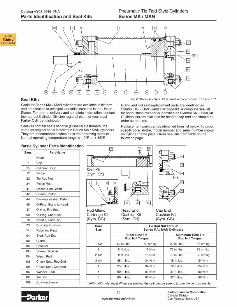
Seal KitsSeals for Series MA / MAN cylinders are available in kit form and are stocked in principal industrial locations in the United States. For prompt delivery and complete information, contact the nearest Cylinder Division regional plant, or your local Parker Cylinder distributor.
Seal kits contain seals of nitrile (Buna-N) elastomers, the same as original seals installed in Series MA / MAN cylinders. They are recommended when air is the operating medium. Normal operating temperature range is -10°F. to +165°F.
* (-0%, +5% tolerance) When assembling the cylinder, be sure to torque the tie rods evenly.
‡on 6" Bore only Sym. 73 is used in place of Sym. 106 and 107.
Seal Kit(Sym. SK)
Rod GlandCartridge Kit(Sym. RG)
Head EndCushion Kit(Sym. CH)
Cap EndCushion Kit(Sym. CC)
22 1 34 15 108 109 17 710210394 69 70 105
101 104 41 45 47 44 42 47
70
69
106
107
73
74
101 104 41 45
47 42 47
69 70 105
74
107
106
69
70
7322 1 34 15 108 109 17 710210394 69 70 105
101 104 41 45 47 44 42 47
70
69
106
107
73
74
101 104 41 45
47 42 47
69 70 105
74
107
106
69
70
73
Parts Identification and Seal Kits
BoreSize
Tie Rod Nut Torque*Series MA / MAN Cylinders
Steel Tube TieRod Nut Torque
Aluminum Tube TieRod Nut Torque
1 1/2 60 in.-lbs. 69 cm-kg 20 in.-lbs. 23 cm-kg
2 11 ft.-lbs. 15 N.m 72 in.-lbs. 83 cm-kg
2 1/2 11 ft.-lbs. 15 N.m 72 in.-lbs. 83 cm-kg
3 1/4 25 ft.-lbs. 34 N.m 18 ft.-lbs. 24 N.m
4 25 ft.-lbs. 34 N.m 18 ft.-lbs. 24 N.m
5 60 ft.-lbs. 81 N.m 37 ft.-lbs. 50 N.m
6 60 ft.-lbs. 81 N.m 37 ft.-lbs. 50 N.m
Sym. Part Name
1 Head
7 Cap
15 Cylinder Body
17 Piston
22 Tie Rod Nut
34 Piston Rod
41 Lipseal Rod Gland
42 Lipseal, Piston
44 Back-up washer, Piston
45 O-Ring, Gland to Head
47 O-ring, End Seal
69 O-Ring, Cush. Adj.
70 Needle, Cush. Adj.
73 Bushing, Cushion
74 Retaining Ring
94 Stud, Rod End
101 Gland
102 Retainer
103 Screw, Retainer
104 Wiper, Rod
105 Check Seal, Rod End
106 Check Seal, Cap End
107 Washer, Seal
108 Tie Rod
109 Cushion Sleeve
Gland and rod seal replacement parts are identified as Symbol RG – Rod Gland Cartridge Kit. A complete seal kit for noncushion cylinder is identified as Symbol SK – Seal Kit. Cushion kits are available for head or cap end and should be order as required.
Replacement parts can be identified from list below. To order specify bore, stroke, model number and serial number shown on cylinder name plate. Order seal kits from table on the following page.
Basic Cylinder Parts Identification

Pneumatic Tie Rod Style CylindersSeries MA / MAN
Parker Hannifin CorporationCylinder DivisionDes Plaines, Illinois USAwww.parker.com/cylinder
Catalog HY08-0915-1/NA
22
Bore Size
Rod Dia.
Rod No.
SKL Seal Kits SK Magnetic Seal Kits
Series MA Series MAN Series MA Series MAN
Consisting of: 1 ea. Symbol # 41, 45, 104,
& 2 ea. Symbol # 42 & 47
Consisting of: 1 ea. Symbol # 41, 45, 104, & 2 ea. Symbol # 42, 47,
129 & 130
Consisting of: 1 ea. Symbol # 41, 43, 45, 104,121 & 2 ea. Symbol # 42, & 47;
plus 1 ea. Quad Seal for old design.
Service Class 1 Only Service Class 1 Only
Part Number Part Number Part Number Part Number
1 1/2" 5/8" 1 SKL7000MA* SKL7000MAN SKM7000MA1 SKM7000MAN
2"5/8" 1 SKL7001MA* SKL7001MAN SKM7001MA1 SKM7001MAN
1" 3 SKL7002MA* SKL7002MAN SKM7002MA1 SKM7002MAN
2 1/2"5/8" 1 SKL7003MA* SKL7003MAN SKM7003MA1 SKM7003MAN
1" 3 SKL7004MA* SKL7004MAN SKM7004MA1 SKM7004MAN
3 1/4"1" 1 SKL7005MA* SKL7005MAN SKM7005MA1 SKM7005MAN
1 3/8" 3 SKL7006MA* SKL7006MAN SKM7006MA1 SKM7006MAN
4"1" 1 SKL7007MA* SKL7007MAN SKM7007MA1 SKM7007MAN
1 3/8" 3 SKL7008MA* SKL7008MAN SKM7008MA1 SKM7008MAN
5"1" 1 SKL7009MA* SKL7009MAN SKM7009MA1 SKM7009MAN
1 3/8" 3 SKL7010MA* SKL7010MAN SKM7010MA1 SKM7010MAN
6" 1 3/8" 1 SKL7098MA* SKL7098MAN SKM7098MA1 SKM7098MAN
Service Kits & Replacement Parts for Series MA / MAN CylindersSeal Kits
Bore Size
Rod Dia.
Rod No.
Rod Gland Cartridge Kits Cushion Kits
Series MA Series MAN Series MA & MAN
Consisting of: 1 each Symbol # 41, 45, 101 &
104
Consisting of: 1 ea. Sym. # 41, 45, 101, 104,
131 & 132
Contains: 1 each Symbol # 69, 70 & 105
Contains: 1 each Symbol # 69, 70, 74,
106 & 107
Service Class 1 Only**
Service Class 1 Only Head End (CH) Cap End (CC) ***
Part Number Part Number Part Number Part Number
1 1/2" 5/8" 1RGL6948MA* L070850040
CHL7011MA1
CCL7016MA12"
5/8" 1 CHL7012MA11" 3 RGL6949MA* L070850100 CHL7013MA1
2 1/2"5/8" 1 RGL6948MA* L070850040 CHL7012MA11" 3 RGL6949MA* L070850100 CHL7013MA1
3 1/4"1" 1
RGL6950MA* L070850124CHL7014MA1
CCL7017MA1
1 3/8" 3 CHL7015MA1
4"1" 1 RGL6949MA* L070850100 CHL7014MA1
1 3/8" 3 RGL6950MA* L070850124 CHL7015MA1
5"1" 1 RGL6949MA* L070850100 CHL7014MA1
1 3/8" 3RGL6950MA* L070850124
CHL7015MA16" 1 3/8" 1 CHL7170MA1 CCL7171MA1
* Ten (10) full digits are required to complete these part numbers. Replace asterisk ( * ) with Service Class #1 or #5 as required for series MA non-magnetic cylinders. Service class 1 only for Series MAN and magnetic piston cylinders.
Rod Gland Seal Kits & Cushion Kits
* Ten (10) full digits are required to complete these part numbers. Replace asterisk ( * ) with Service Class #1 or #5 as required. ** For Class 5 consult factory. *** 6" bore cap end cushion (CC) kit contains 1 each symbol # 69, 70, 73 & 74.
Service Kits & Replacement Parts

Pneumatic Tie Rod Style CylindersSeries MA / MAN
Parker Hannifin CorporationCylinder DivisionDes Plaines, Illinois USAwww.parker.com/cylinder
Catalog HY08-0915-1/NA
23
Manufacturing LocationsRegional Plants
California 221 Helicopter Circle Corona, CA 92880 Tel.: (951) 280-3800 Fax: (951) 280-3808 Fax: (800) 869-9886
Connecticut 80 Shaker Road Enfield, CT 06082 Tel.: (860) 749-2215 Fax: (800) 323-0105
Georgia 1300 Six Flags Road Lithia Springs, GA 30122 Tel.: (770) 819-3400 Fax: (800) 437-3498
Indiana Goodland Plant 715 South Iroquois Street Goodland, IN 47948 Tel.: (219) 297-3182 Fax: (800) 328-8120
Michigan 900 Plymouth Road Plymouth, MI 48170 Tel.: (734) 455-1700 Fax: (734) 455-1007
Oregon 29289 Airport Road Eugene, OR 97402-0079 Tel.: (541) 689-9111 Fax: (541) 688-6771 Fax: (800) 624-7996
Manufacturing Locations

Pneumatic Tie Rod Style CylindersSeries MA / MAN
Parker Hannifin CorporationCylinder DivisionDes Plaines, Illinois USAwww.parker.com/cylinder
Catalog HY08-0915-1/NA
24
Cylinder Safety Guide
Before selecting or using Parker Hannifin Corporation (the Company) cylinders or related accessories, it is important that you read, understand and follow the following safety information. Training is advised before selecting and using the Company’s products.
1.0 General Instructions 1.1 Scope – This safety guide provides instructions for selecting and using
(including assembling, installing, and maintaining) cylinder products. This safety guide is a supplement to and is to be used with the specific Company publications for the specific cylinder products that are being considered for use.
1.2 Fail Safe – Cylinder products can and do fail without warning for many reasons. All systems and equipment should be designed in a fail-safe mode so that if the failure of a cylinder product occurs people and property won’t be endangered.
1.3 Distribution – Provide a free copy of this safety guide to each person responsible for selecting or using cylinder products. Do not select or use the Company’s cylinders without thoroughly reading and understanding this safety guide as well as the specific Company publications for the products considered or selected.
1.4 User Responsibility – Due to very wide variety of cylinder applications and cylinder operating conditions, the Company does not warrant that any particular cylinder is suitable for any specific application. This safety guide does not analyze all technical parameters that must be considered in select-ing a product. The hydraulic and pneumatic cylinders outlined in this catalog are designed to the Company’s design guidelines and do not necessarily meet the design guideline of other agencies such as American Bureau of Shipping, ASME Pressure Vessel Code etc. The user, through its own analysis and testing, is solely responsible for:
• Making the final selection of the cylinders and related accessories. • Determining if the cylinders are required to meet specific design require-
ments as required by the Agency(s) or industry standards covering the design of the user’s equipment.
• Assuring that the user’s requirements are met, OSHA requirements are met, and safety guidelines from the applicable agencies such as but not limited to ANSI are followed and that the use presents no health or safety hazards.
• Providing all appropriate health and safety warnings on the equipment on which the cylinders are used.
1.5 Additional Questions – Call the appropriate Company technical service department if you have any questions or require any additional information. See the Company publication for the product being considered or used, or call 1-847-298-2400, or go to www.parker.com, for telephone numbers of the appropriate technical service department.
2.0 Cylinder and Accessories Selection 2.1 Seals – Part of the process of selecting a cylinder is the selection of
seal compounds. Before making this selection, consult the “seal information page(s)” of the publication for the series of cylinders of interest.
The application of cylinders may allow fluids such as cutting fluids, wash down fluids etc. to come in contact with the external area of the cylinder. These fluids may attack the piston rod wiper and or the primary seal and must be taken into account when selecting and specifying seal compounds.
Dynamic seals will wear. The rate of wear will depend on many operating factors. Wear can be rapid if a cylinder is mis-aligned or if the cylinder has been improperly serviced. The user must take seal wear into consideration in the application of cylinders.
2.2 Piston Rods – Possible consequences of piston rod failure or separation of the piston rod from the piston include, but are not limited to are:
• Piston rod and or attached load thrown off at high speed. • High velocity fluid discharge. • Piston rod extending when pressure is applied in the piston
retract mode.
Piston rods or machine members attached to the piston rod may move suddenly and without warning as a consequence of other conditions occurring to the machine such as, but not limited to:
• Unexpected detachment of the machine member from the piston rod.
• Failure of the pressurized fluid delivery system (hoses, fittings, valves, pumps, compressors) which maintain cylinder position.
• Catastrophic cylinder seal failure leading to sudden loss of pressurized fluid.
• Failure of the machine control system. Follow the recommendations of the “Piston Rod Selection Chart and Data”
in the publication for the series of cylinders of interest. The suggested piston rod diameter in these charts must be followed in order to avoid piston rod buckling.
Piston rods are not normally designed to absorb bending moments or loads which are perpendicular to the axis of piston rod motion. These additional loads can cause the piston rod to fail. If these types of additional loads are expected to be imposed on the piston rod, their magnitude should be made known to our engineering department.
The cylinder user should always make sure that the piston rod is securely attached to the machine member.
On occasion cylinders are ordered with double rods (a piston rod extended from both ends of the cylinder). In some cases a stop is threaded on to one of the piston rods and used as an external stroke adjuster. On occasions spacers are attached to the machine member connected to the piston rod and also used as a stroke adjuster. In both cases the stops will create a pinch point and the user should consider appropriate use of guards. If these external stops are not perpendicular to the mating contact surface, or if debris is trapped between the contact surfaces, a bending moment will be placed on the piston rod, which can lead to piston rod failure. An external stop will also negate the effect of cushioning and will subject the piston rod to impact loading. Those two (2) conditions can cause piston rod failure. Internal stroke adjusters are available with and without cushions. The use of external stroke adjusters should be reviewed with our engineering department.
The piston rod to piston and the stud to piston rod threaded connections are secured with an anaerobic adhesive. The strength of the adhesive decreases with increasing temperature. Cylinders which can be exposed to tempera-tures above +250°F (+121°C) are to be ordered with a non studded piston rod and a pinned piston to rod joint.
2.3 Cushions – Cushions should be considered for cylinder applications when the piston velocity is expected to be over 4 inches/second.
Cylinder cushions are normally designed to absorb the energy of a linear applied load. A rotating mass has considerably more energy than the same mass moving in a linear mode. Cushioning for a rotating mass application should be reviewed by our engineering department.
2.4 Cylinder Mountings – Some cylinder mounting configurations may have certain limitations such as but not limited to minimum stroke for side or foot mounting cylinders or pressure de-ratings for certain mounts. Carefully review the catalog for these types of restrictions.
Always mount cylinders using the largest possible high tensile alloy steel socket head cap screws that can fit in the cylinder mounting holes and torque them to the manufacturer’s recommendations for their size.
2.5 Port Fittings – Hydraulic cylinders applied with meter out or decelera-tion circuits are subject to intensified pressure at piston rod end.
The rod end pressure is approximately equal to:
operating pressure x effective cap end area effective rod end piston area
Contact your connector supplier for the pressure rating of individual connectors.
3.0 Cylinder and Accessories Installation and Mounting 3.1 Installation 3.1.1 – Cleanliness is an important consideration, and cylinders are
shipped with the ports plugged to protect them from contaminants enter-ing the ports. These plugs should not be removed until the piping is to be installed. Before making the connection to the cylinder ports, piping should be thoroughly cleaned to remove all chips or burrs which might have resulted from threading or flaring operations.
Safety Guide for Selecting and Using Hydraulic, Pneumatic Cylinders and Their Accessories
WARNING: FAILURE OF THE CYLINDER, ITS PARTS, ITS MOUNTING, ITS CONNECTIONS TO OTHER OBJECTS, OR ITS CONTROLS CAN RESULT IN: • Unanticipated or uncontrolled movement of the cylinder or objects connected to it. • Falling of the cylinder or objects held up by it. • Fluid escaping from the cylinder, potentially at high velocity.THESE EVENTS COULD CAUSE DEATH OR PERSONAL INJURY BY, FOR EXAMPLE, PERSONS FALLING FROM HIGH LOCATIONS, BEING CRUSHED OR STRUCK BY HEAVY OR FAST MOVING OBJECTS, BEING PUSHED INTO DANGEROUS EQUIPMENT OR SITUATIONS, OR SLIPPING ON ESCAPED FLUID.

Pneumatic Tie Rod Style CylindersSeries MA / MAN
Parker Hannifin CorporationCylinder DivisionDes Plaines, Illinois USAwww.parker.com/cylinder
Catalog HY08-0915-1/NA
25
3.1.2 – Cylinders operating in an environment where air drying materials are present such as fast-drying chemicals, paint, or weld splatter, or other hazardous conditions such as excessive heat, should have shields installed to prevent damage to the piston rod and piston rod seals.
3.1.3 – Proper alignment of the cylinder piston rod and its mating component on the machine should be checked in both the extended and retracted positions. Improper alignment will result in excessive rod gland and/or cylinder bore wear. On fixed mounting cylinders attaching the pis-ton rod while the rod is retracted will help in achieving proper alignment.
3.1.4 – Sometimes it may be necessary to rotate the piston rod in order to thread the piston rod into the machine member. This operation must always be done with zero pressure being applied to either side of the piston. Failure to follow this procedure may result in loosening the piston to rod-threaded connection. In some rare cases the turning of the piston rod may rotate a threaded piston rod gland and loosen it from the cylinder head. Confirm that this condition is not occurring. If it does, re-tighten the piston rod gland firmly against the cylinder head.
For double rod cylinders it is also important that when attaching or detaching the piston rod from the machine member that the torque be applied to the piston rod end of the cylinder that is directly attaching to the machine member with the opposite end unrestrained. If the design of the machine is such that only the rod end of the cylinder opposite to where the rod attaches to the machine member can be rotated, consult the factory for further instructions.
3.2 Mounting Recommendations 3.2.1 – Always mount cylinders using the largest possible high tensile
alloy steel socket head screws that can fit in the cylinder mounting holes and torque them to the manufacturer’s recommendations for their size.
3.2.2 – Side-Mounted Cylinders – In addition to the mounting bolts, cylinders of this type should be equipped with thrust keys or dowel pins located so as to resist the major load.
3.2.3 – Tie Rod Mounting – Cylinders with tie rod mountings are recom-mended for applications where mounting space is limited. The standard tie rod extension is shown as BB in dimension tables. Longer or shorter extensions can be supplied. Nuts used for this mounting style should be torqued to the same value as the tie rods for that bore size.
3.2.4 – Flange Mount Cylinders – The controlled diameter of the rod gland extension on head end flange mount cylinders can be used as a pilot to locate the cylinders in relation to the machine. After align-ment has been obtained, the flanges may be drilled for pins or dowels to prevent shifting.
3.2.5 – Trunnion Mountings – Cylinders require lubricated bearing blocks with minimum bearing clearances. Bearing blocks should be carefully aligned and rigidly mounted so the trunnions will not be subjected to bending moments. The rod end should also be pivoted with the pivot pin in line and parallel to axis of the trunnion pins.
3.2.6 – Clevis Mountings – Cylinders should be pivoted at both ends with centerline of pins parallel to each other. After cylinder is mounted, be sure to check to assure that the cylinder is free to swing through its working arc without interference from other machine parts.
4.0 Cylinder and Accessories Maintenance, Troubleshooting and Replacement
4.1 Storage – At times cylinders are delivered before a customer is ready to install them and must be stored for a period of time. When storage is required the following procedures are recommended.
4.1.1 – Store the cylinders in an indoor area which has a dry, clean and noncorrosive atmosphere. Take care to protect the cylinder from both internal corrosion and external damage.
4.1.2 – Whenever possible cylinders should be stored in a vertical posi-tion (piston rod up). This will minimize corrosion due to possible conden-sation which could occur inside the cylinder. This will also minimize seal damage.
4.1.3 – Port protector plugs should be left in the cylinder until the time of installation.
4.1.4 – If a cylinder is stored full of hydraulic fluid, expansion of the fluid due to temperature changes must be considered. Installing a check valve with free flow out of the cylinder is one method.
4.1.5 – When cylinders are mounted on equipment that is stored outside for extended periods, exposed unpainted surfaces, e.g. piston rod, must be coated with a rust-inhibiting compound to prevent corrosion.
4.2 Cylinder Trouble Shooting
4.2.1 – External Leakage 4.2.1.1 – Rod seal leakage can generally be traced to worn or
damaged seals. Examine the piston rod for dents, gouges or score marks, and replace piston rod if surface is rough.
Rod seal leakage could also be traced to gland wear. If clearance is excessive, replace rod bushing and seal. Rod seal leakage can also be traced to seal deterioration. If seals are soft or gummy or brittle, check compatibility of seal material with lubricant used if air cylinder, or operating fluid if hydraulic cylinder. Replace with seal material, which is compatible with these fluids. If the seals are hard or have lost elasticity, it is usually due to exposure to temperatures in excess of 165°F. (+74°C). Shield the cylinder from the heat source to limit temperature to 350°F. (+177°C.) and replace with fluorocarbon seals.
4.2.1.2 – Cylinder body seal leak can generally be traced to loose tie rods. Torque the tie rods to manufacturer’s recommendation for that bore size.
Excessive pressure can also result in cylinder body seal leak. Determine maximum pressure to rated limits. Replace seals and retorque tie rods as in paragraph above. Excessive pressure can also result in cylinder body seal leak. Determine if the pressure rating of the cylinder has been exceeded. If so, bring the operating pressure down to the rating of the cylinder and have the tie rods replaced.
Pinched or extruded cylinder body seal will also result in a leak. Replace cylinder body seal and retorque as in paragraph above.
Cylinder body seal leakage due to loss of radial squeeze which shows up in the form of flat spots or due to wear on the O.D. or I.D. – Either of these are symptoms of normal wear due to high cycle rate or length of service. Replace seals as per paragraph above.
4.2.2 – Internal Leakage 4.2.2.1 – Piston seal leak (by-pass) 1 to 3 cubic inches per minute
leakage is considered normal for piston ring construction. Virtually no static leak with lipseal type seals on piston should be expected. Piston seal wear is a usual cause of piston seal leakage. Replace seals as required.
4.2.2.2 – With lipseal type piston seals excessive back pressure due to over-adjustment of speed control valves could be a direct cause of rapid seal wear. Contamination in a hydraulic system can result in a scored cylinder bore, resulting in rapid seal wear. In either case, replace piston seals as required.
4.2.2.3 – What appears to be piston seal leak, evidenced by the fact that the cylinder drifts, is not always traceable to the piston. To make sure, it is suggested that one side of the cylinder piston be pressurized and the fluid line at the opposite port be disconnected. Observe leakage. If none is evident, seek the cause of cylinder drift in other component parts in the circuit.
4.2.3 – Cylinder Fails to Move the Load 4.2.3.1 – Pneumatic or hydraulic pressure is too low. Check the
pressure at the cylinder to make sure it is to circuit requirements. 4.2.3.2 – Piston Seal Leak – Operate the valve to cycle the cylinder
and observe fluid flow at valve exhaust ports at end of cylinder stroke. Replace piston seals if flow is excessive.
4.2.3.3 – Cylinder is undersized for the load – Replace cylinder with one of a larger bore size.
4.3 Erratic or Chatter Operation 4.3.1 – Excessive friction at rod gland or piston bearing due to load
misalignment – Correct cylinder-to-load alignment. 4.3.2 – Cylinder sized too close to load requirements – Reduce load or
install larger cylinder. 4.3.3 – Erratic operation could be traced to the difference between
static and kinetic friction. Install speed control valves to provide a back pressure to control the stroke.
4.4 Cylinder Modifications, Repairs, or Failed Component – Cylinders as shipped from the factory are not to be disassembled and or modified. If cylinders require modifications, these modifications must be done at company locations or by the Company’s certified facilities. The Cylinder Division Engineering Department must be notified in the event of a mechanical fracture or permanent deformation of any cylinder component (excluding seals). This includes a broken piston rod, tie rod, mounting accessory or any other cylinder component. The notification should include all operation and application details. This information will be used to provide an engineered repair that will prevent recurrence of the failure.
It is allowed to disassemble cylinders for the purpose of replacing seals or seal assemblies. However, this work must be done by strictly following all the instructions provided with the seal kits.
Cylinder Safety Guide

Pneumatic Tie Rod Style CylindersSeries MA / MAN
Parker Hannifin CorporationCylinder DivisionDes Plaines, Illinois USAwww.parker.com/cylinder
Catalog HY08-0915-1/NA
26
Offer of Sale
The items described in this document and other documents and descriptions provided by Parker Hannifin Corporation, its subsidiaries and its authorized distributors (“Seller”) are hereby offered for sale at prices to be established by Seller. This offer and its acceptance by any customer (“Buyer”) shall be governed by all of the following Terms and Conditions. Buyer’s order for any item described in its document, when communicated to Seller verbally, or in writing, shall constitute acceptance of this offer. All goods, services or work described will be referred to as “Products”.
1. Terms and Conditions. Seller’s willingness to offer Products, or accept an order for Products, to or from Buyer is subject to these Terms and Conditions or any newer version of the terms and conditions found on-line at www.parker.com/saleterms/. Seller objects to any contrary or additional terms or conditions of Buyer’s order or any other document issued by Buyer.2. Price Adjustments; Payments. Prices stated on Seller’s quote or other documen-tation offered by Seller are valid for 30 days, and do not include any sales, use, or other taxes unless specifically stated. Unless otherwise specified by Seller, all prices are F.C.A. Seller’s facility (INCOTERMS 2010). Payment is subject to credit approval and is due 30 days from the date of invoice or such other term as required by Seller’s Credit Department, after which Buyer shall pay interest on any unpaid invoices at the rate of 1.5% per month or the maximum allowable rate under applicable law.3. Delivery Dates; Title and Risk; Shipment. All delivery dates are approximate and Seller shall not be responsible for any damages resulting from any delay. Regardless of the manner of shipment, title to any products and risk of loss or damage shall pass to Buyer upon placement of the products with the shipment carrier at Seller’s facility. Unless otherwise stated, Seller may exercise its judgment in choosing the carrier and means of delivery. No deferment of shipment at Buyers’ request beyond the respec-tive dates indicated will be made except on terms that will indemnify, defend and hold Seller harmless against all loss and additional expense. Buyer shall be responsible for any additional shipping charges incurred by Seller due to Buyer’s acts or omissions.4. Warranty. Seller warrants that the Products sold hereunder shall be free from defects in material or workmanship for a period of eighteen months from the date of delivery to Buyer. The prices charged for Seller’s products are based upon the exclu-sive limited warranty stated above, and upon the following disclaimer: DISCLAIMER OF WARRANTY: THIS WARRANTY COMPRISES THE SOLE AND ENTIRE WARRANTY PERTAINING TO PRODUCTS PROVIDED HEREUNDER. SELLER DISCLAIMS ALL OTHER WARRANTIES, EXPRESS AND IMPLIED, INCLUDING DESIGN, MERCHANTABILITY AND FITNESS FOR A PARTICULAR PURPOSE.5. Claims; Commencement of Actions. Buyer shall promptly inspect all Products upon delivery. No claims for shortages will be allowed unless reported to the Seller within 10 days of delivery. No other claims against Seller will be allowed unless asserted in writing within 30 days after delivery. Buyer shall notify Seller of any alleged breach of warranty within 30 days after the date the defect is or should have been discovered by Buyer. Any action based upon breach of this agreement or upon any other claim arising out of this sale (other than an action by Seller for an amount due on any invoice) must be commenced within 12 months from the date of the breach without regard to the date breach is discovered.6. LIMITATION OF LIABILITY. UPON NOTIFICATION, SELLER WILL, AT ITS OPTION, REPAIR OR REPLACE A DEFECTIVE PRODUCT, OR REFUND THE PURCHASE PRICE. IN NO EVENT SHALL SELLER BE LIABLE TO BUYER FOR ANY SPECIAL, INDIRECT, INCIDENTAL OR CONSEQUENTIAL DAMAGES ARISING OUT OF, OR AS THE RESULT OF, THE SALE, DELIVERY, NON-DELIVERY, SERVICING, USE OR LOSS OF USE OF THE PRODUCTS OR ANY PART THEREOF, OR FOR ANY CHARGES OR EXPENSES OF ANY NATURE INCURRED WITHOUT SELLER’S WRITTEN CONSENT, EVEN IF SELLER HAS BEEN NEGLIGENT, WHETHER IN CONTRACT, TORT OR OTHER LEGAL THEORY. IN NO EVENT SHALL SELLER’S LIABILITY UNDER ANY CLAIM MADE BY BUYER EXCEED THE PURCHASE PRICE OF THE PRODUCTS.7. User Responsibility. The user, through its own analysis and testing, is solely responsible for making the final selection of the system and Product and assuring that all performance, endurance, maintenance, safety and warning requirements of the application are met. The user must analyze all aspects of the application and follow applicable industry standards and Product information. If Seller provides Product or system options, the user is responsible for determining that such data and specifica-tions are suitable and sufficient for all applications and reasonably foreseeable uses of the Products or systems.8. Loss to Buyer’s Property. Any designs, tools, patterns, materials, drawings, confi-dential information or equipment furnished by Buyer or any other items which become Buyer’s property, will be considered obsolete and may be destroyed by Seller after two consecutive years have elapsed without Buyer ordering the items manufactured using such property. Seller shall not be responsible for any loss or damage to such property while it is in Seller’s possession or control.9. Special Tooling. A tooling charge may be imposed for any special tooling, includ-ing without limitation, dies, fixtures, molds and patterns, acquired to manufacture Products. Such special tooling shall be and remain Seller’s property notwithstanding payment of any charges by Buyer. In no event will Buyer acquire any interest in appa-ratus belonging to Seller which is utilized in the manufacture of the Products, even if such apparatus has been specially converted or adapted for such manufacture and notwithstanding any charges paid by Buyer. Unless otherwise agreed, Seller shall have the right to alter, discard or otherwise dispose of any special tooling or other property in its sole discretion at any time.10. Buyer’s Obligation; Rights of Seller. To secure payment of all sums due or oth-erwise, Seller shall retain a security interest in the goods delivered and this agreement shall be deemed a Security Agreement under the Uniform Commercial Code. Buyer authorizes Seller as its attorney to execute and file on Buyer’s behalf all documents Seller deems necessary to perfect its security interest. 11. Improper use and Indemnity. Buyer shall indemnify, defend, and hold Seller harmless from any claim, liability, damages, lawsuits, and costs (including attorney fees), whether for personal injury, property damage, patent, trademark or copyright
infringement or any other claim, brought by or incurred by Buyer, Buyer’s employees, or any other person, arising out of: (a) improper selection, improper application or other misuse of Products purchased by Buyer from Seller; (b) any act or omission, negligent or otherwise, of Buyer; (c) Seller’s use of patterns, plans, drawings, or specifications furnished by Buyer to manufacture Product; or (d) Buyer’s failure to comply with these terms and conditions. Seller shall not indemnify Buyer under any circumstance except as otherwise provided.12. Cancellations and Changes. Orders shall not be subject to cancellation or change by Buyer for any reason, except with Seller’s written consent and upon terms that will indemnify, defend and hold Seller harmless against all direct, incidental and consequential loss or damage. Seller may change product features, specifications, designs and availability with notice to Buyer.13. Limitation on Assignment. Buyer may not assign its rights or obligations under this agreement without the prior written consent of Seller.14. Force Majeure. Seller does not assume the risk and shall not be liable for delay or failure to perform any of Seller’s obligations by reason of circumstances beyond the reasonable control of Seller (hereinafter “Events of Force Majeure”). Events of Force Majeure shall include without limitation: accidents, strikes or labor disputes, acts of any government or government agency, acts of nature, delays or failures in delivery from carriers or suppliers, shortages of materials, or any other cause beyond Seller’s reasonable control. 15. Waiver and Severability. Failure to enforce any provision of this agreement will not waive that provision nor will any such failure prejudice Seller’s right to enforce that provision in the future. Invalidation of any provision of this agreement by legislation or other rule of law shall not invalidate any other provision herein. The remaining provi-sions of this agreement will remain in full force and effect.16. Termination. Seller may terminate this agreement for any reason and at any time by giving Buyer thirty (30) days written notice of termination. Seller may immediately terminate this agreement, in writing, if Buyer: (a) commits a breach of any provision of this agreement (b) appointments a trustee, receiver or custodian for all or any part of Buyer’s property (c) files a petition for relief in bankruptcy on its own behalf, or by a third party (d) makes an assignment for the benefit of creditors, or (e) dissolves or liquidates all or a majority of its assets.17. Governing Law. This agreement and the sale and delivery of all Products here-under shall be deemed to have taken place in and shall be governed and construed in accordance with the laws of the State of Ohio, as applicable to contracts executed and wholly performed therein and without regard to conflicts of laws principles. Buyer irrevocably agrees and consents to the exclusive jurisdiction and venue of the courts of Cuyahoga County, Ohio with respect to any dispute, controversy or claim arising out of or relating to this agreement. 18. Indemnity for Infringement of Intellectual Property Rights. Seller shall have no liability for infringement of any patents, trademarks, copyrights, trade dress, trade secrets or similar rights except as provided in this Section. Seller will defend and indemnify Buyer against allegations of infringement of U.S. patents, U.S. trademarks, copyrights, trade dress and trade secrets (“Intellectual Property Rights”). Seller will defend at its expense and will pay the cost of any settlement or damages awarded in an action brought against Buyer based on an allegation that a Product sold pursuant to this Agreement infringes the Intellectual Property Rights of a third party. Seller’s obliga-tion to defend and indemnify Buyer is contingent on Buyer notifying Seller within ten (10) days after Buyer becomes aware of such allegations of infringement, and Seller having sole control over the defense of any allegations or actions including all negotia-tions for settlement or compromise. If a Product is subject to a claim that it infringes the Intellectual Property Rights of a third party, Seller may, at its sole expense and option, procure for Buyer the right to continue using the Product, replace or modify the Product so as to make it noninfringing, or offer to accept return of the Product and return the purchase price less a reasonable allowance for depreciation. Notwithstanding the fore-going, Seller shall have no liability for claims of infringement based on information provided by Buyer, or directed to Products delivered hereunder for which the designs are specified in whole or part by Buyer, or infringements resulting from the modification, combination or use in a system of any Product sold hereunder. The foregoing provi-sions of this Section shall constitute Seller’s sole and exclusive liability and Buyer’s sole and exclusive remedy for infringement of Intellectual Property Rights.19. Entire Agreement. This agreement contains the entire agreement between the Buyer and Seller and constitutes the final, complete and exclusive expression of the terms of sale. All prior or contemporaneous written or oral agreements or negotiations with respect to the subject matter are herein merged.20. Compliance with Law, U. K. Bribery Act and U.S. Foreign Corrupt Practices Act. Buyer agrees to comply with all applicable laws and regulations, including both those of the United Kingdom and the United States of America, and of the country or countries of the Territory in which Buyer may operate, including without limitation the U. K. Bribery Act, the U.S. Foreign Corrupt Practices Act (“FCPA”) and the U.S. Anti-Kickback Act (the “Anti-Kickback Act”), and agrees to indemnify and hold harmless Seller from the consequences of any violation of such provisions by Buyer, its employ-ees or agents. Buyer acknowledges that they are familiar with the provisions of the U. K. Bribery Act, the FCPA and the Anti-Kickback Act, and certifies that Buyer will adhere to the requirements thereof. In particular, Buyer represents and agrees that Buyer shall not make any payment or give anything of value, directly or indirectly to any governmental official, any foreign political party or official thereof, any candidate for foreign political office, or any commercial entity or person, for the purpose of influ-encing such person to purchase products or otherwise benefit the business of Seller.
Offer of Sale
AerospaceKey MarketsAftermarket services Commercial transportsEnginesGeneral & business aviationHelicoptersLaunch vehiclesMilitary aircraftMissilesPower generation Regional transportsUnmanned aerial vehicles
Key ProductsControl systems & actuation productsEngine systems & componentsFluid conveyance systems& componentsFluid metering, delivery & atomization devicesFuel systems & componentsFuel tank inerting systemsHydraulic systems & componentsThermal managementWheels & brakes
ElectromechanicalKey MarketsAerospaceFactory automationLife science & medicalMachine toolsPackaging machineryPaper machineryPlastics machinery & convertingPrimary metalsSemiconductor & electronicsTextileWire & cable
Key ProductsAC/DC drives & systemsElectric actuators, gantry robots & slidesElectrohydrostatic actuation systemsElectromechanical actuation systemsHuman machine interfaceLinear motorsStepper motors, servo motors, drives & controlsStructural extrusions
PneumaticsKey MarketsAerospaceConveyor & material handlingFactory automationLife science & medicalMachine toolsPackaging machineryTransportation & automotive
Key ProductsAir preparationBrass fittings & valvesManifoldsPneumatic accessoriesPneumatic actuators & grippersPneumatic valves & controlsQuick disconnectsRotary actuatorsRubber & thermoplastic hose & couplingsStructural extrusionsThermoplastic tubing & fittingsVacuum generators, cups & sensors
Fluid & Gas HandlingKey Markets Aerial liftAgricultureBulk chemical handlingConstruction machineryFood & beverageFuel & gas deliveryIndustrial machineryLife sciences MarineMiningMobileOil & gasRenewable energyTransportation
Key Products Check valves Connectors for low pressure fluid conveyanceDeep sea umbilicalsDiagnostic equipment Hose couplingsIndustrial hoseMooring systems & power cablesPTFE hose & tubing Quick couplingsRubber & thermoplastic hose Tube fittings & adaptersTubing & plastic fittings
HydraulicsKey Markets Aerial liftAgricultureAlternative energyConstruction machineryForestryIndustrial machineryMachine toolsMarineMaterial handlingMiningOil & gasPower generationRefuse vehiclesRenewable energyTruck hydraulicsTurf equipment
Key Products AccumulatorsCartridge valvesElectrohydraulic actuatorsHuman machine interfacesHybrid drivesHydraulic cylinders Hydraulic motors & pumpsHydraulic systemsHydraulic valves & controlsHydrostatic steeringIntegrated hydraulic circuitsPower take-offs Power unitsRotary actuatorsSensors
Process ControlKey Markets Alternative fuelsBiopharmaceuticalsChemical & refiningFood & beverageMarine & shipbuildingMedical & dentalMicroelectronicsNuclear PowerOffshore oil explorationOil & gasPharmaceuticalsPower generationPulp & paperSteelWater/wastewater
Key ProductsAnalytical Instruments Analytical sample conditioningproducts & systemsChemical injection fittings& valvesFluoropolymer chemicaldelivery fittings, valves & pumpsHigh purity gas delivery fittings, valves, regulators& digital flow controllersIndustrial mass flow meters/controllersPermanent no-weld tube fittingsPrecision industrial regulators& flow controllersProcess control double block & bleedsProcess control fittings, valves, regulators & manifold valves
Sealing & ShieldingKey Markets AerospaceChemical processingConsumerFluid powerGeneral industrialInformation technologyLife sciencesMicroelectronicsMilitaryOil & gasPower generationRenewable energyTelecommunicationsTransportation
Key Products Dynamic sealsElastomeric o-ringsElectro-medical instrumentdesign & assemblyEMI shieldingExtruded & precision-cut,fabricated elastomeric sealsHigh temperature metal sealsHomogeneous & insertedelastomeric shapesMedical device fabrication & assemblyMetal & plastic retainedcomposite sealsShielded optical windowsSilicone tubing & extrusionsThermal managementVibration dampening
Parker’s Motion & Control Technologies
At Parker, we’re guided by
a relentless drive to help
our customers become more
productive and achieve
higher levels of profitabil-
ity by engineering the best
systems for their require-
ments. It means looking at
customer applications from
many angles to find new
ways to create value. What-
ever the motion and control
technology need, Parker has
the experience, breadth of
product and global reach
to consistently deliver. No
company knows more about
motion and control technol-
ogy than Parker. For further
info call 1 800 C-Parker
(1 800 272 7537)
Climate ControlKey Markets AgricultureAir conditioningConstruction MachineryFood & beverageIndustrial machineryLife sciencesOil & gasPrecision coolingProcessRefrigerationTransportation
Key Products AccumulatorsAdvanced actuatorsCO
2 controls
Electronic controllersFilter driersHand shut-off valvesHeat exchangers Hose & fittingsPressure regulating valvesRefrigerant distributorsSafety relief valvesSmart pumpsSolenoid valvesThermostatic expansion valves
FiltrationKey MarketsAerospaceFood & beverageIndustrial plant & equipmentLife sciencesMarineMobile equipmentOil & gasPower generation & renewable energyProcessTransportation Water Purification
Key Products Analytical gas generatorsCompressed air filters & dryersEngine air, coolant, fuel & oil filtration systemsFluid condition monitoring systemsHydraulic & lubrication filtersHydrogen, nitrogen & zero air generatorsInstrumentation filtersMembrane & fiber filtersMicrofiltrationSterile air filtrationWater desalination & purification filters & systems

11/15 / Catalog HY08-0915-1/NA
Parker Hannifin CorporationCylinder Division500 South Wolf RoadDes Plaines, IL 60016 USAphone (847) 298-2400fax (800) 892-1008www.parker.com/cylinder
Parker Hannifin Corporation Motion and Control Division160 Chisholm Drive Milton, ON Canada L9T 3G9 direct (905) 693-3000 fax (905) 876-1958 www.parker.com