pneumatic cylindertossballslides.com/newpdf_2011/1511-pa-typ-d-en_ab.pdf · phone: 610-759-8883 |...
TRANSCRIPT
Pneumatic cylinder
© 2011 Toss Pneumatics | 539 South Main Street | Nazareth, PA 18064 USA
Phone: 610-759-8883 | Fax: 610-759-1766
Email us at: [email protected] Website: www.tossballslides.com
1
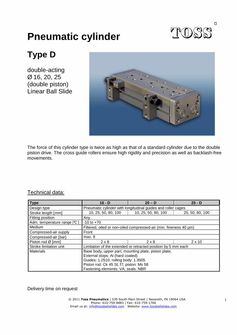
Type D double-acting Ø 16, 20, 25 (double piston) Linear Ball Slide The force of this cylinder type is twice as high as that of a standard cylinder due to the double piston drive. The cross guide rollers ensure high rigidity and precision as well as backlash-free movements.
Technical data:
Type 16 - D 20 – D 25 - D Design type Pneumatic cylinder with longitudinal guides and roller cages Stroke length [mm] 10, 25, 50, 80, 100 10, 25, 50, 80, 100 25, 50, 80, 100 Fitting position Any Adm. temperature range [°C ] -10 to +70 Medium Filtered, oiled or non-oiled compressed-air (min. fineness 40 µm) Compressed-air supply Front Compressed-air [bar] max. 8 Piston rod Ø [mm] 2 x 8 2 x 8 2 x 10 Stroke limitation unit Limitation of the extended or retracted position by 5 mm each Materials Base body, upper part, mounting plate, piston plate,
External stops: Al (hard coated) Guides: 1.2510, rolling body: 1.3505 Piston rod: Ck 45 SL f7; piston: Ms 58 Fastening elements: VA; seals: NBR
Delivery time on request
Pneumatic cylinder
© 2011 Toss Pneumatics | 539 South Main Street | Nazareth, PA 18064 USA
Phone: 610-759-8883 | Fax: 610-759-1766
Email us at: [email protected] Website: www.tossballslides.com
2
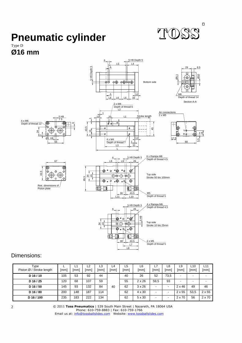
Type D Ø16 mm
L743.5
L1043.5
1
L4
43.5
67
34
30
10
34 10
6
L1130
L96
L9
Ø5 H9
247
55
5 H9
L6L6L6
12
71543
.5
1
LL3
2 x M4
110 L1
8
L2
A
A
L5
5 H
9
26
6 x Rampa M6
26
8.5
33
31
12
45
12
29
M6
Ø5.
1
Ø10
17.568 5.
516
V
R
85.5
L8
6
6
Bottom side
5 H9 Depth 5
5 H
9 D
epth
5
Depth of thread 14
Section A-A
Depth of thread 6
Stroke length
Air connections2 x M5
Depth of thread 4,5
4 x M4Depth of thread 7
5 H9 Depth 5
Top sideStroke 50 bis 100mm
M5Depth of thread 5
4 x Rampa M6Depth of thread 4,5
Top sideStroke 10 bis 25mm
2 x M5Depth of thread 5
5 H9 Depth 5
T 54 x M6Depth of thread 12
Retr. dimensions ofPiston plate
Dimensions:
Type Piston Ø / Stroke length
L L1 L2 L3 L4 L5 L6 L7 L8 L9 L10 L11 [mm] [mm] [mm] [mm] [mm] [mm] [mm] [mm] [mm] [mm] [mm] [mm]
D 16 / 10 105 53 92 44
40
40 26 52 73,5 - - -
D 16 / 25 120 68 107 59 55 2 x 26 59,5 93 - - -
D 16 / 50 145 93 132 84 62 3 x 26 - - 2 x 46 49 46
D 16 / 80 200 148 187 114 62 4 x 30 - - 2 x 55 53,5 2 x 55
D 16 / 100 235 183 222 134 62 5 x 30 - - 2 x 70 56 2 x 70
Pneumatic cylinder
© 2011 Toss Pneumatics | 539 South Main Street | Nazareth, PA 18064 USA
Phone: 610-759-8883 | Fax: 610-759-1766
Email us at: [email protected] Website: www.tossballslides.com
3
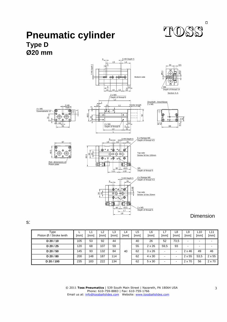
Type D Ø20 mm
L743.5
L1043.5
1
L4
48. 5
67
34
30
1 0
34 10
6
L1130
L96
L9
Tiefe 54 x M6Gewindetiefe 12
Ø5 H9
317
55
5 H9
L6L6L6
12
72048
.5
1
LL3
2 x M4
110 L1
8
L2
A
A
L5
5 H
9
26
6 x Rampa M6
26
8.5
33
Druckluft - Anschlüsse2 x M5
31
12
50
12
34
M6
Ø5.
1
Ø10
17.568 6.
519
V
R
85.5
L8
6
6Bottom side
5 H9 Depth 5
5 H
9 D
epth
5Depth of thread 14
Section A-A
Stroke length
Depth of thread 6
4 x M4Depth of thread 6
Retr. dimensions ofPiston plate
Depth of thread 4,5
Top sideStroke 50 bis 100mm
M5Depth of thread 5
5 H9 Depth 5
5 H9 Depth 5 4 x Rampa M6Depth of thread 4,5
Top sideStroke 10 bis 25mm
2 x M5Depth of thread 5
Dimensions:
Type Piston Ø / Stroke lenth
L L1 L2 L3 L4 L5 L6 L7 L8 L9 L10 L11 [mm] [mm] [mm] [mm] [mm] [mm] [mm] [mm] [mm] [mm] [mm] [mm]
D 20 / 10 105 53 92 44
40
40 26 52 73,5 - - -
D 20 / 25 120 68 107 59 55 2 x 26 59,5 93 - - -
D 20 / 50 145 93 132 84 62 3 x 26 - - 2 x 46 49 46
D 20 / 80 200 148 187 114 62 4 x 30 - - 2 x 55 53,5 2 x 55
D 20 / 100 235 183 222 134 62 5 x 30 - - 2 x 70 56 2 x 70
Pneumatic cylinder
© 2011 Toss Pneumatics | 539 South Main Street | Nazareth, PA 18064 USA
Phone: 610-759-8883 | Fax: 610-759-1766
Email us at: [email protected] Website: www.tossballslides.com
4
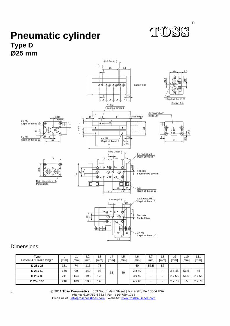
Type D Ø25 mm
L7
25
L1025
6 H9 Depth 6
1
L4
5 8.5
79
40
40
1 1
40 11
7
L11
40
L9
7
L9
Depth 62 x M8Depth of thread 15
Ø6 H9
37 9 .5
59
6 H9
L6L6L6
15
72358
.5
1
4 x M4Depth of thread 6
L
L3
Depth of thread 62 x M4
110 L1
9L2
A
A
L5
6 H
9
Stroke 50 bis 100mm
M6Depth of thread 10
29
6 x Rampa M8Depth of thread 7
Top side
6 H
9
29
9.5
Depth of thread 2041
Air connections2 x R 1/8"
29.5
15
60
Stroke length
Section A-A
Bottom side
15
40
M8
Ø6.
6
Ø11
2180 8.
530
.5
V
R
101
L8
2 x M6Depth of thread 15
7
6 H9 Depth 6
7
Retr. dimensions ofPiston plate
6 H9 Depth 5 4 x Rampa M8Depth of thread 7
Top sideStroke 25mm
2 x M6Depth of thread 10
Dimensions:
Type Piston Ø / Stroke length
L L1 L2 L3 L4 L5 L6 L7 L8 L9 L10 L11 [mm] [mm] [mm] [mm] [mm] [mm] [mm] [mm] [mm] [mm] [mm] [mm]
D 25 / 25 131 74 115 73
53
40
40 57,5 86 - - -
D 25 / 50 156 99 140 98 2 x 40 - - 2 x 45 51,5 45
D 25 / 80 211 154 195 128 3 x 40 - - 2 x 55 56,5 2 x 55
D 25 / 100 246 189 230 148 4 x 40 - - 2 x 70 55 2 x 70
Pneumatic cylinder
© 2011 Toss Pneumatics | 539 South Main Street | Nazareth, PA 18064 USA
Phone: 610-759-8883 | Fax: 610-759-1766
Email us at: [email protected] Website: www.tossballslides.com
5
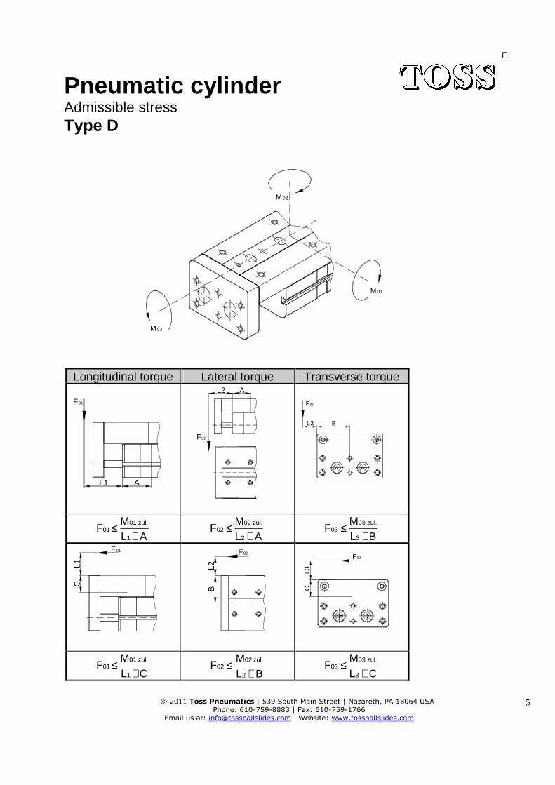
Admissible stress Type D
M03
M01
M02
Longitudinal torque Lateral torque Transverse torque
F01
L1 A
F02
L2 A
L3 B
F03
FML A
0101 zul.
1≤
+ F
ML A
0202 zul.
2≤
+ F
ML B
0303 zul.
3≤
+
CL1
F01
BL2
F02
CL 3
F03
FML C
0101 zul.
1≤
+
BLM
F2
zul. 0202
+≤ F
ML C
0303 zul.
3≤
+

Pneumatic cylinder
© 2011 Toss Pneumatics | 539 South Main Street | Nazareth, PA 18064 USA
Phone: 610-759-8883 | Fax: 610-759-1766
Email us at: [email protected] Website: www.tossballslides.com
6
Admissible stress
Stroke length [mm] 10 25 50 80 100 Ø / Type M1/M2
Nm M3 Nm
M1/M2 Nm
M3 Nm
M1/M2 Nm
M3 Nm
M1/M2 Nm
M3 Nm
M1/M2 Nm
M3 Nm
16 - D 11,2 9,3 10,4 8,17 14,0 10,5 25,0 18,6 30,0 22,1 20 - D 11,2 9,3 10,4 8,17 14,0 10,5 25,0 18,6 30,0 22,1 25 - D - - 96,0 62,8 91,1 62,8 158,6 107,4 187,2 125,6
Correction factors:
Ø / Type Stroke length A B C Ø / Type Stroke length A B C [mm] [mm] [mm] [mm] [mm] [mm] [mm] [mm] 10 28 25 37,5
16 - D 25 33 25 - D 50 50 40 15,5 20 - D 50 50,5 34 11 80 81,25
80 83 100 94,75 100 100,5
Example of calculation:
Given qyt: 20 - D with a stroke length of 80 mm Lever arm L1 = 40 mm = 0,04 m Longitudinal torque M1 = 25 Nm Correction factor A = 83 mm = 0,083 m
Required qty: N 203m 0,083m 0,04
Nm 25AL
MF
1
11 =
+=
+≤
F1
L1 A
Stress - longitudinal torque M1
Pneumatic cylinder
© 2011 Toss Pneumatics | 539 South Main Street | Nazareth, PA 18064 USA
Phone: 610-759-8883 | Fax: 610-759-1766
Email us at: [email protected] Website: www.tossballslides.com
7
All data based on tests conducted by Toss.
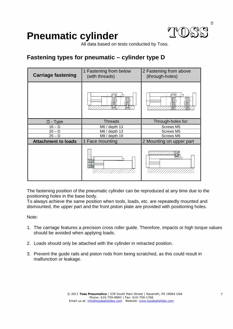
Fastening types for pneumatic – cylinder type D
Carriage fastening 1 Fastening from below (with threads)
2 Fastening from above (through-holes)
∅∅∅∅ - Type Threads Through-holes for:
16 – D M6 / depth 13 Screws M5 20 – D M6 / depth 13 Screws M5 25 – D M8 / depth 19 Screws M6
Attachment t o loads 1 Face mounting 2 Mounting on upper part
The fastening position of the pneumatic cylinder can be reproduced at any time due to the positioning holes in the base body. To always achieve the same position when tools, loads, etc. are repeatedly mounted and dismounted, the upper part and the front piston plate are provided with positioning holes. Note: 1. The carriage features a precision cross roller guide. Therefore, impacts or high torque values
should be avoided when applying loads. 2. Loads should only be attached with the cylinder in retracted position. 3. Prevent the guide rails and piston rods from being scratched, as this could result in
malfunction or leakage.
Pneumatic cylinder
© 2011 Toss Pneumatics | 539 South Main Street | Nazareth, PA 18064 USA
Phone: 610-759-8883 | Fax: 610-759-1766
Email us at: [email protected] Website: www.tossballslides.com
8
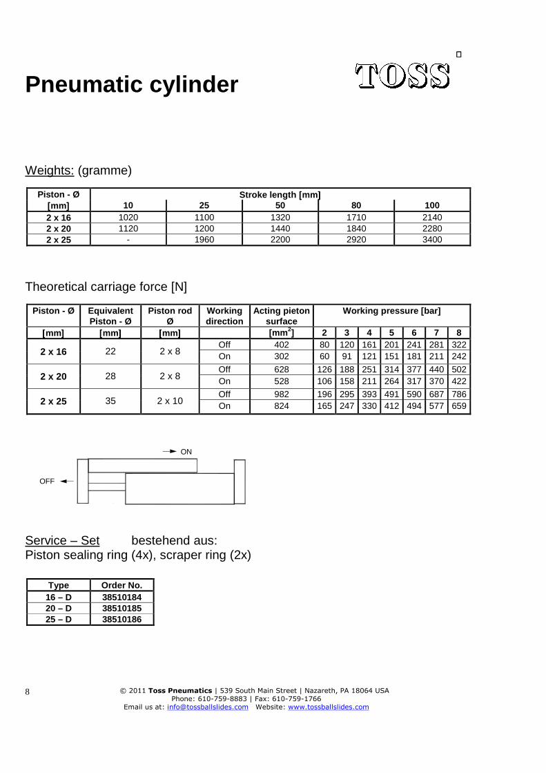
Weights: (gramme)
Piston - Ø Stroke length [[[[mm ]]]] [[[[mm ]]]] 10 25 50 80 100 2 x 16 1020 1100 1320 1710 2140 2 x 20 1120 1200 1440 1840 2280 2 x 25 - 1960 2200 2920 3400
Theoretical carriage force [N]
Piston - Ø
Equivalent Piston - Ø
Piston rod Ø
Working direction
Acting pieton surface
Working pressure [bar]
[[[[mm ]]]] [[[[mm ]]]] [[[[mm ]]]] [mm 2] 2 3 4 5 6 7 8
2 x 16 22 2 x 8 Off 402 80 120 161 201 241 281 322 On 302 60 91 121 151 181 211 242
2 x 20 28 2 x 8 Off 628 126 188 251 314 377 440 502 On 528 106 158 211 264 317 370 422
2 x 25 35 2 x 10 Off 982 196 295 393 491 590 687 786 On 824 165 247 330 412 494 577 659
OFF
ON
Service – Set bestehend aus: Piston sealing ring (4x), scraper ring (2x)
Type Order No. 16 – D 38510184 20 – D 38510185 25 – D 38510186

Pneumatic cylinder
© 2011 Toss Pneumatics | 539 South Main Street | Nazareth, PA 18064 USA
Phone: 610-759-8883 | Fax: 610-759-1766
Email us at: [email protected] Website: www.tossballslides.com
9
The supply includes fixed stops to be mounted on both sides with two stop pins and two counter-nuts.
Stroke length setting max. L1
Fixed stops
On request, we can supply additional hydraulic shock absorbers.
Shock absorbers
Stroke length cushioning max. L2
Ø / Type L1 L2 Ø / Type Order No.
[mm] [mm] Shock absorber Counter-nut 16 - D 5 10 16 - D 38510179 38510182 20 - D 5 10 20 - D 38510179 38510182 25 - D 5 16 25 - D 38510180 38510183
Pneumatic cylinder
© 2011 Toss Pneumatics | 539 South Main Street | Nazareth, PA 18064 USA
Phone: 610-759-8883 | Fax: 610-759-1766
Email us at: [email protected] Website: www.tossballslides.com
10
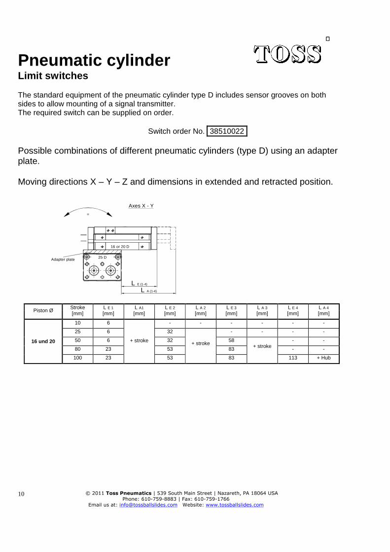
Limit switches The standard equipment of the pneumatic cylinder type D includes sensor grooves on both sides to allow mounting of a signal transmitter. The required switch can be supplied on order.
Switch order No. 38510022
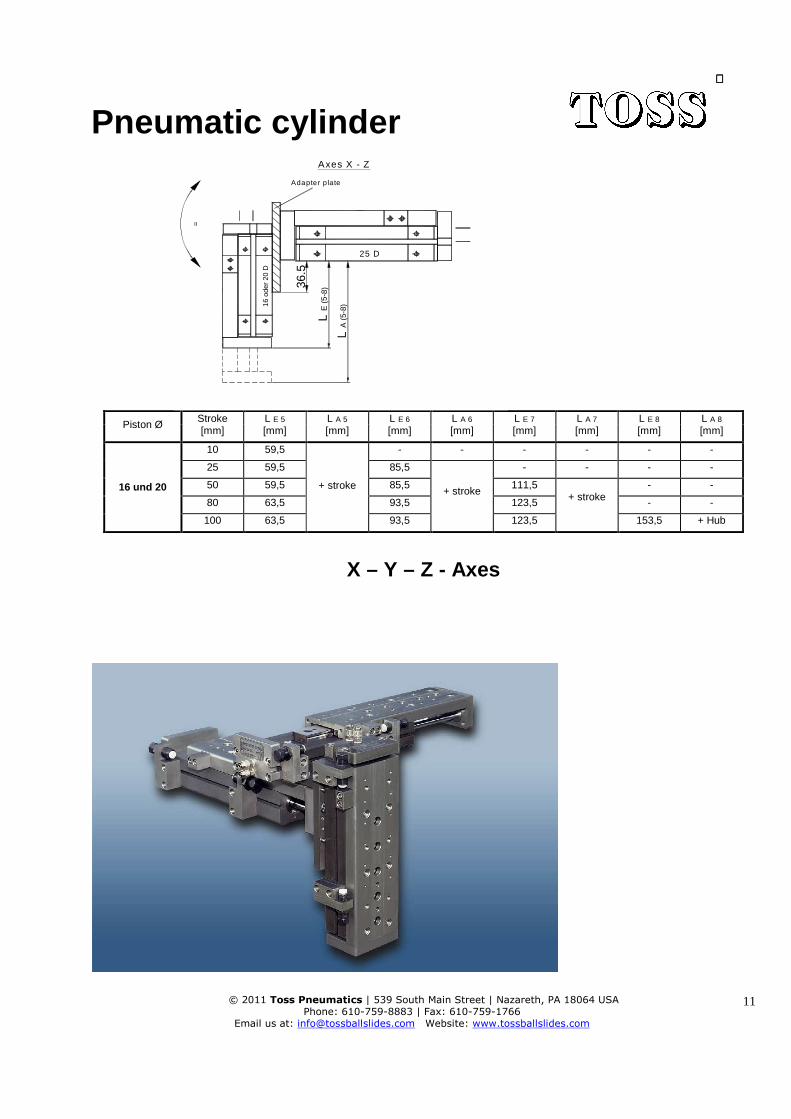
Possible combinations of different pneumatic cylinders (type D) using an adapter plate. Moving directions X – Y – Z and dimensions in extended and retracted position.
Piston Ø Stroke L E 1 L A1 L E 2 L A 2 L E 3 L A 3 L E 4 L A 4 [mm] [mm] [mm] [mm] [mm] [mm] [mm] [mm] [mm]
16 und 20
10 6
+ stroke
- - - - - -
25 6 32
+ stroke
- - - -
50 6 32 58 + stroke
- -
80 23 53 83 - -
100 23 53 83 113 + Hub
L E (1-4)
L A (1-4)
=
25 D
Axes X - Y
16 or 20 D
Adapter plate
Pneumatic cylinder
© 2011 Toss Pneumatics | 539 South Main Street | Nazareth, PA 18064 USA
Phone: 610-759-8883 | Fax: 610-759-1766
Email us at: [email protected] Website: www.tossballslides.com
11
Piston Ø Stroke L E 5 L A 5 L E 6 L A 6 L E 7 L A 7 L E 8 L A 8 [mm] [mm] [mm] [mm] [mm] [mm] [mm] [mm] [mm]
16 und 20
10 59,5
+ stroke
- - - - - -
25 59,5 85,5
+ stroke
- - - -
50 59,5 85,5 111,5 + stroke
- -
80 63,5 93,5 123,5 - -
100 63,5 93,5 123,5 153,5 + Hub
X – Y – Z - Axes
25 D
=
36.5
16 o
der
20 D
L E
(5-
8)
L A
(5-
8)
Axes X - Z
Adapter plate
Pneumatic cylinder
© 2011 Toss Pneumatics | 539 South Main Street | Nazareth, PA 18064 USA
Phone: 610-759-8883 | Fax: 610-759-1766
Email us at: [email protected] Website: www.tossballslides.com
12
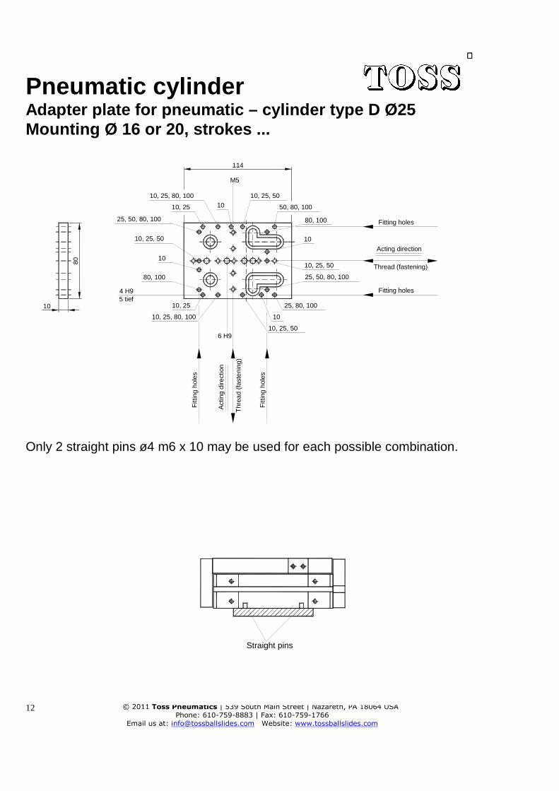
Adapter plate for pneumatic – cylinder type D Ø25 Mounting Ø 16 or 20, strokes ...
10, 25, 50
25, 80, 100
50, 80, 100
10
10, 25, 80, 100
10, 25
4 H95 tief
80, 100
6 H9
10
10, 25
10, 25, 80, 100
80
10, 25, 50
10
25, 50, 80, 100
M5
1010, 25, 50
114
25, 50, 80, 100
10, 25, 50
10
80, 100 Fitting holes
Acting direction
Thread (fastening)
Fitting holes
Fit t
ing
hole
s
Fitt
ing
hole
s
Act
ing
dire
ctio
n
Th r
ead
(fas
teni
ng)
Only 2 straight pins ø4 m6 x 10 may be used for each possible combination.
Straight pins
Pneumatic cylinder
© 2011 Toss Pneumatics | 539 South Main Street | Nazareth, PA 18064 USA
Phone: 610-759-8883 | Fax: 610-759-1766
Email us at: [email protected] Website: www.tossballslides.com
13
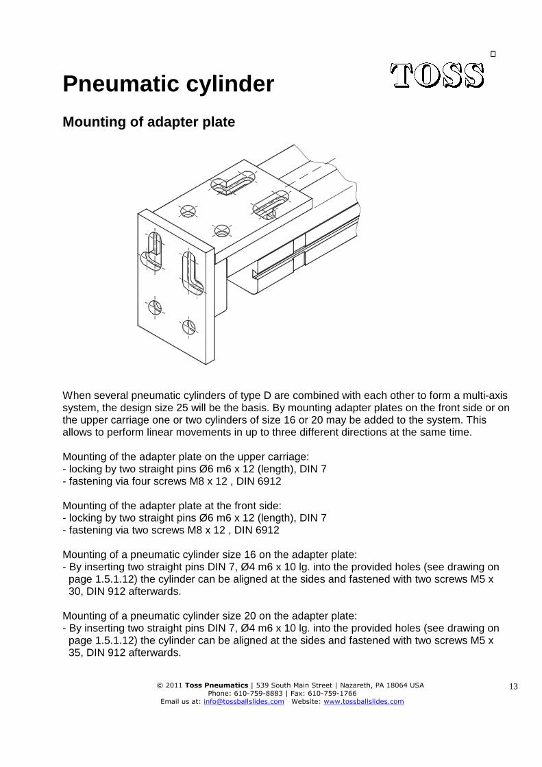
Mounting of adapter plate
When several pneumatic cylinders of type D are combined with each other to form a multi-axis system, the design size 25 will be the basis. By mounting adapter plates on the front side or on the upper carriage one or two cylinders of size 16 or 20 may be added to the system. This allows to perform linear movements in up to three different directions at the same time. Mounting of the adapter plate on the upper carriage: - locking by two straight pins Ø6 m6 x 12 (length), DIN 7 - fastening via four screws M8 x 12 , DIN 6912 Mounting of the adapter plate at the front side: - locking by two straight pins Ø6 m6 x 12 (length), DIN 7 - fastening via two screws M8 x 12 , DIN 6912 Mounting of a pneumatic cylinder size 16 on the adapter plate: - By inserting two straight pins DIN 7, Ø4 m6 x 10 lg. into the provided holes (see drawing on page 1.5.1.12) the cylinder can be aligned at the sides and fastened with two screws M5 x 30, DIN 912 afterwards. Mounting of a pneumatic cylinder size 20 on the adapter plate: - By inserting two straight pins DIN 7, Ø4 m6 x 10 lg. into the provided holes (see drawing on page 1.5.1.12) the cylinder can be aligned at the sides and fastened with two screws M5 x 35, DIN 912 afterwards.