pneudri midas maintenance manual -...
TRANSCRIPT
PNEUDRI MiDAS
MAINTENANCE MANUALDATE : 12Sep01 REV: 0
domnick hunter filters limited,Durham road, Birtley Co. Durham DH3 2SF, Tel: 091 410 5121 Telex: 537282 Telefax: 091 410 7621

Page 2 of 42
FOREWORDThe compressed air dryer systems have been designed and manufactured to ensure thatmaximum safety and performance is achieved. It is expected that users of these systemswill employ safe working practices and ensure that when installing, commissioning,operating or maintaining the equipment, any legal requirements are fulfilled. For example,in the UK, users should refer to the Health and Safety Act, 1974.
All ancillary equipment such as pipework, valves, fittings etc., must be suitable for thepressures and capacities involved.
Replacement parts are available from your distributor or the manufacturers ( see front pagefor information). The adoption of a regular servicing policy is strongly recommended andwill result in ensuring that a high performance is achieved. Serial numbers and customerorder numbers should be referred to in any communication. (Serial numbers can be foundon the identification plate attached to the dryer). The figure number and the appropriatediagram in this manual and the item number (shown in circle,) will also assist in partidentification.Any warranty will be invalidated if the dryer is not installed in accordance with themanufacturers recommendations or non-approved parts substituted. Substitute parts couldreduce the performance or service life in addition to creating potential hazards.
The manufacturers reserve the right to modify the contents of this manual without notice.The data given is a guideline to users and in no way binding on the manufacturers.
BEFORE SERVICING OR DISMANTLING ALL PRESSURE MUST BE RELEASEDFROM THE SYSTEM AND ITS ASSOCIATED PIPEWORK AND ANY ELECTRICALSUPPLY ISOLATED.
Page 3 of 42
Section
A1
A2
A3
A4
A5
A6
A7
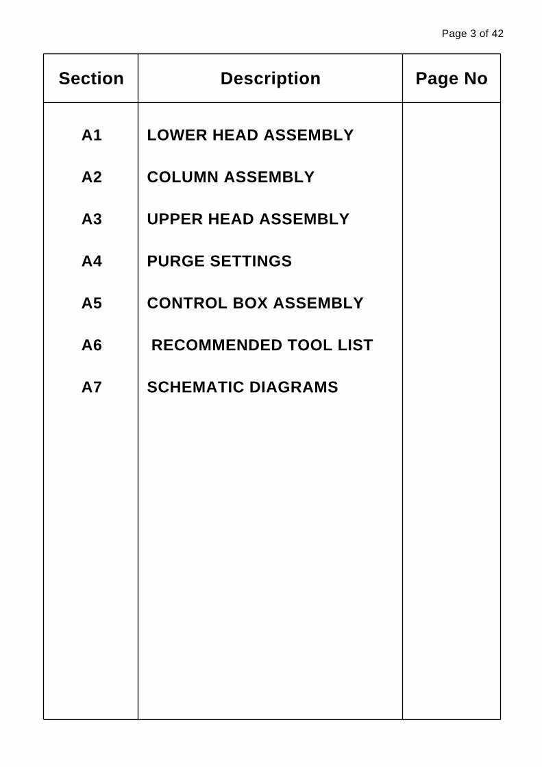
Description
LOWER HEAD ASSEMBLY
COLUMN ASSEMBLY
UPPER HEAD ASSEMBLY
PURGE SETTINGS
CONTROL BOX ASSEMBLY
RECOMMENDED TOOL LIST
SCHEMATIC DIAGRAMS
Page No
Page 4 of 42
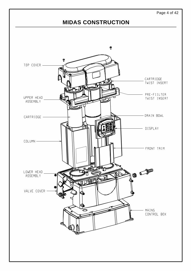
MIDAS CONSTRUCTION

Page 5 of 42
SECTION A1
LOWER HEAD ASSEMBLY
A1.1
A1.2
A1.3
A1.4
A1.5
Lower Head Removal
Silencer Removal
Inlet Ball and Retainer Removal
Solenoid Valve Removal
Lower Head Torque sequence
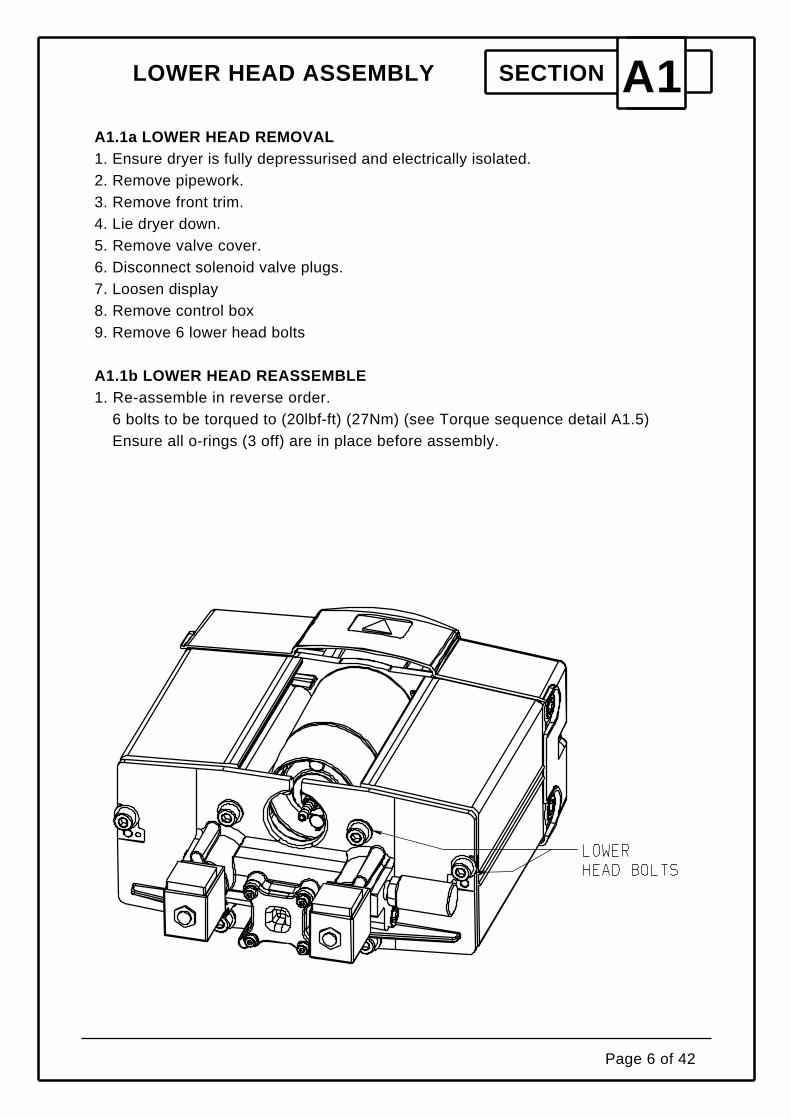
LOWER HEAD ASSEMBLY SECTION A1A1.1a LOWER HEAD REMOVAL1. Ensure dryer is fully depressurised and electrically isolated.2. Remove pipework.3. Remove front trim.4. Lie dryer down.5. Remove valve cover.6. Disconnect solenoid valve plugs.7. Loosen display8. Remove control box9. Remove 6 lower head bolts
A1.1b LOWER HEAD REASSEMBLE1. Re-assemble in reverse order.
6 bolts to be torqued to (20lbf-ft) (27Nm) (see Torque sequence detail A1.5)Ensure all o-rings (3 off) are in place before assembly.
Page 6 of 42

LOWER HEAD ASSEMBLY SECTION A1A1.2a SILENCER REPLACEMENT1. Ensure dryer is fully depressurised and electrically isolated.2. Remove pipework.3. Lie dryer down.4. Remove valve cover.5. Remove silencer.
A1.2b SILENCER REASSEMBLE1. Re-assemble in reverse order
Page 7 of 42

LOWER HEAD ASSEMBLY SECTION A1A1.3a INLET BALL RETAINER REPLACEMENT1. Ensure dryer is fully depressurised and electrically isolated.2. Remove pipework.3. Remove front trim.4. Lie dryer down.5. Loosen and remove display.6. Remove valve cover.7. Disconnect solenoid valve plugs.8. Remove 4 bolts for ball retainer.9. Remove ball.A1.3b RE-ASSEMBLY Of INLET BALL RETAINER1. Re-assemble in reverse order as above
Torque setting for 4 bolts (2.2lbf-ft) (3 Nm)
Page 8 of 42

LOWER HEAD ASSEMBLY SECTION A1A1.4a SOLENOID VALVE REPLACEMENT1. Ensure dryer is fully depressurised and electrically isolated.2. Remove pipework.3. Remove front trim.4. Lie dryer down.5. Loosen display6. Remove valve cover.7. Disconnect solenoid valve plugs.8. Remove solenoid block retainer (clip or nut)9. Remove valve stem and plunger.A1.4b RE-ASSEMBLY OF SOLENOID VALVE1. Re-assemble in reverse order as above
Torque setting on valve stems (3.6lbf-ft) (5 Nm)
Page 9 of 42

LOWER HEAD ASSEMBLY SECTION A1A1.5 Torque
Torque all bolts to 27N/M
Page 10 of 42

Page 11 of 42
SECTION A2
COLUMN ASSEMBLY
A2.1
A2.2
A2.3
Desiccant Cartridge Replacement
Column Replacement
Torque sequence & Settings

COLUMN ASSEMBLY SECTION A2A2.1a CARTRIDGE REPLACEMENT
1. Ensure dryer is fully depressurised.2. Remove top cover.3. Remove cartridge twist inserts.(Anti-clockwise)4. Remove cartridge from inserts
A2.1b CARTRIDGE REASSEMBLY1. Reassemble in reverse order1. Ensure o-ring on cartridge is in place.
Page 12 of 42
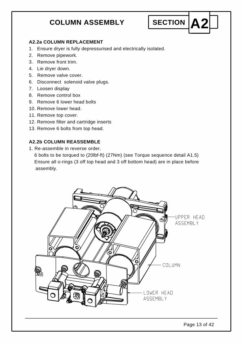
COLUMN ASSEMBLY SECTION A2A2.2a COLUMN REPLACEMENT1. Ensure dryer is fully depressurised and electrically isolated.2. Remove pipework.3. Remove front trim.4. Lie dryer down.5. Remove valve cover.6. Disconnect solenoid valve plugs.7. Loosen display8. Remove control box9. Remove 6 lower head bolts10. Remove lower head.11. Remove top cover.12. Remove filter and cartridge inserts13. Remove 6 bolts from top head.
A2.2b COLUMN REASSEMBLE1. Re-assemble in reverse order.
6 bolts to be torqued to (20lbf-ft) (27Nm) (see Torque sequence detail A1.5)Ensure all o-rings (3 off top head and 3 off bottom head) are in place beforeassembly.
Page 13 of 42

COLUMN ASSEMBLY SECTION A2A2.3 Torque Settings
Torque all bolts to 27 N/M
Page 14 of 42
Page 15 of 42
SECTION A3
UPPER HEAD ASSEMBLY
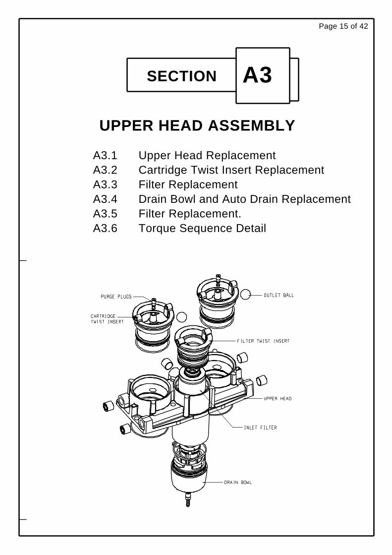
A3.1A3.2A3.3A3.4A3.5A3.6
Upper Head ReplacementCartridge Twist Insert ReplacementFilter ReplacementDrain Bowl and Auto Drain ReplacementFilter Replacement.Torque Sequence Detail
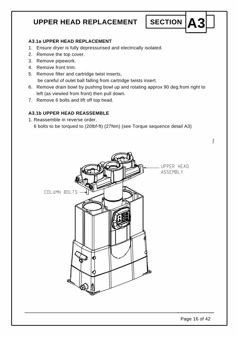
UPPER HEAD REPLACEMENT SECTION A3A3.1a UPPER HEAD REPLACEMENT1. Ensure dryer is fully depressurised and electrically isolated.2. Remove the top cover.3. Remove pipework.4. Remove front trim.5. Remove filter and cartridge twist inserts,
be careful of oulet ball falling from cartridge twists insert.6. Remove drain bowl by pushing bowl up and rotating approx 90 deg.from right to
left (as viewied from front) then pull down.7. Remove 6 bolts and lift off top head.
A3.1b UPPER HEAD REASSEMBLE1. Reassemble in reverse order.
6 bolts to be torqued to (20lbf-ft) (27Nm) (see Torque sequence detail A3)
Page 16 of 42

UPPER HEAD REPLACEMENT SECTION A3A3.2a CARTRIDGE TWIST INSERT REPLACEMENT1. Ensure dryer is fully depressurised and electrically isolated.2. Remove the top cover.3. Remove cartridge twist insert (Anti-clockwise)4. Remove cartridge from insert.5. Remove puge plug.
A3.2b CARTRIDGE TWIST INSERT REASSEMBLE1. Reassemble in reverse order.2. Set purge flow.
Page 17 of 42

UPPER HEAD REPLACEMENT SECTION A3A3.3a FILTER TWIST INSERT REPLACEMENT1. Ensure dryer is fully depressurised and electrically isolated.2. Remove the top cover.3. Remove filter twist insert.(Anti-clockwise)4. Unscrew filter.
A3.3b FILTER TWIST INSERT REASSEMBLE1. Reassemble in reverse order.
Page 18 of 42

UPPER HEAD REPLACEMENT SECTION A3A3.4a DRAIN BOWL and AUTO DRAIN REPLACEMENT1. Ensure dryer is fully depressurised and electrically isolated.2. Remove front trim.3 Loosen display pozi screws4. Unlock and remove drain bowl ,by first pushing up then rotating from left to right
as viewed from the front. Pull drain down and remove.5. Remove auto drain - (Note nut of auto drain turns into housing to remove auto
drain)
A3.4b DRAIN BOWL and AUTO DRAIN REASSEMBLE1. Reassemble in reverse order.
Auto drain to be torqued to (2.5Nm) (1.8lbf.ft)
Page 19 of 42

UPPER HEAD REPLACEMENT SECTION A3A3.5a FILTER REPLACEMENT1. Ensure dryer is fully depressurised and electrically isolated.2. Remove the top cover.3. Remove filter twist insert.(Anti-clockwise)4. Unscrew filter.
A3.5b FILTER REASSEMBLY1. Reassemble in reverse order.
Page 20 of 42

UPPER HEAD REPLACEMENT SECTION A3A3.6a TORQUE SEQUENCE DETAIL
Page 21 of 42
Page 22 of 42
SECTION A4
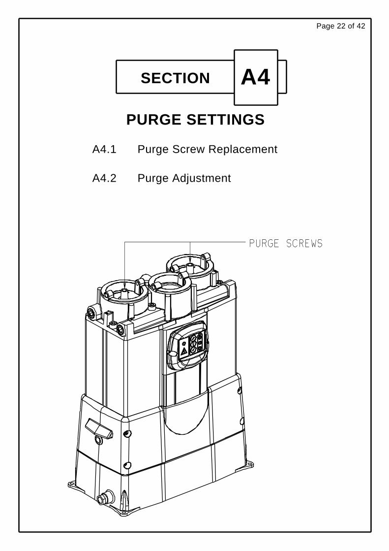
PURGE SETTINGS
A4.1
A4.2
Purge Screw Replacement
Purge Adjustment

SECTION A4A4.1a Purge Screw Replacement.
1. Ensure dryer is fully depressurised and electrically isolated2. Remove top cover.3. Unscrew purge plugs.
A4.1b Purge Screw Reassembly1. Reassemble ensuring purge is set correctly. See A4.2
Page 23 of 42

SECTION A4A4.2 PURGE FLOW
DRYER MODEL
DAS 1
DAS 2
DAS 3
DAS 4
DAS 5
DAS 6
DAS 7
0.6
1.0
1.6
2.0
2.6
3.0
4.0
MUST BE SET AT MINIMUM SYSTEM PRESSURE
SCFM L/MIN
17.0
28.32
45.31
56.64
73.63
84.95
113.30
PURGE SETTING
1. Gain access to the lower head by removing the front valve cover.2. Replace silencer 1/4"bsp fitting with a suitable fitting to connect a flow
meter3. Allow dryer to cycle at its minimum pressure. (Note dryer to be in
upright position)4. Do not connect the flow meter until straight after a blow down has
occured.5. After a blow down connect flow meter and adjust one of the purge
screws. Once set to required flow remove meter and allow blow downof other chamber.
6. Set flow to this chamber.7. remove fitting and reconnect silencer.8. Reassemble valve covers.
Page 24 of 42

Page 25 of 42
SECTION A5
CONTROL BOX ASSEMBLY
A5.1
A5.2
A5.3
A5.4
A5.5
A5.6
A5.7
A5.8
A5.9
A5.10
A5.11
Exploded View of Control Box
Control Box Removal
Timer Replacement
Display Replacement
Transformer Replacement
Fuse Replacement
Solenoid Cable Replacement
Control Box Replacement
Relay Replacement
Timer Configuration
Sevice Reset Sequence

SECTION A5A5.1 EXPLODED VIEW OF CONTROL BOX
Page 26 of 42

SECTION A5A5.2 CONTROL BOX REMOVAL
A5.2a CONTROLBOX REMOVAL1. Ensure dryer is fully depressurised and electrically isolated.2. Remove pipework.3. Remove front trim.4. Lie dryer down.5. Remove valve cover.6. Disconnect solenoid valve plugs.7. Loosen display8. Remove control box
A5.2b CONTROL BOX REASSEMBLE1. Reassemble as above in reverse order
Page 27 of 42

SECTION A5A5.3aTIMER REPLACEMENT
1. Ensure dryer is fully depressurised and electrically isolated.2. Remove pipework.3. Remove front trim.4. Lie dryer down.5. Remove valve cover.6. Disconnect solenoid valve plugs.7. Loosen display8. Remove control box9. Remove 9 screws from timer base plate and open control box.10. Remove all leads from timer board.11. Remove 4 nuts from timer board.12. Remove timer board.
A5.3b TIMER REASSEMBLE1. Reassemble as above in reverse order. 4 nuts to be torqued to (0.5Nm) (0.4lbf.ft)
Pozi retaining screws to be torqued to (0.5Nm) (0.4lbf.ft) See wiring schematic forcable positions.
Page 28 of 42

SECTION A5A5.4a DISPLAY REPLACEMENT
1. Ensure dryer is fully depressurised and electrically isolated.2. Remove pipework.3. Remove front trim.4. Lie dryer down.5. Remove valve cover.6. Disconnect solenoid valve plugs.7. Loosen display8. Remove control box9. Remove 9 screws from timer base plate, and open control box.10. Disconnect display leads from timer board.11. Loosen cable gland nut and remove display.
A5.4b DISPLAY REASSEMBLE1. Reassemble as above in reverse order.See wiring schematic for cable positions.
Pozi retaining screws to be torqued to (0.5Nm) (0.4lbf.ft)
Page 29 of 42
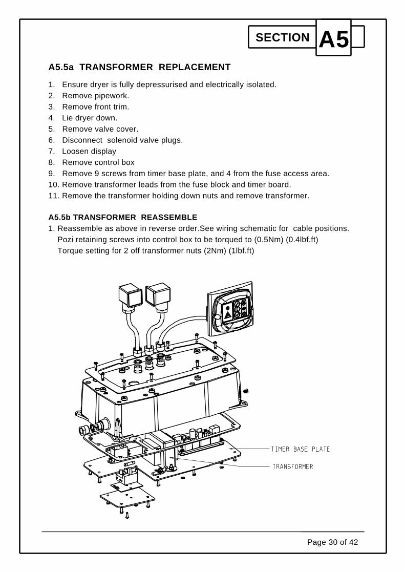
SECTION A5A5.5a TRANSFORMER REPLACEMENT
1. Ensure dryer is fully depressurised and electrically isolated.2. Remove pipework.3. Remove front trim.4. Lie dryer down.5. Remove valve cover.6. Disconnect solenoid valve plugs.7. Loosen display8. Remove control box9. Remove 9 screws from timer base plate, and 4 from the fuse access area.10. Remove transformer leads from the fuse block and timer board.11. Remove the transformer holding down nuts and remove transformer.
A5.5b TRANSFORMER REASSEMBLE1. Reassemble as above in reverse order.See wiring schematic for cable positions.
Pozi retaining screws into control box to be torqued to (0.5Nm) (0.4lbf.ft)Torque setting for 2 off transformer nuts (2Nm) (1lbf.ft)
Page 30 of 42

SECTION A5A5.6a FUSE REPLACEMENT
1. Ensure dryer is fully depressurised and electrically isolated.2. Remove pipework.3. Lie dryer down.4. Remove 4 screws on small plate.5. Remove fuse from fuse holder.
A5.6b FUSE REASSEMBLE1. Reassemble as above in reverse order.
Pozi retaining screws into to be torqued to (0.5Nm) (0.4lbf.ft)
Page 31 of 42

SECTION A5A5.7a SOLENOID CABLE REPLACEMENT
1. Ensure dryer is fully depressurised and electrically isolated.2. Remove pipework.3. Remove front trim.4. Lie dryer down.5. Remove valve cover.6. Disconnect solenoid valve plugs.7. Loosen display8. Remove control box9. Remove 9 screws from timer base plate, and open control box.10. Disconnect soleniod cables from timer board.11. Loosen cable gland nuts and remove solenoid cables
A5.7b SOLENOID CABLE REASSEMBLE1. Reassemble as above in reverse order.See wiring schematic for cable positions.
Pozi retaining screws to be torqued to (0.5Nm) (0.4lbf.ft)
Page 32 of 42
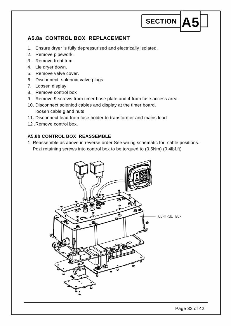
SECTION A5A5.8a CONTROL BOX REPLACEMENT
1. Ensure dryer is fully depressurised and electrically isolated.2. Remove pipework.3. Remove front trim.4. Lie dryer down.5. Remove valve cover.6. Disconnect solenoid valve plugs.7. Loosen display8. Remove control box9. Remove 9 screws from timer base plate and 4 from fuse access area.10. Disconnect soleniod cables and display at the timer board,
loosen cable gland nuts11. Disconnect lead from fuse holder to transformer and mains lead12 .Remove control box.
A5.8b CONTROL BOX REASSEMBLE1. Reassemble as above in reverse order.See wiring schematic for cable positions.
Pozi retaining screws into control box to be torqued to (0.5Nm) (0.4lbf.ft)
Page 33 of 42
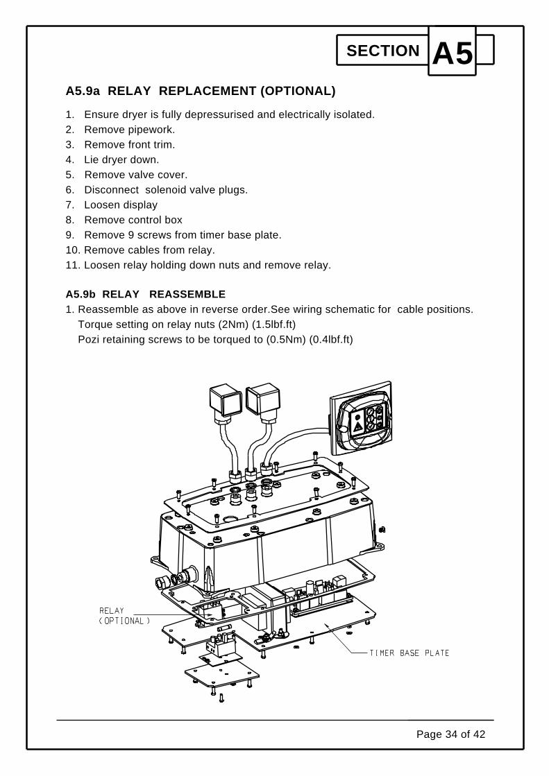
SECTION A5A5.9a RELAY REPLACEMENT (OPTIONAL)
1. Ensure dryer is fully depressurised and electrically isolated.2. Remove pipework.3. Remove front trim.4. Lie dryer down.5. Remove valve cover.6. Disconnect solenoid valve plugs.7. Loosen display8. Remove control box9. Remove 9 screws from timer base plate.10. Remove cables from relay.11. Loosen relay holding down nuts and remove relay.
A5.9b RELAY REASSEMBLE1. Reassemble as above in reverse order.See wiring schematic for cable positions.
Torque setting on relay nuts (2Nm) (1.5lbf.ft)Pozi retaining screws to be torqued to (0.5Nm) (0.4lbf.ft)
Page 34 of 42
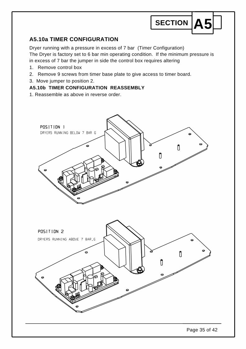
SECTION A5A5.10a TIMER CONFIGURATION
Dryer running with a pressure in excess of 7 bar (Timer Configuration)The Dryer is factory set to 6 bar min operating condition. If the minimum pressure isin excess of 7 bar the jumper in side the control box requires altering1. Remove control box2. Remove 9 screws from timer base plate to give access to timer board.3. Move jumper to position 2.A5.10b TIMER CONFIGURATION REASSEMBLY1. Reassemble as above in reverse order.
Page 35 of 42

SECTION A5A5.11 SERVICE RESET SEQUENCE
Once the dryer has been serviced and all pipework connected, the timer boardrequires resetting.To reset the timer do not switch on the air.Remove the reset button on the control box, Insert a small terminal driver in to thehole and depress and hold the reset button.Switch the mains power on holding the reset button for 5 seconds.Remove ternminal driver and switch off mains.Wait 5 seconds before commencing start up sequence of dryer and replace resetbutton.
Page 36 of 42

Page 37 of 42
SECTION A6
RECOMMENDED TOOL LIST

SECTION A6Recommended Tool List
SOCKETS. 5.5mm 7.0mm and 16.0mmALLEN KEY SOCKETS. 6mm and 8mmFLAT BLADE SCEWDRIVERPOZI SCREWDRIVERFLAT BLADE TERMINAL DRIVEWIRE STRIPPERSPLIERSTORQE DRIVER (0.6NM)TORQUE WRENCH (5-40Nm)TOGGLE BAR 5dia x 300mm longALLEN KEY 4mmALLEN KEY 3/16"SPANNER 17mmSPANNER 14mm6" ADJUSTABLE SPANNERGREASEPTFE TAPEDRAIN BOWL SPANNERTUBE CUTTERS
Page 38 of 42

Page 39 of 42
SECTION A7
SCHEMATIC DIAGRAMS.
A7.1
A7.2
A7.3
Wiring Schematic (230V)
Wiring Schematic (115V)
Piping and Instrumentation Schematic
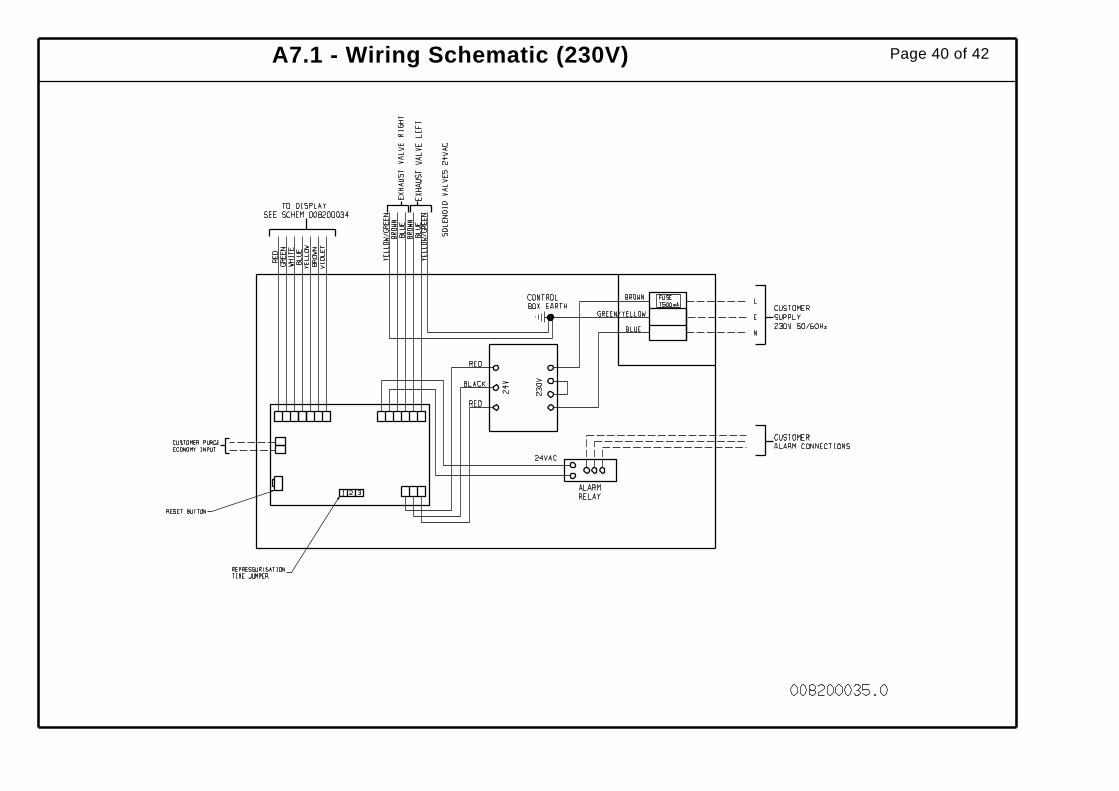
A7.1 - Wiring Schematic (230V) Page 40 of 42

A7.2 - Wiring Schematic (115V) Page 41 of 42
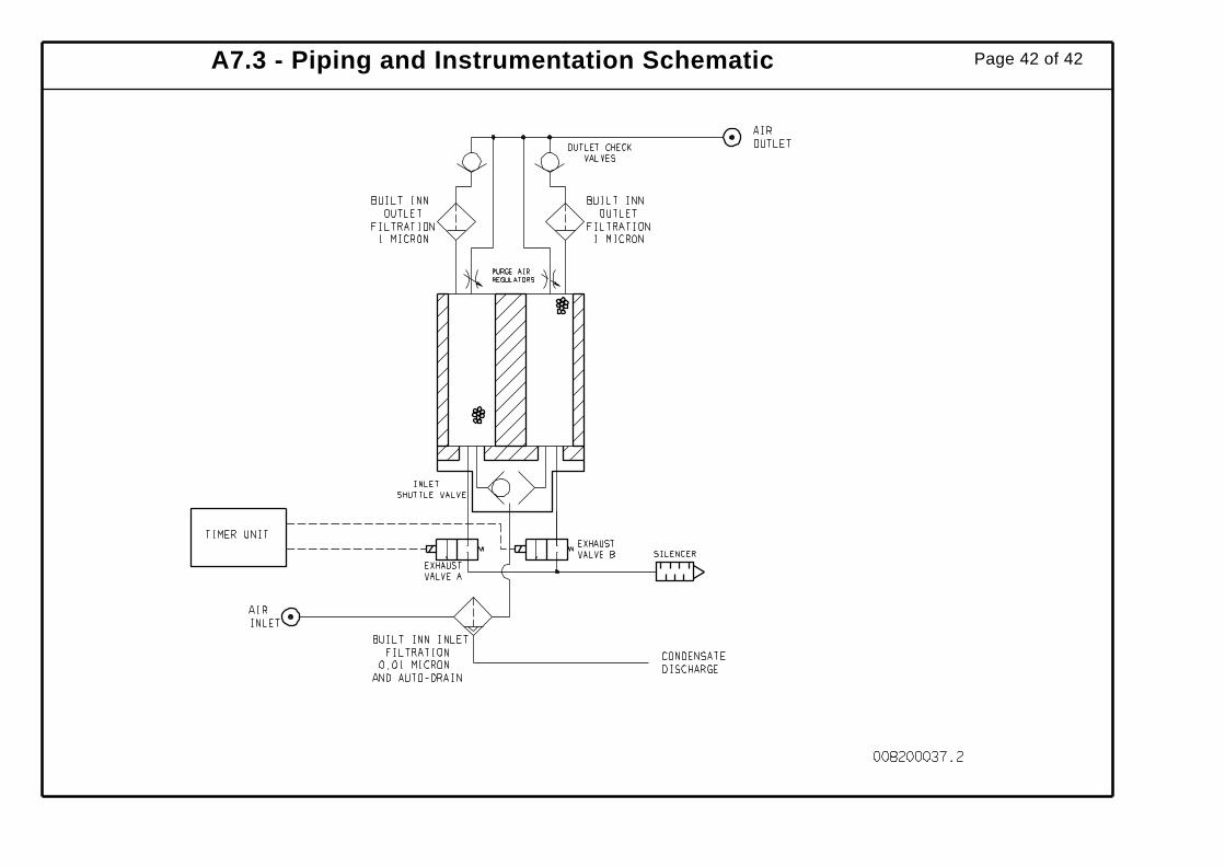
A7.3 - Piping and Instrumentation Schematic Page 42 of 42