pneg-1162cex - ce compliant gsi grain stir-ator · • do not operate stir-ator unless shut off...
TRANSCRIPT
PNEG-1162CEX
CE Compliant GSI Grain Stir-Ator
Owner’s Manual
PNEG-1162CEXVersion: 2.1
Date: 08-12-16
2 PNEG-1162CEX CE Compliant GSI Grain Stir-Ator
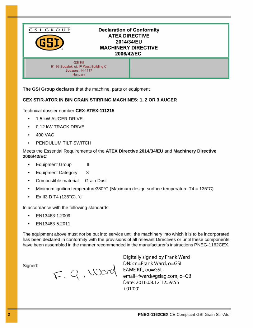
Declaration of ConformityATEX DIRECTIVE
2014/34/EUMACHINERY DIRECTIVE
2006/42/EC GSI Kft
91-93 Budafoki ut, IP-West Building CBudapest, H-1117
Hungary
The GSI Group declares that the machine, parts or equipment
CEX STIR-ATOR IN BIN GRAIN STIRRING MACHINES: 1, 2 OR 3 AUGER
Technical dossier number CEX-ATEX-111215
• 1.5 kW AUGER DRIVE
• 0.12 kW TRACK DRIVE
• 400 VAC
• PENDULUM TILT SWITCH
Meets the Essential Requirements of the ATEX Directive 2014/34/EU and Machinery Directive2006/42/EC
• Equipment Group II
• Equipment Category 3
• Combustible material Grain Dust
• Minimum ignition temperature380°C (Maximum design surface temperature T4 = 135°C)
• Ex II3 D T4 (135°C). ‘c’
In accordance with the following standards:
• EN13463-1:2009
• EN13463-5:2011
The equipment above must not be put into service until the machinery into which it is to be incorporatedhas been declared in conformity with the provisions of all relevant Directives or until these componentshave been assembled in the manner recommended in the manufacturer’s instructions PNEG-1162CEX.
Signed:
Table of Contents
PNEG-1162CEX CE Compliant GSI Grain Stir-Ator 3
ContentsChapter 1 Safety ..................................................................................................................................................... 4
Safety Guidelines .................................................................................................................................. 4Cautionary Symbols Definitions ............................................................................................................ 5Safety Cautions ..................................................................................................................................... 6Safety Sign-Off Sheet ......................................................................................................................... 10Maintenance ........................................................................................................................................ 11Installation ........................................................................................................................................... 12Operation ............................................................................................................................................ 12
Chapter 2 Safety Decals ...................................................................................................................................... 13
Chapter 3 Bin Loading ......................................................................................................................................... 15
Chapter 4 Installation .......................................................................................................................................... 16Track ................................................................................................................................................... 16Suspension Chain Installation ............................................................................................................. 17Stirrer Assembly .................................................................................................................................. 19Trolley Drive Assembly ....................................................................................................................... 30Center Suspension Assembly ............................................................................................................. 31Lifting Stirrer into Position ................................................................................................................... 32Connection to Power Supply ............................................................................................................... 33Stir Guard ............................................................................................................................................ 33Install Augers ...................................................................................................................................... 33
Chapter 5 Electrical Installation ......................................................................................................................... 36ATEX Rating ....................................................................................................................................... 36Control System .................................................................................................................................... 36Tilt Switch ............................................................................................................................................ 37Slip Ring .............................................................................................................................................. 37Wiring for Power Connections ............................................................................................................. 39Wiring for Safety Control Circuit .......................................................................................................... 40Wiring for Motor Control Circuits with Pendulum Tilt Switch ............................................................... 41Wiring for Slip Ring, Motor Connections and Tilt Switch Wiring for Pendulum Tilt Switch with 3 Phase Track Motor ................................................................................. 42Wiring for Slip Ring, Motor Connections and Tilt Switch Wiring for Pendulum Tilt Switch with 1 Phase Track Motor ................................................................................. 43Wiring for Motor Control Circuits with Electronic Tilt Switch ............................................................... 44Wiring for Slip Ring, Motor Connections and Tilt Switch Wiring for Electronic Tilt Switch with 3 Phase Track Motor ................................................................................. 45Wiring for Slip Ring, Motor Connections and Tilt Switch Wiring for Electronic Tilt Switch with 1 Phase Track Motor ................................................................................. 46Running Cables on Stir-Ator ............................................................................................................... 47Commisioning ..................................................................................................................................... 49Setting Up Tilt Switch Operation ......................................................................................................... 50
Chapter 6 Start-Up ............................................................................................................................................... 52Start-Up in a Full Bin ........................................................................................................................... 52
Chapter 7 Parts List ............................................................................................................................................. 53Metric Stir-Ator Assembly .................................................................................................................... 54CE Stir-Ator Yoke Assembly ............................................................................................................... 56Frame End Inboard Weldment Assembly ........................................................................................... 58Frame Rail Bundle Assembly .............................................................................................................. 59Drive Arm Assembly ............................................................................................................................ 60CE Stir-Ator Triple Auger Trolley Assembly ........................................................................................ 61Suspension Bar Assembly .................................................................................................................. 62
Chapter 8 Warranty .............................................................................................................................................. 63

4 PNEG-1162CEX CE Compliant GSI Grain Stir-Ator
1. Safety
Safety Guidelines
Safety guidelines are general-to-specific safety rules that must be followed at all times. This manual is written to help you understand safe operating procedures and problems that can be encountered by the operator and other personnel when using this equipment. Save these safety guidelines for future reference.
As owner or operator, you are responsible for understanding the requirements, hazards, and precautions that exist and to inform others as required. Unqualified persons must stay out of the work area at all times.
Alterations must not be made to the equipment. Alterations can produce dangerous situations resulting in SERIOUS INJURY or DEATH.
This equipment must be installed in accordance with the current installation codes and applicable regulations, which must be carefully followed in all cases. Authorities having jurisdiction must be consulted before installations are made.
When necessary, you must consider the installation location relative to electrical, fuel and water utilities.
Personnel operating or working around equipment must read this manual. This manual must be delivered with equipment to its owner. Failure to read this manual and its safety instructions is a misuse of the equipment.
ST-0001-3
1. Safety
PNEG-1162CEX CE Compliant GSI Grain Stir-Ator 5
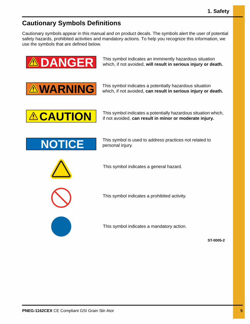
Cautionary Symbols Definitions
Cautionary symbols appear in this manual and on product decals. The symbols alert the user of potential safety hazards, prohibited activities and mandatory actions. To help you recognize this information, we use the symbols that are defined below.
DANGER
WARNING
CAUTION
NOTICE
This symbol indicates an imminently hazardous situation which, if not avoided, will result in serious injury or death.
This symbol indicates a potentially hazardous situation which, if not avoided, can result in serious injury or death.
This symbol indicates a potentially hazardous situation which, if not avoided, can result in minor or moderate injury.
This symbol is used to address practices not related to personal injury.
This symbol indicates a general hazard.
This symbol indicates a prohibited activity.
This symbol indicates a mandatory action.
ST-0005-2
1. Safety
6 PNEG-1162CEX CE Compliant GSI Grain Stir-Ator
Safety Cautions
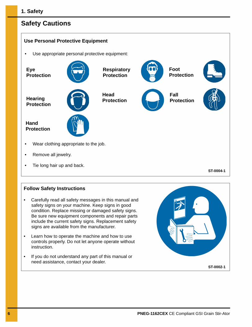
Use Personal Protective Equipment
Eye Protection
Hearing Protection
Hand Protection
Head Protection
Respiratory Protection
Foot Protection
Fall Protection
• Use appropriate personal protective equipment:
• Wear clothing appropriate to the job.
• Remove all jewelry.
• Tie long hair up and back.ST-0004-1
Follow Safety Instructions
• Carefully read all safety messages in this manual and safety signs on your machine. Keep signs in good condition. Replace missing or damaged safety signs. Be sure new equipment components and repair parts include the current safety signs. Replacement safety signs are available from the manufacturer.
• Learn how to operate the machine and how to use controls properly. Do not let anyone operate without instruction.
• If you do not understand any part of this manual or need assistance, contact your dealer.
ST-0002-1

1. Safety
PNEG-1162CEX CE Compliant GSI Grain Stir-Ator 7
Follow Safe Operating Procedures
• Do not operate Stir-Ator unless shut off chain has been properly installed and adjusted.
• Exercise care when starting Stir-Ator in a full bin of grain. Augers can be stuck in the grain causing damage to the Stir-Ator or bin.
• Operating the Stir-Ator during bin unloading can be beneficial to the unloading process as well as prevent auger damage.
• Do not bury the Stir-Ator. Burying the Stir-Ator will damage the bin and will void the warranty.
• Do not operate the Stir-Ator in an empty bin. Damage to the Stir-Ator and bin can result.
• When not operating the Stir-Ator for extended periods oftime or in some cases while emptying the bin, it is best to position the trolley at the bin wall to eliminate possible damage to the Stir-Ator or bin.
ST-0011-2
Stay Clear of Rotating Parts
• Do not enter the bin while the equipment is in operation.
• Entanglement in rotating augers will cause serious injury or death.
• Keep all guards and covers in place at all times.
• Lock-out power source before making adjustments, cleaning, or maintaining equipment. ST-0008-2
Operate Motor Properly
• All electrical connections must be made in accordance with applicable local codes (National Electric Code for the US, Canadian Electrical Code or EN60204 along with applicable European Directives for Europe). Make sure equipment and bins are properly grounded.
• Lock-out power before resetting motor overloads.
• Do not repetitively stop and start the drive in order to free a plugged condition. Jogging the drive in this manner can damage the equipment and drive components. ST-0009-3
1. Safety
8 PNEG-1162CEX CE Compliant GSI Grain Stir-Ator
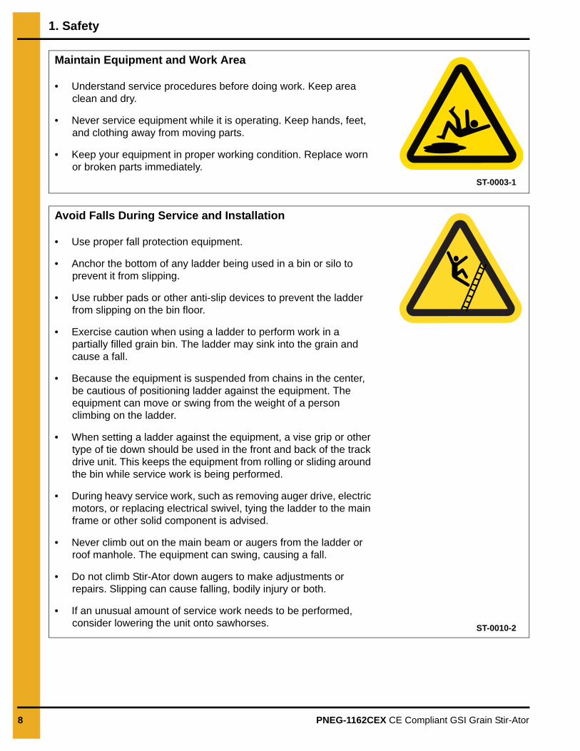
Maintain Equipment and Work Area
• Understand service procedures before doing work. Keep area clean and dry.
• Never service equipment while it is operating. Keep hands, feet, and clothing away from moving parts.
• Keep your equipment in proper working condition. Replace worn or broken parts immediately.
ST-0003-1
Avoid Falls During Service and Installation
• Use proper fall protection equipment.
• Anchor the bottom of any ladder being used in a bin or silo to prevent it from slipping.
• Use rubber pads or other anti-slip devices to prevent the ladder from slipping on the bin floor.
• Exercise caution when using a ladder to perform work in a partially filled grain bin. The ladder may sink into the grain and cause a fall.
• Because the equipment is suspended from chains in the center, be cautious of positioning ladder against the equipment. The equipment can move or swing from the weight of a person climbing on the ladder.
• When setting a ladder against the equipment, a vise grip or other type of tie down should be used in the front and back of the track drive unit. This keeps the equipment from rolling or sliding around the bin while service work is being performed.
• During heavy service work, such as removing auger drive, electric motors, or replacing electrical swivel, tying the ladder to the main frame or other solid component is advised.
• Never climb out on the main beam or augers from the ladder or roof manhole. The equipment can swing, causing a fall.
• Do not climb Stir-Ator down augers to make adjustments or repairs. Slipping can cause falling, bodily injury or both.
• If an unusual amount of service work needs to be performed, consider lowering the unit onto sawhorses. ST-0010-2
1. Safety
PNEG-1162CEX CE Compliant GSI Grain Stir-Ator 9
ST-0054-1
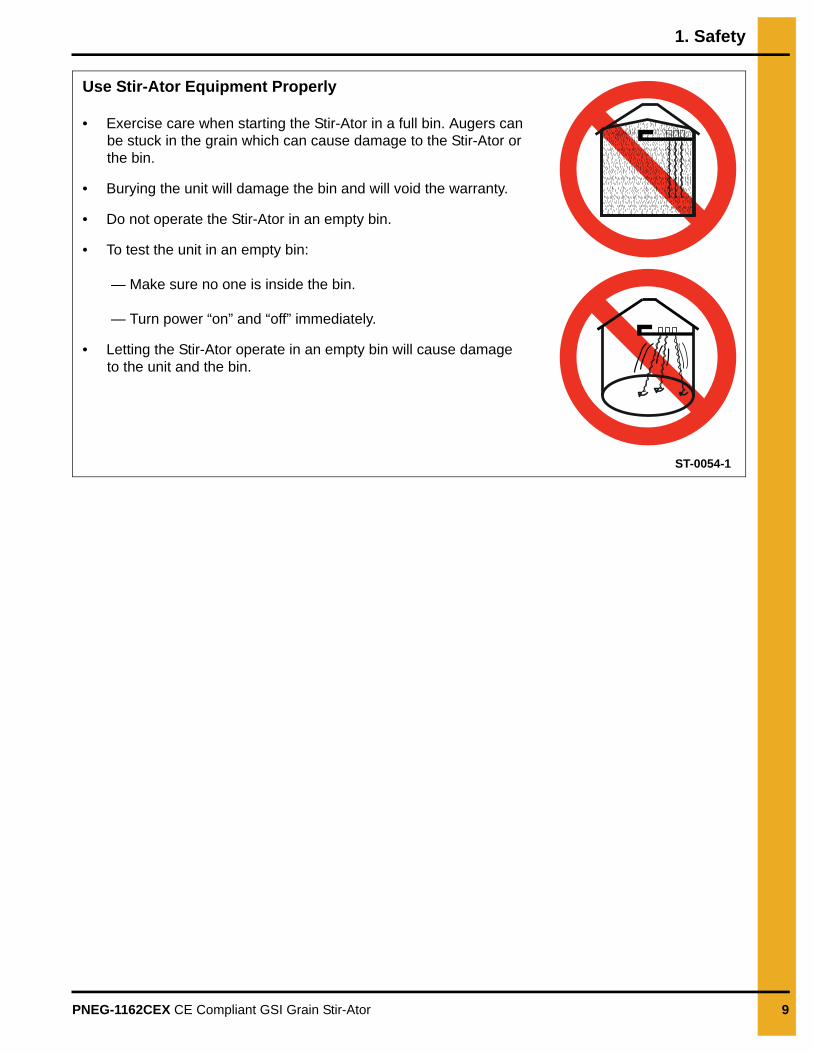
Use Stir-Ator Equipment Properly
• Exercise care when starting the Stir-Ator in a full bin. Augers can be stuck in the grain which can cause damage to the Stir-Ator or the bin.
• Burying the unit will damage the bin and will void the warranty.
• Do not operate the Stir-Ator in an empty bin.
• To test the unit in an empty bin:
— Make sure no one is inside the bin.
— Turn power “on” and “off” immediately.
• Letting the Stir-Ator operate in an empty bin will cause damage to the unit and the bin.

1. Safety
10 PNEG-1162CEX CE Compliant GSI Grain Stir-Ator
Safety Sign-Off Sheet
Below is a sign-off sheet that can be used to verify that all personnel have read and understood the safety instructions. This sign-off sheet is provided for your convenience and personal record keeping.
Date Employee Name Supervisor Name
ST-0007
1. Safety
PNEG-1162CEX CE Compliant GSI Grain Stir-Ator 11
Maintenance
1. Stop the Stir-Ator and all other machines BEFORE entering the bin.
2. Ensure the isolator switch is locked into the “OFF” position, with the only key in the possession.
3. Due to the height of the Stir-Ator in a bin, it is recommended that routine maintenance be carried out with the bin full, working off boards laid on top of the grain.
4. If access to the Stir-Ator is required when the bin is completely or partly empty, a safe means of access must be used, preferably using a working platform.
5. If using a ladder, DO NOT place the ladder against the Stir-Ator carriage unless it has been securely clamped on either side to prevent movement. Failure to do this could cause a fatal accident. Note that drying floors in grain stores may be slippery and therefore the ladder should be securely fixed before attempting to gain access.
6. When setting a ladder against the Stir-Ator, a vise grip or some type of tie-down should be used in the front and back of the track drive unit. This keeps the Stir-Ator from rolling or sliding around the bin while service work is being performed.
7. If an unusual amount of service work is to be performed on a Stir-Ator, removing the augers and lowering the unit to the floor of the bin may be the safest way to repair the unit.
8. Caution needs to be exercised when using a ladder to perform service work in a partially filled grain bin. The ladder can sink into the grain causing it to fall.
9. Notice of noise and dust hazard: The Stir-Ator runs at noise levels below 70 db and should not present any risk to hearing. Decals indicating the possibility of dust are provided in the owner’s manual bag and should be installed per the diagram shown on Pages 13 and 14. Dust may be created as a normal part of the stirring function of the Stir-Ator augers and although no person should be in the bin during the stirring operation, some residual dust may remain in the air after the Stir-Ator has been turned “OFF”. The level of dust will vary depending on the condition of the grain. Operator’s should assess the risk to themselves and others, as required in the EU under the Control of Substances Hazardous to Health Regulations. They should then implement appropriate control measures to reduce the risks to health.
10. If attending to stuck augers, NEVER attempt to release the auger without isolating the Stir-Ator first.
11. Before restarting the Stir-Ator, ensure that there is no one remaining in the bin and that the bin access door is locked/closed.
12. Remember to replace all guards before restarting.
When working on or around the Stir-Ator, it is essential that a safe system of work is strictly followed. Failure to do so may result in serious injury to the operator. Before carrying out any work on the Stir-Ator.
1. Safety
12 PNEG-1162CEX CE Compliant GSI Grain Stir-Ator
Installation1. The correct installation procedure is outlined in this manual.
2. Always install all recommended safety devices, such as safety isolators, grain level switches and door isolators. Failure to do so is a misuse of the equipment and may result in unsafe operation.
3. Always use the recommended flexible cable (type HO7). Failure to do so may result in damage to the electrical cable and risk electrical shock.
4. All electrical wiring should be in accordance to EN60204:2006.
5. All electrical installation must be carried out by a suitably qualified electrical engineer.
6. The system and all associated steel work must be safely earthed.
Operation1. Read and understand the owner’s manual.
2. Keep all safety shields in place.
3. Prior to inspecting, servicing, lubricating or adjusting the Stir-Ator, ensure the isolator switch is locked in the “OFF” position, with the only key in the possession.
4. Do not operate the Stir-Ator unless shut off chain has been properly installed and adjusted.
5. NEVER enter the bin while the Stir-Ator is in operation.
6. In the event that an auger becomes bound, the system should be switched OFF, isolated and locked OFF before any attempt to release the auger.
7. Operating the Stir-Ator during bin unloading can be beneficial to the unloading process as well as prevent auger damage.
8. DO NOT OVER FILL THE GRAIN BIN. BURYING THE STIRRER WILL DAMAGE BIN AND WILL VOID THE DESIGN III WARRANTY.
9. DO NOT OPERATE DESIGN III STIR-ATOR IN AN EMPTY BIN.
PNEG-1162CEX CE Compliant GSI Grain Stir-Ator 13
2. Safety Decals
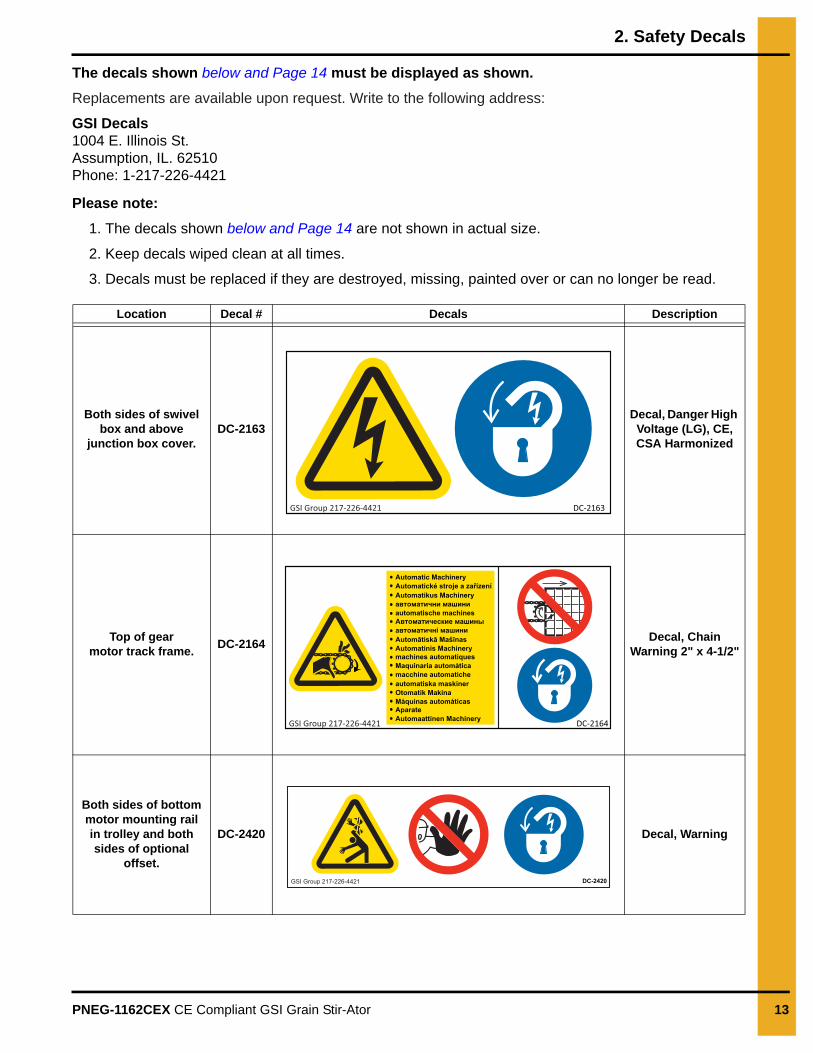
The decals shown below and Page 14 must be displayed as shown.
Replacements are available upon request. Write to the following address:
GSI Decals1004 E. Illinois St.Assumption, IL. 62510Phone: 1-217-226-4421
Please note:
1. The decals shown below and Page 14 are not shown in actual size.
2. Keep decals wiped clean at all times.
3. Decals must be replaced if they are destroyed, missing, painted over or can no longer be read.
Location Decal # Decals Description
Both sides of swivelbox and above
junction box cover.DC-2163
Decal, Danger High Voltage (LG), CE, CSA Harmonized
Top of gearmotor track frame.
DC-2164Decal, Chain
Warning 2" x 4-1/2"
Both sides of bottom motor mounting rail in trolley and both sides of optional
offset.
DC-2420 Decal, Warning
DC-2163GSI Group 217-226-4421
DC-2164GSI Group 217-226-4421
Automatic MachineryAutomatické stroje a zařízeníAutomatikus Machineryавтоматични машиниautomatische machinesАвтоматические машиныавтоматичні машиниAutomātiskā MašīnasAutomatinis Machinerymachines automatiquesMaquinaria automáticamacchine automaticheautomatiska maskinerOtomatik MakinaMáquinas automáticasAparateAutomaattinen Machinery
DC-2420GSI Group 217-226-4421
2. Safety Decals
14 PNEG-1162CEX CE Compliant GSI Grain Stir-Ator
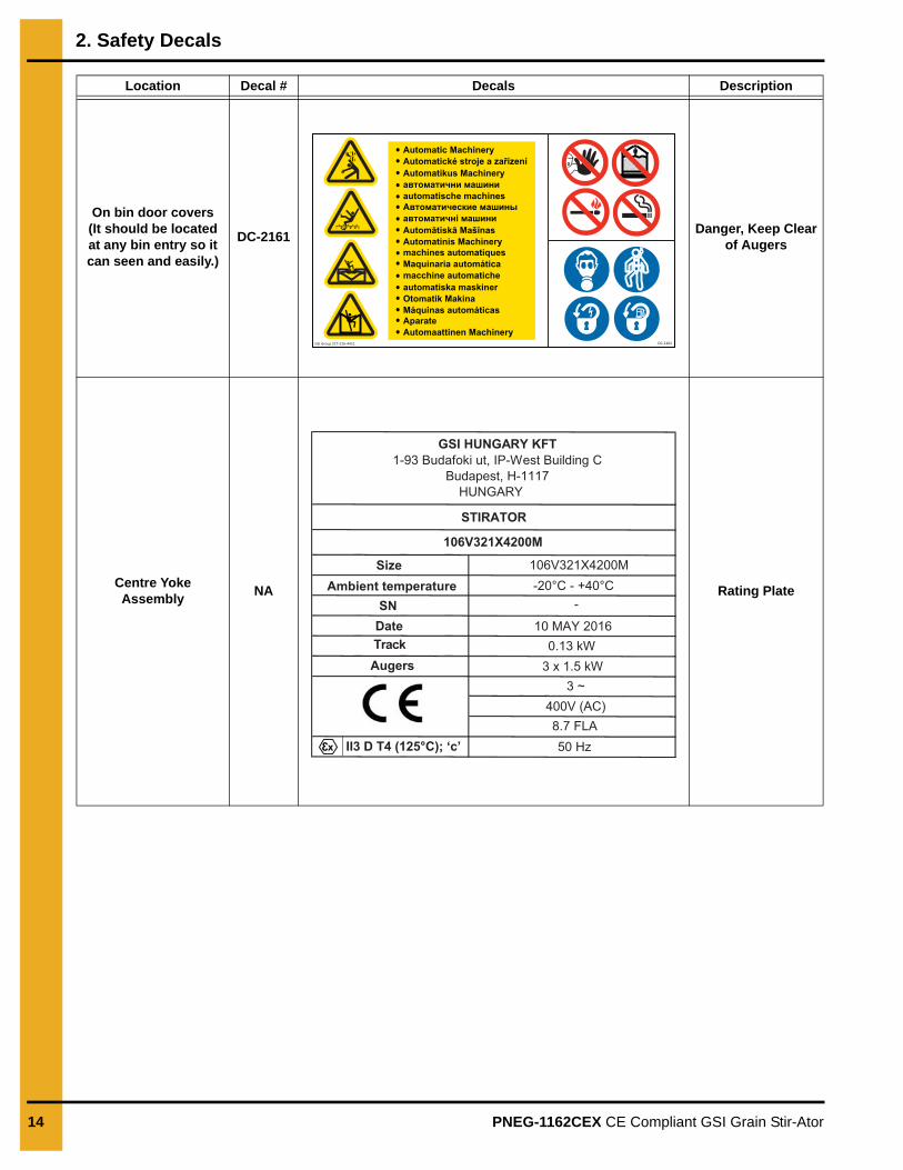
On bin door covers(It should be located at any bin entry so it can seen and easily.)
DC-2161 Danger, Keep Clear
of Augers
Centre Yoke Assembly
NA Rating Plate
Location Decal # Decals Description
DC-2161
Automatic MachineryAutomatické stroje a zařízeníAutomatikus Machineryавтоматични машиниautomatische machines
GSI Group 217-226-4421
Автоматические машиныавтоматичні машиниAutomātiskā MašīnasAutomatinis Machinerymachines automatiquesMaquinaria automáticamacchine automaticheautomatiska maskinerOtomatik MakinaMáquinas automáticasAparateAutomaattinen Machinery
SizeAmbient temperature
106V321X4200M
SNDateTrack
-20°C - +40°C
0.13 kW3 x 1.5 kW
10 MAY 2016
Augers
II3 D T4 (125°C); ‘c’
3 ~
-
400V (AC)8.7 FLA50 Hz
GSI HUNGARY KFT1-93 Budafoki ut, IP-West Building C
Budapest, H-1117 HUNGARY
STIRATOR
106V321X4200M
3x
PNEG-1162CEX CE Compliant GSI Grain Stir-Ator 15
3. Bin Loading
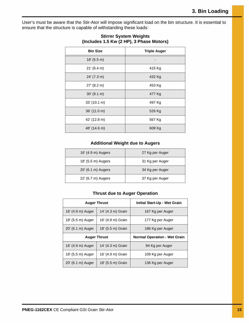
User’s must be aware that the Stir-Ator will impose significant load on the bin structure. It is essential to ensure that the structure is capable of withstanding these loads:
Stirrer System Weights (Includes 1.5 Kw (2 HP), 3 Phase Motors)
Additional Weight due to Augers
Thrust due to Auger Operation
Bin Size Triple Auger
18' (5.5 m) -
21' (6.4 m) 415 Kg
24' (7.3 m) 432 Kg
27' (8.2 m) 453 Kg
30' (9.1 m) 477 Kg
33' (10.1 m) 497 Kg
36' (11.0 m) 526 Kg
42' (12.8 m) 567 Kg
48' (14.6 m) 608 Kg
16' (4.9 m) Augers 27 Kg per Auger
18' (5.5 m) Augers 31 Kg per Auger
20' (6.1 m) Augers 34 Kg per Auger
22' (6.7 m) Augers 37 Kg per Auger
Auger Thrust Initial Start-Up - Wet Grain
16' (4.9 m) Auger 14' (4.3 m) Grain 167 Kg per Auger
18' (5.5 m) Auger 16' (4.9 m) Grain 177 Kg per Auger
20' (6.1 m) Auger 18' (5.5 m) Grain 186 Kg per Auger
Auger Thrust Normal Operation - Wet Grain
16' (4.9 m) Auger 14' (4.3 m) Grain 94 Kg per Auger
18' (5.5 m) Auger 16' (4.9 m) Grain 109 Kg per Auger
20' (6.1 m) Auger 18' (5.5 m) Grain 136 Kg per Auger
16 PNEG-1162CEX CE Compliant GSI Grain Stir-Ator
4. Installation
GSI RECOMMENDS THAT YOU REFER TO THE GRAIN BIN INSTALLATION/USAGE MANUAL, BEFORE INSTALLING THE STIR-ATOR, TO CHECK FOR ANY ADDITIONAL REQUIREMENTS FOR THE BIN TO CARRY THE STIRRING AUGER SYSTEM.
On a new bin installation, we recommend the stirrers be installed as the bin is assembled, allowing much of the work to be carried out at ground level.
Where stirrers are being retrofitted into existing bins, suitable access and lifting gear will be required inside the bin.
Track1. Track must be installed at the correct level below eaves to ensure the stirrer does not foul the roof or
other objects in the bin. See Figure 4F on Page 18 for recommended minimum dimensions.
NOTE: Internal ladders must be removed before installing stirrers.
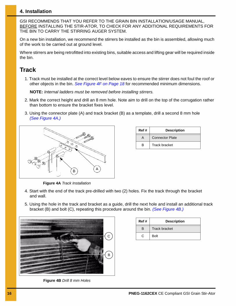
2. Mark the correct height and drill an 8 mm hole. Note aim to drill on the top of the corrugation rather than bottom to ensure the bracket fixes level.
3. Using the connector plate (A) and track bracket (B) as a template, drill a second 8 mm hole (See Figure 4A.)
Figure 4A Track Installation
4. Start with the end of the track pre-drilled with two (2) holes. Fix the track through the bracket and wall.
5. Using the hole in the track and bracket as a guide, drill the next hole and install an additional track bracket (B) and bolt (C), repeating this procedure around the bin. (See Figure 4B.)
Figure 4B Drill 8 mm Holes
Ref # Description
A Connector Plate
B Track bracket
C
B
Ref # Description
B Track bracket
C Bolt
4. Installation
PNEG-1162CEX CE Compliant GSI Grain Stir-Ator 17
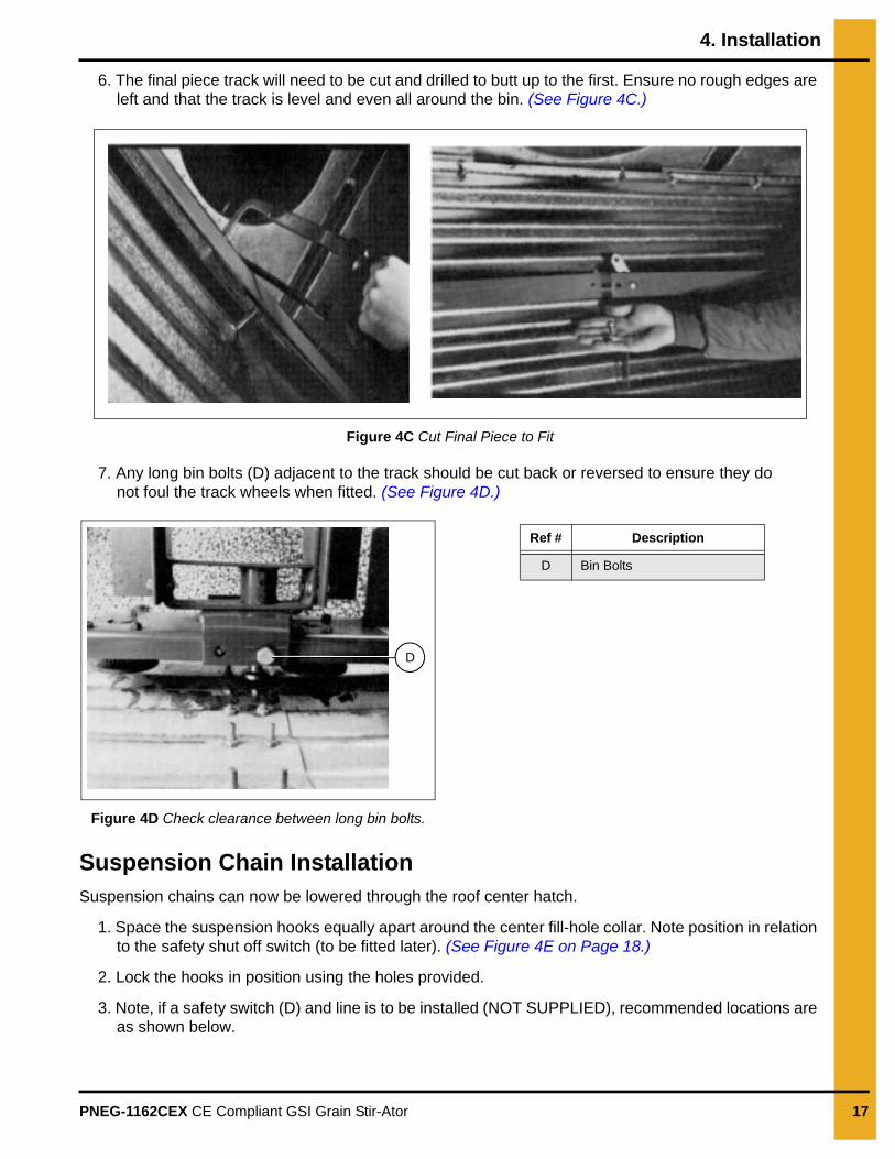
6. The final piece track will need to be cut and drilled to butt up to the first. Ensure no rough edges are left and that the track is level and even all around the bin. (See Figure 4C.)
Figure 4C Cut Final Piece to Fit
7. Any long bin bolts (D) adjacent to the track should be cut back or reversed to ensure they do not foul the track wheels when fitted. (See Figure 4D.)
Figure 4D Check clearance between long bin bolts.
Suspension Chain InstallationSuspension chains can now be lowered through the roof center hatch.
1. Space the suspension hooks equally apart around the center fill-hole collar. Note position in relation to the safety shut off switch (to be fitted later). (See Figure 4E on Page 18.)
2. Lock the hooks in position using the holes provided.
3. Note, if a safety switch (D) and line is to be installed (NOT SUPPLIED), recommended locations are as shown below.
D
Ref # Description
D Bin Bolts
4. Installation
18 PNEG-1162CEX CE Compliant GSI Grain Stir-Ator
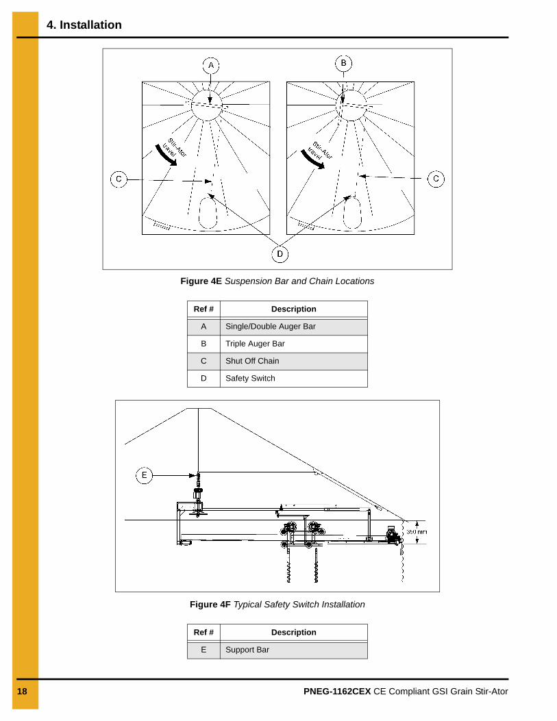
Figure 4E Suspension Bar and Chain Locations
Figure 4F Typical Safety Switch Installation
Ref # Description
A Single/Double Auger Bar
B Triple Auger Bar
C Shut Off Chain
D Safety Switch
Ref # Description
E Support Bar
4. Installation
PNEG-1162CEX CE Compliant GSI Grain Stir-Ator 19
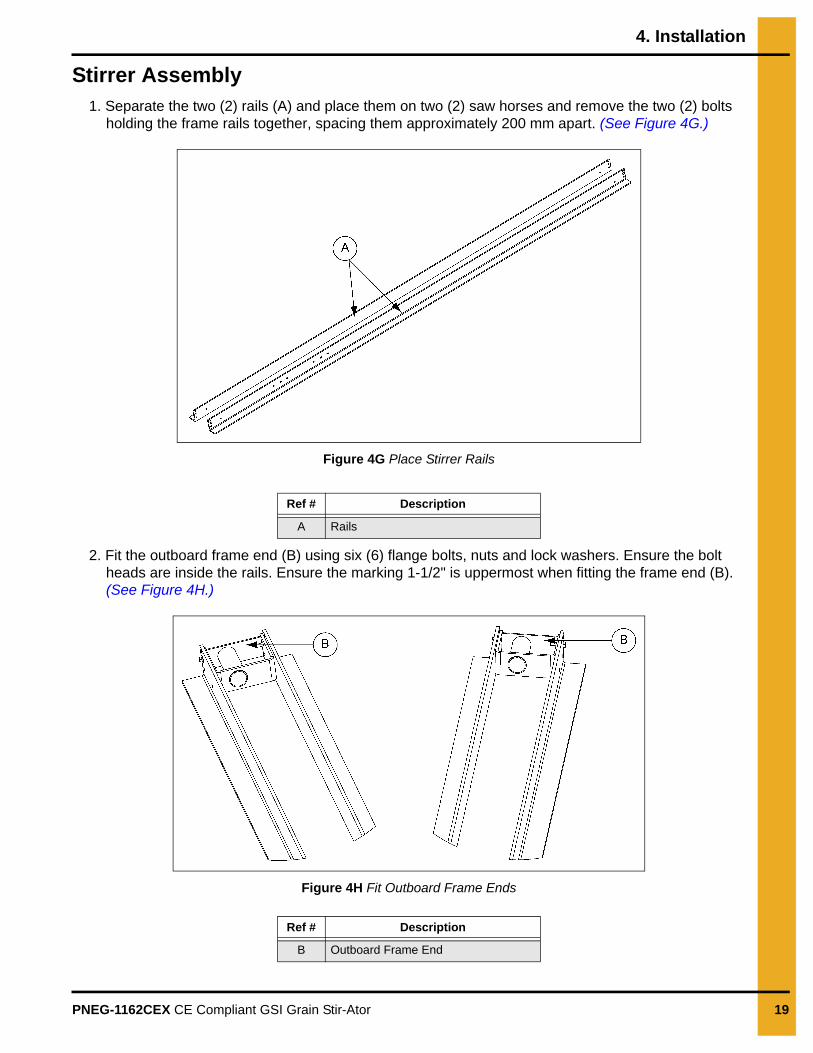
Stirrer Assembly1. Separate the two (2) rails (A) and place them on two (2) saw horses and remove the two (2) bolts
holding the frame rails together, spacing them approximately 200 mm apart. (See Figure 4G.)
Figure 4G Place Stirrer Rails
2. Fit the outboard frame end (B) using six (6) flange bolts, nuts and lock washers. Ensure the bolt heads are inside the rails. Ensure the marking 1-1/2" is uppermost when fitting the frame end (B). (See Figure 4H.)
Figure 4H Fit Outboard Frame Ends
Ref # Description
A Rails
Ref # Description
B Outboard Frame End
4. Installation
20 PNEG-1162CEX CE Compliant GSI Grain Stir-Ator
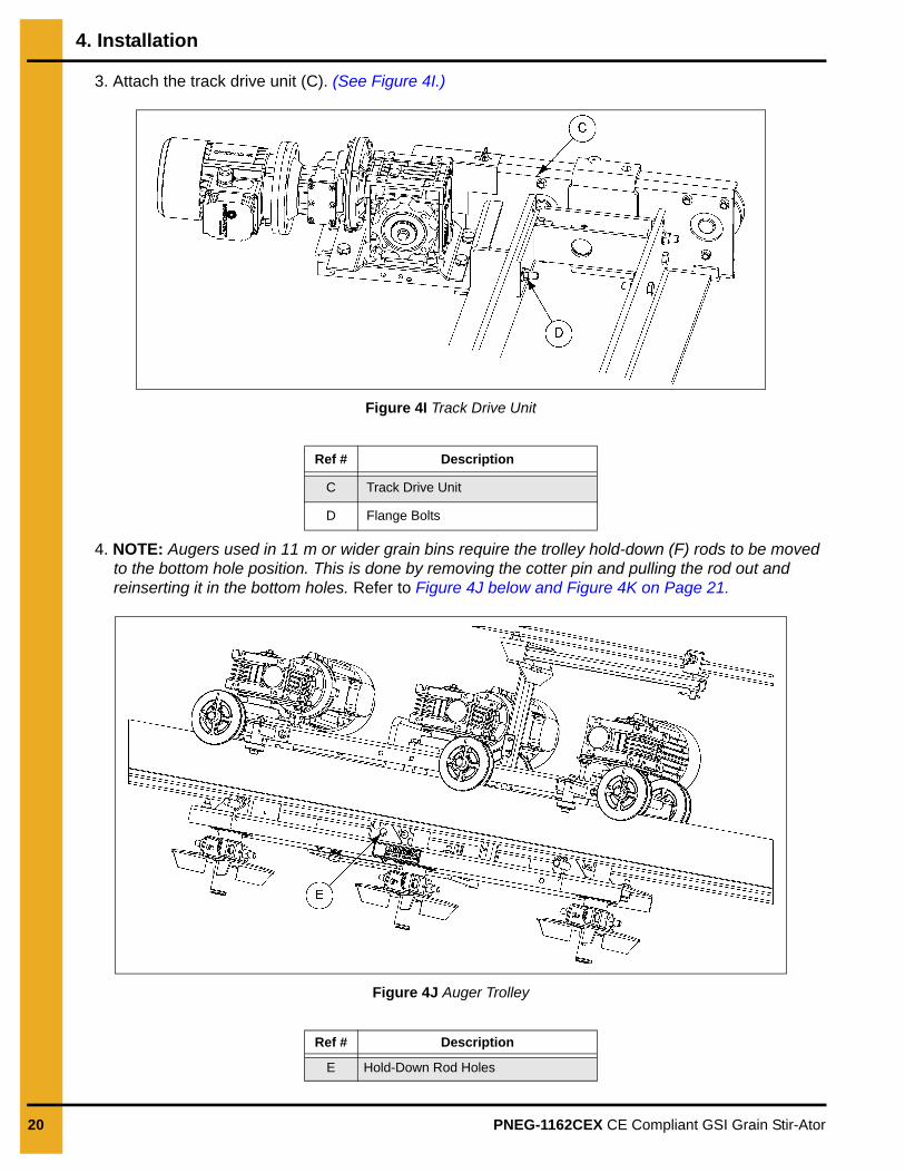
3. Attach the track drive unit (C). (See Figure 4I.)
Figure 4I Track Drive Unit
4. NOTE: Augers used in 11 m or wider grain bins require the trolley hold-down (F) rods to be moved to the bottom hole position. This is done by removing the cotter pin and pulling the rod out and reinserting it in the bottom holes. Refer to Figure 4J below and Figure 4K on Page 21.
Figure 4J Auger Trolley
Ref # Description
C Track Drive Unit
D Flange Bolts
Ref # Description
E Hold-Down Rod Holes
4. Installation
PNEG-1162CEX CE Compliant GSI Grain Stir-Ator 21
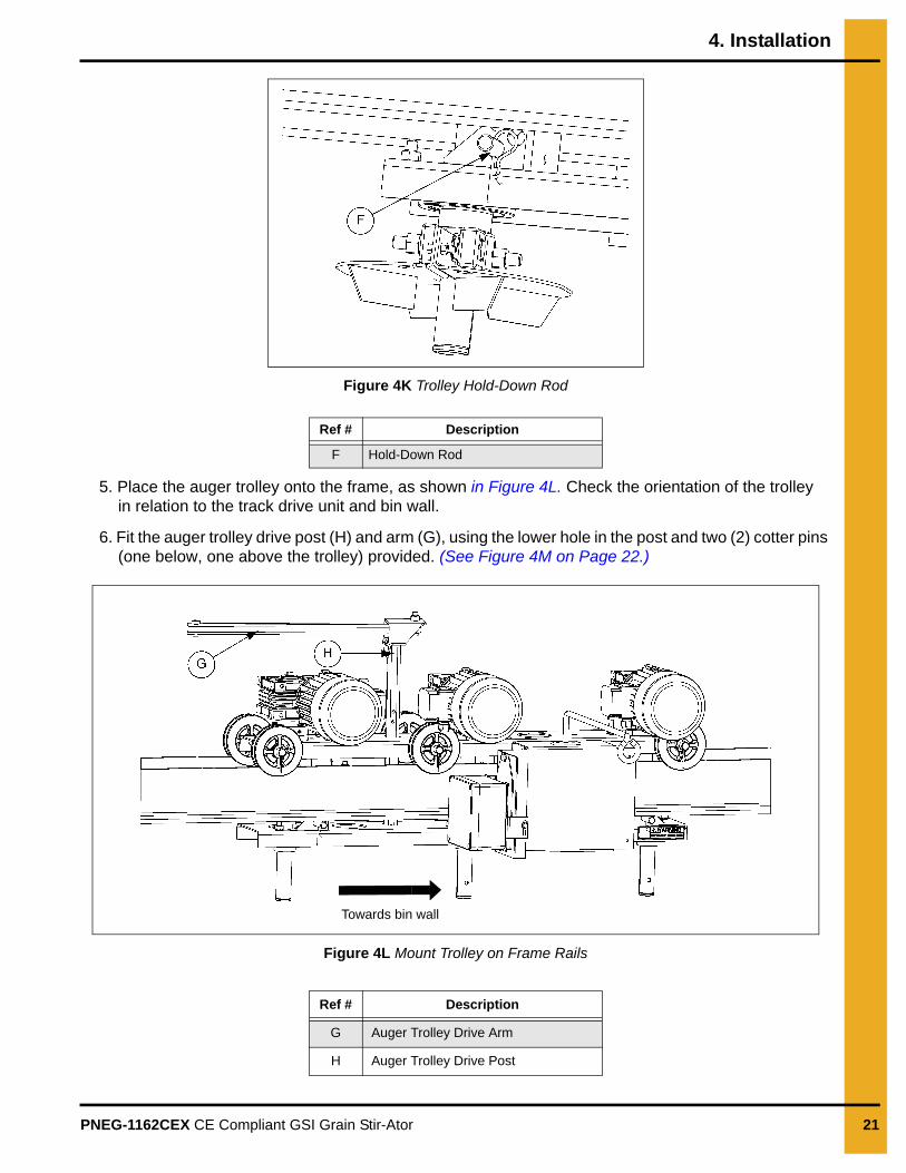
Figure 4K Trolley Hold-Down Rod
5. Place the auger trolley onto the frame, as shown in Figure 4L. Check the orientation of the trolley in relation to the track drive unit and bin wall.
6. Fit the auger trolley drive post (H) and arm (G), using the lower hole in the post and two (2) cotter pins (one below, one above the trolley) provided. (See Figure 4M on Page 22.)
Figure 4L Mount Trolley on Frame Rails
Ref # Description
F Hold-Down Rod
Ref # Description
G Auger Trolley Drive Arm
H Auger Trolley Drive Post
Towards bin wall
4. Installation
22 PNEG-1162CEX CE Compliant GSI Grain Stir-Ator
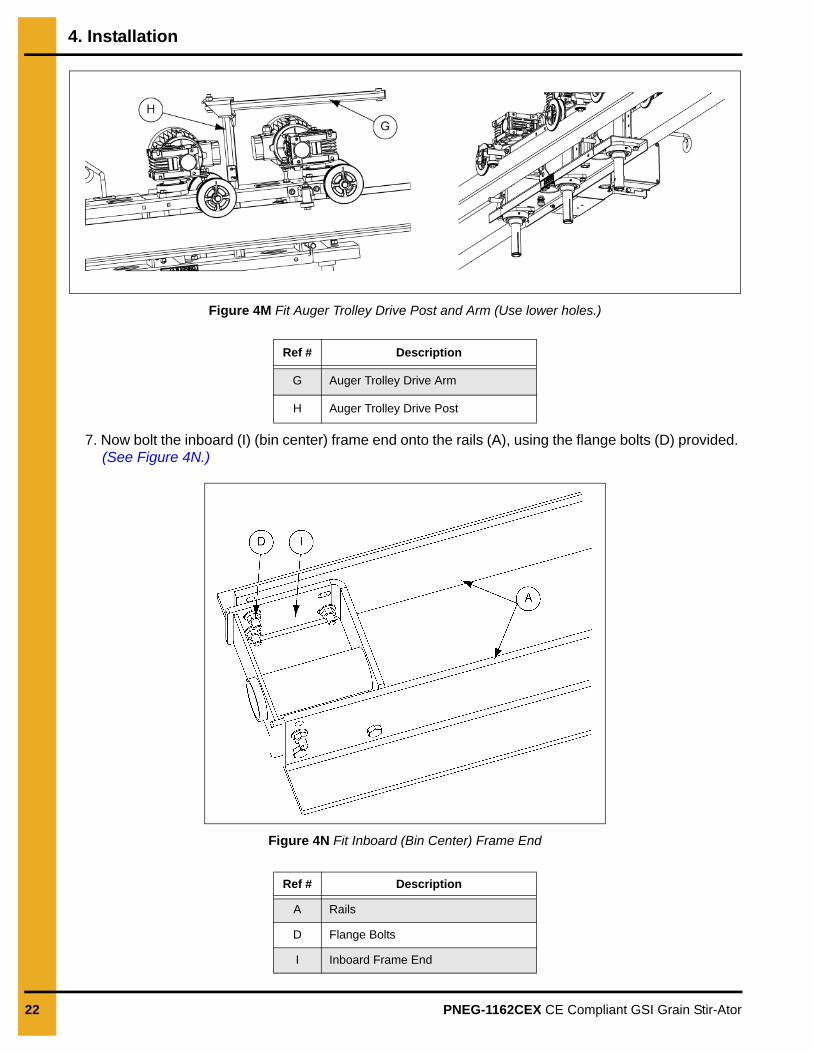
Figure 4M Fit Auger Trolley Drive Post and Arm (Use lower holes.)
7. Now bolt the inboard (I) (bin center) frame end onto the rails (A), using the flange bolts (D) provided. (See Figure 4N.)
Figure 4N Fit Inboard (Bin Center) Frame End
Ref # Description
G Auger Trolley Drive Arm
H Auger Trolley Drive Post
Ref # Description
A Rails
D Flange Bolts
I Inboard Frame End
4. Installation
PNEG-1162CEX CE Compliant GSI Grain Stir-Ator 23
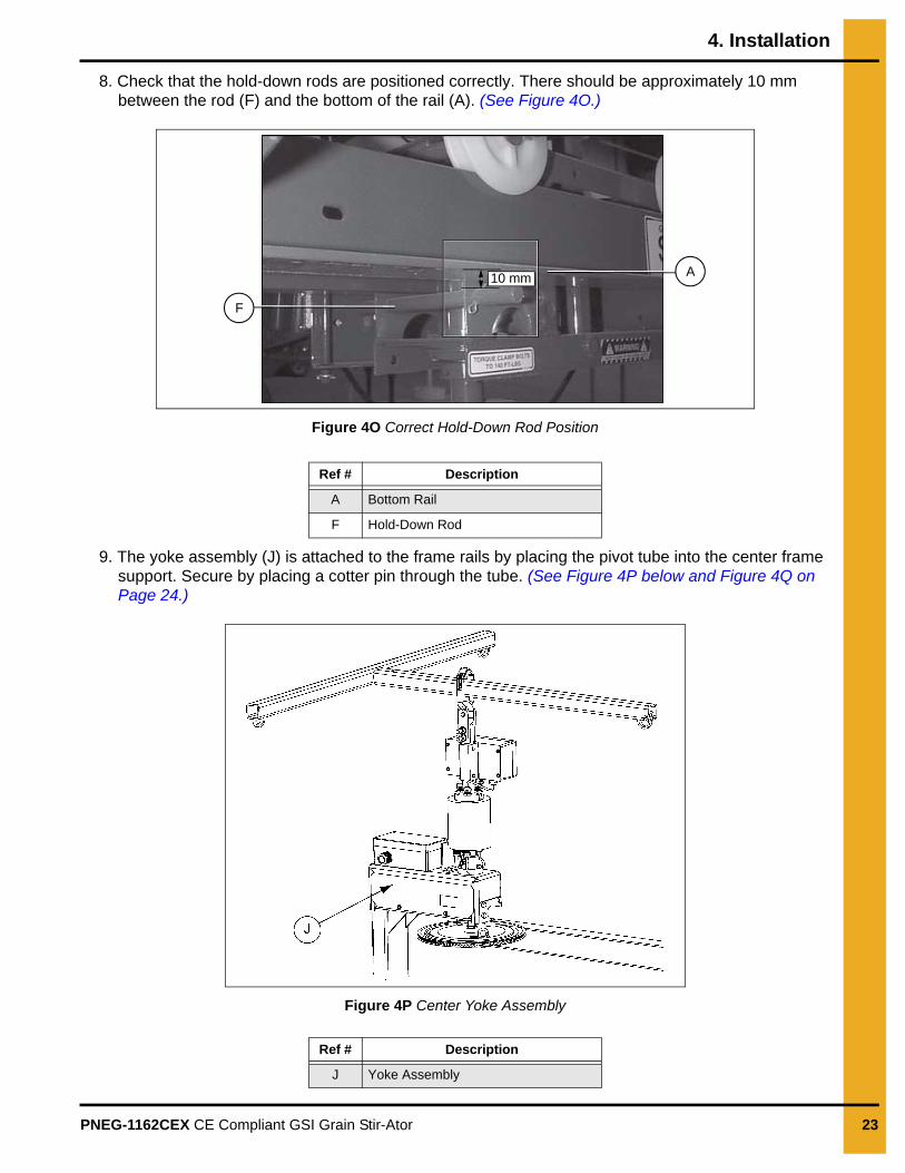
8. Check that the hold-down rods are positioned correctly. There should be approximately 10 mm between the rod (F) and the bottom of the rail (A). (See Figure 4O.)
Figure 4O Correct Hold-Down Rod Position
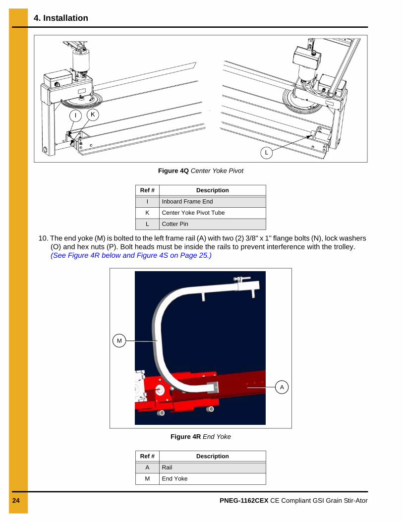
9. The yoke assembly (J) is attached to the frame rails by placing the pivot tube into the center frame support. Secure by placing a cotter pin through the tube. (See Figure 4P below and Figure 4Q on Page 24.)
Figure 4P Center Yoke Assembly
Ref # Description
A Bottom Rail
F Hold-Down Rod
Ref # Description
J Yoke Assembly
10 mm A
F
4. Installation
24 PNEG-1162CEX CE Compliant GSI Grain Stir-Ator
Figure 4Q Center Yoke Pivot
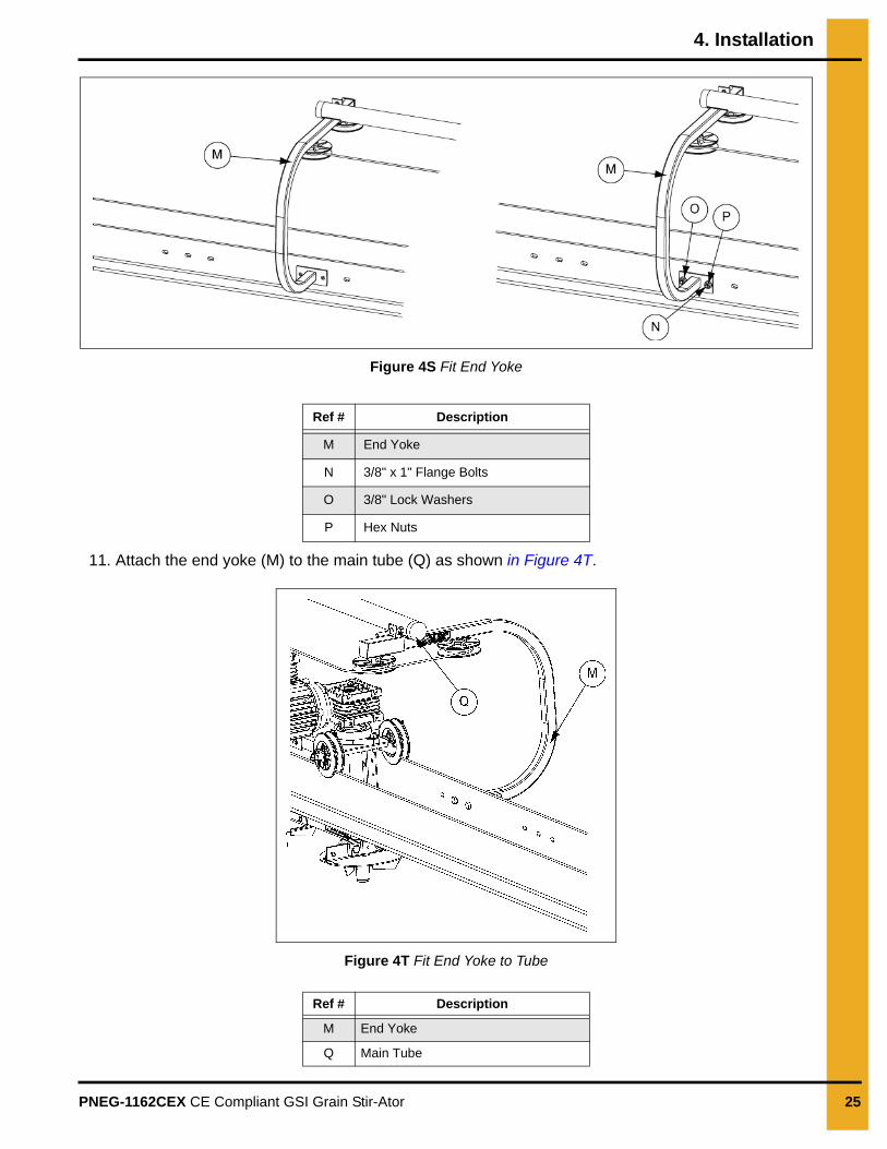
10. The end yoke (M) is bolted to the left frame rail (A) with two (2) 3/8" x 1" flange bolts (N), lock washers (O) and hex nuts (P). Bolt heads must be inside the rails to prevent interference with the trolley. (See Figure 4R below and Figure 4S on Page 25.)
Figure 4R End Yoke
Ref # Description
I Inboard Frame End
K Center Yoke Pivot Tube
L Cotter Pin
Ref # Description
A Rail
M End Yoke
A
M
4. Installation
PNEG-1162CEX CE Compliant GSI Grain Stir-Ator 25
Figure 4S Fit End Yoke
11. Attach the end yoke (M) to the main tube (Q) as shown in Figure 4T.
Figure 4T Fit End Yoke to Tube
Ref # Description
M End Yoke
N 3/8" x 1" Flange Bolts
O 3/8" Lock Washers
P Hex Nuts
Ref # Description
M End Yoke
Q Main Tube
4. Installation
26 PNEG-1162CEX CE Compliant GSI Grain Stir-Ator
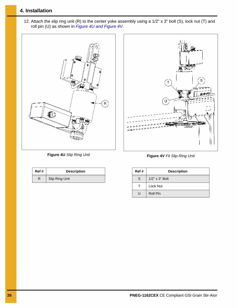
12. Attach the slip ring unit (R) to the center yoke assembly using a 1/2" x 3" bolt (S), lock nut (T) and roll pin (U) as shown in Figure 4U and Figure 4V.
Figure 4U Slip Ring Unit Figure 4V Fit Slip Ring Unit
Ref # Description
R Slip Ring Unit
Ref # Description
S 1/2" x 3" Bolt
T Lock Nut
U Roll Pin
4. Installation
PNEG-1162CEX CE Compliant GSI Grain Stir-Ator 27
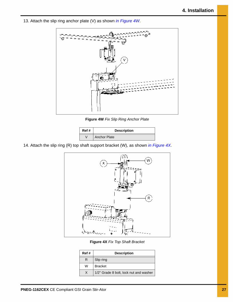
13. Attach the slip ring anchor plate (V) as shown in Figure 4W.
Figure 4W Fix Slip Ring Anchor Plate
14. Attach the slip ring (R) top shaft support bracket (W), as shown in Figure 4X.
Figure 4X Fix Top Shaft Bracket
Ref # Description
V Anchor Plate
Ref # Description
R Slip ring
W Bracket
X 1/2" Grade 8 bolt, lock nut and washer
4. Installation
28 PNEG-1162CEX CE Compliant GSI Grain Stir-Ator
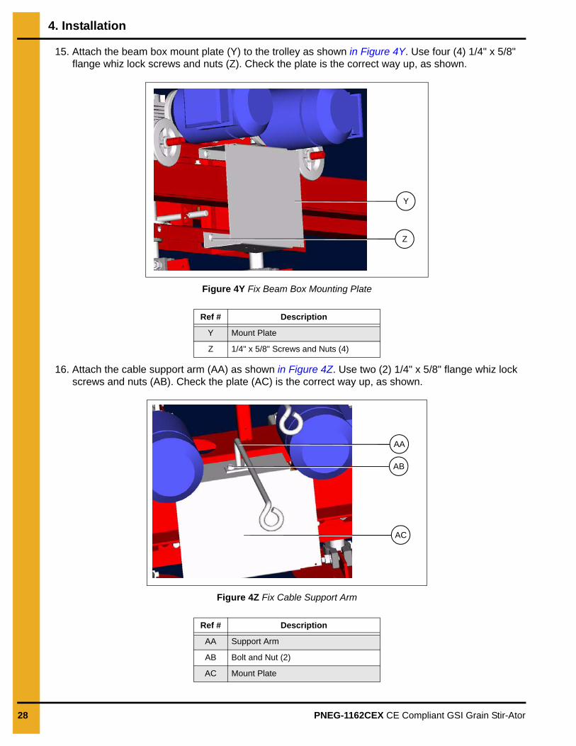
15. Attach the beam box mount plate (Y) to the trolley as shown in Figure 4Y. Use four (4) 1/4" x 5/8" flange whiz lock screws and nuts (Z). Check the plate is the correct way up, as shown.
Figure 4Y Fix Beam Box Mounting Plate
16. Attach the cable support arm (AA) as shown in Figure 4Z. Use two (2) 1/4" x 5/8" flange whiz lock screws and nuts (AB). Check the plate (AC) is the correct way up, as shown.
Figure 4Z Fix Cable Support Arm
Ref # Description
Y Mount Plate
Z 1/4" x 5/8" Screws and Nuts (4)
Ref # Description
AA Support Arm
AB Bolt and Nut (2)
AC Mount Plate
Y
Z
AA
AB
AC
4. Installation
PNEG-1162CEX CE Compliant GSI Grain Stir-Ator 29
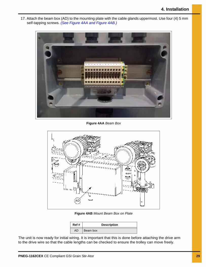
17. Attach the beam box (AD) to the mounting plate with the cable glands uppermost. Use four (4) 5 mm self-tapping screws. (See Figure 4AA and Figure 4AB.)
Figure 4AA Beam Box
Figure 4AB Mount Beam Box on Plate
The unit is now ready for initial wiring. It is important that this is done before attaching the drive arm to the drive wire so that the cable lengths can be checked to ensure the trolley can move freely.
Ref # Description
AD Beam box
4. Installation
30 PNEG-1162CEX CE Compliant GSI Grain Stir-Ator
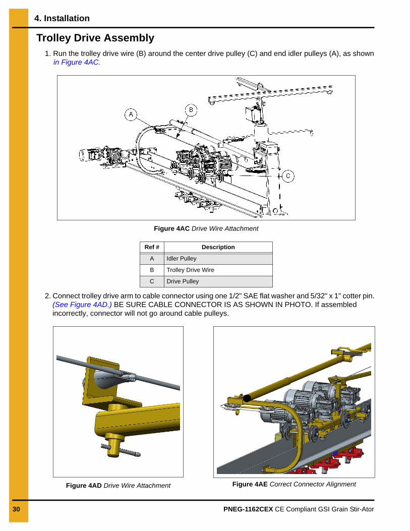
Trolley Drive Assembly1. Run the trolley drive wire (B) around the center drive pulley (C) and end idler pulleys (A), as shown
in Figure 4AC.
Figure 4AC Drive Wire Attachment
2. Connect trolley drive arm to cable connector using one 1/2" SAE flat washer and 5/32" x 1" cotter pin. (See Figure 4AD.) BE SURE CABLE CONNECTOR IS AS SHOWN IN PHOTO. If assembled incorrectly, connector will not go around cable pulleys.
Figure 4AD Drive Wire Attachment Figure 4AE Correct Connector Alignment
Ref # Description
A Idler Pulley
B Trolley Drive Wire
C Drive Pulley
4. Installation
PNEG-1162CEX CE Compliant GSI Grain Stir-Ator 31
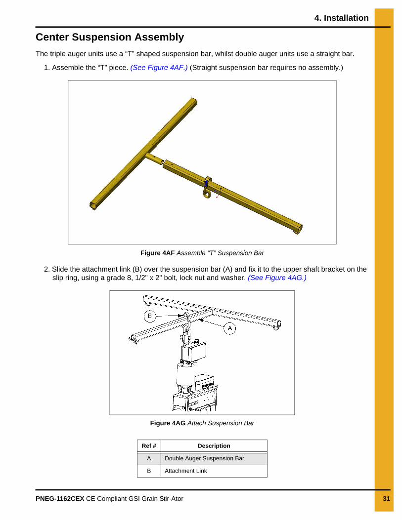
Center Suspension Assembly
The triple auger units use a “T” shaped suspension bar, whilst double auger units use a straight bar.
1. Assemble the “T” piece. (See Figure 4AF.) (Straight suspension bar requires no assembly.)
Figure 4AF Assemble “T” Suspension Bar
2. Slide the attachment link (B) over the suspension bar (A) and fix it to the upper shaft bracket on the slip ring, using a grade 8, 1/2" x 2" bolt, lock nut and washer. (See Figure 4AG.)
Figure 4AG Attach Suspension Bar
Ref # Description
A Double Auger Suspension Bar
B Attachment Link
4. Installation
32 PNEG-1162CEX CE Compliant GSI Grain Stir-Ator
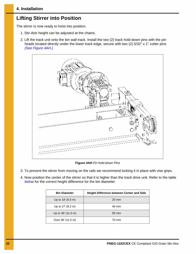
Lifting Stirrer into Position
The stirrer is now ready to hoist into position.
1. Stir-Ator height can be adjusted at the chains.
2. Lift the track unit onto the bin wall track. Install the two (2) track hold-down pins with the pin heads located directly under the lower track edge, secure with two (2) 5/32" x 1" cotter pins. (See Figure 4AH.)
Figure 4AH Fit Hold-down Pins
3. To prevent the stirrer from moving on the rails we recommend locking it in place with vise grips.
4. Now position the center of the stirrer so that it is higher than the track drive unit. Refer to the table below for the correct height difference for the bin diameter.
Bin Diameter Height Difference between Center and Side
Up to 18' (5.5 m) 25 mm
Up to 27' (8.2 m) 40 mm
Up to 36' (11.0 m) 55 mm
Over 36' (11.0 m) 70 mm

4. Installation
PNEG-1162CEX CE Compliant GSI Grain Stir-Ator 33
Connection to Power Supply
Stir Guard
1. Stir guard is a safety timer system designed to shut off the augers in the event that the track unit is unable to move the Stir-Ator around the bin. This prevents damage to the grain.
Install Augers
1. The stirrer auger may need to be cut to length so that it hangs at least 75 mm above the highest point on the floor of the grain bin.
2. In a bin with no sweep auger and just a flat floor, the highest point must be taken as the floor immediately adjacent to the bin wall.
3. If the bin is fitted with any sweep or floor augers, auger must be measured from the highest part of the floor auger.
4. To measure the auger rod length, position the trolley directly above the highest point, insert a tape into the auger stub shaft and measure to the highest point. Remove 75 mm from this height to get the required auger length.
5. Measure the length on the auger rod and cut to length. ONLY CUT FROM THE BOTTOM OF THE AUGER. NEVER FROM THE TOP.
6. Use a small grinder to remove any burrs from the cut edge.
7. To prevent the auger flight from coming away at the cut end the flight should be welded to the rod using 20 mm tack welds, starting at the end of the flight and rod and in 2 further positions within the first pitch of flight. (See Figure 4AI on Page 34.)
It is essential that the Stir-Ator is supplied via a safety isolator located at the eaves hatch of the bin. This must be rated to IP 65 minimum and have a current rating no less than 32 amps. The switch must also be lockable.
Once the auger is installed into a grain bin, the bin becomes a hazardous environment. No-one must ever be in the bin when the auger is operating.
GSI recommends the installation of safety switches on the personnel door so that whenever the door is opened all equipment stops automatically and cannot be restarted without the door first being closed and the operator restarting at the main control panel.
GSI recommends the installation of suitable emergency stops to stop all equipment within the bin in the event of an emergency.
This is the responsibility of the installer and a requirement under the CE directives to which this installation must comply. Failure to do so can endanger life and will invalidate any warranties and guarantees.
4. Installation
34 PNEG-1162CEX CE Compliant GSI Grain Stir-Ator
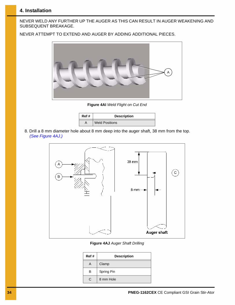
NEVER WELD ANY FURTHER UP THE AUGER AS THIS CAN RESULT IN AUGER WEAKENING AND SUBSEQUENT BREAKAGE.
NEVER ATTEMPT TO EXTEND AND AUGER BY ADDING ADDITIONAL PIECES.
Figure 4AI Weld Flight on Cut End
8. Drill a 8 mm diameter hole about 8 mm deep into the auger shaft, 38 mm from the top. (See Figure 4AJ.)
Figure 4AJ Auger Shaft Drilling
Ref # Description
A Weld Positions
Ref # Description
A Clamp
B Spring Pin
C 8 mm Hole
A
4. Installation
PNEG-1162CEX CE Compliant GSI Grain Stir-Ator 35
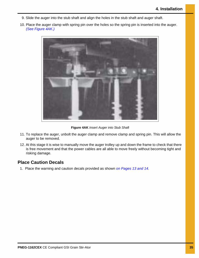
9. Slide the auger into the stub shaft and align the holes in the stub shaft and auger shaft.
10. Place the auger clamp with spring pin over the holes so the spring pin is inserted into the auger. (See Figure 4AK.)
Figure 4AK Insert Auger into Stub Shaft
11. To replace the auger, unbolt the auger clamp and remove clamp and spring pin. This will allow the auger to be removed.
12. At this stage it is wise to manually move the auger trolley up and down the frame to check that there is free movement and that the power cables are all able to move freely without becoming tight and risking damage.
Place Caution Decals1. Place the warning and caution decals provided as shown on Pages 13 and 14.
36 PNEG-1162CEX CE Compliant GSI Grain Stir-Ator
5. Electrical Installation
ATEX Rating
The Stir-Ator is rated for use in a hazardous dusty location, in accordance with ATEX zone 22D. All electrical equipment, enclosures, conduits and cable glands used inside the silo or on the Stir-Ator must comply to the same, or better standard.
Control System
The Stir-Ator will require a suitable control system, designed and tested in accordance with EN60204. Recommended wiring diagrams are given below on Pages 39-46 and include the following required features:
1. Door interlocking and emergency stopping safety circuit.
a. This must be to a minimum performance level (PL) ‘c’ in accordance with EN13849.
b. Door switches, to SIL3, are required for each personnel entry to the silo.
c. Emergency stop switches are required at the control position and main silo entrance as a minimum. Further may be added in accordance with a site risk assessment.
2. Main power isolation switch is required at the control panel.
3. A service disconnect switch is required at the eaves hatch to provide complete disconnection of the power to the stirrer for purposes of servicing.
4. Motor overload protection.
5. Short circuit protection.
6. Earth leakage/residual current protection.
7. Low impedance protective earth (PE) circuit to each electrical component and conductive surface.
In addition the following features are recommended:
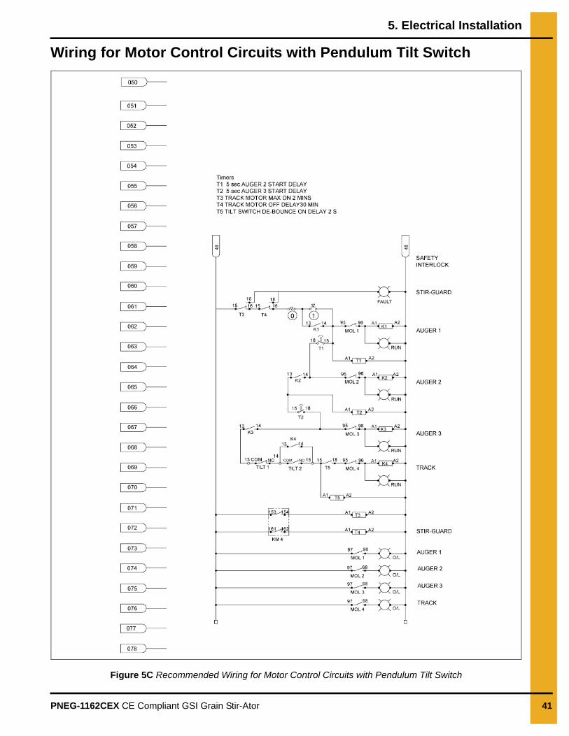
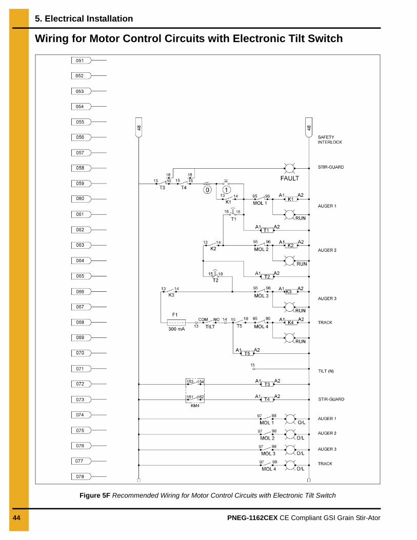
1. Sequential auger starting. A time delay of approximately 5 seconds between starting auger 1, 2 and 3, to reduce auger beam impact and starting currents is recommended.
2. ‘Stir-guard’. Maximum run and maximum stop timers are recommended for the track motor, to shut the system down in the event that the stirrer tracking system is mal-functioning. Maximum run time recommended is 2 minutes. Maximum stop time recommended is 30 minutes. In the event that these times are exceeded, the Stir-Ator should be stopped.
3. Tilt switch ‘de-bouncing’ timer. A 2 second on-delay timer is recommended to reduce the risk of contact bounce on the Stir-Ator tilt switch.
Electrical installation must be carried out by a suitable qualified electrical installer, in accordance with EU Directives, regulations and local laws.
5. Electrical Installation
PNEG-1162CEX CE Compliant GSI Grain Stir-Ator 37
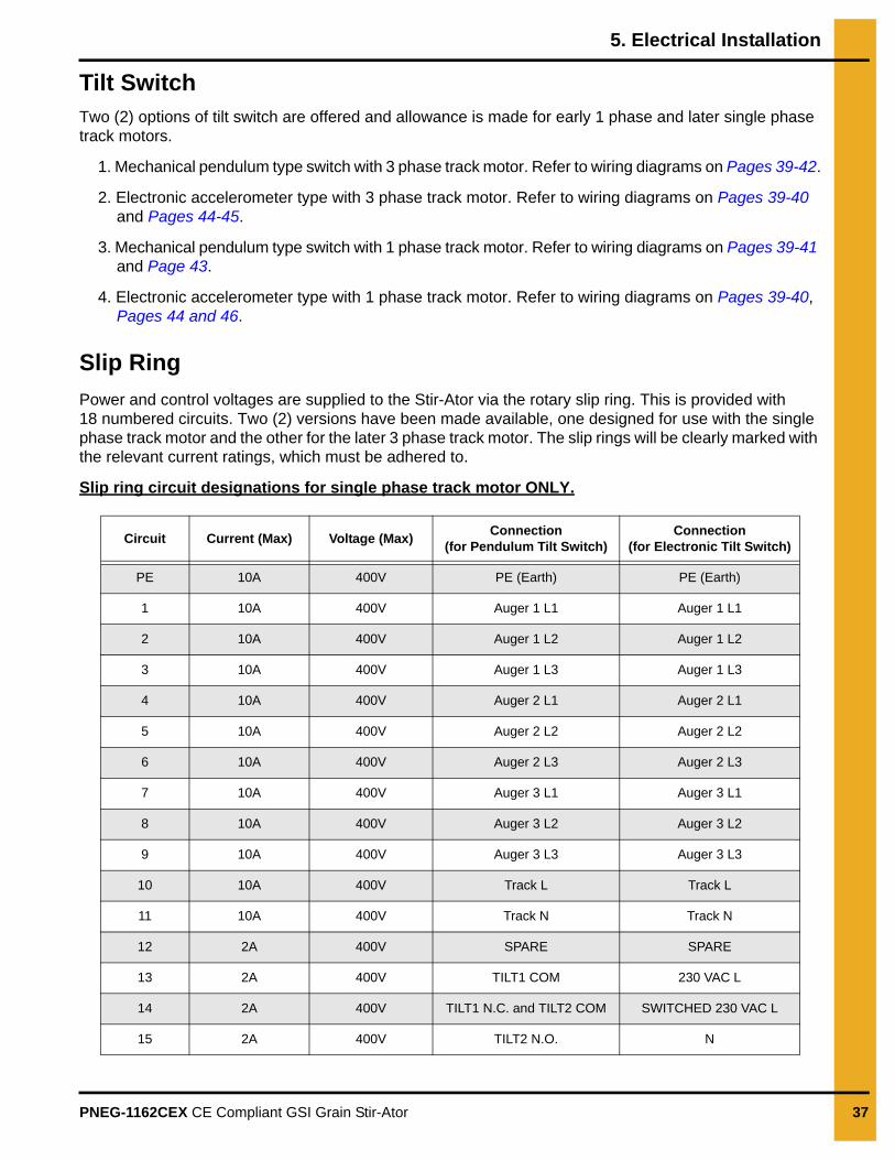
Tilt SwitchTwo (2) options of tilt switch are offered and allowance is made for early 1 phase and later single phase track motors.
1. Mechanical pendulum type switch with 3 phase track motor. Refer to wiring diagrams on Pages 39-42.
2. Electronic accelerometer type with 3 phase track motor. Refer to wiring diagrams on Pages 39-40 and Pages 44-45.
3. Mechanical pendulum type switch with 1 phase track motor. Refer to wiring diagrams on Pages 39-41 and Page 43.
4. Electronic accelerometer type with 1 phase track motor. Refer to wiring diagrams on Pages 39-40, Pages 44 and 46.
Slip Ring
Power and control voltages are supplied to the Stir-Ator via the rotary slip ring. This is provided with 18 numbered circuits. Two (2) versions have been made available, one designed for use with the single phase track motor and the other for the later 3 phase track motor. The slip rings will be clearly marked with the relevant current ratings, which must be adhered to.
Slip ring circuit designations for single phase track motor ONLY.
Circuit Current (Max) Voltage (Max)Connection
(for Pendulum Tilt Switch)Connection
(for Electronic Tilt Switch)
PE 10A 400V PE (Earth) PE (Earth)
1 10A 400V Auger 1 L1 Auger 1 L1
2 10A 400V Auger 1 L2 Auger 1 L2
3 10A 400V Auger 1 L3 Auger 1 L3
4 10A 400V Auger 2 L1 Auger 2 L1
5 10A 400V Auger 2 L2 Auger 2 L2
6 10A 400V Auger 2 L3 Auger 2 L3
7 10A 400V Auger 3 L1 Auger 3 L1
8 10A 400V Auger 3 L2 Auger 3 L2
9 10A 400V Auger 3 L3 Auger 3 L3
10 10A 400V Track L Track L
11 10A 400V Track N Track N
12 2A 400V SPARE SPARE
13 2A 400V TILT1 COM 230 VAC L
14 2A 400V TILT1 N.C. and TILT2 COM SWITCHED 230 VAC L
15 2A 400V TILT2 N.O. N
5. Electrical Installation
38 PNEG-1162CEX CE Compliant GSI Grain Stir-Ator
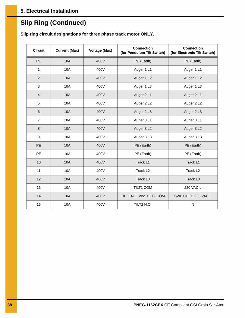
Slip Ring (Continued)
Slip ring circuit designations for three phase track motor ONLY.
Circuit Current (Max) Voltage (Max)Connection
(for Pendulum Tilt Switch)Connection
(for Electronic Tilt Switch)
PE 10A 400V PE (Earth) PE (Earth)
1 10A 400V Auger 1 L1 Auger 1 L1
2 10A 400V Auger 1 L2 Auger 1 L2
3 10A 400V Auger 1 L3 Auger 1 L3
4 10A 400V Auger 2 L1 Auger 2 L1
5 10A 400V Auger 2 L2 Auger 2 L2
6 10A 400V Auger 2 L3 Auger 2 L3
7 10A 400V Auger 3 L1 Auger 3 L1
8 10A 400V Auger 3 L2 Auger 3 L2
9 10A 400V Auger 3 L3 Auger 3 L3
PE 10A 400V PE (Earth) PE (Earth)
PE 10A 400V PE (Earth) PE (Earth)
10 10A 400V Track L1 Track L1
11 10A 400V Track L2 Track L2
12 10A 400V Track L3 Track L3
13 10A 400V TILT1 COM 230 VAC L
14 10A 400V TILT1 N.C. and TILT2 COM SWITCHED 230 VAC L
15 10A 400V TILT2 N.O. N
5. Electrical Installation
PNEG-1162CEX CE Compliant GSI Grain Stir-Ator 39
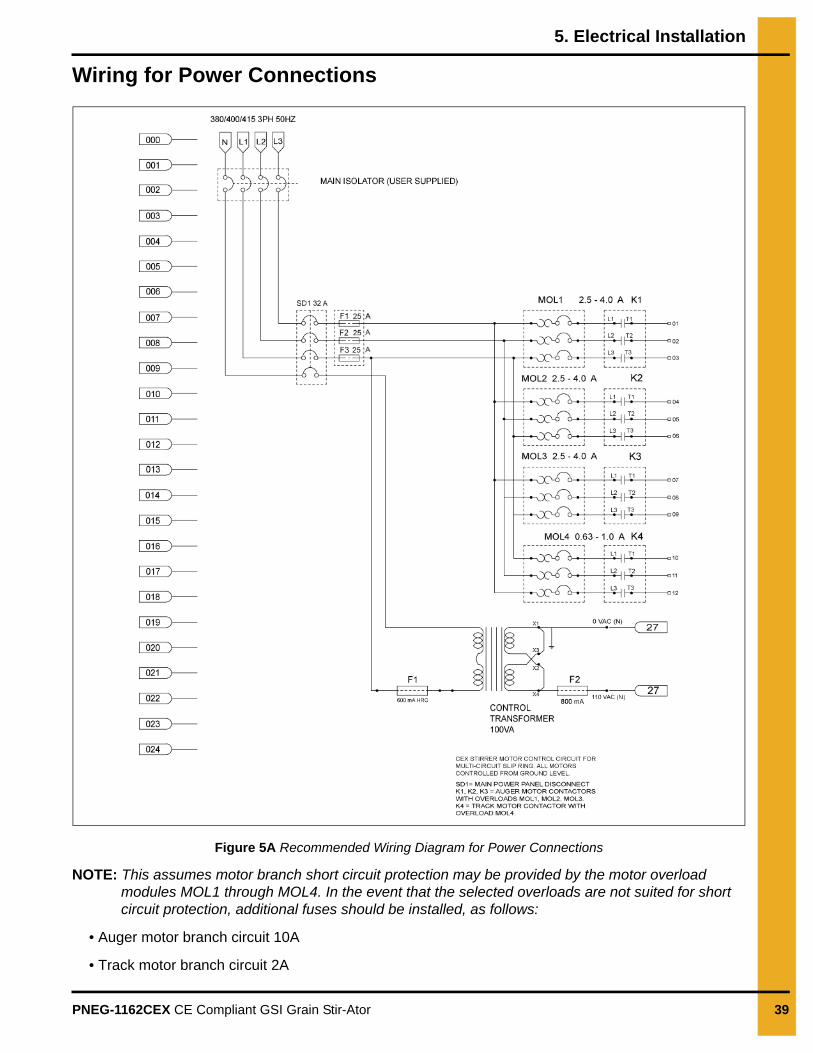
Wiring for Power Connections
Figure 5A Recommended Wiring Diagram for Power Connections
NOTE: This assumes motor branch short circuit protection may be provided by the motor overload modules MOL1 through MOL4. In the event that the selected overloads are not suited for short circuit protection, additional fuses should be installed, as follows:
• Auger motor branch circuit 10A
• Track motor branch circuit 2A
5. Electrical Installation
40 PNEG-1162CEX CE Compliant GSI Grain Stir-Ator
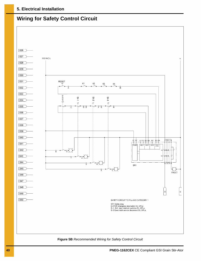
Wiring for Safety Control Circuit
Figure 5B Recommended Wiring for Safety Control Circuit
5. Electrical Installation
PNEG-1162CEX CE Compliant GSI Grain Stir-Ator 41
Wiring for Motor Control Circuits with Pendulum Tilt Switch
Figure 5C Recommended Wiring for Motor Control Circuits with Pendulum Tilt Switch
5. Electrical Installation
42 PNEG-1162CEX CE Compliant GSI Grain Stir-Ator
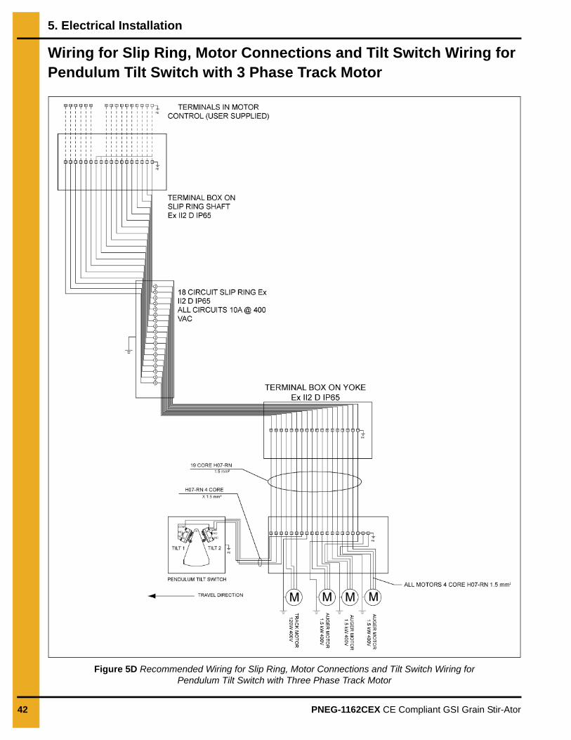
Wiring for Slip Ring, Motor Connections and Tilt Switch Wiring for Pendulum Tilt Switch with 3 Phase Track Motor
Figure 5D Recommended Wiring for Slip Ring, Motor Connections and Tilt Switch Wiring for Pendulum Tilt Switch with Three Phase Track Motor
5. Electrical Installation
PNEG-1162CEX CE Compliant GSI Grain Stir-Ator 43
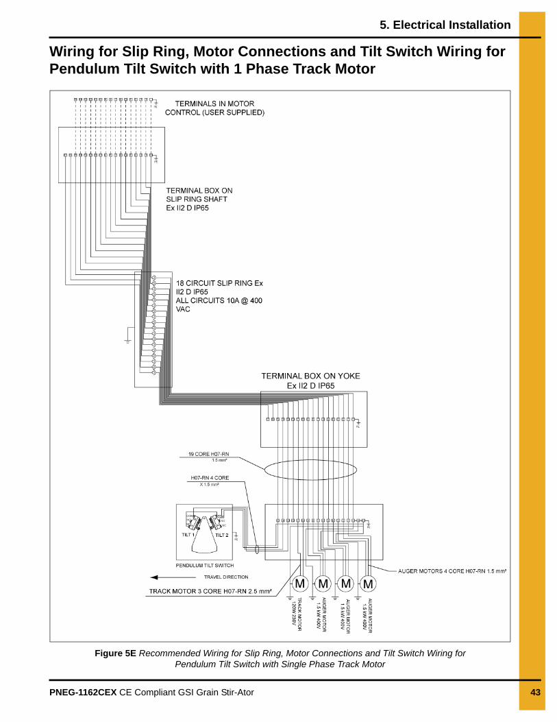
Wiring for Slip Ring, Motor Connections and Tilt Switch Wiring for Pendulum Tilt Switch with 1 Phase Track Motor
Figure 5E Recommended Wiring for Slip Ring, Motor Connections and Tilt Switch Wiring for Pendulum Tilt Switch with Single Phase Track Motor
5. Electrical Installation
44 PNEG-1162CEX CE Compliant GSI Grain Stir-Ator
Wiring for Motor Control Circuits with Electronic Tilt Switch
Figure 5F Recommended Wiring for Motor Control Circuits with Electronic Tilt Switch
5. Electrical Installation
PNEG-1162CEX CE Compliant GSI Grain Stir-Ator 45
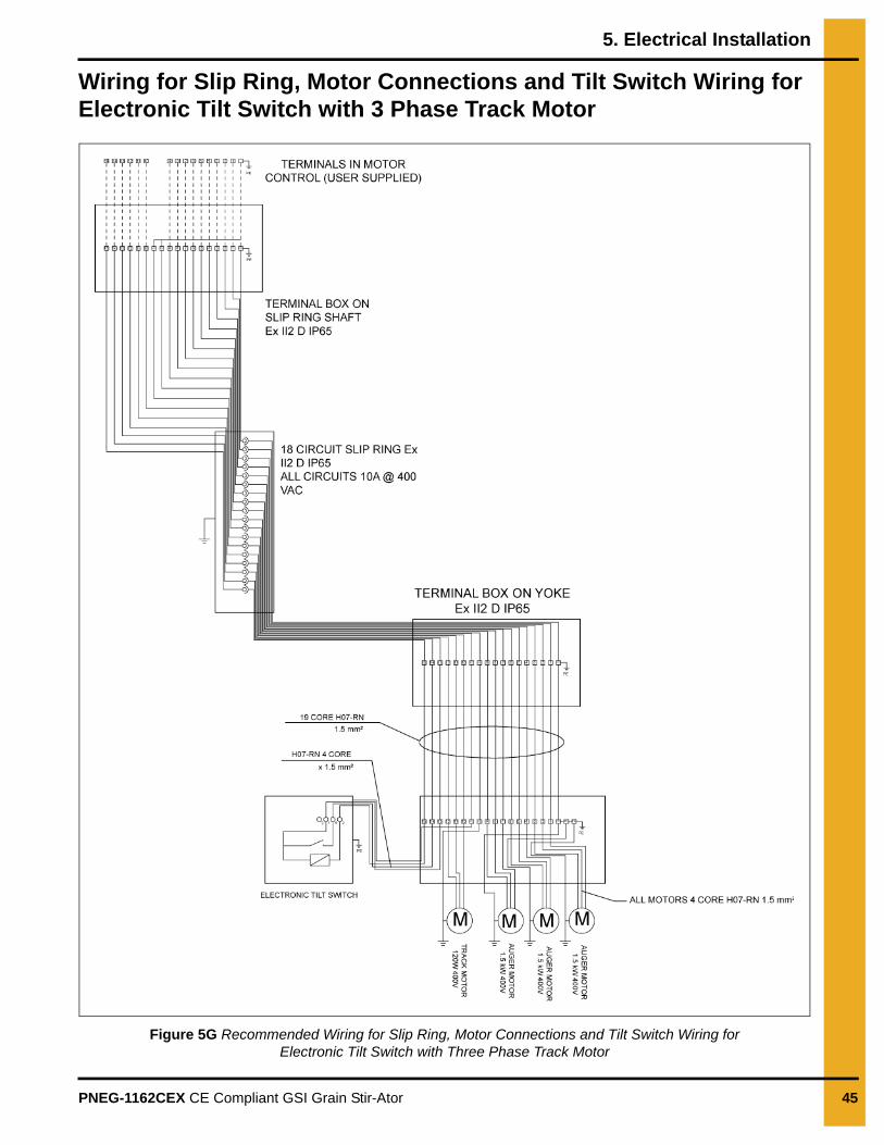
Wiring for Slip Ring, Motor Connections and Tilt Switch Wiring for Electronic Tilt Switch with 3 Phase Track Motor
Figure 5G Recommended Wiring for Slip Ring, Motor Connections and Tilt Switch Wiring for Electronic Tilt Switch with Three Phase Track Motor
5. Electrical Installation
46 PNEG-1162CEX CE Compliant GSI Grain Stir-Ator
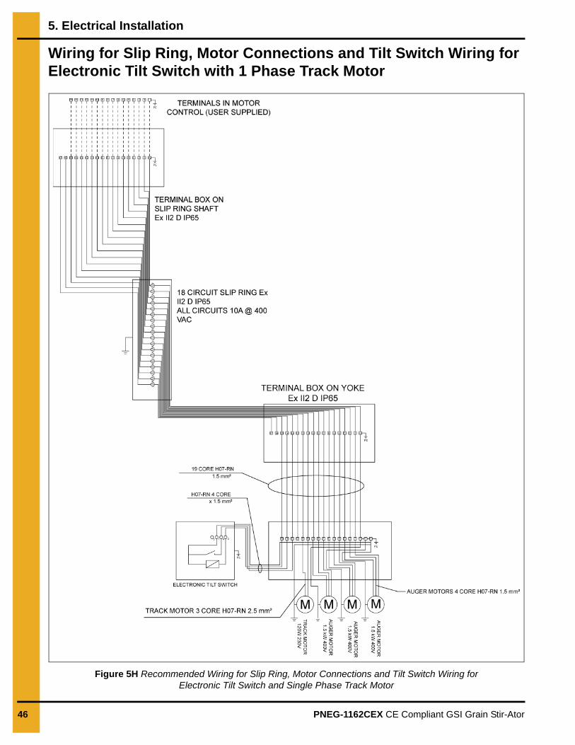
Wiring for Slip Ring, Motor Connections and Tilt Switch Wiring for Electronic Tilt Switch with 1 Phase Track Motor
Figure 5H Recommended Wiring for Slip Ring, Motor Connections and Tilt Switch Wiring for Electronic Tilt Switch and Single Phase Track Motor
5. Electrical Installation
PNEG-1162CEX CE Compliant GSI Grain Stir-Ator 47
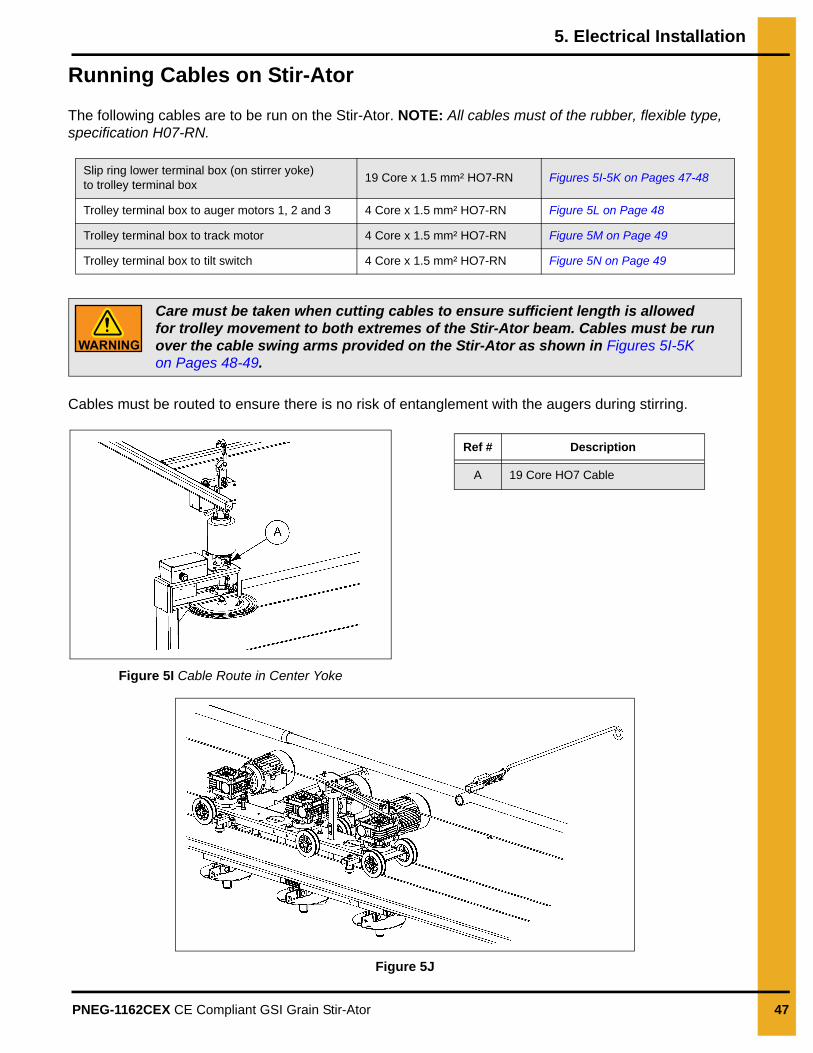
Running Cables on Stir-Ator
The following cables are to be run on the Stir-Ator. NOTE: All cables must of the rubber, flexible type, specification H07-RN.
Cables must be routed to ensure there is no risk of entanglement with the augers during stirring.
Figure 5I Cable Route in Center Yoke
Figure 5J
Slip ring lower terminal box (on stirrer yoke) to trolley terminal box
19 Core x 1.5 mm² HO7-RN Figures 5I-5K on Pages 47-48
Trolley terminal box to auger motors 1, 2 and 3 4 Core x 1.5 mm² HO7-RN Figure 5L on Page 48
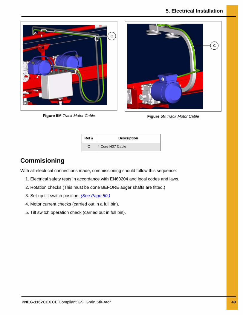
Trolley terminal box to track motor 4 Core x 1.5 mm² HO7-RN Figure 5M on Page 49
Trolley terminal box to tilt switch 4 Core x 1.5 mm² HO7-RN Figure 5N on Page 49
Care must be taken when cutting cables to ensure sufficient length is allowed for trolley movement to both extremes of the Stir-Ator beam. Cables must be run over the cable swing arms provided on the Stir-Ator as shown in Figures 5I-5K on Pages 48-49.
Ref # Description
A 19 Core HO7 Cable
5. Electrical Installation
48 PNEG-1162CEX CE Compliant GSI Grain Stir-Ator
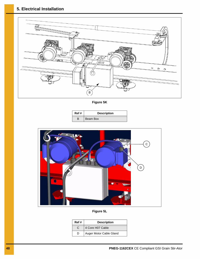
Figure 5K
Figure 5L
Ref # Description
B Beam Box
Ref # Description
C 4 Core H07 Cable
D Auger Motor Cable Gland
C
D
5. Electrical Installation
PNEG-1162CEX CE Compliant GSI Grain Stir-Ator 49
Figure 5M Track Motor Cable Figure 5N Track Motor Cable
Commisioning
With all electrical connections made, commissioning should follow this sequence:
1. Electrical safety tests in accordance with EN60204 and local codes and laws.
2. Rotation checks (This must be done BEFORE auger shafts are fitted.)
3. Set-up tilt switch position. (See Page 50.)
4. Motor current checks (carried out in a full bin).
5. Tilt switch operation check (carried out in full bin).
C
C
Ref # Description
C 4 Core H07 Cable
5. Electrical Installation
50 PNEG-1162CEX CE Compliant GSI Grain Stir-Ator
Setting Up Tilt Switch Operation
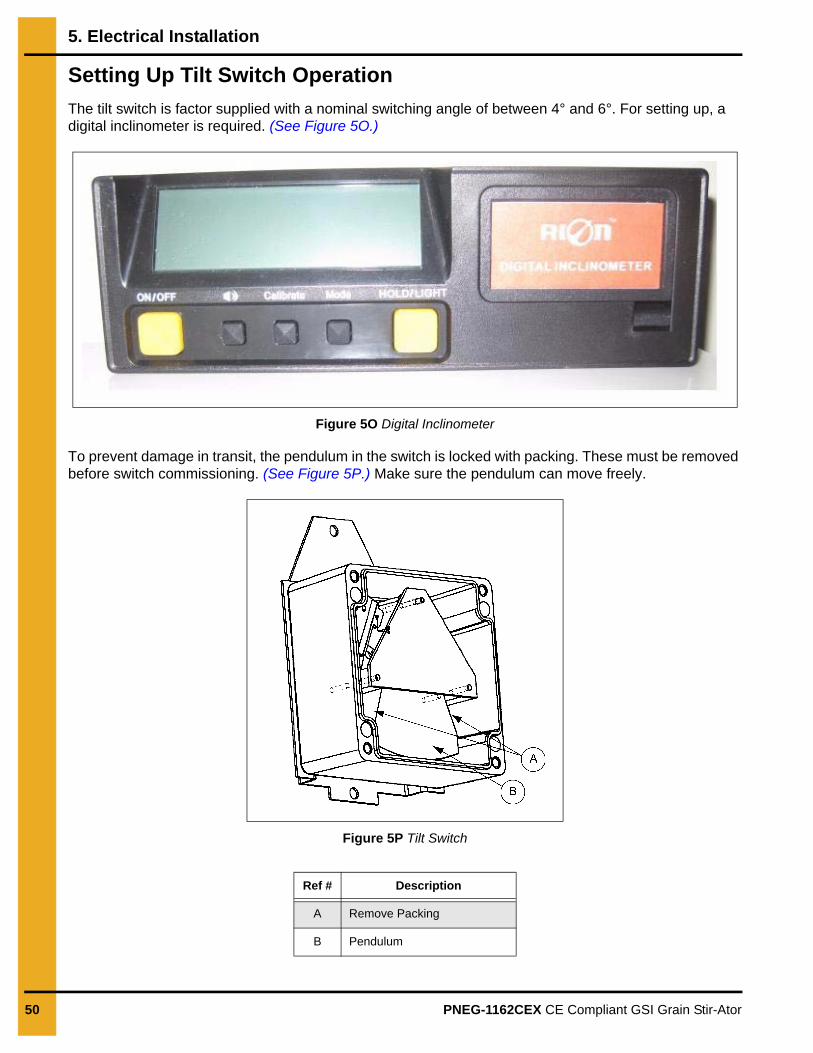
The tilt switch is factor supplied with a nominal switching angle of between 4° and 6°. For setting up, a digital inclinometer is required. (See Figure 5O.)
Figure 5O Digital Inclinometer
To prevent damage in transit, the pendulum in the switch is locked with packing. These must be removed before switch commissioning. (See Figure 5P.) Make sure the pendulum can move freely.
Figure 5P Tilt Switch
Ref # Description
A Remove Packing
B Pendulum
5. Electrical Installation
PNEG-1162CEX CE Compliant GSI Grain Stir-Ator 51
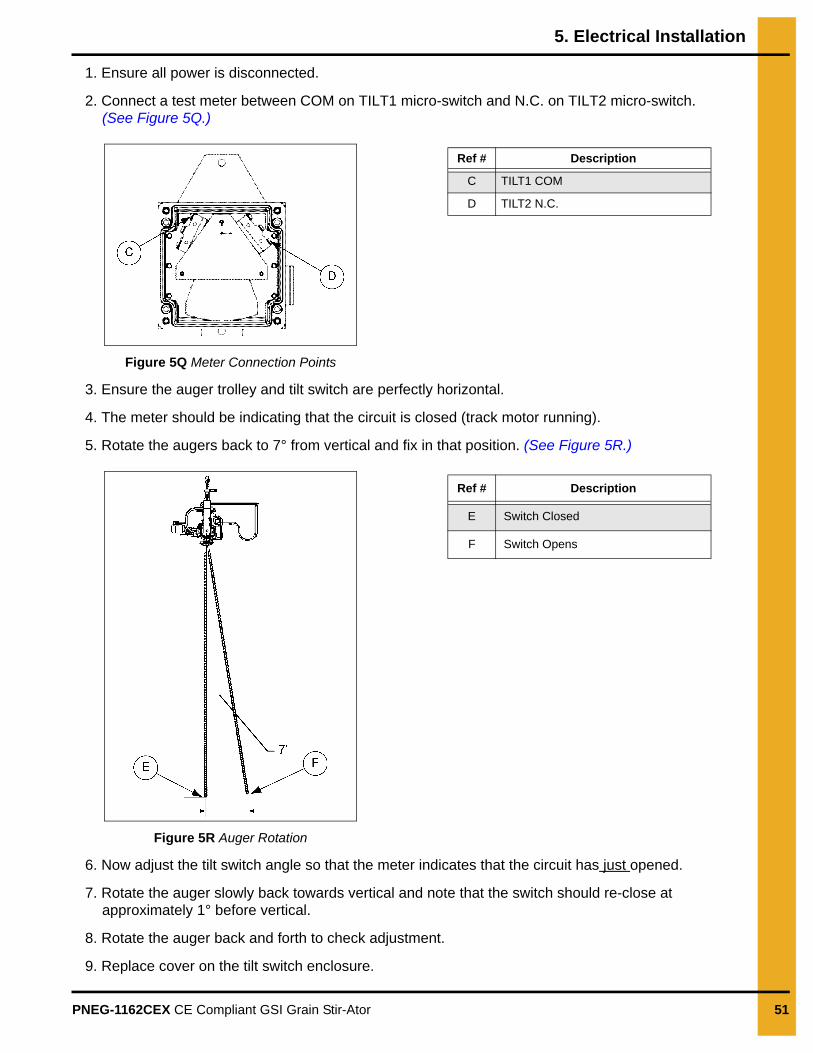
1. Ensure all power is disconnected.
2. Connect a test meter between COM on TILT1 micro-switch and N.C. on TILT2 micro-switch. (See Figure 5Q.)
Figure 5Q Meter Connection Points
3. Ensure the auger trolley and tilt switch are perfectly horizontal.
4. The meter should be indicating that the circuit is closed (track motor running).
5. Rotate the augers back to 7° from vertical and fix in that position. (See Figure 5R.)
Figure 5R Auger Rotation
6. Now adjust the tilt switch angle so that the meter indicates that the circuit has just opened.
7. Rotate the auger slowly back towards vertical and note that the switch should re-close at approximately 1° before vertical.
8. Rotate the auger back and forth to check adjustment.
9. Replace cover on the tilt switch enclosure.
Ref # Description
C TILT1 COM
D TILT2 N.C.
Ref # Description
E Switch Closed
F Switch Opens
52 PNEG-1162CEX CE Compliant GSI Grain Stir-Ator
6. Start-Up
Start-Up in a Full BinStir-Ator augers may become compacted when grain has built up around them and the augers have not been running. Wherever possible we recommend that augers be run as soon as there is 1 m depth of grain covering the augers. However, if for any reason the augers have had to be allowed be covered whilst not running or have stood for a period of a time in a full bin, follow this procedure:
1. Initially try a normal start-up by pressing the start switch ON the control panel. If the augers have not become compacted they will run and should continue running.
2. If the augers are compacted and cannot run, shut the power OFF and lock it so that the augers cannot start inadvertently. Never attempt to start the augers whilst doing this.
3. Entering via the eaves hatch, place wooden planks on the top of the grain so that you can stand safely.
4. Place a long handled vise grip or wrench on the top of the auger shaft and turn the auger by hand to release it.
5. Repeat procedure for other stuck augers.
6. Exit the bin; remove wooden planks; and re-start the auger.
TO HELP PREVENT AUGER COMPACTION, WE RECOMMEND THAT DURING THE STORAGE PERIOD THE AUGERS BE STARTED AND RUN FOR 15 MINUTES EVERY WEEK. THIS WILL KEEP THE AUGERS POLISHED AND HELP PREVENT COMPACTION.
PNEG-1162CEX CE Compliant GSI Grain Stir-Ator 53
7. Parts List
1. Metric Stir-Ator Assembly - (See Page 54-55.)
2. CE Stir-Ator Yoke Assembly - (See Page 56-57.)
3. Frame End Inboard Weldment Assembly - (See Page 58.)
4. Frame Rail Bundle Assembly - (See Page 59.)
5. Drive Arm Assembly - (See Page 60.)
6. CE Stir-Ator Triple Auger Trolley Assembly - (See Page 61.)
7. Suspension Bar Assembly - (See Page 62.)
7. Parts List
54 PNEG-1162CEX CE Compliant GSI Grain Stir-Ator
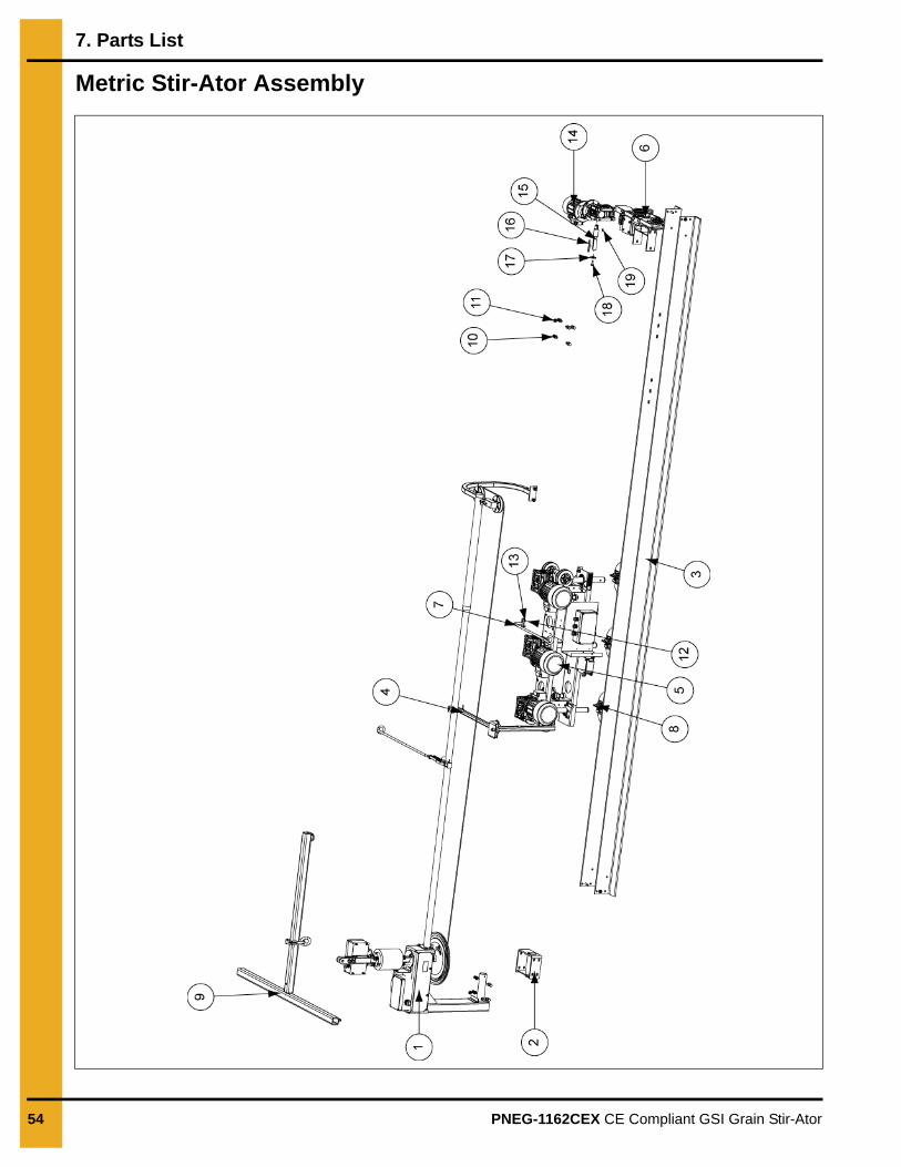
Metric Stir-Ator Assembly
7. Parts List
PNEG-1162CEX CE Compliant GSI Grain Stir-Ator 55
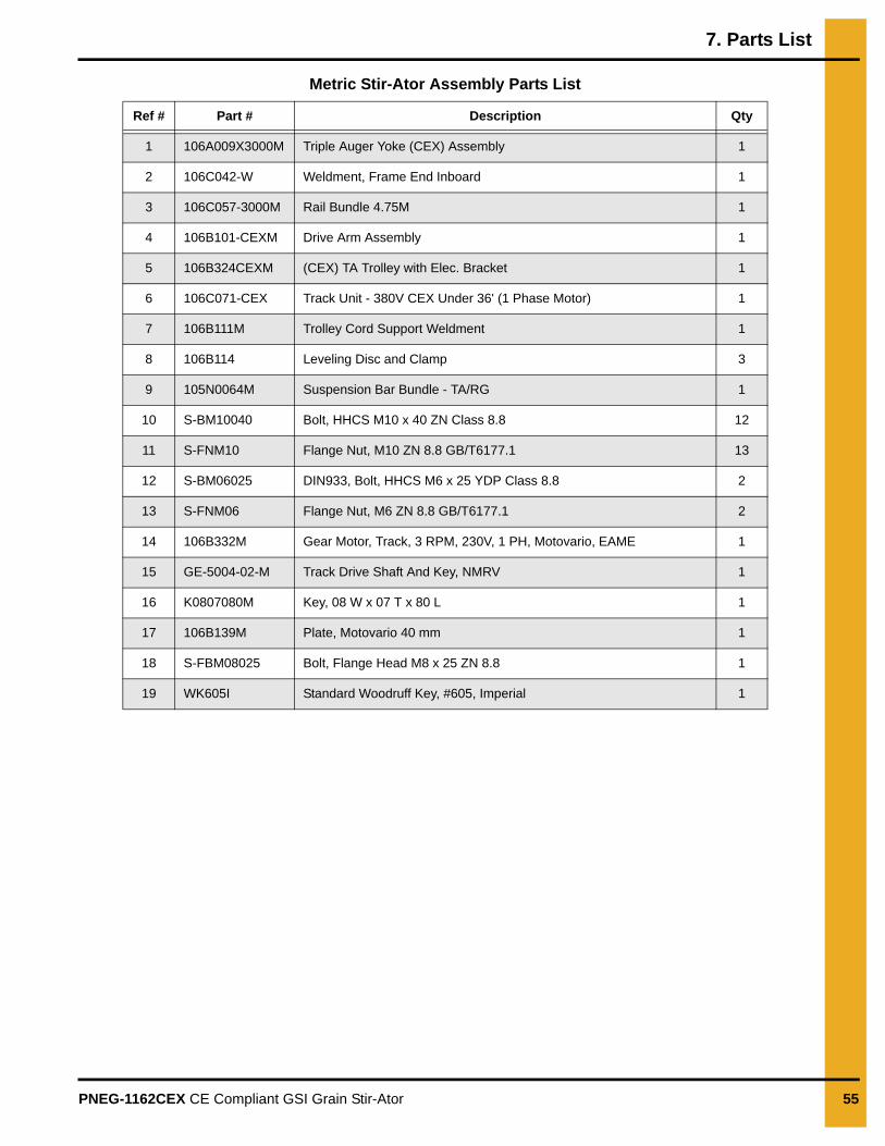
Metric Stir-Ator Assembly Parts List
Ref # Part # Description Qty
1 106A009X3000M Triple Auger Yoke (CEX) Assembly 1
2 106C042-W Weldment, Frame End Inboard 1
3 106C057-3000M Rail Bundle 4.75M 1
4 106B101-CEXM Drive Arm Assembly 1
5 106B324CEXM (CEX) TA Trolley with Elec. Bracket 1
6 106C071-CEX Track Unit - 380V CEX Under 36' (1 Phase Motor) 1
7 106B111M Trolley Cord Support Weldment 1
8 106B114 Leveling Disc and Clamp 3
9 105N0064M Suspension Bar Bundle - TA/RG 1
10 S-BM10040 Bolt, HHCS M10 x 40 ZN Class 8.8 12
11 S-FNM10 Flange Nut, M10 ZN 8.8 GB/T6177.1 13
12 S-BM06025 DIN933, Bolt, HHCS M6 x 25 YDP Class 8.8 2
13 S-FNM06 Flange Nut, M6 ZN 8.8 GB/T6177.1 2
14 106B332M Gear Motor, Track, 3 RPM, 230V, 1 PH, Motovario, EAME 1
15 GE-5004-02-M Track Drive Shaft And Key, NMRV 1
16 K0807080M Key, 08 W x 07 T x 80 L 1
17 106B139M Plate, Motovario 40 mm 1
18 S-FBM08025 Bolt, Flange Head M8 x 25 ZN 8.8 1
19 WK605I Standard Woodruff Key, #605, Imperial 1
7. Parts List
56 PNEG-1162CEX CE Compliant GSI Grain Stir-Ator
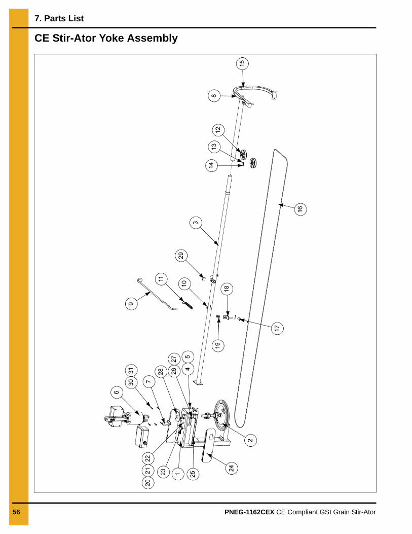
CE Stir-Ator Yoke Assembly
7. Parts List
PNEG-1162CEX CE Compliant GSI Grain Stir-Ator 57
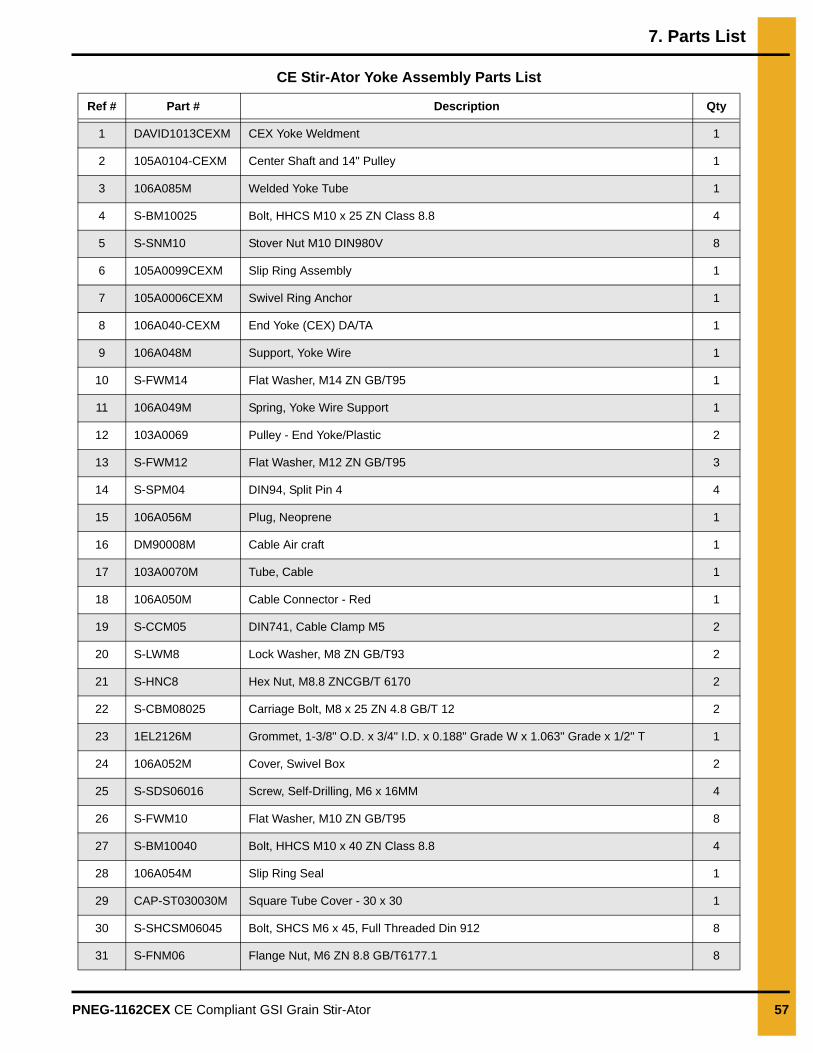
CE Stir-Ator Yoke Assembly Parts List
Ref # Part # Description Qty
1 DAVID1013CEXM CEX Yoke Weldment 1
2 105A0104-CEXM Center Shaft and 14" Pulley 1
3 106A085M Welded Yoke Tube 1
4 S-BM10025 Bolt, HHCS M10 x 25 ZN Class 8.8 4
5 S-SNM10 Stover Nut M10 DIN980V 8
6 105A0099CEXM Slip Ring Assembly 1
7 105A0006CEXM Swivel Ring Anchor 1
8 106A040-CEXM End Yoke (CEX) DA/TA 1
9 106A048M Support, Yoke Wire 1
10 S-FWM14 Flat Washer, M14 ZN GB/T95 1
11 106A049M Spring, Yoke Wire Support 1
12 103A0069 Pulley - End Yoke/Plastic 2
13 S-FWM12 Flat Washer, M12 ZN GB/T95 3
14 S-SPM04 DIN94, Split Pin 4 4
15 106A056M Plug, Neoprene 1
16 DM90008M Cable Air craft 1
17 103A0070M Tube, Cable 1
18 106A050M Cable Connector - Red 1
19 S-CCM05 DIN741, Cable Clamp M5 2
20 S-LWM8 Lock Washer, M8 ZN GB/T93 2
21 S-HNC8 Hex Nut, M8.8 ZNCGB/T 6170 2
22 S-CBM08025 Carriage Bolt, M8 x 25 ZN 4.8 GB/T 12 2
23 1EL2126M Grommet, 1-3/8" O.D. x 3/4" I.D. x 0.188" Grade W x 1.063" Grade x 1/2" T 1
24 106A052M Cover, Swivel Box 2
25 S-SDS06016 Screw, Self-Drilling, M6 x 16MM 4
26 S-FWM10 Flat Washer, M10 ZN GB/T95 8
27 S-BM10040 Bolt, HHCS M10 x 40 ZN Class 8.8 4
28 106A054M Slip Ring Seal 1
29 CAP-ST030030M Square Tube Cover - 30 x 30 1
30 S-SHCSM06045 Bolt, SHCS M6 x 45, Full Threaded Din 912 8
31 S-FNM06 Flange Nut, M6 ZN 8.8 GB/T6177.1 8
7. Parts List
58 PNEG-1162CEX CE Compliant GSI Grain Stir-Ator
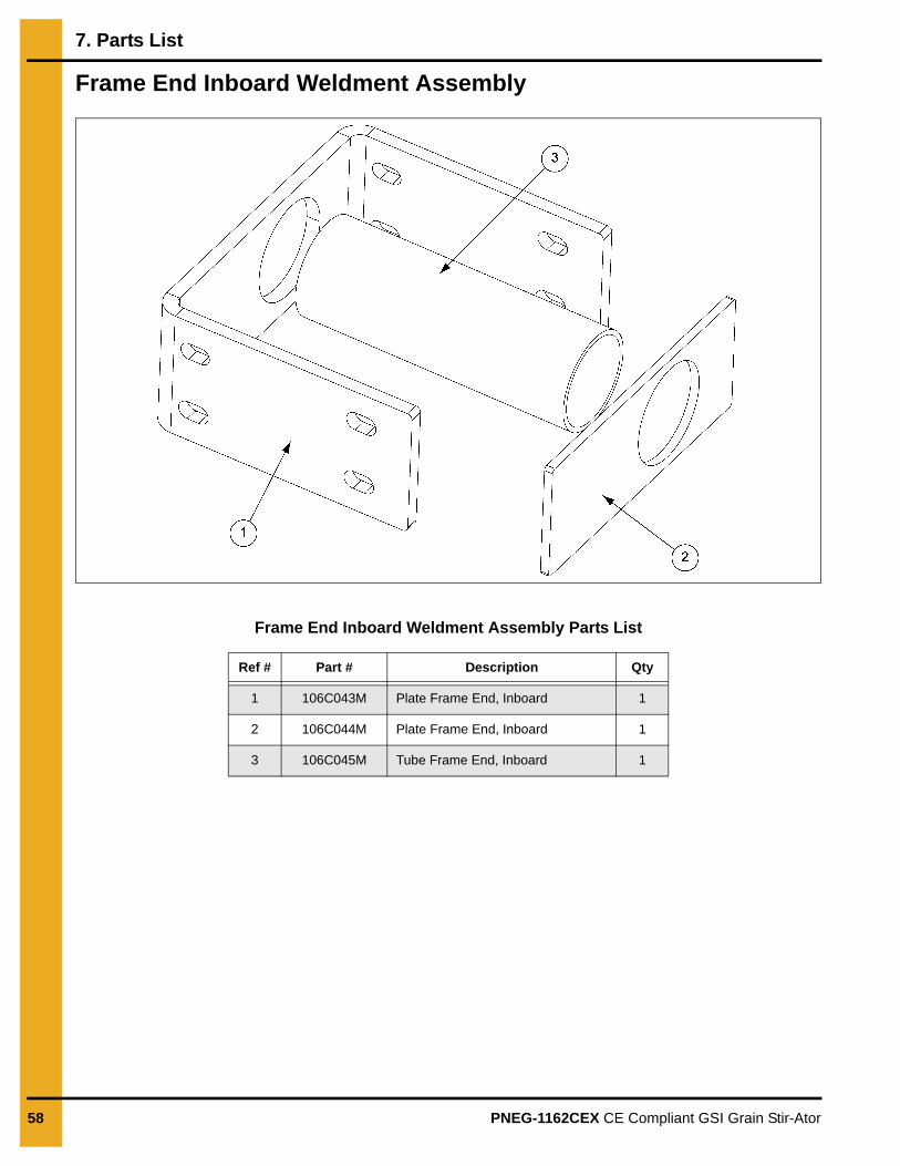
Frame End Inboard Weldment Assembly
Frame End Inboard Weldment Assembly Parts List
Ref # Part # Description Qty
1 106C043M Plate Frame End, Inboard 1
2 106C044M Plate Frame End, Inboard 1
3 106C045M Tube Frame End, Inboard 1
7. Parts List
PNEG-1162CEX CE Compliant GSI Grain Stir-Ator 59
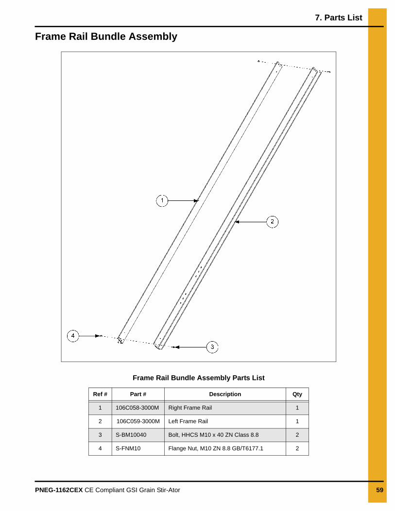
Frame Rail Bundle Assembly
Frame Rail Bundle Assembly Parts List
Ref # Part # Description Qty
1 106C058-3000M Right Frame Rail 1
2 106C059-3000M Left Frame Rail 1
3 S-BM10040 Bolt, HHCS M10 x 40 ZN Class 8.8 2
4 S-FNM10 Flange Nut, M10 ZN 8.8 GB/T6177.1 2
7. Parts List
60 PNEG-1162CEX CE Compliant GSI Grain Stir-Ator
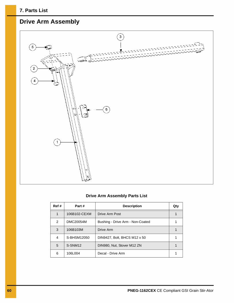
Drive Arm Assembly
Drive Arm Assembly Parts List
Ref # Part # Description Qty
1 106B102-CEXM Drive Arm Post 1
2 DMC20054M Bushing - Drive Arm - Non-Coated 1
3 106B103M Drive Arm 1
4 S-BHSM12050 DIN9427, Bolt, BHCS M12 x 50 1
5 S-SNM12 DIN980, Nut, Stover M12 ZN 1
6 106L004 Decal - Drive Arm 1
7. Parts List
PNEG-1162CEX CE Compliant GSI Grain Stir-Ator 61
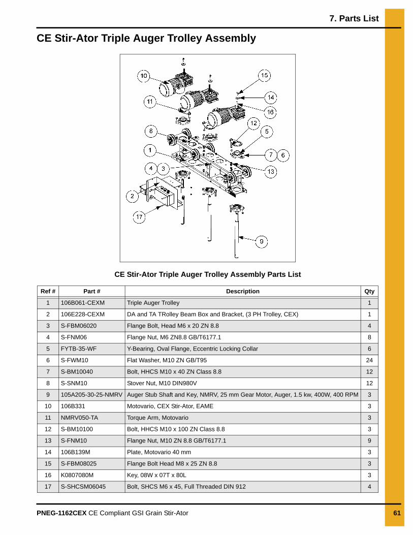
CE Stir-Ator Triple Auger Trolley Assembly
CE Stir-Ator Triple Auger Trolley Assembly Parts List
Ref # Part # Description Qty
1 106B061-CEXM Triple Auger Trolley 1
2 106E228-CEXM DA and TA TRolley Beam Box and Bracket, (3 PH Trolley, CEX) 1
3 S-FBM06020 Flange Bolt, Head M6 x 20 ZN 8.8 4
4 S-FNM06 Flange Nut, M6 ZN8.8 GB/T6177.1 8
5 FYTB-35-WF Y-Bearing, Oval Flange, Eccentric Locking Collar 6
6 S-FWM10 Flat Washer, M10 ZN GB/T95 24
7 S-BM10040 Bolt, HHCS M10 x 40 ZN Class 8.8 12
8 S-SNM10 Stover Nut, M10 DIN980V 12
9 105A205-30-25-NMRV Auger Stub Shaft and Key, NMRV, 25 mm Gear Motor, Auger, 1.5 kw, 400W, 400 RPM 3
10 106B331 Motovario, CEX Stir-Ator, EAME 3
11 NMRV050-TA Torque Arm, Motovario 3
12 S-BM10100 Bolt, HHCS M10 x 100 ZN Class 8.8 3
13 S-FNM10 Flange Nut, M10 ZN 8.8 GB/T6177.1 9
14 106B139M Plate, Motovario 40 mm 3
15 S-FBM08025 Flange Bolt Head M8 x 25 ZN 8.8 3
16 K0807080M Key, 08W x 07T x 80L 3
17 S-SHCSM06045 Bolt, SHCS M6 x 45, Full Threaded DIN 912 4
7. Parts List
62 PNEG-1162CEX CE Compliant GSI Grain Stir-Ator
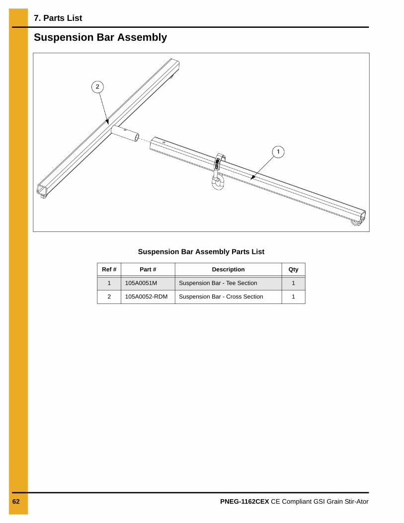
Suspension Bar Assembly
Suspension Bar Assembly Parts List
Ref # Part # Description Qty
1 105A0051M Suspension Bar - Tee Section 1
2 105A0052-RDM Suspension Bar - Cross Section 1
PNEG-1162CEX CE Compliant GSI Grain Stir-Ator 63
8. Warranty
GSI Group, LLC Limited WarrantyThe GSI Group, LLC (“GSI”) warrants products which it manufactures to be free of defects in materials and workmanship under normal usage and conditions for a period of 12 months after sale to the original end-user or if a foreign sale, 14 months from arrival at port of discharge, whichever is earlier. The end-user’s sole remedy (and GSI’s only obligation) is to repair or replace, at GSI’s option and expense, products that in GSI’s judgment, contain a material defect in materials or workmanship. Expenses incurred by or on behalf of the end-user without prior written authorization from the GSI Warranty Group shall be the sole responsibility of the end-user.
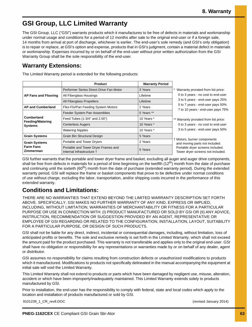
Warranty Extensions:The Limited Warranty period is extended for the following products:
GSI further warrants that the portable and tower dryer frame and basket, excluding all auger and auger drive components, shall be free from defects in materials for a period of time beginning on the twelfth (12th) month from the date of purchase and continuing until the sixtieth (60th) month from the date of purchase (extended warranty period). During the extended warranty period, GSI will replace the frame or basket components that prove to be defective under normal conditions of use without charge, excluding the labor, transportation, and/or shipping costs incurred in the performance of this extended warranty.
Conditions and Limitations:THERE ARE NO WARRANTIES THAT EXTEND BEYOND THE LIMITED WARRANTY DESCRIPTION SET FORTH ABOVE. SPECIFICALLY, GSI MAKES NO FURTHER WARRANTY OF ANY KIND, EXPRESS OR IMPLIED, INCLUDING, WITHOUT LIMITATION, WARRANTIES OF MERCHANTABILITY OR FITNESS FOR A PARTICULAR PURPOSE OR USE IN CONNECTION WITH: (I) PRODUCT MANUFACTURED OR SOLD BY GSI OR (II) ANY ADVICE, INSTRUCTION, RECOMMENDATION OR SUGGESTION PROVIDED BY AN AGENT, REPRESENTATIVE OR EMPLOYEE OF GSI REGARDING OR RELATED TO THE CONFIGURATION, INSTALLATION, LAYOUT, SUITABILITY FOR A PARTICULAR PURPOSE, OR DESIGN OF SUCH PRODUCTS.
GSI shall not be liable for any direct, indirect, incidental or consequential damages, including, without limitation, loss of anticipated profits or benefits. The sole and exclusive remedy is set forth in the Limited Warranty, which shall not exceed the amount paid for the product purchased. This warranty is not transferable and applies only to the original end-user. GSI shall have no obligation or responsibility for any representations or warranties made by or on behalf of any dealer, agent or distributor.
GSI assumes no responsibility for claims resulting from construction defects or unauthorized modifications to products which it manufactured. Modifications to products not specifically delineated in the manual accompanying the equipment at initial sale will void the Limited Warranty.
This Limited Warranty shall not extend to products or parts which have been damaged by negligent use, misuse, alteration, accident or which have been improperly/inadequately maintained. This Limited Warranty extends solely to products manufactured by GSI.
Prior to installation, the end-user has the responsibility to comply with federal, state and local codes which apply to the location and installation of products manufactured or sold by GSI.
Product Warranty Period
AP Fans and Flooring
Performer Series Direct Drive Fan Motor 3 Years * Warranty prorated from list price:
0 to 3 years - no cost to end-user
3 to 5 years - end-user pays 25%
5 to 7 years - end-user pays 50%
7 to 10 years - end-user pays 75%
** Warranty prorated from list price:
0 to 3 years - no cost to end-user
3 to 5 years - end-user pays 50%
† Motors, burner components and moving parts not included. Portable dryer screens included. Tower dryer screens not included.
All Fiberglass Housings Lifetime
All Fiberglass Propellers Lifetime
AP and Cumberland Flex-Flo/Pan Feeding System Motors 2 Years
Cumberland Feeding/Watering Systems
Feeder System Pan Assemblies 5 Years **
Feed Tubes (1-3/4" and 2.00") 10 Years *
Centerless Augers 10 Years *
Watering Nipples 10 Years *
Grain Systems Grain Bin Structural Design 5 Years
Grain SystemsFarm FansZimmerman
Portable and Tower Dryers 2 Years
Portable and Tower Dryer Frames and Internal Infrastructure †
5 Years
9101239_1_CR_rev8.DOC (revised January 2014)

This equipment shall be installed in accordance with the current installation codes and applicable
regulations, which should be carefully followed in all cases. Authorities having jurisdiction should be
consulted before installations are made.
1004 E. Illinois St. Assumption, IL 62510-0020
Phone: 1-217-226-4421 Fax: 1-217-226-4420
www.gsiag.com
Copyright © 2016 by The GSI Group, LLCPrinted in the USA
GSI is a worldwide brand of AGCO Corporation.
CN-326169