p/n 5900108 installation and operation manual manual 5900108 rev e 08-07-12.pdf · installation and...
TRANSCRIPT

INSTALLATION AND OPERATION MANUAL
SHIPPING DAMAGE CLAIMSWhen this equipment is shipped, title passes to the purchaser upon receipt from the carrier. Consequently, claims for the material damaged in shipment must be made by the purchaser against the transportation company at the time shipment is received.
BE SAFEYour new lift was designed and built with safety in mind. However, your overall safety can be increased by proper training and thoughtful operation on the part of the operator. DO NOT operate or repair this equipment without reading this manual and the important safety instructions shown inside.
1645 Lemonwood Dr.Santa Paula, CA. 93060, USA
Toll Free 1-800-253-2363Tel: 1-805-933-9970Fax: 1-805-933-9160
www.bendpak.com
6,000 POUND CAPACITYPORTABLE MID RISE LIFT
MODEL: MD-6XP
PLEASE READ THE ENTIRE CONTENTS OF THIS MANUAL PRIOR TO INSTALLATION AND OPERATION. BY PROCEEDING YOU AGREE THAT YOU FULLY UNDERSTAND AND COMPREHEND THE FULL CONTENTS OF THIS MANUAL. FORWARD THIS MANUAL TO ALL OPERATORS. FAILURE TO OPERATE THIS EQUIPMENT AS DIRECTED MAY CAUSE INJURY OR DEATH.
REV E 08-11-2014p/n 5900108
Keep this operation manual near the machine at all times. Make sure that
ALL USERS read this manual.DRAFT
2
6,000 POUND CAPACITYMID RISE LIFT
This instruction manual has been prepared especially for you. Your new lift is the product of over 35 years of continuous research, testing and development;
it is the most technically advanced lift on the market today.
READ THIS ENTIRE MANUAL BEFORE INSTALLATION & OPERATION BEGINS.
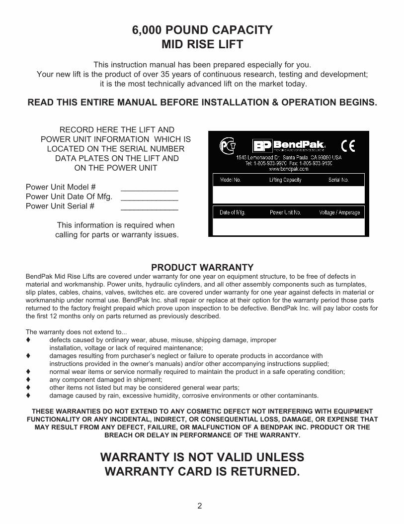
RECORD HERE THE LIFT ANDPOWER UNIT INFORMATION WHICH IS
LOCATED ON THE SERIAL NUMBER DATA PLATES ON THE LIFT AND
ON THE POWER UNIT
Power Unit Model # _____________Power Unit Date Of Mfg. _____________Power Unit Serial # _____________
This information is required when calling for parts or warranty issues.
PRODUCT WARRANTYBendPak Mid Rise Lifts are covered under warranty for one year on equipment structure, to be free of defects in material and workmanship. Power units, hydraulic cylinders, and all other assembly components such as turnplates, slip plates, cables, chains, valves, switches etc. are covered under warranty for one year against defects in material or workmanship under normal use. BendPak Inc. shall repair or replace at their option for the warranty period those parts returned to the factory freight prepaid which prove upon inspection to be defective. BendPak Inc. will pay labor costs for the first 12 months only on parts returned as previously described.
The warranty does not extend to...t defects caused by ordinary wear, abuse, misuse, shipping damage, improper installation, voltage or lack of required maintenance;t damages resulting from purchaser’s neglect or failure to operate products in accordance with instructions provided in the owner’s manuals) and/or other accompanying instructions supplied;t normal wear items or service normally required to maintain the product in a safe operating condition;t any component damaged in shipment;t other items not listed but may be considered general wear parts;t damage caused by rain, excessive humidity, corrosive environments or other contaminants.
THESE WARRANTIES DO NOT EXTEND TO ANY COSMETIC DEFECT NOT INTERFERING WITH EQUIPMENT FUNCTIONALITY OR ANY INCIDENTAL, INDIRECT, OR CONSEQUENTIAL LOSS, DAMAGE, OR EXPENSE THAT
MAY RESULT FROM ANY DEFECT, FAILURE, OR MALFUNCTION OF A BENDPAK INC. PRODUCT OR THE BREACH OR DELAY IN PERFORMANCE OF THE WARRANTY.
WARRANTY IS NOT VALID UNLESSWARRANTY CARD IS RETURNED.

3
IMPORTANT NOTICEDo not attempt to install this lift if you have never been trained on basic automotive lift installation procedures. Never attempt to lift components without proper lifting tools such as forklift or cranes. Stay clear of any moving parts that can fall and cause injury. These instructions must be followed to ensure proper installation and operation of your lift. Failure to comply with these instructions can result in serious bodily harm and void product warranty. Manufacturer will assume no liability for loss or damage of any kind, expressed or implied resulting from improper installation or use of this product.
PLEASE READ ENTIRE MANUAL PRIOR TO INSTALLATION.
DEFINITIONS OF HAZARD LEVELS
Identify the hazard levels used in this manual with the following definitions and signal words:
DANGER !Watch for this symbol: It Means: Immediate hazards which will result in severe personal injury or death.
WARNING !Watch for this symbol: It Means: Hazards or unsafe
practices which could result in severe personal injury or death.
CAUTION !Watch for this symbol: It Means: Hazards or unsafe practices which may result in minor personal injury,
product or property damage.
OWNER’S RESPONSIBILITYTo maintain the lift and user safety, the responsibility of the owner is to read and follow these instructions:
tFollow all installation and operation instructions.tMake sure installation conforms to all applicable Local, State, and Federal Codes, Rules, and Regulations; such as State and Federal OSHA Regulations and Electrical Codes.tCarefully check the lift for correct initial function.tRead and follow the safety instructions. Keep them readily available for machine operators.tMake certain all operators are properly trained, know how to safely and correctly operate the unit, and are properly supervised.tAllow unit operation only with all parts in place and operating safely.tCarefully inspect the unit on a regular basis and perform all maintenance as required.tService and maintain the unit only with authorized or approved replacement parts.tKeep all instructions permanently with the unit and all decals on the unit clean and visible.
BEFORE YOU BEGIN
Receiving:The shipment should be thoroughly inspected as soon as it is received. The signed bill of lading is acknowledgement by the carrier of receipt in good condition of shipment covered by your invoice. If any of the goods called for on this bill of lading are shorted or damaged, do not accept them until the carrier makes a notation on the freight bill of the shorted or damaged goods. Do this for your own protection.
NOTIFY THE CARRIER AT ONCE if any hidden loss or damage is discovered after receipt and request the carrier to make an inspection. If the carrier will not do so, prepare a signed statement to the effect that you have notified the carrier (on a specific date) and that the carrier has failed to comply with your request.
IT IS DIFFICULT TO COLLECT FOR LOSS OR DAMAGE AFTER YOU HAVE GIVEN THE CARRIER A CLEAR RECEIPT. File your claim with the carrier promptly. Support your claim with copies of the bill of lading, freight bill, invoice, and photographs, if available. Our willingness to assist in helping you process your claim does not make BendPak responsible for collection of claims or replacement of lost or damaged materials.
4
TABLE OF CONTENTS
Contents Page No.
Warranty / Serial Number Information . . . . . . . . . . . . . . . . . . . . . . . . . . . . . . . . . . . . . . . . . . . . . . . . . . . . . . . . . . . . . 2
Definitions of Hazard Levels . . . . . . . . . . . . . . . . . . . . . . . . . . . . . . . . . . . . . . . . . . . . . . . . . . . . . . . . . . . . . . . . . . . . .3
Owner’s Responsibility . . . . . . . . . . . . . . . . . . . . . . . . . . . . . . . . . . . . . . . . . . . . . . . . . . . . . . . . . . . . . . . . . . . . . . . . .3
Before You Begin . . . . . . . . . . . . . . . . . . . . . . . . . . . . . . . . . . . . . . . . . . . . . . . . . . . . . . . . . . . . . . . . . . . . . . . . . . . . 3
Table Of Contents . . . . . . . . . . . . . . . . . . . . . . . . . . . . . . . . . . . . . . . . . . . . . . . . . . . . . . . . . . . . . . . . . . . . . . . . . . . . 4
Installer / Operator Instructions . . . . . . . . . . . . . . . . . . . . . . . . . . . . . . . . . . . . . . . . . . . . . . . . . . . . . . . . . . . . . . . . . . 5
Safety / Warning Instructions . . . . . . . . . . . . . . . . . . . . . . . . . . . . . . . . . . . . . . . . . . . . . . . . . . . . . . . . . . . . . . . . . . . 6
Tools Required . . . . . . . . . . . . . . . . . . . . . . . . . . . . . . . . . . . . . . . . . . . . . . . . . . . . . . . . . . . . . . . . . . . . . . . . . . . . . .7
Step 1 / Selecting Site . . . . . . . . . . . . . . . . . . . . . . . . . . . . . . . . . . . . . . . . . . . . . . . . . . . . . . . . . . . . . . . . . . . . . . . . .7
Step 2 / Floor Requirements . . . . . . . . . . . . . . . . . .. . . . . . . . . . . . . . . . . . . . . . . . . . . . . . . . . . . . . . . . . . . . . . . . . . .7
Concrete Specifications . . . . . . . . . . . . . . . . . . . . . . . . . . . . . . . . . . . . . . . . . . . . . . . . . . . . . . . . . . . . . . . . . . . . . . . 7
Assembly View / Description of Parts . . . . . . . . . . . . . . . . . . . . . . . . . . . . . . . . . . . . . . . . . . . . . . . . . . . . . . . . . . . . . . 8
Floor Plan / Specifications . . . . . . . . . . . . . . . . . . . . . . . . . . . . . . . . . . . . . . . . . . . . . . . . . . . . . . . . . . . . . . . . . . . . . .9
Step 3 / Power Unit Set Up . . . . . . . . . . . . . . . . . . . . . . . . . . . . . . . . . . . . . . . . . . . . . . . . . . . . . . . . . . . . . . . . . . . .10
Step 4 / Connecting Hydraulic Hoses Fittings . . . . . . . . . . . . . . . . . . . . . . . . . . . . . . . . . . . . . . . . . . . . . . . . . . . . . . 10
Step 5 / Lift Arm Installation . . . . . . . . . . . . . . . . . . . . . . . . . . . . . . . . . . . . . . . . . . . . . . . . . . . . . . . . . . . . . . . . . . . .11
Step 6 / Installing/ Changing Lift Pads . . . . . . . . . . . . . . . . . . . . . . . . . . . . . . . . . . . . . . . . . . . . . . . . . . . . . . . . . . . . 11
Step 7 / Wiring Power Unit . . . . . . . . . . . . . . . . . . . . . . . . . . . . . . . . . . . . . . . . . . . . . . . . . . . . . . . . . . . . . . . . . . . . .12
Step 8 / Lift Start Up / Final Adjustments . . . . . . . . . . . . . . . . . . . . . . . . . . . . . . . . . . . . . . . . . . . . . . . . . . . . . . . . . .14-15
Step 9 Bleeding . . . . . . . . . . . . . . . . . . . . . . . . . . . . . . . . . . . . . . . . . . . . . . . . . . . . . . . . . . . . . . . . . . . . . . . . . . . . .15
Post Installation Check-Off . . . . . . . . . . . . . . . . . . . . . . . . . . . . . . . . . . . . . . . . . . . . . . . . . . . . . . . . . . . . . . . . . . . 15
Step 10 / Operation/ Maintenance . . . . . . . . . . . . . . . . . . . . . . . . . . . . . . . . . . . . . . . . . . . . . . . . . . . . . . . . . . . . .16-25
Troubleshooting Guide . . . . . . . . . . . . . . . . . . . . . . . . . . . . . . . . . . . . . . . . . . . . . . . . . . . . . . . . . . . . . . . . . . . . . 26-29
Parts Breakdown . . . . . . . . . . . . . . . . . . . . . . . . . . . . . . . . . . . . . . . . . . . . . . . . . . . . . . . . . . . . . . . . . . . . . . . . . . 30-32
Maintenance Records . . . . . . . . . . . . . . . . . . . . . . . . . . . . . . . . . . . . . . . . . . . . . . . . . . . . . . . . . . . . . . . . . . . . . . 33-34

5
INSTALLER / OPERATORPLEASE READ AND FULLY
UNDERSTAND. BY PROCEEDING YOU AGREE TO
THE FOLLOWING.
tI have visually inspected the site where the lift is to be installed and verified the concrete to be in good condition and free of cracks or other defects. I understand that installing a lift on cracked or defective concrete could cause lift failure resulting in personal injury or death.
t I understand that a level floor is required for proper installation and level lifting.
t I understand that I am responsible if my floor is of questionable slope and that I will be responsible for all charges related to pouring a new level concrete slab if required and any charges.
t I understand that the lifts are supplied with concrete fasteners meeting the criteria of the American National Standard “Automotive Lifts - Safety Requirements for Construction, Testing, and Validation” ANSI/ALI ALCTV-2006, and that I will be responsible for all charges related to any special regional structural and/or seismic anchoring requirements specified by any other agencies and/or codes such as the Uniform Building Code (UBC) and/or International Building Code (IBC).
t I will assume full responsibility for the concrete floor and condition thereof, now or later, where the above equipment model(s) are to be installed. Failure to follow danger, warning, and caution instructions may lead to serious personal injury or death to operator or bystander or damage to property.
t I understand that BendPak lifts are designed to be installed in indoor locations only. Failure to follow installation instructions may lead to serious personal injury or death to operator or bystander or damage to property or lift.
Failure to follow danger, warning, and caution instructions may lead to serious personal injury or death
to operator or bystander or damage to property.
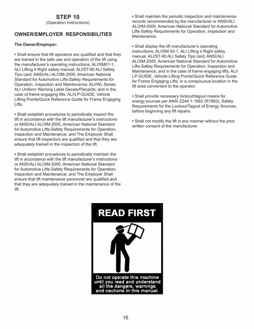
Please read entire manual prior to installation.Do not operate this machine until you read and
understand all the dangers, warnings and cautions in this manual. For additional copies
or further information, contact:
BendPak Inc. / Ranger Products1645 Lemonwood Dr.
Santa Paula, CA. 93060
1-805-933-9970
www.bendpak.com
INSTALLER / OPERATORPROTECTIVE EQUIPMENT
Personal protective equipment helps makes installation and operation safer, however, it does not take the place of safe operating practices. Always wear durable work clothing during any installation and/or service activity. Shop aprons or shop coats may also be worn, however loose fitting clothing should be avoided. Tight fitting leather gloves are recommended to protect technician hands when handling parts. Sturdy leather work shoes with steel toes and oil resistant soles should be used by all service personnel to help prevent injury during typical installation and operation activities. Eye protection is essential during installation and operation activities. Safety glasses with side shields, goggles, or face shields are acceptable. Back belts provide support during lifting activities and are also helpful in providing worker protection. Consideration should also be given to the use of hearing protection if service activity is performed in an enclosed area, or if noise levels are high.
THIS SYMBOL POINTS OUT IMPORTANT SAFETY INSTRUCTIONS WHICH IF NOT FOLLOWEDCOULD ENDANGER THE PERSONAL SAFETY AND/OR PROPERTY OR YOURSELF AND OTHERSAND CAN CAUSE PERSONAL INJURY OR DEATH. READ AND FOLLOW ALL INSTRUCTIONS IN
THIS MANUAL BEFORE ATTEMPTING TO OPERATE THIS MACHINE.

6
1. Carefully remove the crating and packing materials. CAUTION! Be careful when cutting steel banding material as items may become loose and fall causing personal harm or injury.
2. Check the voltage, phase and proper amperage requirements for the motor shown on the motor plate. Wiring should be performed by a certified electrician only.
IMPORTANT SAFETY INSTRUCTIONS !Read these safety instructions entirely!
IMPORTANT NOTICE !Do not attempt to install this lift if you have never been trained on basic automotive lift installation procedures.
Never attempt to lift components without proper lifting tools such as forklift or cranes. Stay clear of any moving parts that can fall and cause injury.
INTRODUCTION
1. READ AND UNDERSTAND all safety warning procedures before operating lift.
2. KEEP HANDS AND FEET CLEAR. Remove hands and feet from any moving parts. Keep feet clear of lift whenlowering. Avoid pinch points.
3. KEEP WORK AREA CLEAN. Cluttered work areas invite injuries.
4. Consider work area environment. Do not expose equipment to rain. DO NOT use in damp or wet locations. Keep area well lighted.
5. ONLY TRAINED OPERATORS should operate this lift. All non-trained personnel should be kept away from work area. Never let non-trained personnel come in contact with, or operate lift.
6. USE LIFT CORRECTLY. Use lift in the proper manner. Never use lifting adapters other than what is approved by the manufacturer.
7. DO NOT override self-closing lift controls.
8. REMAIN CLEAR of lift when raising or lowering vehicle.
9. CLEAR AREA if vehicle is in danger of falling.
10. ALWAYS ENSURE that the safeties are engaged before any attempt is made to work on or near vehicle.
11. DRESS PROPERLY. Non-skid steel-toe footwear is recommended when operating lift.
12. GUARD AGAINST ELECTRIC SHOCK. This lift must be grounded while in use to protect the operator from electric shock. Never connect the green power cord wire to a live terminal. This is for ground only.
13. DANGER! The power unit used on this lift contains high voltage. Disconnect power at the receptacle before performing any electrical repairs. Secure plug so that it cannot be accidentally plugged in during service.
14. WARNING! RISK OF EXPLOSION. This equipment has internal arcing or sparking parts which should not be exposed to flammable vapors. This machine should not be located in a recessed area or below floor level.
15. MAINTAIN WITH CARE. Keep lift clean for better and safer performance. Follow manual for proper lubrication and maintenance instructions. Keep control handles and/or buttons dry, clean and free from grease and oil.
16. STAY ALERT. Watch what you are doing. Use common sense. Be aware.
17. CHECK FOR DAMAGED PARTS. Check for alignment of moving parts, breakage of parts or any condition that may affect its operation. Do not use lift if any component is broken or damaged.
18. NEVER remove safety related components from the lift. Do not use lift if safety related components are damaged or missing.

7
STEP 1(Selecting Site)
Before installing your new lift, check the following.
1. LIFT LOCATION: Always use architects plans when available. Check layout dimension against floorplan requirements making sure that adequate space if avail-able.
2. OVERHEAD OBSTRUCTIONS: The area where the lift will be located should be free of overhead obstruc-tions such as heaters, building supports, electrical lines etc.
3. DEFECTIVE FLOOR: Visually inspect the site where the lift is to be installed and check for cracked or defec-tive concrete.
4. OPERATING TEMPERATURE. Operate lift only between temperatures of 41° -104° F.
5. Lift is designed for INDOOR INSTALLATION ONLY.
STEP 2(Floor Requirements)
This lift must be installed on a solid level concrete floor with no more than 3-degrees of slope. Failure to do so could cause personal injury or death.
A level floor is suggested for proper use and installa-tion and level lifting. If a floor is of questionable slope, consider a survey of the site and/or the possibility of pour-ing a new level concrete slab.
t DO NOT install or use this lift on any asphalt surface or any surface other than concrete.
t DO NOT install or use this lift on expansion seams or on cracked or defective concrete.
t DO NOT install or use this lift on a second / elevated floor without first consulting building architect.
t DO NOT install or use this lift outdoors.
CONCRETE SPECIFICATIONS
LIFT MODEL CONCRETE REQUIREMENTS MD-6XP 3.5” Min. Thickness / 2,500 PSI
DANGER!All models MUST be installed on 3,000 PSI concrete only conforming to the minimum requirements shown above.
New concrete must be adequately cured by at least 28 days minimum.
IMPORTANT NOTICE !These instructions must be followed to ensure proper installation and operation of your lift.
Failure to comply with these instructions can result in serious bodily harm and void product warranty. Manufacturer will assume no liability for loss or damage of any kind, expressed or implied resulting
from improper installation or use of this product. PLEASE READ ENTIRE MANUAL PRIOR TO INSTALLATION !
t4 Foot LeveltSmall Adjustable Wrench
tLarge Adjustable Wrencht12mm Hex Key
TOOLS REQUIRED

8
Assembly View
PART # DESCRIPTION QTY 5215264 LIFT ARM ASSEMBLY 4 5215252 SHORT LIFT PAD ASSEMBLY 4 5600257 LIFT PAD WELDMENT BASE 4 5746390 SHORT LIFT PAD EXTENSION (113mm LG.) 4 5570013 HOSE ASSEMBLY Ø6.4 x 3660mm SB 1 5570054 HOSE ASSEMBLY Ø6.4 x 540mm DS 15585094 Power Unit AB-1380; 110 / 220 Volt, 60HZ, 1 Phase* 15215263 POWER UNIT STAND ASSEMBLY 1
Lift Arm Assembly
Power Unit Stand Assembly
Short Lift Pad Assembly
Short Lift Pad Extension
Lift Pad Weldment
Base
Hose Assembly Ø6.4 x 3660mm SB
Hose Assembly Ø6.4 x 540mm DS

9
Lifting Capacity Lifting Time Power Unit
6,000 Lbs. / 2721 Kgs. 45 Sec. 110/220VAC50/60HZ *
*Must specify at time of ordering.

10
STEP 3(Power Unit Set Up)
1. Set the Power Unit on the Stand/Tow Handle and mount using the four M8 x 1.25 x 20mm Bolts, Nuts and Washers. (See Fig 3.1)
2. Remove plug from power unit and install the 90° Fitting w/ O-ring into the power port on the Power Unit. Take care to make sure the O-ring seats properly.
3. Connect the 144” Hydraulic Hose to the 90° Fitting.
4. Fill the reservoir with 6 Quarts/ 1.5 gals of Dexron III ATF or 10W Non-foaming hydraulic fluid.
STEP 4(Connecting Hydraulic Fittings / Hoses)
1. Remove the plastic plug from the left port of the left hand Cylinder.
2. Install the Straight Hydraulic Fitting in the left port of the left hand Cylinder. Use Teflon tape on the Cylinder side on the Fitting only.
3. Attach the 144” Hydraulic Hose to the Straight Fitting in the port of the left hand side Cylinder.
4. Check the 21.25” Hose connections and 90* Fittings on the right side of the left side Cylinder Fitting. Then check the other end of the 21.25” Hose and 90° Fitting on the left fitting side of the right hand Cylinder. 5. The right side hydraulic port of the right Cylinder should be plugged with a metal plug. Check plug and tighten if necessary. (See Fig 4.1)
Fig 3.1
Fig 4.1.

11
STEP 5(Lift Arm Installation)
1. Set the Adjustable Arm on the Ramp ensuring that the Bolt on the arm is inserted through the arm holder channel on the side of the ramp. (See Fig. 5.1)
3. Tighten the M-20-10 nut until the arm cannot pivot, then back the nut off until the arm is just loose enough to pivot freely. (See Fig.5.2)
STEP 6(Installing / Changing Lift Pads)
1. Remove the Socket Head Screw from the end of the lift arm.
2. Slide the desired height Lift Pad riser onto the lift arm.Replace and tighten the Socket head Screw. Drop in the Lift Pad if applicable. (See Fig.3.)
Repeat the above procedure for the other three arms.
4. Use the 3” Lift Pad Extension as necessary to reach proper lifting points on the vehicle.
Fig 5.1
Fig 6.1
Fig 5.2
WARNING!ALWAYS set the adjustable arms and pads under the proper lifting points as indicated in the Lifting Guide or
owners manual of the vehicle.
Lift Pad As-sembly
M12 x 1.75 x 20mm Screw
M20 Flat Washer
M20 x 2.5 Nylock nut

12
STEP 7(Wiring Hydraulic Power Unit)
1. Have a certified electrician run the power supply to motor. Refer to the data plate found on the motor for proper power supply and wire size.
WARNING!
DO NOT run power unit with no oil. Damage to pump can occur. The power unit must be kept dry. Damage to power unit caused by water or other liquids such as
detergents, acid etc., is not covered under warranty.Operate lift only between temperatures of 41 °- 104° F.
Improper electrical hook-up can damage motor and will not be covered under warranty.Motor can not run on 50HZ without a physical change in motor.
Use a separate breaker for each power unit.Protect each circuit with time delay fuse or circuit breaker.
For 110-120 volt, single phase, use a 25 amp fuse.
DANGER!
ALL WIRING MUST BE PERFORMED BY A LICENSED ELECTRICIAN.
DANGER!
DO NOT PERFORM ANY MAINTENANCE OR INSTALLATION OF ANY COMPONENTS WITH OUT FIRST ENSURING THAT ELECTRICAL POWER HAS
BEEN DISCONNECTED AT THE SOURCE OR PANEL AND CANNOT BE RE-ENERGIZED UNTIL ALL
MAINTENANCE AND/OR INSTALLATION PROCEDURES ARE COMPLETED.
WARNING!
RISK OF EXPLOSION!This equipment has internal arcing or parts that
may spark and should not be exposed to flammable vapors. Motor should not be located in a recessed area or below floor level. NEVER expose motor to rain or other damp environments. DAMAGE TO MOTOR CAUSED BY WATER IS NOT COVERED
UNDER WARRANTY.

13

14
STEP 8(Lift Start Up / Final Adjustments)
1. Make sure the Power Unit reservoir is full with 6 quarts/ 1.5 gals of 10-WT hydraulic oil or Dexron-III automatic transmission fluid.
2. Check the MAIN SAFETY LOCK to make sure it moves freely and springs back to the lock position when released. Lubricate all SAFETY PIVOT points with WD-40 or equal.
3. Test the Power Unit by pressing the push-button switch. If the motor sounds like it is operating properly, raise the lift and check all hose connections for leaks. If the motor gets hot or sounds peculiar, stop and check all electrical connections.
4. Raise lift until THE CYLINDER BOTTOMS OUT AND THE LIFT STOPS.
Keep hands and feet clear. Remove hands and feet from any moving parts. Keep feet clear of lift when
lowering. Avoid pinch points.
ALWAYS WEAR SAFETY GOGGLES.
5. Verify that the safety rests in the locked position at each safety stop. Safety is locked when a Safety Block is resting on Safety Pin. (See Fig. 8.1 & 8.2)
DANGER! VISUALLY CONFIRM THAT ALL PRIMARY SAFETY LOCKS ARE ENGAGED BEFORE
ENTERING WORK AREA.Suspension components us on this lift are
intended to raise and lower lift only and are not meant to be load holding devices. Remain
clear of elevated lift unless visual confirmation is made that all primary Safety
Locks are fully engaged and the lift is LOWERED onto the Safety Locks. Refer to
installation /operation manual for proper Safety Lock procedures and /or further instruction.
Fig 8.1
Fig 8.2

15
6. Raise the lift off the safety locks by pressing the push button on the power unit. Make sure you raise the lift by at least two inches to allow adequate clearance for the safety lock to clear. ( See Fig. 8.3 - 8.5)
8. Lower lift by depressing lowering valve on power unit.
9. Run the lift up and down a few times to ensure that the locks are engaging uniformly and that the safety release mechanisms are functioning. Re-adjust if necessary
STEP 9(Bleeding)
1. Lift must be fully lowered before changing or adding fluid.
2. Raise and lower lift six times. The cylinder is self bleeding. After bleeding system, fluid level in power unit reservoir may be down. Add more fluid if necessary to raise lift to full height. It is only necessary to add fluid to raise lift to full height.
3. To pressure test, run lift to full rise and run motor for approximately 3-seconds after lift stops. This will place pressure on the hydraulic system. Stop and check all fittings and hose connections. Tighten or reseal if required.
POST-INSTALLATION CHECK-OFF
tLift Assembly, Level And Stable tArm Assemblies Properly Attached tElectric Power Supply Confirmed tSafety Locks Functioning ProperlytCheck For Hydraulic LeakstOil LeveltLubrication of Critical ComponentstCheck For Overhead ObstructionstRunways Level tAll Screws, Bolts, and Pins SecuredtSurrounding Area CleantOperation, Maintenance and Safety Manuals on Site
Fig 8.4
Fig 8.3
Safety Unlocked
Fig 8.5
16
STEP 10(Operation Instructions)
OWNER/EMPLOYER RESPONSIBILITIES
The Owner/Employer:
• Shall ensure that lift operators are qualified and that they are trained in the safe use and operation of the lift using the manufacturer’s operating instructions; ALI/SM01-1, ALI Lifting it Right safety manual; ALI/ST-90 ALI Safety Tips card; ANSI/ALI ALOIM-2000, American National Standard for Automotive Lifts-Safety Requirements for Operation, Inspection and Maintenance; ALI/WL Series, ALI Uniform Warning Label Decals/Placards; and in the case of frame engaging lifts, ALI/LP-GUIDE, Vehicle Lifting Points/Quick Reference Guide for Frame Engaging Lifts.
• Shall establish procedures to periodically inspect the lift in accordance with the lift manufacturer’s instructions or ANSI/ALI ALOIM-2000, American National Standard for Automotive Lifts-Safety Requirements for Operation, Inspection and Maintenance; and The Employer Shall ensure that lift inspectors are qualified and that they are adequately trained in the inspection of the lift.
• Shall establish procedures to periodically maintain the lift in accordance with the lift manufacturer’s instructions or ANSI/ALI ALOIM-2000, American National Standard for Automotive Lifts-Safety Requirements for Operation, Inspection and Maintenance; and The Employer Shall ensure that lift maintenance personnel are qualified and that they are adequately trained in the maintenance of the lift.
• Shall maintain the periodic inspection and maintenance records recommended by the manufacturer or ANSI/ALI ALOIM-2000, American National Standard for Automotive Lifts-Safety Requirements for Operation, Inspection and Maintenance.
• Shall display the lift manufacturer’s operating instructions; ALI/SM 93-1, ALI Lifting it Right safety manual; ALI/ST-90 ALI Safety Tips card; ANSI/ALI ALOIM-2000, American National Standard for Automotive Lifts-Safety Requirements for Operation, Inspection and Maintenance; and in the case of frame engaging lifts, ALI/LP-GUIDE, Vehicle Lifting Points/Quick Reference Guide for Frame Engaging Lifts; in a conspicuous location in the lift area convenient to the operator.
• Shall provide necessary lockout/tagout means for energy sources per ANSI Z244.1-1982 (R1993), Safety Requirements for the Lockout/Tagout of Energy Sources, before beginning any lift repairs.
• Shall not modify the lift in any manner without the prior written consent of the manufacturer.
17
LIFT OPERATION SAFETY
• DAILY inspect your lift. Never operate if it malfunctions or if it has broken or damaged parts. Use only qualified lift service personnel and genuine BendPak parts to make repairs.
• THOROUGHLY train all employees in use and care of lift, using manufacturer’s instructions and “Lifting It Right” and “Safety Tips” supplied with the lift.
• NEVER allow unauthorized or untrained persons to position vehicle or operate lift.
• PROHIBIT unauthorized persons from being in shop area while lift is in use.
• DO NOT permit anyone on lift or inside vehicle when it is either being raised or lowered.
• ALWAYS keep area around lift free of tools, debris, grease and oil.
• NEVER overload lift. Capacity of lift is shown on nameplate affixed to the lift.
• DO NOT stand in front of the vehicle while it is being positioned in lift bay.
• DO NOT hit or run over lift arms or adapters. This could damage lift or vehicle. Before driving vehicle into lift bay, position arms and adapters to provide unobstructed entrance onto lift.
• ALWAYS load vehicle on lift carefully. Position the lift adapters to contact at the vehicle manufacturer’s recommended lift points. Raise lift until adapters contact vehicle. Check adapters for secure contact with vehicle. Raise lift to desired working height. (See Fig.21.1)
• DO NOT block open or override self-closing lift controls; they are designed to return to the “Off” or Neutral position when released.
• DO NOT remove or disable arm restraints.
• ALWAYS remain clear of lift when raising or lowering vehicles.
• ALWAYS use safety stands when removing or installing heavy components.
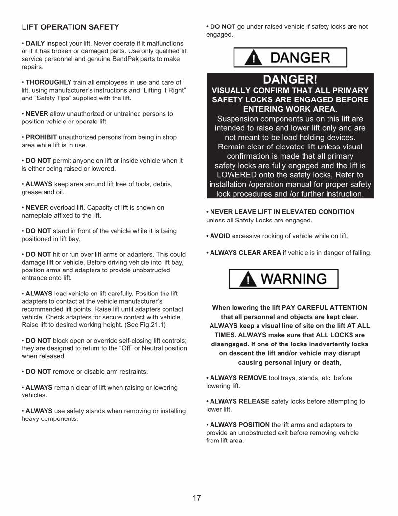
• DO NOT go under raised vehicle if safety locks are not engaged.
• NEVER LEAVE LIFT IN ELEVATED CONDITION unless all Safety Locks are engaged.
• AVOID excessive rocking of vehicle while on lift.
• ALWAYS CLEAR AREA if vehicle is in danger of falling.
When lowering the lift PAY CAREFUL ATTENTION that all personnel and objects are kept clear.
ALWAYS keep a visual line of site on the lift AT ALL TIMES. ALWAYS make sure that ALL LOCKS are
disengaged. If one of the locks inadvertently locks on descent the lift and/or vehicle may disrupt
causing personal injury or death,
• ALWAYS REMOVE tool trays, stands, etc. before lowering lift.
• ALWAYS RELEASE safety locks before attempting to lower lift.
• ALWAYS POSITION the lift arms and adapters to provide an unobstructed exit before removing vehicle from lift area.
DANGER! VISUALLY CONFIRM THAT ALL PRIMARY SAFETY LOCKS ARE ENGAGED BEFORE
ENTERING WORK AREA.Suspension components us on this lift are
intended to raise and lower lift only and are not meant to be load holding devices.
Remain clear of elevated lift unless visual confirmation is made that all primary
safety locks are fully engaged and the lift is LOWERED onto the safety locks, Refer to
installation /operation manual for proper safety lock procedures and /or further instruction.

18
TO RAISE THE LIFT
1. Before Loading: Lift must be fully lowered and service bay cleared of all personnel before the vehicle is brought on lift with the arms (if used) set to the full drive-thru position.
2. Loading: Position arms under vehicle and position adapters at vehicle manufacturer’s recommended lift points. Use height extenders or optional frame-cradle adapters (if applicable) when necessary to ensure good contact. (See Fig 10.1)
3. Some vehicles may have the manufacturer's Service Garage Lift Point locations identified by triangle shape marks on the undercarriage (reference ANSI/SAE J2184-1992). Also, there may be a label located on the right front door jamb area showing specific vehicle lift points.
TYPICAL LIFTING POINTS
4. Position vehicle for proper weight distribution arms un-der vehicle to allow adapters /pads to contact at the manu-facturer’s recommended pick up points.
WARNING!To avoid personal injury and/or property damage, permit
only trained personnel to operate lift. After reviewing these instructions, get familiar with lift controls by
running the lift through a few cycles before loading vehicle on lift. Always lift the vehicle using all four adapters. NEVER raise just one end, one corner,
or one side of vehicle.
WARNING!Many specialty or modified vehicles cannot be raised
on a two-post frame engaging lift. Contact vehicle manufacturer for raising or jacking details.
Fig. 10.1

19
5. If the specific vehicle lift points are not identified, or if the vehicle has additional or uniquely positioned payload, have a qualified person calculate the vehicle center of gravity or have the vehicle center of gravity determined at a vehicle scale. Load the vehicle with the enter of gravity midway between adapters.
6. Set parking brake or use wheel chock to hold vehicle in position.
Make sure vehicle is neither front nor rear heavy and select the proper configuration for the vehicle to be lifted as shown below. Center of balance should be midway between adapters and centered over the lift.

20
7. Push the RAISE button or rotate the control switch on the power unit.
Important Note: Allow (2) seconds between motor starts.
Failure to comply may cause motor burnout.
8. Stop before making contact with vehicle. Check con-tact points. If required, slightly move arms or vehicle to allow restraint gear and pawl to mesh.
9. Raise vehicle until tires clear the floor.
10. Stop and check adapters for secure contact at vehicle manufacturer’s recommended lift points.
11. Continue to raise to desired height only if vehicle is secure on lift.
12. DO NOT go near or under a raised vehicle if all four adapters are not in secure contact with vehicle at vehicle manufacturer’s recommended lift points.
13. Repeat entire loading and raising procedures if required.
14. Lower lift onto safety locks.
• DO NOT enter work area or go under vehicle if safety locks are not engaged.
• CLEAR AREA if vehicle is in danger of falling.
• DO NOT position yourself between a wall and the lift. If the vehicle falls in that direction, you may be severely injured.
• Before attempting to lift pickup trucks or other truck frame vehicles, be sure that:
t Vehicle frame is strong enough to support its weight and has not been weakened by modification or corrosion.
t Vehicle individual axle weight does not exceed one-half lift capacity.
t Adapters are in secure contact with frame at vehicle manufacturers recommended lift points.
t Vehicle is stable on lift and neither front nor “tail” heavy. WHILE USING LIFT
• Avoid excessive rocking of vehicle while on lift.
• Always use safety stands as needed or when removing or installing heavy components.
DANGER! VISUALLY CONFIRM THAT ALL PRIMARY SAFETY LOCKS ARE ENGAGED BEFORE
ENTERING WORK AREA.Suspension components us on this lift are
intended to raise and lower lift only and are not meant to be load holding devices.
Remain clear of elevated lift unless visual confirmation is made that all primary
safety locks are fully engaged and the lift is LOWERED onto the safety locks, Refer to
installation /operation manual for proper safety lock procedures and /or further instruction.

21
TO LOWER THE LIFT
1. Remove all tools or other objects from the lift area.
2. Raise lift off safety locks. Make sure you raise the lift by at least two inches to allow adequate clearance for the locks to clear.
3. Confirm safety lock is in unlocked position.
4. Push LOWERING valve handle to lower. Do not override self-closing lift controls.
5. Remain clear of lift when lowering vehicle. Observe pinch point warning decals.
6. Remove adapters from under vehicle and arms to full drive-thru position before moving vehicle.
7. If lift is not operating properly, DO NOT use until adjustment or repairs are made by qualified lift service personnel.
MAINTENANCE INSTRUCTIONS
• Always keep bolts tight. Check periodically.
• Always keep lift components clean.
• Always if oil leakage is observed, call local service representative.
• Always if electrical problems develop, call local service representative.
• Always replace ALL FAULTY PARTS before lift is put back into operation.
• Daily: Make a visual inspection of ALL MOVING PARTS and check for excessive signs of wear.• Daily: Check Safety Locks to ensure they are in good operating condition.
• Daily: Check pivot points and hinges for wear. Replace worn parts as required with genuine BendPak parts.
• Daily: Inspect adapters for damage or excessive wear. Replace as required with genuine BendPak parts.
• Weekly: Lubricate any rollers with general purpose oil or WD-40. Lubricate arm Hinge Pins with grease.
• Weekly: Check bolts and pins to ensure proper mounting.
• Monthly: Lubricate locking latch shafts. Push latch handle several times for oil to penetrate pivot points.
• Semi-Annually: Check fluid level of lift power unit and refill if required per lift installation instructions.• Replace all caution, warning or safety related decals on the lift if unable to read or missing. Reorder labels from BendPak.
• Refer to ANSI/ALI ALOIM booklet for periodic inspection checklist and maintenance log sheet.
CAUTION!If you are not completely familiar with automotive lift maintenance procedures; STOP: Contact factory for
instructions. To avoid personal injury, permit only qualified personnel to perform maintenance on this
equipment.
WARNING!When lowering the lift PAY CAREFUL ATTENTION
that all personnel and objects are kept clear. ALWAYS keep a visual line of site on the lift AT ALL
TIMES. ALWAYS make sure that ALL LOCKS are disengaged. If one of the locks inadvertently locks
on descent the lift and/or vehicle may disrupt causing personal injury or death.

22
Safe Lift OperationAutomotive and truck lifts are critical to the operation and profitability of your business. The safe use of this and other lifts in your shop is critical in preventing employee injuries and damage to customer’s vehicles. By operating lifts safely you can ensure that your shop is profitable, productive and safe.Safe operation of automotive lifts requires that only trained employees should be allowed to use the lift.
TRAINING SHOULD INCLUDE, BUT NOT LIMITED TO:tProper positioning of the vehicle on the runway. (See manufacturers minimize wheel base loading requirements.)
tUse of the operating controls.
tUnderstanding the lift capacity.
tProper use of jack stands or other load supporting devices.
tProper use, understanding and visual identification of safety lock devices and their operation.
tReviewing the safety rules.
tProper housekeeping procedures (lift area should be free of grease, oil, tools, equipment, trash, and other debris)
tA daily inspection of the lift should be completed prior to its use. Safety devices, operating controls, lift arms and other critical parts should be inspected prior to using the lift.
tAll maintenance and repairs of the lift should be completed by following the manufacturer’s requirements. Lift repair parts should meet or exceed OEM specifications. Repairs should only be completed by a qualified lift technician.
tThe vehicle manufacturer’s recommendations should be used for spotting and lifting the vehicle.
LIFT OPERATION SAFETY
t It is important that you know the load limit. Be careful that you do not overload the lift . If you are unsure what the load limit is, check the data plate found on one of the lift columns or contact the manufacturer.
tThe center of gravity should be followed closely to what the manufacturer recommends.
tAlways make sure you have proper overhead clearance. Additionally, check that attachments, (vehicle signs, campers, antennas, etc.) are not in the way.
tBe sure that prior to the vehicle being raised, the doors, trunk, and hood are closed securely.
tPrior to being raised, make sure there is no one standing closer than six feet from the lift.
tAfter positioning the vehicle on the lift runways, set the emergency brake, make sure the ignition is off, the doors are closed, overhead obstructions are cleared, and the transmission is in neutral.
tDouble check that the automatic chock devices are in position and then when the lift is raised, observe the chocks. tPut pads or adapters in the right position under the contact points that have been recommended.
tThe lift should be raised just until the vehicle’s wheels are about one foot off the ground. If contact with the vehicle is uneven or it appears that the vehicle is not sitting secure, carefully lower the lift and readjust.
tAlways consider potential problems that might cause a vehicle to slip, i.e., heavy cargo, undercoating, etc.
tPay attention when walking under a vehicle that is up on the hydraulic lift.

tDO NOT leave the controls while the lift is still in motion.
tDO NOT stand directly in front of the vehicle or in the bay when vehicle is being loaded or driven into position.
tDO NOT Go near vehicle or attempt to work on the vehicle when being raised or lowered.
t REMAIN CLEAR of lift when raising or lowering vehicle.
tDO NOT rock the vehicle while on the lift or remove any heavy component from vehicle that may cause excessive weight shift.
tDO NOT lower the vehicle until people, materials, and tools are clear.
tALWAYS ENSURE that the safeties are engaged and lowered on to the safety ladders before any attempt is made to work on or near vehicle.
tSome vehicle maintenance and repair activities may cause the vehicle to shift. Follow the manufacturer’s guidelines when performing these operations. The use of jack stands or alternate lift points may be required when completing some repairs.
tREAD AND UNDERSTAND all safety warning procedures before operating lift.
tKEEP HANDS AND FEET CLEAR. Remove hands and feet from any moving parts. Keep feet clear of lift when lowering. Avoid pinch points.
tONLY TRAINED OPERATORS should operate this lift. All non-trained personnel should be kept away from work area. Never let non-trained personnel come in contact with, or operate lift.
tUSE LIFT CORRECTLY. Use lift in the proper manner. Never use lifting adapters other than what is approved by the manufacturer.
tDO NOT override self-closing lift controls.
tCLEAR AREA if vehicle is on danger of falling.
tSTAY ALERT. Watch what you are doing. Use common sense. Be aware.
tCHECK FOR DAMAGED PARTS. Check for alignment of moving parts, breakage of parts or any condition that may affect its operation. Do not use lift if any component is broken or damaged.
tNEVER remove safety related components from the lift. Do not use lift if safety related components are damaged or missing.
tWhen the lift is being lowered, make sure everyone is standing at least six feet away.
tBe sure there are no jacks, tools, equipment, left under the lift before lowering.
tAlways lower the vehicle down slowly and smoothly.
23

24

25

26
LIFT WILL NOT RAISE
POSSIBLE CAUSE1. Air in oil, (1,2,8,13)2. Cylinder binding, (9)3. Cylinder leaks internally, (9)4. Motor run backward under pressure, (11)5. Lowering valve leaks, (3,4,6,10,11)6. Motor runs backwards, (7,14,11)7. Pump damaged, (10,11)8. Pump won’t prime, (1,8,13,14,3,12,10,11)9. Relief valve leaks, (10,11)10. Voltage to motor incorrect, (7,14,11)
REMEDY INSTRUCTION1. Check for proper oil level. . . . . . . . . . . . . . . . . . . . . . . . . . The oil level should be up to the bleed screw in the reservoir with the lift all the way down.
2. Bleed cylinders. . . . . . . . . . . . . . . . . . . . . . . . . . . . . . . . . . See Installation Manual
3. Flush- Release valve to get rid of. . . . . . . . . . . . . . . . . . . . . Hold release handle down and start unit allowing possible contamination it to run for 15 seconds.
4. Dirty oil. . . . . . . . . . . . . . . . . . . . . . . . . . . . .. . . . . . . . . . . . Replace oil with clean Dexron ATF.
5. Tighten all fasteners. . . . . . . . . . . . . . . . . . . . . . . . . . . . . . . Tighten fasteners to recommended torques.
6. Check for free movement of release. . . . . . . . . . . . . . . . . . . If handle does not move freely, replace bracket or handle assembly. 7. Check motor is wired correctly. . . . . . . . . . . . . . . . . . . . . . . Compare wiring of motor to electrical diagram on drawing.
8. Oil seal damaged or cocked . . . . . . . . . . . . . . . . . . . . . . . . .Replace oil seal around pump shaft.
9. See Installation Manual . . . . . . . . . . . . . . . . . . . . . . . . . . . . Consult Lift Manufacturer.
10. Replace with new part . . . . . . . . . . . . . . . . . . . . . . . . . . . . . Replace with new part.
11. Return unit for repair . . . . . . . . . . . . . . . . . . . . . . . . . . . . . . Return unit for repair.
12. Check pump-mounting bolts . . . . . . . . . . . . . . . . . . . . . . . . Bolts should be 15 to 18 ft. lbs.
13. Inlet screen clogged . . . . . . . . . . . . . . . . . . . . . . . . . . . . . . Clean inlet screen or replace.
14. Check wall outlet voltages and wiring . . . . . . . . . . . . . . . . . .Make sure unit and wall outlet are wired properly.

MOTOR WILL NOT RUN
POSSIBLE CAUSE1. Fuse blown, (5,2,1,3,4)2. Limit switch burned out, (1,2,3,4)3. Microswitch burned out, (1,2,3,4)4. Motor burned out, (1,2,3,4,6)5. Voltage to motor incorrect, (2,1,8)
REMEDY INSTRUCTION1. Check for correct voltage . . . . . . . . . . . . . . . . . . . . . . . . . . .Compare supply voltage with voltage on motor name tag. Check that the wire is sized correctly. N.E.C. table 310-12 requires AWG 10 for 25 Amps. 2. Check motor is wired correctly . . . . . . . . . . . . . . . . . . . . . . .Compare wiring of motor to electrical diagram on drawing.
3. Don’t use extension cords . . . . . . . . . . . . . . . . . . . . . . . . . . According to N.E.C. : “ The size of the conductors… should be such that the voltage drop would not exceed 3% to the farthest outlet for power…” Do not run motor at 115 VAC – damage to the motor will occur.
4. Replace with new part . . . . . . . . . . . . . . . . . . . . . . . . . . . . .Replace with new part.
5. Reset circuit breaker/fuse . . . . . . . . . . . . . . . . . . . . . . . . . .Reset circuit breaker/fuse.
6. Return unit for repair . . . . . . . . . . . . . . . . . . . . . . . . . . . . . Return unit for repair.
7. See Installation Manual . . . . . . . . . . . . . . . . . . . . . . . . . . . .See Installation Manual.
8. Check wall outlet voltage and wiring . . . . . . . . . . . . . . . . . . Make sure unit and wall outlet is wired properly. Motor must run at 208/230 VAC.
LIFT LOWERS SLOWLY OR NOT AT ALL
POSSIBLE CAUSE1. Cylinders binding, (1)2. Release valve clogged, (5,4,2,3)3. Pressure fitting too long, (6)
REMEDY INSTRUCTION1. See Installation Manual . . . . . . . . . . . . . . . . . . . . . . . . . . . . Consult Lift Manufacturer.
2. Replace with new part . . . . . . . . . . . . . . . . . . . . . . . . . . . . .Replace with new part.
3. Return for repair . . . . . . . . . . . . . . . . . . . . . . . . . . . . . . . . . Return for repair.4. Check oil. . . . . . . . . . . . . . . . . . . . . . . . . . . . . . . . . . . . . . Use clean 10-WT hydraulic oil or Dexron-III automatic transmission fluid only. If ATF is contaminated, replace with clean ATF and clean entire system.
5. Clean release valve . . . . . . . . . . . . . . . . . . . . . . . . . . . . . . . . Wash release valve in solvent and blow out with air.
6. Replace fitting with short thread lead . . . . . . . . . . . . . . . . . . . Replace fitting with short thread lead.
27

28
WILL NOT RAISE LOADED LIFT
POSSIBLE CAUSE1. Air in oil, (1,2,3,4)2. Cylinder binding, (5)3. Cylinder leaks internally, (5)4. Lift overloaded, (6,5)5. Lowering valve leaks, (7,8,1,5,9)6. Motor runs backwards, (10,12,9)7. Pump damaged, (5,9)8. Pump won’t prime, (1,2,3,4,5,11,9)9. Relief valve leaks, (8,5,9)10. Voltage to motor incorrect, (10,12,5)
REMEDY INSTRUCTION1. Check oil level . . . . . . . . . . . . . . . . . . . . . . . . . . . . . . . . . . The oil level should be up to the bleed screw in the reservoir with the lift all the way down.
2. Check/Tighten inlet tubes . . . . . . . . . . . . . . . . . . . . . . . . . . Replace inlet hose assembly.
3. Oil seal damaged or cocked . . . . . . . . . . . . . . . . . . . . . . . . Replace oil seal and install.
4. Bleed cylinders . . . . . . . . . . . . . . . . . . . . . . . . . . . . . See Installation Manual.
5. See Installation Manual . . . . . . . . . . . . . . . . . . . . . . . . . . . . Consult Lift Manufacturer.
6. Check vehicle weight . . . . . . . . . . . . . . . . . . . . . . . . . . . . . Compare weight of vehicle to weight limit of the lift.
7. Flush release valve . . . . . . . . . . . . . . . . . . . . . . . . . . . . . Hold release handle down and start unit allowing it to run for 15 seconds.
8. Replace with new part . . . . . . . . . . . . . . . . . . . . . . . . . . . . . Replace with new part.
9. Return unit for repair . . . . . . . . . . . . . . . . . . . . . . . . . . . . . . Return unit for repair.
10. Check motor is wired correctly . . . . . . . . . . . . . . . . . . . . . . . Compare wiring of motor to electrical diagram on power unit drawing.
11. Inlet screen clogged . . . . . . . . . . . . . . . . . . . . . . . . . . . . . . Clean inlet screen or replace.
12. Check wall outlet voltage and wiring . . . . . . . . . . . . . . . . . . .Make sure unit and wall outlet is wired properly.

29
LIFT WILL NOT STAY UPPOSSIBLE CAUSE1. Air in oil, (1,2,3)2. Check valve leaks, (6)3. Cylinders leak internally, (7)4. Lowering valve leaks, (4,5,1,7,6)5. Leaking fittings, (8)
REMEDY INSTRUCTION1. Check oil level . . . . . . . . . . . . . . . . . . . . . . . . . . . . . . . . . . . .The oil level should be up to the bleed screw in the reservoir with the lift all the way down.
2. Oil seal damaged and cocked . . . . . . . . . . . . . . . . . . . . . . . . Replace oil seal around pump shaft.
3. Bleed cylinder . . . . . . . . . . . . . . . . . . . . . . . . . . . . . . . . . . . . Refer to Installation Manual.
4. Flush release valve . . . . . . . . . . . . . . . . . . . . . . . . . . . . . . . . Hold release handle down and start unit allowing it to run for 15 seconds.
5. Replace with new valve . . . . . . . . . . . . . . . . . . . . . . . . . . . . . Replace with new valve.
6. Return unit for repair . . . . . . . . . . . . . . . . . . . . . . . . . . . . . . . Return unit for repair.
7. See Installation Manual . . . . . . . . . . . . . . . . . . . . . . . . . . . . . Consult Lift Manufacturer.
8. Check complete hydraulic system for leaks. . . . . . . . . . . . . . . Tighten all hydraulics fittings and inspects all hoses.

30
DIM
ENSI
ON
S A
RE IN
MM
☺
1
2
3
REV
ISIO
NRE
VD
ESC
RIPT
ION
DA
TEED
ITED
BY
ECO
#G
UPD
ATE
D B
OM
REV
ISIO
N09
/22/
2011
TM00
483
HUP
DA
TED
BO
M R
EVIS
ION
S02
/17/
2012
TM00
490
JUP
DA
TED
BO
M R
EVIS
ION
05/1
7/20
12TM
0052
1
ITEM
NO
PART
NUM
BER
DES
CRI
PTIO
NQ
TYRE
V1
5245
128
MD
-6XP
LIF
T SU
PERS
TRUC
TURE
1F
252
1526
3M
D-6
XP P
OW
ER U
NIT
STA
ND
ASS
EMBL
Y1
A3
5250
128
MD
-6XP
PA
RTS
BOX
1F
SHE
ET 1
OF
2
REV
DW
G.
NO
.
ASIZETITLE
:
NA
ME
DA
TE
CHE
CKE
D
DRA
WN
SIZE
:
MA
TERI
AL:
J
1645
LEM
ON
WO
OD
DR.
SAN
TA P
AUL
A, C
A 9
3060
PRO
PRIE
TARY
AN
D C
ON
FIDE
NTIA
LTH
E IN
FORM
ATIO
N C
ON
TAIN
ED IN
THI
S D
RAW
ING
IS
THE
SOLE
PRO
PERT
Y O
F BE
NDP
AK
INC
. AN
Y RE
PRO
DUC
TION
IN P
ART
OR
AS
A W
HOLE
WITH
OUT
TH
E W
RITT
EN P
ERM
ISSI
ON
OF
BEN
DPA
K IN
C. I
S PR
OHI
BITE
D.
NO
TE: U
NLE
SS O
THER
WIS
E SP
ECIF
IED.
TM
5260
169
MD
-6XP
REC
EIV
ED L
IFT
VER
B
--- ---
02/1
9/20
09
DO
NO
T SC
ALE
DRA
WIN
G
1:20
SCA
LE:
THIR
D A
NG
LE P
ROJE
CTIO
N
MT
05/3
0/20
12
5250
128
& 5
2152
63 S
HIP
PED
ON
SEP
ARA
TE P
ALL
ET1.
SEE
SHIP
PIN
G IN
STRU
CTIO
NS
FOR
FIN
AL
PAC
KAG
ING
2.
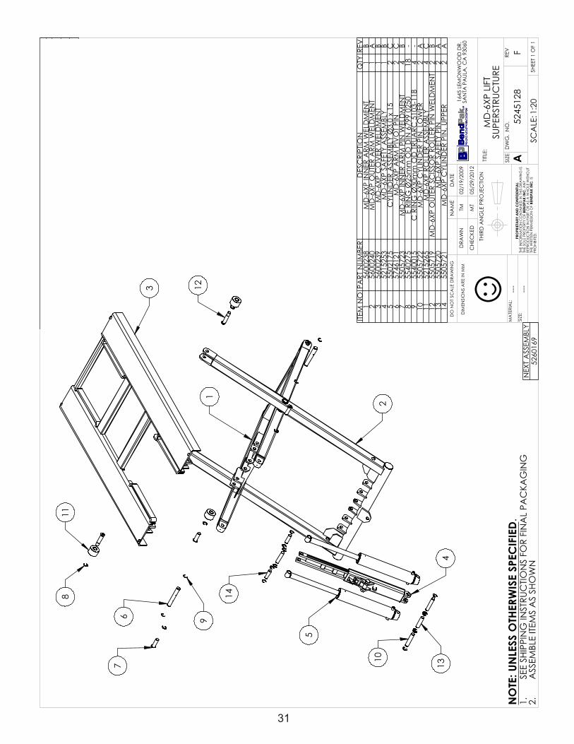
31
DIM
ENSI
ON
S A
RE IN
MM
☺
11
3 121
2
413
10
14
5
67
9
8
REV
ISIO
NRE
VD
ESC
RIPT
ION
DA
TEED
ITED
BY
ECO
#D
UPD
ATE
D B
OM
REV
ISIO
NS
09/2
2/20
11TM
0048
3E
UPD
ATE
D B
OM
REV
ISIO
N02
/17/
2012
TM00
490
FUP
DA
TED
BO
M R
EVIS
ION
05/1
6/20
12TM
0052
1
NEX
T A
SSEM
BLY
5260
169
ITEM
NO
PART
NUM
BER
DES
CRI
PTIO
NQ
TYRE
V1
5600
238
MD
-6XP
INN
ER A
RM W
ELD
MEN
T1
B2
5600
240
MD
-6XP
OUT
ER A
RM W
ELD
MEN
T1
A3
5600
239
MD
-6XP
CO
VER
WEL
DM
ENT
1B
452
1525
3M
D-6
XP S
AFE
TY A
SSEM
BLY
1B
555
0217
5C
YLIN
DER
ASS
EMBL
Y Ø
3.0
x 15
2C
657
4612
1M
D-6
XP A
RM P
IVO
T PI
N2
C7
5505
723
MD
-6XP
INN
ER A
RM P
IN W
ELD
MEN
T4
B8
5540
275
E RI
NG
Ø25
mm
OD
DIN
679
9 02
5018
-9
5540
015
C R
ING
Ø30
mm
OD
TRU
ARC
510
3-11
84
-10
5505
722
MD
-6XP
CYL
IND
ER P
IN, L
OW
ER2
A11
5215
265
MD
-6XP
RO
LLER
ASS
EMBL
Y4
C12
5505
719
MD
-6XP
OUT
ER S
CIS
SOR
ROLL
ER P
IN W
ELD
MEN
T2
B13
5505
720
MD
-6XP
SA
FETY
PIN
2A
1455
0572
1M
D-6
XP C
YLIN
DER
PIN
, UPP
ER2
A
SHE
ET 1
OF
1
REV
DW
G.
NO
.
ASIZETITLE
:
NA
ME
DA
TE
CHE
CKE
D
DRA
WN
SIZE
:
MA
TERI
AL:
F
1645
LEM
ON
WO
OD
DR.
SAN
TA P
AUL
A, C
A 9
3060
PRO
PRIE
TARY
AN
D C
ON
FIDE
NTIA
LTH
E IN
FORM
ATIO
N C
ON
TAIN
ED IN
THI
S D
RAW
ING
IS
THE
SOLE
PRO
PERT
Y O
F BE
NDP
AK
INC
. AN
Y RE
PRO
DUC
TION
IN P
ART
OR
AS
A W
HOLE
WITH
OUT
TH
E W
RITT
EN P
ERM
ISSI
ON
OF
BEN
DPA
K IN
C. I
S PR
OHI
BITE
D.
NO
TE: U
NLE
SS O
THER
WIS
E SP
ECIF
IED.
TM
5245
128
MD
-6XP
LIF
T SU
PERS
TRUC
TURE
--- ---
02/1
9/20
09
DO
NO
T SC
ALE
DRA
WIN
G
1:20
SCA
LE:
THIR
D A
NG
LE P
ROJE
CTIO
N
MT
05/2
9/20
12
SEE
SHIP
PIN
G IN
STRU
CTIO
NS
FOR
FIN
AL
PAC
KAG
ING
1.A
SSEM
BLE
ITEM
S A
S SH
OW
N2.
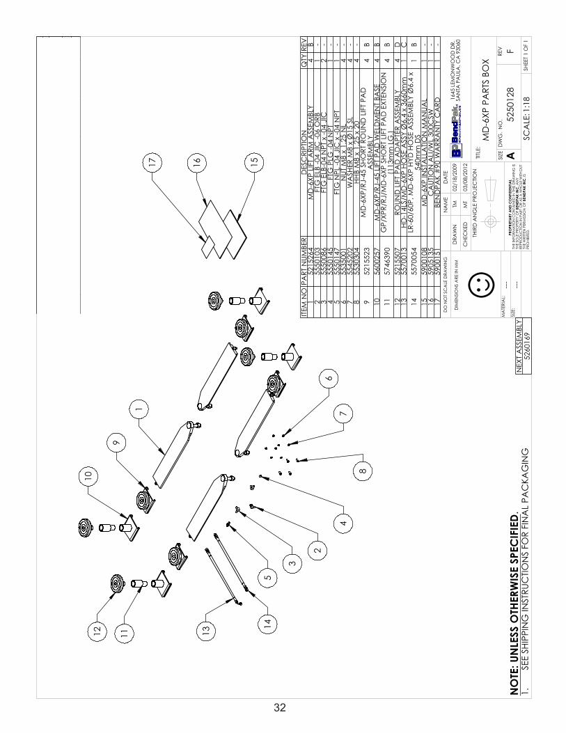
32
DIM
ENSI
ON
S A
RE IN
MM
☺
12
9
1
8
67
4
3
2
14
13
5
11
17 16 15
10
REV
ISIO
NRE
VD
ESC
RIPT
ION
DA
TEED
ITED
BY
ECO
#D
REPL
AC
ED 5
2152
50 W
ITH 5
2155
07, R
EPLA
CED
52
1525
2 W
ITH 5
2155
2305
/26/
2011
TM00
463
EUP
DA
TED
BO
M R
EVIS
ION
11/0
9/20
11TM
0048
3F
UPD
ATE
D B
OM
REV
ISIO
NS
02/1
6/20
12TM
0049
0
NEX
T A
SSEM
BLY
5260
169
ITEM
NO
PART
NUM
BER
DES
CRI
PTIO
NQ
TYRE
V1
5215
264
MD
-6XP
LIF
T A
RM A
SSEM
BLY
4B
255
5010
3FT
G E
LB -0
4 JI
C -0
6 O
RB1
-3
5550
086
FTG
ELB
-04
NPT
x -0
4 JI
C2
-4
5550
145
FTG
PLG
-04
NPT
1-
555
5014
7FT
G N
PL -0
4 JI
C x
-04
NPT
1-
655
3500
1N
UT M
8 x
1.25
NL
4-
755
4520
2W
ASH
ER M
8 x
Ø15
SL
4-
855
3030
4H
HB
M8
x 1.
25 x
20
4-
952
1552
3M
D-6
XP/R
J-45
SH
ORT
RO
UND
LIF
T PA
D
ASS
EMBL
Y4
B10
5600
257
MD
-6XP
/RJ-
45 L
IFT
PAD
WEL
DM
ENT
BASE
4B
1157
4639
0G
P/XP
R/RJ
/MD
-6XP
SH
ORT
LIF
T PA
D E
XTEN
SIO
N
(113
mm
LG
.)4
B12
5215
507
ROUN
D L
IFT
PAD
AD
APT
ER A
SSEM
BLY
4D
1355
7001
3H
D-1
4LS/
MD
-6XP
HO
SE A
SSY
Ø6.
4 x
3660
mm
1C
1455
7005
4LR
-60/
60P,
MD
-6XP
HYD
HO
SE A
SSEM
BLY
Ø6.
4 x
540m
m D
S1
B15
5900
108
MD
-6XP
INST
ALL
ATIO
N M
AN
UAL
1-
1659
0513
5C
AUT
ION
ALI
/WL
300C
SW1
-17
5900
151
BEN
DPA
K #
90 W
ARR
AN
TY C
ARD
1-
SHE
ET 1
OF
1
REV
DW
G.
NO
.
ASIZETITLE
:
NA
ME
DA
TE
CHE
CKE
D
DRA
WN
SIZE
:
MA
TERI
AL:
F
1645
LEM
ON
WO
OD
DR.
SAN
TA P
AUL
A, C
A 9
3060
PRO
PRIE
TARY
AN
D C
ON
FIDE
NTIA
LTH
E IN
FORM
ATIO
N C
ON
TAIN
ED IN
THI
S D
RAW
ING
IS
THE
SOLE
PRO
PERT
Y O
F BE
NDP
AK
INC
. AN
Y RE
PRO
DUC
TION
IN P
ART
OR
AS
A W
HOLE
WITH
OUT
TH
E W
RITT
EN P
ERM
ISSI
ON
OF
BEN
DPA
K IN
C. I
S PR
OHI
BITE
D.
NO
TE: U
NLE
SS O
THER
WIS
E SP
ECIF
IED.
TM
5250
128
MD
-6XP
PA
RTS
BOX
--- ---
02/1
8/20
09
DO
NO
T SC
ALE
DRA
WIN
G
1:18
SCA
LE:
THIR
D A
NG
LE P
ROJE
CTIO
N
MT
03/0
8/20
12
SEE
SHIP
PIN
G IN
STRU
CTIO
NS
FOR
FIN
AL
PAC
KAG
ING
1.

33
MAINTENANCE RECORDS
_____________________________________________________________________
_____________________________________________________________________
_____________________________________________________________________
_____________________________________________________________________
_____________________________________________________________________
_____________________________________________________________________
_____________________________________________________________________
_____________________________________________________________________
_____________________________________________________________________
_____________________________________________________________________
_____________________________________________________________________
_____________________________________________________________________
_____________________________________________________________________
_____________________________________________________________________
_____________________________________________________________________
_____________________________________________________________________
_____________________________________________________________________
_____________________________________________________________________
_____________________________________________________________________
_____________________________________________________________________

34
MAINTENANCE RECORDS
_____________________________________________________________________
_____________________________________________________________________
_____________________________________________________________________
_____________________________________________________________________
_____________________________________________________________________
_____________________________________________________________________
_____________________________________________________________________
_____________________________________________________________________
_____________________________________________________________________
_____________________________________________________________________
_____________________________________________________________________
_____________________________________________________________________
_____________________________________________________________________
_____________________________________________________________________
_____________________________________________________________________
_____________________________________________________________________
_____________________________________________________________________
_____________________________________________________________________
_____________________________________________________________________
_____________________________________________________________________

35This page intentionally left blank.

For Parts Or ServiceContact:
BendPak Inc. / Ranger Products1645 Lemonwood Dr.
Santa Paula, CA. 93060
Tel: 1-805-933-9970Toll Free: 1-800-253-2363
Fax: 1-805-933-9160
www.bendpak.comp/n 5900108