pluto ethernet gateway manual - abb ltd · - removed ftp, tftp and web servers. - removed login on...
TRANSCRIPT

Original instructions
English v3C 2TLC172285M0203_C
PLUTO Ethernet Gateway
User Manual
GATE-EIP EtherNet/IP™GATE-EC EtherCAT®
GATE-S3 Sercos IIIGATE-PN PROFINET®
GATE-MT Modbus TCP
2 2TLC172285M0203_C
Reference:
[REF x] TextREF 1 Pluto Operating instructions, Hardware
Pluto Programming manualPluto Gateway Manual
2TLC172001Mxxyy_z2TLC172002Mxxyy_z2TLC172009Mxxyy_z
Trademark Notices:
EtherNet/IP is a registered trademark by ODVA.For more information see www.odva.com.
EtherCAT is a registered trademark and patented technology,licensed by Beckhoff Automation GmbH, Germany.For more information see www.ethercat.org.
Sercos is a registered trademark by Sercos International and Sercos North America.For more information see www.sercos.com.
PROFINET is a trademark by PROFIBUS and PROFINET International (PI)For more information see www.profibus.com.
Modbus TCP is according to the Modbus Organization.For more information see www.modbus.org.

3 2TLC172285M0203_C
Table of contents:1 Version information ..................................................................................................... 82 Cyber security disclaimer ............................................................................................ 93 Cyber security deployment guideline......................................................................... 103.1 Network installation ................................................................................................... 103.2 Limit network connections ......................................................................................... 103.3 Pluto remote handling ............................................................................................... 123.4 PC port usage (only local access) ............................................................................. 124 General ..................................................................................................................... 134.1 Installation................................................................................................................. 134.1.1 Mounting ................................................................................................................... 134.1.2 Electrical installation ................................................................................................. 144.2 Maintenance and service .......................................................................................... 154.3 GATE-E2 replacement .............................................................................................. 155 Hardware .................................................................................................................. 165.1 Connection, indication and switches ......................................................................... 165.1.1 Top side .................................................................................................................... 165.1.1.1 ABB StatusBus terminal ............................................................................................ 175.1.1.2 Pluto bus terminal ..................................................................................................... 175.1.1.3 Configuration switch .................................................................................................. 185.1.2 Front panel................................................................................................................ 185.1.2.1 “K” button .................................................................................................................. 185.1.2.2 PC port ..................................................................................................................... 185.1.2.3 Indicators (LED) ........................................................................................................ 195.1.2.3.1 Gateway status ......................................................................................................... 195.1.2.3.2 Ethernet protocol status ............................................................................................ 205.1.2.3.3 Ethernet link status ................................................................................................... 205.1.3 Bottom side ............................................................................................................... 205.1.3.1 Ethernet port 1 .......................................................................................................... 215.1.3.2 Ethernet port 2 .......................................................................................................... 215.1.3.3 Power terminal .......................................................................................................... 216 Common configuration .............................................................................................. 226.1 Pluto bus ................................................................................................................... 226.1.1 Connection................................................................................................................ 226.1.2 Baud rate detection ................................................................................................... 226.1.3 Status indication........................................................................................................ 226.1.4 Gateway node number .............................................................................................. 226.1.4.1 Set by PLC................................................................................................................ 226.1.4.2 Set by DIP switch ...................................................................................................... 236.1.4.3 Set by terminal command ......................................................................................... 236.2 IP address assignment.............................................................................................. 236.3 Network services....................................................................................................... 246.3.1 ICMP Ping command ................................................................................................ 246.3.2 Industry Ethernet Protocol ......................................................................................... 246.3.3 Remote server .......................................................................................................... 246.4 Verification of configuration ....................................................................................... 256.5 Terminal commands ................................................................................................. 266.5.1 bg – gateway network status ..................................................................................... 266.5.2 bs – Pluto bus status ................................................................................................. 266.5.3 bc – gateway configuration status ............................................................................ 276.5.4 bw – industry Ethernet protocol status ...................................................................... 286.5.5 v – version information .............................................................................................. 286.5.6 h – help ..................................................................................................................... 296.5.7 exit – exit .................................................................................................................. 306.5.8 View Pluto data ......................................................................................................... 306.5.9 View gateway data .................................................................................................... 30

4 2TLC172285M0203_C
6.5.10 pl/pkl – Download Pluto project ................................................................................. 316.6 Terminal commands (only PC port) ........................................................................... 316.6.1 time – get run time .................................................................................................... 316.6.2 cn – change gateway node number .......................................................................... 316.6.3 addc – clear additional data configuration ................................................................. 316.6.4 adds – configure additional data ............................................................................... 326.6.5 ctp – configure “Data to Pluto”................................................................................... 326.6.6 ipaddr – change IP address ...................................................................................... 336.6.7 remote – enable/disable remote operation of Pluto system ....................................... 336.6.8 name – change the device station name (GATE-PN) ................................................ 346.6.9 reset – restart the unit ............................................................................................... 346.6.10 sys – firmware update of the unit .............................................................................. 346.6.11 def – restore factory settings ..................................................................................... 356.6.12 dout – disconnect remote clients ............................................................................... 356.6.13 test – test command .................................................................................................. 356.7 Silent commands ...................................................................................................... 356.8 Firmware update ....................................................................................................... 366.8.1 Firmware update via PC port using Pluto Manager ................................................... 366.8.2 Firmware update via PC port..................................................................................... 387 GATE-EIP, EtherNet/IP ............................................................................................. 407.1 Ethernet Connection ................................................................................................. 407.2 IP address configuration ........................................................................................... 407.3 Status indication........................................................................................................ 407.3.1 Module Status ........................................................................................................... 417.3.2 Network Status ......................................................................................................... 417.4 Service port information ............................................................................................ 427.5 Rockwell integration .................................................................................................. 438 GATE-EC, EtherCAT ................................................................................................ 488.1 Ethernet Connection ................................................................................................. 488.2 IP address configuration ........................................................................................... 488.3 Status indication........................................................................................................ 488.3.1 Link/Activity ............................................................................................................... 488.3.2 RUN Status ............................................................................................................... 498.3.3 Error Status ............................................................................................................... 498.3.4 LED handling ............................................................................................................ 508.4 ABB AC500 integration ............................................................................................. 518.4.1 Device repository and XML file .................................................................................. 518.4.2 Hardware .................................................................................................................. 528.4.3 CM_579 Master ........................................................................................................ 528.4.4 Gate_EC_Pluto_Gateway ......................................................................................... 538.4.5 Startup parameters ................................................................................................... 548.4.6 I/O mapping list ......................................................................................................... 568.5 Beckhoff TwinCAT integration ................................................................................... 578.5.1 Add device description file ........................................................................................ 578.5.2 Scan system for the device ....................................................................................... 578.5.3 Firmware update ....................................................................................................... 579 GATE-S3, Sercos III ................................................................................................. 609.1 Ethernet Connection ................................................................................................. 609.2 IP address configuration ........................................................................................... 609.3 Status indication........................................................................................................ 619.4 Service port information ............................................................................................ 619.5 Bosch-Rexroth IndraWorks integration ...................................................................... 629.5.1 Add device description file ........................................................................................ 629.5.2 Scan system for the device ....................................................................................... 639.5.3 Gateway configuration .............................................................................................. 6410 GATE-PN, PROFINET .............................................................................................. 6510.1 Description file .......................................................................................................... 65

5 2TLC172285M0203_C
10.2 Data format ............................................................................................................... 6510.3 Ethernet Connection ................................................................................................. 6510.4 IP address configuration ........................................................................................... 6610.5 Status indication........................................................................................................ 6710.5.1 SF (System Failure) .................................................................................................. 6710.5.2 BF (Bus Failure) ........................................................................................................ 6710.6 Service port information ............................................................................................ 6710.7 ABB AC500 implementation ...................................................................................... 6810.7.1 Device repository and XML file .................................................................................. 6810.7.2 Hardware .................................................................................................................. 6910.7.2.1 Adding objects .......................................................................................................... 6910.7.2.2 Configuring objects ................................................................................................... 7010.7.2.3 Configuring Gate-PN ................................................................................................. 7010.7.3 PROFINET name ...................................................................................................... 7110.7.4 Assigning variable names ......................................................................................... 7210.8 Siemens integration .................................................................................................. 7310.8.1 Install GSD XML file .................................................................................................. 7310.8.2 Add the device to the PROFINET network ................................................................ 7410.8.2.1 PROFINET name and IP address ............................................................................. 7410.8.2.2 IO Cycle .................................................................................................................... 7510.8.2.3 Module parameters of the Head module ................................................................... 7510.8.2.4 Device view ............................................................................................................... 7610.8.2.4.1 Adding modules under the Head module .................................................................. 7610.8.2.4.2 Module parameters of modules under the Head module ........................................... 7710.8.2.4.3 Addressing of in- and out-data .................................................................................. 7810.8.2.5 Tag list ...................................................................................................................... 7910.8.2.5.1 Example of Pluto A20 family mapping ....................................................................... 8011 GATE-MT, Modbus TCP ........................................................................................... 8111.1 Ethernet Connection ................................................................................................. 8111.2 IP address configuration ........................................................................................... 8111.3 Status indication........................................................................................................ 8111.3.1 RUN .......................................................................................................................... 8211.3.2 ERR .......................................................................................................................... 8211.4 Service port information ............................................................................................ 8211.5 Integration and configuration ..................................................................................... 8211.6 ABB AC500 integration ............................................................................................. 8311.6.1 Hardware configuration ............................................................................................. 8311.6.2 CoDeSys implementation .......................................................................................... 8411.6.2.1 Structured Flow Chart Implementation ...................................................................... 8411.6.2.1.1 Variables ................................................................................................................... 8411.6.2.1.2 Structured Flow chart steps ...................................................................................... 8611.6.2.1.3 Init step ..................................................................................................................... 8711.6.2.1.4 Configuration step, Write ........................................................................................... 8711.6.2.1.5 Pluto units online, Read ............................................................................................ 8711.6.2.1.6 Global Data, Read .................................................................................................... 8811.6.2.1.7 Additional Data, Read ............................................................................................... 8811.6.2.1.8 Packets to Pluto, Write .............................................................................................. 8811.6.2.2 Task configuration ..................................................................................................... 8912 Data to/from Pluto ..................................................................................................... 9012.1 Pluto Status .............................................................................................................. 9012.2 Global Data from Pluto .............................................................................................. 9012.3 Additional Data from Pluto ........................................................................................ 9112.3.1 Layout of additional data ........................................................................................... 9112.3.1.1 User defined blocks .................................................................................................. 9112.3.1.2 Standard blocks ........................................................................................................ 9212.3.2 Programming in Pluto PLC ........................................................................................ 9512.3.2.1 Function block library ................................................................................................ 95

6 2TLC172285M0203_C
12.3.2.2 Use of the function blocks ......................................................................................... 9512.3.2.3 Example of usage in Pluto program .......................................................................... 9612.4 Data to Pluto ............................................................................................................. 9812.4.1 Enable bit .................................................................................................................. 9812.4.2 Cyclic transmission time ............................................................................................ 9812.4.3 Timeout time ............................................................................................................. 9812.5 In PLUTO - Reception of external data from gateway ............................................... 9812.5.1 Set up in PLUTO for reception .................................................................................. 9812.5.2 Addressing of external data in Pluto .......................................................................... 9912.5.3 Connection of external variables in PLC code ......................................................... 10012.5.3.1 Function block ”Ext_Sig” ......................................................................................... 10012.5.3.2 Function block ”Ext_Val” ......................................................................................... 10012.5.3.3 Function block ”ExtVarBlock” .................................................................................. 10013 Technical data ........................................................................................................ 10213.1 Protocol specific data .............................................................................................. 10213.2 Common data ......................................................................................................... 10314 Appendix A, gateway registers. ............................................................................... 10414.1 Gateway registers 0 - … ......................................................................................... 10414.2 Gateway registers 100 - … ..................................................................................... 10514.3 Gateway register 200 - … ....................................................................................... 10614.4 Gateway register 300 - … ....................................................................................... 10714.5 Gateway register 400 - … ....................................................................................... 10814.6 Gateway register 500 - … ....................................................................................... 10814.7 Gateway register 600 - … ....................................................................................... 10915 Appendix B, object description EtherNet/IP ............................................................. 11015.1 Definitions ............................................................................................................... 11015.2 Identity Object (01HEX - 1 Instance) ........................................................................... 11115.3 Message Router Object (02HEX) .............................................................................. 11115.4 Assembly Object (04HEX – 5 Instances) ................................................................... 11215.5 Connection Manager Object (06HEX) ........................................................................ 11415.6 TCP Object (F5HEX - 1 Instance) ............................................................................... 11515.7 Ethernet Link Object (F6HEX - 1 Instance) ................................................................. 11615.8 Application Object (64HEX - 32 Instances) ................................................................. 11716 Appendix C, object description EtherCAT ............................................................... 12016.1 PDO mapping ......................................................................................................... 12016.1.1 Input mapping ......................................................................................................... 12016.1.1.1 Pluto status (0x1A00) .............................................................................................. 12016.1.1.2 Pluto global 0 – 7 (0x1A01) ..................................................................................... 12016.1.1.3 Pluto global 8 – 15 (0x1A02) ................................................................................... 12016.1.1.4 Pluto global 16 – 23 (0x1A03) ................................................................................. 12016.1.1.5 Pluto global 24 – 31 (0x1A04) ................................................................................. 12116.1.1.6 Additional data 0 – 7 (0x1A05) ................................................................................ 12116.1.1.7 Additional data 8 – 15 (0x1A06) .............................................................................. 12116.1.1.8 Additional data 16 – 23 (0x1A07) ............................................................................ 12216.1.1.9 Additional data 24 – 31 (0x1A08) ............................................................................ 12216.1.2 Output mapping ...................................................................................................... 12216.1.2.1 Data to Pluto packet 1 (0x1600) .............................................................................. 12216.1.2.2 Data to Pluto packet 1 (0x1601) .............................................................................. 12216.1.2.3 Data to Pluto packet 3 (0x1602) .............................................................................. 12316.1.2.4 Data to Pluto packet 4 (0x1603) .............................................................................. 12316.2 SDO mapping ......................................................................................................... 12316.2.1 Pluto global data (0x2100) ...................................................................................... 12316.2.2 Additional data (0x2101) ......................................................................................... 12416.2.3 Pluto status (0x2120) .............................................................................................. 12516.2.4 Data to Pluto (0x220y) ............................................................................................ 12516.2.5 Configuration of additional data (0x23zz) ................................................................ 12516.2.6 Configuration of Data to Pluto (0x2320) .................................................................. 125
7 2TLC172285M0203_C
16.2.7 Configuration gateway node number (0x2321) ........................................................ 12517 Appendix D, object description Sercos III ................................................................ 12617.1 Standard Sercos IDN supported by the gateway ..................................................... 12617.2 IDN for gateway configuration ................................................................................. 12918 Appendix E, object description PROFINET ............................................................. 13219 Appendix F, object description Modbus TCP ........................................................... 14919.1 Port number ............................................................................................................ 14919.2 Unit Identifier ........................................................................................................... 14919.3 Access functions ..................................................................................................... 14919.4 Data format ............................................................................................................. 14919.5 Data to Pluto ........................................................................................................... 15019.6 Gateway Configuration............................................................................................ 15019.7 Data to/from Pluto ................................................................................................... 15219.8 Data from Pluto ....................................................................................................... 153
8 2TLC172285M0203_C
1 Version informationThis document is valid for:
Hardware version : 2.3
Firmware version- GATE-EIP : 2.15- GATE-EC : 1.3- GATE-S3 : 1.3- GATE-PN : 1.2- GATE-MT : Currently not supported.
Updates in 2TLC172285M0203_C:- Removed FTP, TFTP and web servers.- Removed login on telnet server and renamed the server to remote server.- Updated cyber security deployment guideline (3).- Updated the terminal command information (6.5).- Updated firmware update handling (6.8).- Added PLC download via gateway using Pluto Manager (6.5.10).

9 2TLC172285M0203_C
2 Cyber security disclaimerThis gateway product is designed to be connected and to communicate information and data via anetwork interface, which should be connected to a secure network. It is your sole responsibility toprovide and continuously ensure a secure connection between the product and your network orany other network (as the case may be) and to establish and maintain appropriate measures (suchas but not limited to the installation of firewalls, application of authentication measures, encryptionof data, installation of antivirus programs, etc.) to protect the product, the network, its system andinterfaces against any kind of security breaches, unauthorized access, interference, intrusion,leakage and/or theft of data or information. ABB Ltd and its affiliates are not liable for damagesand/or losses related to such security breaches, unauthorized access, interference, intrusion,leakage and/or theft of data or information.
Although ABB provides functionality testing on the products and updates that we release, youshould institute your own testing program for any product updates or other major system updates(to include but not limited to code changes, configuration file changes, third party software updatesor patches, hardware change out, etc.) to ensure that the security measures that you haveimplemented have not been compromised and system functionality in your environment is asexpected.
For more information/contact regarding ABB cyber security see:
http://www.abb.com/cybersecurity
10 2TLC172285M0203_C
3 Cyber security deployment guideline
3.1 Network installation
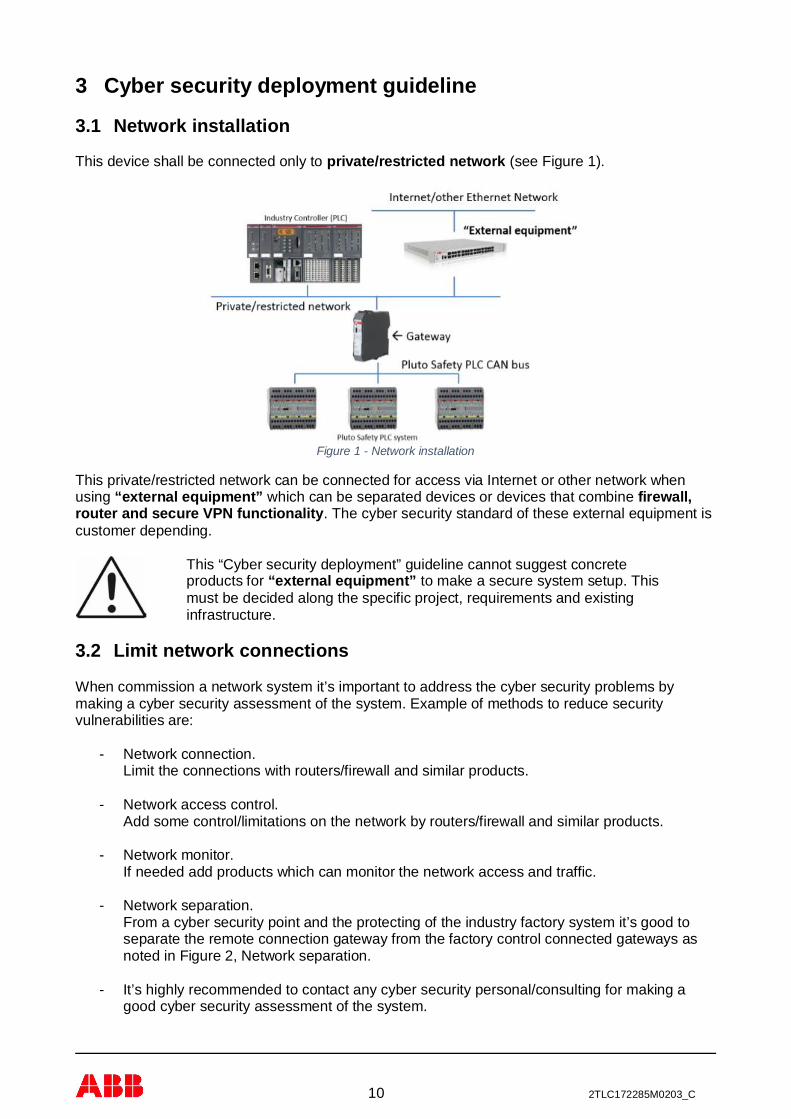
This device shall be connected only to private/restricted network (see Figure 1).
Figure 1 - Network installation
This private/restricted network can be connected for access via Internet or other network whenusing “external equipment” which can be separated devices or devices that combine firewall,router and secure VPN functionality. The cyber security standard of these external equipment iscustomer depending.
This “Cyber security deployment” guideline cannot suggest concreteproducts for “external equipment” to make a secure system setup. Thismust be decided along the specific project, requirements and existinginfrastructure.
3.2 Limit network connections
When commission a network system it’s important to address the cyber security problems bymaking a cyber security assessment of the system. Example of methods to reduce securityvulnerabilities are:
- Network connection.Limit the connections with routers/firewall and similar products.
- Network access control.Add some control/limitations on the network by routers/firewall and similar products.
- Network monitor.If needed add products which can monitor the network access and traffic.
- Network separation.From a cyber security point and the protecting of the industry factory system it’s good toseparate the remote connection gateway from the factory control connected gateways asnoted in Figure 2, Network separation.
- It’s highly recommended to contact any cyber security personal/consulting for making agood cyber security assessment of the system.

11 2TLC172285M0203_C
Figure 2, Network separation.

12 2TLC172285M0203_C
3.3 Pluto remote handling
The gateway product has together with Pluto Manager the possibility to make remote monitor andcontrol of Pluto safety PLC system. By default this service is disabled in the gateway, but it can beenabled with the “remote” command (see 6.6.12) via the PC port (see 5.1.2.2) on the device.
The Pluto remote monitor and control is handled by the remote server (see 6.3.3) with its cybersecurity limitations (see 6.3.3). The connection to the remote server don’t have anyauthentication and the traffic is not encrypted.
For Pluto control (Pluto PLC download and configuration) a limited access control is implementedby using the device “K” button. When the device get a commands related to any Pluto controlcommand it will request authentication by an operator at site who shall pressing the “K” button onthe device. This will give some protection against unintentional re-configuration of the Plutosystem.
All commands related to configuration of the gateway itself is not supported via the remote server,e.g. only supported via the PC port.
When enable Pluto remote monitor and control handling the device shall be installed according tochapter 3.1.
The Pluto remote monitor and control behavior is depending on good network conductivity on boththe Pluto bus network and the Ethernet network.
3.4 PC port usage (only local access)
The PC port (see 5.1.2.2) shall only be used for local terminal access to thedevice and are not designed for any external access handling.

13 2TLC172285M0203_C
4 GeneralThe Ethernet gateways are a series of gateways for different industry Ethernet protocols. Eachmodel is dedicated to specific industry Ethernet protocol. The following list gives a summary of theexisting industry Ethernet gateways:
- GATE-EIP (2TLA020071R9000) for EtherNet/IP.- GATE-EC (2TLA020071R9100) for EtherCAT.- GATE-S3 (2TLA020071R9200) for Sercos III.- GATE-PN (2TLA020071R9300) for PROFINET.- GATE-MT (2TLA020071R9400) for Modbus TCP.
In addition to the industry Ethernet protocol each device also has support remote server (telnet).
The Pluto Safety PLC system and the gateways GATE-P1/P2, -D1/D2, -C1/C2 and -E1/E2 aredescribed in the manual [REF 1].
Figure 3 – Pluto system with gateway
4.1 Installation
The device shall be installed according to the information within this manual.
4.1.1 Mounting
The device shall be mounted on a 35 mm DIN rail.
For ventilation requirement the device shall be mounted vertical with minimum 20 mm free spaceon top/bottom side, see Figure 4.

14 2TLC172285M0203_C
20 mm
20 mmFigure 4 - Installation
The device shall be installed indoors and its enclosure is IP20. The device shall therefore beinstalled in cabinet for proper environmental protection, see technical data chapter 13.2.
4.1.2 Electrical installation
The device is designed for applications which fulfil IEC-EN 60204-1.
The device is powered by 24 VDC (4.8 W/0.2 A) and it has internal fuse (2 A) protection. Externalfuse (type C characteristic) shall be used to protect the electrical wiring (according to UL 2550 VW-1 or equivalent) to the device and the value of the fuse is depending on the installation (example 6A type C characteristic using minimum 0.75 mm2 wiring), see Figure 5.
Enclosure and terminals are able to reach temperatures above 60 °C inambient temperatures of up to 55 °C. The electrical wiring (cables) shalltherefore meet the specification of minimum 65 °C.Boîtier et bornes sont capables d'atteindre des températures supérieures à60 °C à des températures ambiantes jusqu'à 55 °C. Le câblage électrique(câbles) doit donc répondre à la spécification minimale de 65 °C.
Figure 5 - 24 VDC installation
24 VDC
0V +V
Fuse (example 6 A)
DIN rail grounding

15 2TLC172285M0203_C
The device shall be installed in a system (the complete system) using a common ground systeme.g. proper potential equalization is necessary.
When mounted on the DIN rail the device ground (0V) is connected via a capacitor to the DIN rail.Therefore the DIN rail shall be connected to the system ground, see Figure 5.
The user can install a disconnecting device if needed on the power line; or use an external fusewhich is approved to be used as disconnecting device. The device also has detachable terminalblocks which can be used as a disconnection device.
4.2 Maintenance and service
The device has no requirements regarding maintenance or service.
4.3 GATE-E2 replacement
The GATE-EIP, GATE-PN and GATE-MT are functional replacements for GATE-E2 within thedifferent industry Ethernet protocols with the following notes,
- Power terminal plug is changed, see 5.1.1.2.- Pluto bus terminal plug is changed, see 5.1.1.2.- There is no support for GATE-E2 local data request/response service object/function.- There is no support for GATE-E2 pass through service object/function.- There is no support for GATE-E2 binary server.

16 2TLC172285M0203_C
5 HardwareThe Ethernet gateway is housed in a 22.5 mm enclosure with 35 mm DIN rail mounting.
Top side
Front panel DIN rail mounting/connection
Bottom sideFigure 6 - Gateway side description
5.1 Connection, indication and switches
The gateway has connections, indications and switches on four sides (see Figure 6).
- Two connections and one configuration switch on the top side see 5.1.1.- One connection and several indicators on the front panel, see 5.1.2.- Three connections on the bottom side see 5.1.3.- One connection to DIN rail, see 4.1.
5.1.1 Top side
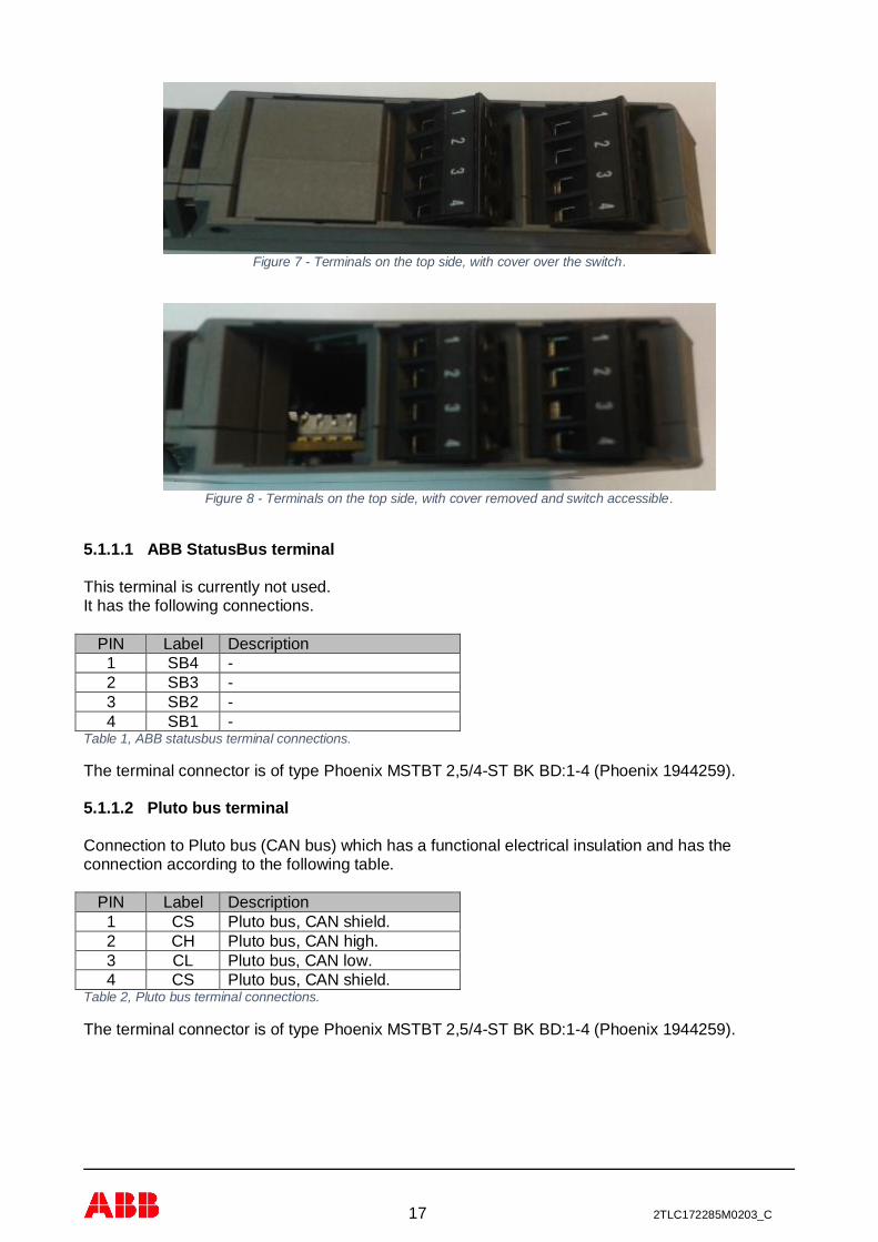
The following connectors are positioned on the gateways top side (in order from front to back), seeFigure 7 and Figure 8:
- ABB StatusBus terminal.- Pluto bus terminal.- Switch setting (behind cover).
17 2TLC172285M0203_C
Figure 7 - Terminals on the top side, with cover over the switch.
Figure 8 - Terminals on the top side, with cover removed and switch accessible.
5.1.1.1 ABB StatusBus terminal
This terminal is currently not used.It has the following connections.
PIN Label Description1 SB4 -2 SB3 -3 SB2 -4 SB1 -
Table 1, ABB statusbus terminal connections.
The terminal connector is of type Phoenix MSTBT 2,5/4-ST BK BD:1-4 (Phoenix 1944259).
5.1.1.2 Pluto bus terminal
Connection to Pluto bus (CAN bus) which has a functional electrical insulation and has theconnection according to the following table.
PIN Label Description1 CS Pluto bus, CAN shield.2 CH Pluto bus, CAN high.3 CL Pluto bus, CAN low.4 CS Pluto bus, CAN shield.
Table 2, Pluto bus terminal connections.
The terminal connector is of type Phoenix MSTBT 2,5/4-ST BK BD:1-4 (Phoenix 1944259).
18 2TLC172285M0203_C
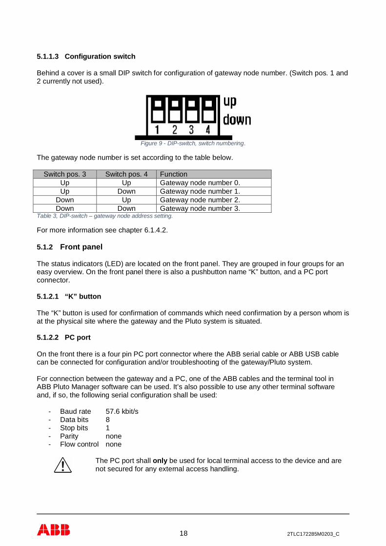
5.1.1.3 Configuration switch
Behind a cover is a small DIP switch for configuration of gateway node number. (Switch pos. 1 and2 currently not used).
Figure 9 - DIP-switch, switch numbering.
The gateway node number is set according to the table below.
Switch pos. 3 Switch pos. 4 FunctionUp Up Gateway node number 0.Up Down Gateway node number 1.
Down Up Gateway node number 2.Down Down Gateway node number 3.
Table 3, DIP-switch – gateway node address setting.
For more information see chapter 6.1.4.2.
5.1.2 Front panel
The status indicators (LED) are located on the front panel. They are grouped in four groups for aneasy overview. On the front panel there is also a pushbutton name “K” button, and a PC portconnector.
5.1.2.1 “K” button
The “K” button is used for confirmation of commands which need confirmation by a person whom isat the physical site where the gateway and the Pluto system is situated.
5.1.2.2 PC port
On the front there is a four pin PC port connector where the ABB serial cable or ABB USB cablecan be connected for configuration and/or troubleshooting of the gateway/Pluto system.
For connection between the gateway and a PC, one of the ABB cables and the terminal tool inABB Pluto Manager software can be used. It’s also possible to use any other terminal softwareand, if so, the following serial configuration shall be used:
- Baud rate 57.6 kbit/s- Data bits 8- Stop bits 1- Parity none- Flow control none
The PC port shall only be used for local terminal access to the device and arenot secured for any external access handling.
19 2TLC172285M0203_C
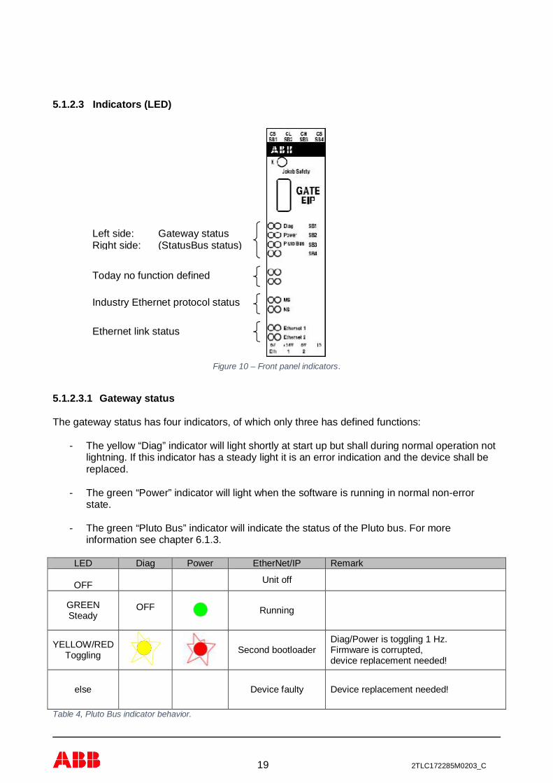
5.1.2.3 Indicators (LED)
Figure 10 – Front panel indicators.
5.1.2.3.1 Gateway status
The gateway status has four indicators, of which only three has defined functions:
- The yellow “Diag” indicator will light shortly at start up but shall during normal operation notlightning. If this indicator has a steady light it is an error indication and the device shall bereplaced.
- The green “Power” indicator will light when the software is running in normal non-errorstate.
- The green “Pluto Bus” indicator will indicate the status of the Pluto bus. For moreinformation see chapter 6.1.3.
LED Diag Power EtherNet/IP Remark
OFF Unit off
GREENSteady
OFF Running
YELLOW/REDToggling Second bootloader
Diag/Power is toggling 1 Hz.Firmware is corrupted,device replacement needed!
else Device faulty Device replacement needed!
Table 4, Pluto Bus indicator behavior.
Industry Ethernet protocol status
Today no function defined
Left side: Gateway statusRight side: (StatusBus status)
Ethernet link status

20 2TLC172285M0203_C
5.1.2.3.2 Ethernet protocol status
The Ethernet protocol status indicators are two combined red/green indicators giving the possibilityfor two status indications. Each Ethernet protocol has its own defined behavior on these indicatorsand the behavior is defined in the chapter for each protocol.
- EtherNet/IP, see chapter 7.3.- EtherCAT, see chapter 8.3.- Sercos III, see chapter 9.3.- PROFINET, see chapter 10.5.- Modbus TCP, see chapter 11.3.
5.1.2.3.3 Ethernet link status
The Ethernet link status is two combined yellow/green indicators giving the status for eachEthernet port (see connectors on bottom side chapter 0 and 5.1.3.2). Each color has the followingstatus information related the Ethernet port.
Yellow indicator Flashing light indicates Ethernet traffic on the port.E.g. no flashing indicates no Ethernet traffic on the port.
Green indicator Steady light indicates Ethernet connection.E.g. no light indicates no Ethernet connection.
Table 5, Ethernet link status indicator behavior.
For the green indicator the “Ethernet connection” only means there is a cable connection betweenthe gateway and the other Ethernet device (Ethernet switch, other device or PC). It is not anindication of data traffic; this is indicated by the Ethernet protocol status indicators.
For EtherCAT there is a different coding of the link status, see chapter 8.3.1.
5.1.3 Bottom side
The following connectors are positioned on the gateways bottom side (in order from front to back):
- Ethernet port 1 (EtherCAT this is the IN port)- Ethernet port 2 (EtherCAT this is the OUT port)- Power terminal
Figure 11 – Bottom side terminal connections.

21 2TLC172285M0203_C
5.1.3.1 Ethernet port 1
This is the first Ethernet port on the gateway and it shall be the main port to connect to thenetwork. For “daisy chain” connecting on EtherCAT this is the input connector.
Connection is standard RJ45 connector and the cable used shall be (minimum) according to Cat5eS/FTP (shielded cable).
5.1.3.2 Ethernet port 2
This is the second Ethernet port on the gateway and it shall be the secondary port to connect tothe network. For “daisy chain” connecting on EtherCAT this is the output connector.
Connection is standard RJ45 connector and the cable used shall be (minimum) according to Cat5eS/FTP (shielded cable).
5.1.3.3 Power terminal
The unit is powered with 24 VDC using this terminal connection 1 and 2.
On this terminal it is possible to connect an ABB IDFIX device for future use (has today nofunction).
Terminal Description1 0V2 +24VDC3 0V4 (IDFIX)
Table 6, 24 VDC power terminal connections.
The terminal connector is of type Phoenix MSTBT 2,5/4-ST BK BD:1-4 (Phoenix 1944259).
22 2TLC172285M0203_C
6 Common configurationThis chapter contains information about configuration which is common for all models of theEthernet gateways described in this manual.
6.1 Pluto bus
The Pluto bus is a CAN bus which means that the connection shall follow the common rules for allCAN buses. For more information see Pluto Safety PLC hardware manual [REF 1].
6.1.1 Connection
The connector for the Pluto bus is located on the top side of the enclosure (normal mounting).If the gateway is placed at the beginning or at the end of the bus line a 120 Ω terminating resistormust be mounted. For Pluto bus terminal connection see chapter 5.1.1.2.
6.1.2 Baud rate detection
The gateway will automatically detect the baud rate when there is traffic on the Pluto bus. Oncedetected, the baud rate setting will remain while there is traffic on the bus. If the traffic isinterrupted for 5 seconds or more the automatic baud rate detection will be restarted.
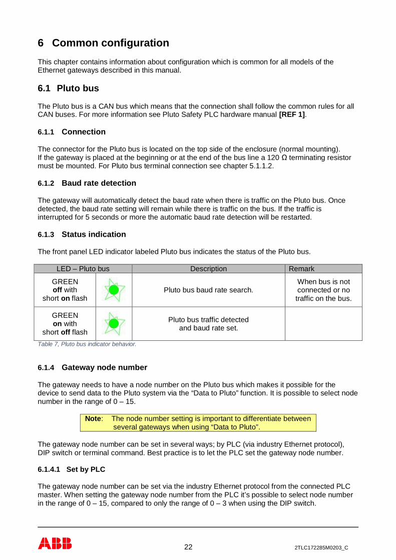
6.1.3 Status indication
The front panel LED indicator labeled Pluto bus indicates the status of the Pluto bus.
LED – Pluto bus Description Remark
GREENoff with
short on flashPluto bus baud rate search.
When bus is notconnected or notraffic on the bus.
GREENon with
short off flash
Pluto bus traffic detectedand baud rate set.
Table 7, Pluto bus indicator behavior.
6.1.4 Gateway node number
The gateway needs to have a node number on the Pluto bus which makes it possible for thedevice to send data to the Pluto system via the “Data to Pluto” function. It is possible to select nodenumber in the range of 0 – 15.
Note: The node number setting is important to differentiate betweenseveral gateways when using “Data to Pluto”.
The gateway node number can be set in several ways; by PLC (via industry Ethernet protocol),DIP switch or terminal command. Best practice is to let the PLC set the gateway node number.
6.1.4.1 Set by PLC
The gateway node number can be set via the industry Ethernet protocol from the connected PLCmaster. When setting the gateway node number from the PLC it’s possible to select node numberin the range of 0 – 15, compared to only the range of 0 – 3 when using the DIP switch.

23 2TLC172285M0203_C
The configuration parameter shall be set according to the table below. The default value is 0 whichmeans that the node number has been read from the DIP switch.
Value Function0 (default) Gateway node number from DIP switch.
1 Gateway node number 0.2 Gateway node number 1.3 Gateway node number 2.4 Gateway node number 3.5 Gateway node number 4.6 Gateway node number 5.7 Gateway node number 6.8 Gateway node number 7.9 Gateway node number 8.
10 Gateway node number 9.11 Gateway node number 10.12 Gateway node number 11.13 Gateway node number 12.14 Gateway node number 13.15 Gateway node number 14.16 Gateway node number 15.
Table 8, Gateway node number selection via PLC.
Note: If the DIP switch is changed and the device is restarted the gateway will use the DIP switchnode number until it’s overwritten by the PLC.
6.1.4.2 Set by DIP switch
The gateway has a DIP switch where it is possible to set the node number of the unit to a valuebetween 0 – 3. The value of the DIP switch is only read at power on. For more information aboutthe DIP switch see chapter 5.1.1.3.
6.1.4.3 Set by terminal command
It is also possible to set the gateway node number via terminal command if no other ways arepossible to use. For more information see chapter 6.6.2.
6.2 IP address assignment
Each type of product will at delivery have a default IP address and IP address handling accordingto the device industry Ethernet protocols preferred setting, for more information see chapter for therelevant industry Ethernet protocol.
For some of the Ethernet gateways (GATE-EC and GATE-PN) there is no manual assignment ofthe IP address. In these systems the master PLC will assign IP address to the device duringcommissioning. For these devices the rest of this chapter has no meaning.
The IP address can be assigned and changed in several ways,- Static address.
- Via the industry Ethernet protocol if this is supported.- Via the PC port on the front panel (see chapter 5.1.2.2).
- DHCP address setting.- BOOTP address setting.

24 2TLC172285M0203_C
Normally many master units on the industry Ethernet protocol has some functions to handle andchange the device IP address when connected to the network. How to do this depends on the usedindustry controller and no deeper information regarding this can be given here.
The second best way is to connect a terminal program to the PC port on the front panel. Via thisinterface it is possible to view the current IP address setting with the “bw” command. The IPaddress can be change by using the “ipaddr” command, see chapter 6.6.6.
6.3 Network services
The Ethernet gateways have several Ethernet network services. These services are:
Service Default settingICMP Ping command. Enabled
Can’t be disabled.The device industry Ethernet Protocol. Enabled
Can’t be disabled.Remote server (telnet). Disabled
Can be enabled/disabled by the user.Table 9, Device network services.
For cyber security reasons the remote servers are disabled by default. If the user needs thefunctionality with of this services it can be enabled by the user using terminal commands, seechapter 6.6.7.
It’s important that the user before enabling any of the services read the relevant chapter for theservice to get knowledge in the service functionality and its cyber security limitations.
6.3.1 ICMP Ping command
The device will respond on any ICMP ping command which is sent to the device IP address. Thisservice is by default always enabled and can’t be disabled.
C:\>ping 192.168.0.100
Pinging 192.168.0.100 with 32 bytes of data:Reply from 192.168.0.100: bytes=32 time=2ms TTL=64Reply from 192.168.0.100: bytes=32 time=1ms TTL=64Reply from 192.168.0.100: bytes=32 time=1ms TTL=64Reply from 192.168.0.100: bytes=32 time=1ms TTL=64
Ping statistics for 192.168.0.100: Packets: Sent = 4, Received = 4, Lost = 0 (0% loss),Approximate round trip times in milli-seconds: Minimum = 1ms, Maximum = 2ms, Average = 1msC:\>
Figure 12 – Ping command.
6.3.2 Industry Ethernet Protocol
The industry Ethernet protocol is different for the different gateway models, but it is eitherEhterNet/IP, EtherCAT, Sercos III, PROFINET or Modbus TCP. One of these protocols will berunning on the device and can’t be disabled e.g. it will always be active for any connection.
6.3.3 Remote server
Cyber security is an important part when enabling this services, see chapter 2.

25 2TLC172285M0203_C
The remote server (telnet) is a network terminal interface similar to the PC port on the unit’s frontpanel with limited functionality. This gives the possibility to access the unit via the network forremote monitoring and remote control of Pluto system.
By default the remote server is disabled. If the user want to use the remote server and explorethis server on the network it can be enabled see chapter 6.6.7.
The remote server will listen on port number 50100 (default) and this can be changed when usingthe remote enable command (6.6.7).
When connecting to the remote server there is no login handling e.g. when open the connection tothe remote server the user have direct access to the commands provide via this server. Thecommands are a subset of the commands handled by the PC port terminal connection.
The remote server connection has a 10 minutes timeout with automatic disconnection it therehaven’t been any inputs.
Below is an example connection and a disconnection using the exit command to the remote server.Note that not login handling is used and to exit use the exit command at the terminal input.
************************************* EtherNet/IP gateway************************************* Name : GATE-EIP Article no : 2TLA020071R9000 Serial number: 4096************************************* Vendor ID : 950 Product code : 1100 Device type : 43************************************* Software ver : 2.15 Software date: 2016-12-28************************************* ABB AB, Jokab Safety www.abb.com/jokabsafety*************************************eip_gw> exit
Figure 13 – Remote server connection and disconnection.
As terminal program for the remote server use the Pluto Manager terminal window. If otherterminal program is used following settings,
- Use backspace key as control-H.- Local echo off.- Local line editing off.
Summary: Enable the remote server only if you need this function.Note no password is used for the connection!Data traffic to/from remote server is not encrypted, e.g. clear text.The remote server supports only one client connection.
6.4 Verification of configuration
Via the terminal commands (6.5) it is possible to check the status of the gateway and also to seewhich configuration the gateway has received from the master. For more information see the “bs”,“bw” and “bc” commands in chapter 6.5.

26 2TLC172285M0203_C
6.5 Terminal commands
Terminal commands can be used via a connection to the device PC port or via its remote server (ifenabled). With these terminal commands it’s possible to check and read the status of the unit andalso update the PLC program/configuration of the Pluto system.
Each gateway has a unique prompt on the terminal output:- GATE-EIP eip_gw>- GATE-S3 s3_gw>- GATE-EC ec_gw>- GATE-PN pn_gw>- GATE-MT mt_gw>
The prompt can be visible by pressing the ESC button. This will also end any current activecommands which can be active from previous usage of the PC port.
For handling the terminal interface the “h” command will always list all valid commands see 6.5.1.
6.5.1 bg – gateway network status
With this command it is possible to see which gateways are on the Pluto bus network. It’simportant that all gateways on the Pluto bus have unique node number.
In the example below the “bg” command finds a gateway node number 0, which is the gatewaywhere the command was given (connected). As gateway node number 1 there is a GATE-C2(CANopen), number 2 is GATE-E2 (Ethernet), number 3 is GATE-D2 (DeviceNet) and as gatewaynode number 6 there is a GATE-EIP (EtherNet/IP).
eip_gw> bg-------------------------------------Gateway 0 : Connected Gateway 8 : -Gateway 1 : GATE-C2 Gateway 9 : -Gateway 2 : GATE-E2 Gateway 10 : -Gateway 3 : GATE-D2 Gateway 11 : -Gateway 4 : - Gateway 12 : -Gateway 5 : - Gateway 13 : -Gateway 6 : GATE-EIP Gateway 14 : -Gateway 7 : - Gateway 15 : --------------------------------------eip_gw>
Figure 14 – Example gateway status (bg) command.
6.5.2 bs – Pluto bus status
With this command it’s possible to check the Pluto bus settings and status.
In the example below the device is operational on the Pluto bus as gateway node number 0 andthe current detected Pluto bus speed is 125 kbit/s. On the Pluto bus there is only one Pluto withnode number 10 active and it’s a Pluto B20 v2.
eip_gw> bs-------------------------------------Gateway node number: 0Pluto bus speed: 125 kbits-------------------------------------Pluto 0 : - Pluto 16 : -Pluto 1 : - Pluto 17 : -Pluto 2 : - Pluto 18 : -Pluto 3 : - Pluto 19 : -Pluto 4 : - Pluto 20 : -Pluto 5 : - Pluto 21 : -

27 2TLC172285M0203_C
Pluto 6 : - Pluto 22 : -Pluto 7 : - Pluto 23 : -Pluto 8 : - Pluto 24 : -Pluto 9 : - Pluto 25 : -Pluto 10 : B20 v2 Pluto 26 : -Pluto 11 : - Pluto 27 : -Pluto 12 : - Pluto 28 : -Pluto 13 : - Pluto 29 : -Pluto 14 : - Pluto 30 : -Pluto 15 : - Pluto 31 : --------------------------------------eip_gw>
Figure 15 – Example Pluto bus (bs) command.
6.5.3 bc – gateway configuration status
With this command it is possible to check and verify the configuration of the gateways applicationobjects for data to Pluto and the additional data configuration.
Configuration and changes of this data are normally done via the configuration functions on theindustry Ethernet protocol, but can also be done via terminal commands “ctp” see chapter 6.6.5,“addc” see chapter 6.6.3 and “adds” see chapter 6.6.4.
The example below of the “bc” command give that the “Data to Pluto” function is enabled for alldata packet area, industry Ethernet protocol write timeout is disabled (e.g. 0 ms) and the Pluto busupdate time is set to 100 ms.
For additional data there are three areas which has configuration. Area 0 is configured to receivedata from Pluto node 5 with data of type “Error Code” (IO-type number 100), area 1 to receive datafrom Pluto node 10 with data of type “USER:01” (IO-type number 1) and area 10 will receive datafrom Pluto node 10 with data of type “B46” (IO-type number 101).
eip_gw> bc-------------------------------------Data to Pluto Packet area 0: Enabled Packet area 1: Enabled Packet area 2: Enabled Packet area 3: Enabled EtherNet/IP write timeout: 0 ms Pluto bus update time: 100 ms-------------------------------------Additional data configuration Area Pluto IO-type | Area Pluto IO-type | Area Pluto IO-type | Area Pluto IO-type 0 5 ErrCode | 1 10 USER: 1 | 10 10 B46 |-------------------------------------eip_gw>
Figure 16 – Example gateway configuration status (bc) command.
For information about the IO-type see information. Table (and also chapter 12.3.1).
Short name Long name IO-type numberUSER:xx User block number xx. 1 – 99ErrCode Error Code. 100
B46 B46 I20-I47. 101ASIsaf2 AS-i node 16-31 safe inputs. 102ASI0103 AS-i node 1-3 standard input. 103ASI0407 AS-i node 4-7 standard input. 104ASI0811 AS-i node 8-11 standard input. 105ASI1215 AS-i node 12-15 standard input. 106ASI1619 AS-i node 16-19 standard input. 107
28 2TLC172285M0203_C
ASI2023 AS-i node 20-13 standard input. 108ASI2427 AS-i node 24-27 standard input. 109ASI2831 AS-i node 28-31 standard input. 110Global Pluto global. 111
B42 ASi B42 AS-i I20-I47. 112ASISaf1 AS-i node 1-15 safe input. 113
D45 D45 I20-I47. 114Table 10, IO-type information.
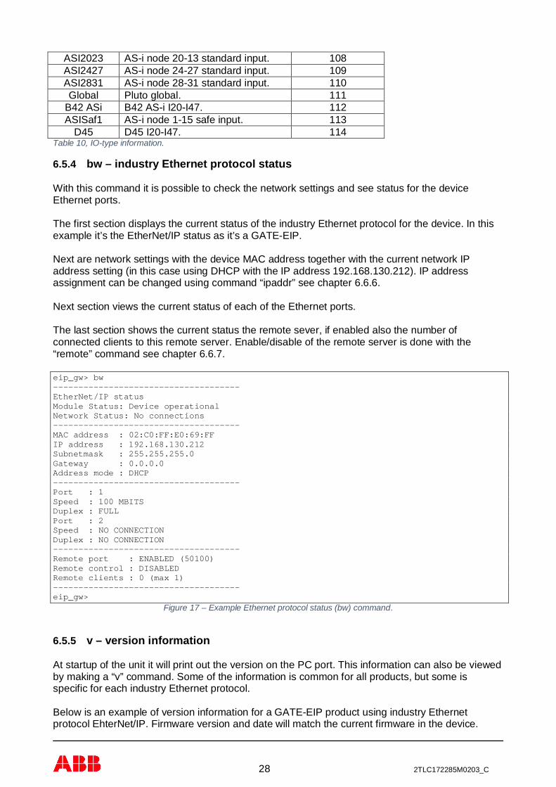
6.5.4 bw – industry Ethernet protocol status
With this command it is possible to check the network settings and see status for the deviceEthernet ports.
The first section displays the current status of the industry Ethernet protocol for the device. In thisexample it’s the EtherNet/IP status as it’s a GATE-EIP.
Next are network settings with the device MAC address together with the current network IPaddress setting (in this case using DHCP with the IP address 192.168.130.212). IP addressassignment can be changed using command “ipaddr” see chapter 6.6.6.
Next section views the current status of each of the Ethernet ports.
The last section shows the current status the remote sever, if enabled also the number ofconnected clients to this remote server. Enable/disable of the remote server is done with the“remote” command see chapter 6.6.7.
eip_gw> bw-------------------------------------EtherNet/IP statusModule Status: Device operationalNetwork Status: No connections-------------------------------------MAC address : 02:C0:FF:E0:69:FFIP address : 192.168.130.212Subnetmask : 255.255.255.0Gateway : 0.0.0.0Address mode : DHCP-------------------------------------Port : 1Speed : 100 MBITSDuplex : FULLPort : 2Speed : NO CONNECTIONDuplex : NO CONNECTION-------------------------------------Remote port : ENABLED (50100)Remote control : DISABLEDRemote clients : 0 (max 1)-------------------------------------eip_gw>
Figure 17 – Example Ethernet protocol status (bw) command.
6.5.5 v – version information
At startup of the unit it will print out the version on the PC port. This information can also be viewedby making a “v” command. Some of the information is common for all products, but some isspecific for each industry Ethernet protocol.
Below is an example of version information for a GATE-EIP product using industry Ethernetprotocol EhterNet/IP. Firmware version and date will match the current firmware in the device.

29 2TLC172285M0203_C
eip_gw> v************************************* EtherNet/IP gateway************************************* Name : GATE-EIP Article no : 2TLA020071R9000 Serial number: 105************************************* Vendor ID : 950 Product code : 1100 Device type : 43************************************* Firmware ver : 2.15 Firmware date: 2016-12-28************************************* ABB AB, Jokab Safety www.abb.com/jokabsafety*************************************eip_gw>
Figure 18 – Example device information (v) command.
6.5.6 h – help
With the online help command it’s possible to see which commands are available via the terminalconnection. Depending if the terminal connection is via the PC port or the remote server the list ofvalid command will be different. Commands can be entered with both capital and lower caseletters.
List of valid commands for both the PC port and the remote server connection,eip_gw> hI [Pluto node[.address]] read inputQ [Pluto node[.address]] read outputGM [Pluto node[.address]] read global memoryM [Pluto node[.address]] read memory bitR [Pluto node[.address]] read registerDR [Pluto node[.address]] read double registerS [Pluto node[.address]] read sequence stepSM [Pluto node[.address]] read system memory bitSR [Pluto node[.address]] read system registerSDR [Pluto node[.address]] read system double registerASIS [Pluto node[.address]] read AS-i safety inputASI [Pluto node[.address[.sub]]] read AS-i inputASQ [Pluto node[.address[.sub]]] read AS-i outputGW [gateway node.address] read gateway registerADD [gateway node[.area]] read gateway additional dataTO [gateway node[.area[.reg]]] read gateway data to PlutoBG view gateway nodes on Pluto busBS view Pluto nodes on Pluto busBC view gateway configurationBW view Ethernet configurationV view gateway version informationH view gateway help listEXIT remote disconnecteip_gw>
Figure 19 – List of valid commands (h) command for both PC port and remote server.
List of additional commands for PC port,...TIME view gateway uptimeCN change gateway node numberADDC clear gateway additional data configurationADDS change gateway additional data configurationCTP change gateway data to Pluto configurationIPADDR change gateway IP addressREMOTE enable remote monitoring of Pluto system

30 2TLC172285M0203_C
RESET restart gatewaySYS download new gateway firmwareDEF restore to the default factory settingsDOUT disconnect remote clientTEST run gateway production testeip_gw>
Figure 20 – List of additional commands (h) command valid only for PC port.
6.5.7 exit – exit
When connected to the remote server (6.3.3) the command “exit” will disconnect the connection.
6.5.8 View Pluto data
It’s possible to view Pluto data via the terminal command for checking data in a selected Pluto. Thelist below (from the help command) shows which data can be viewed,
I [Pluto node[.address]] read inputQ [Pluto node[.address]] read outputGM [Pluto node[.address]] read global memoryM [Pluto node[.address]] read memory bitR [Pluto node[.address]] read registerDR [Pluto node[.address]] read double registerS [Pluto node[.address]] read sequence stepSM [Pluto node[.address]] read system memory bitSR [Pluto node[.address]] read system registerSDR [Pluto node[.address]] read system double registerASIS [Pluto node[.address]] read AS-i safety inputASI [Pluto node[.address[.sub]]] read AS-i inputASQ [Pluto node[.address[.sub]]] read AS-i output
Figure 21 – List of valid view Pluto data commands (h) command.
The syntax for the parameters is “command[<Pluto node>[.<register[A/B]>[.subregister]]]” wherePluto node is the Pluto node number (0 – 31) and register is depending on command. For ASI andASQ command there is also a selection of A/B-slave plus an additional sub register.
When viewing a register it’s possible to make following commands,- Enter : step to next register (+1).- Backspace : step to previous register (-1).- ‘.’ : step to next register (+1).- ‘,’ : step to previous register (-1).- ‘h’ : switch between decimal and hexadecimal presentation.- ESC : exit the view command.
6.5.9 View gateway data
It’s possible to check the configuration of the gateway with several commands.
GW [gateway node.address] read gateway registerADD [gateway node[.area]] read gateway additional dataTO [gateway node[.area[.reg]]] read gateway data to Pluto
Figure 22 – List of valid view gateway data commands (h) command.
The gateway have most data viewed by “bs/bw/bc/add/to” commands accessible via registerreading using the “gw” command and some additional information see chapter 14. By using the“gw” command it’s also possible to read this data from other gateway via the Pluto bus.
The syntax for the “gw” command is “gw<gateway node>.<register address>” to read informationfrom any gateway node on the Pluto bus. To read information from the connected device it’spossible to use the “gw<register address>” command. E.g. if no or only one parameter is added tothe command it will view the information for the connected gateway register and with no parameter

31 2TLC172285M0203_C
starting at register 0. If the command has two parameters then the first is the gateway nodenumber (0 – 15) and the second it the register number. Explanation of the different registers withinthe gateway is listed in Appendix A, gateway registers. (Chapter 14).
When viewing a register it’s possible to make the following commands,- Enter : step to next register (+1).- Backspace : step to previous register (-1).- ‘.’ : step to next register (+1).- ‘,’ : step to previous register (-1).- ‘h’ : switch between decimal and hexadecimal presentation.- ESC : exit the view command.
The “add” and “to” commands will view the current value of additional data area for “add” commandand the current data to Pluto data with the “to” command. By these commands it’s then possible tosee what additional data the gateway receives from the Pluto bus, and which data will betransmitted on the Pluto bus.
6.5.10 pl/pkl – Download Pluto project
These command (pl and pkl) are command used by Pluto Manager to download Pluto project PLCvia the gateway to the connected Pluto system mainly using the gateway remote server (6.3.3)function.
When processed via the remote server the download process will prompt the operator to press thegateway or Pluto device “K” button to complete the project download. This to partly secure thedownload processing and also have a person on site which can overview the Pluto system.
For more information about download of Pluto PLC see Pluto Manager.
It’s possible to use these command direct form terminal window but it will not give the fullfunctionality of the download which is given by using PLC download via Pluto Manager. Thereforethese command are not visible via the help command.
6.6 Terminal commands (only PC port)
Commands describe in this section is only valid via the PC port for cyber security reason.
6.6.1 time – get run time
With the command “time” it is possible see run time of the gateway since last restart.
6.6.2 cn – change gateway node number
With the command “cn” it is possible to change the gateway node number on the Pluto bus. Thisshall normally not be needed because this configuration can normally be done via the industryEthernet protocol.
Below is an example when the gateway node number for the unit is set to node number 10.
eip_gw> cnGateway node number 0.Change node number in range 0-15 : 10Gateway node number changed to 10.eip_gw>
6.6.3 addc – clear additional data configuration
32 2TLC172285M0203_C
With the command “addc” it is possible to clear the current additional data configure, e.g. allconfiguration for the additional data elements like from which Pluto and which IO-type for all theadditional data areas will be cleared. The status of the set configuration can be checked using the“bc” command.
eip_gw> addcClear additional data configuration [Yes/No] ? yConfiguration cleared.eip_gw>
6.6.4 adds – configure additional data
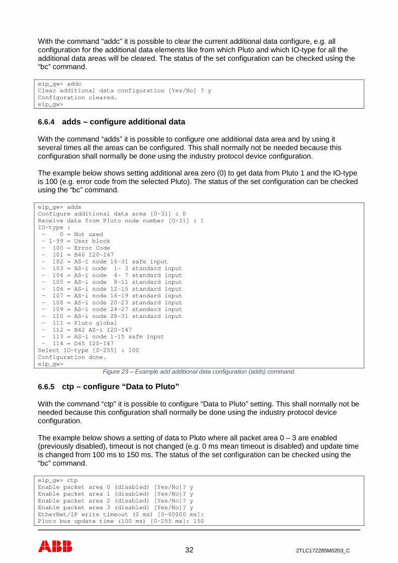
With the command “adds” it is possible to configure one additional data area and by using itseveral times all the areas can be configured. This shall normally not be needed because thisconfiguration shall normally be done using the industry protocol device configuration.
The example below shows setting additional area zero (0) to get data from Pluto 1 and the IO-typeis 100 (e.g. error code from the selected Pluto). The status of the set configuration can be checkedusing the “bc” command.
eip_gw> addsConfigure additional data area [0-31] : 0Receive data from Pluto node number [0-31] : 1IO-type : - 0 = Not used - 1-99 = User block - 100 = Error Code - 101 = B46 I20-I47 - 102 = AS-i node 16-31 safe input - 103 = AS-i node 1- 3 standard input - 104 = AS-i node 4- 7 standard input - 105 = AS-i node 8-11 standard input - 106 = AS-i node 12-15 standard input - 107 = AS-i node 16-19 standard input - 108 = AS-i node 20-23 standard input - 109 = AS-i node 24-27 standard input - 110 = AS-i node 28-31 standard input - 111 = Pluto global - 112 = B42 AS-i I20-I47 - 113 = AS-i node 1-15 safe input - 114 = D45 I20-I47Select IO-type [0-255] : 100Configuration done.eip_gw>
Figure 23 – Example add additional data configuration (adds) command.
6.6.5 ctp – configure “Data to Pluto”
With the command “ctp” it is possible to configure “Data to Pluto” setting. This shall normally not beneeded because this configuration shall normally be done using the industry protocol deviceconfiguration.
The example below shows a setting of data to Pluto where all packet area 0 – 3 are enabled(previously disabled), timeout is not changed (e.g. 0 ms mean timeout is disabled) and update timeis changed from 100 ms to 150 ms. The status of the set configuration can be checked using the“bc” command.
eip_gw> ctpEnable packet area 0 (disabled) [Yes/No]? yEnable packet area 1 (disabled) [Yes/No]? yEnable packet area 2 (disabled) [Yes/No]? yEnable packet area 3 (disabled) [Yes/No]? yEtherNet/IP write timeout (0 ms) [0-60000 ms]:Pluto bus update time (100 ms) [0-255 ms]: 150

33 2TLC172285M0203_C
Setting done.eip_gw>
Figure 24 – Example change “Data to Pluto” configuration (ctp) command.
6.6.6 ipaddr – change IP address
The “ipaddr” command is not implemented on EtherCAT and PROFINET as these protocols hasother protocol depending way to set the IP address of the device.
With the command “ipaddr” it’s possible to change the units IP address on the network. This IPaddress can be set as,
- Static, a fixed IP address set via terminal command.- DHCP, the unit will try to get IP address from DHCP server on the network.- BOOTP, the unit till try to get IP address using BOOTP.
Note: This will restart the gateway with the new settings!
Below is an example where the IP address is set to a static address 192.168.130.212 on a networkusing subnet mask of 255.255.255.0 and a default gateway of 0.0.0.0. Which setting to usedepends on the network where the unit will be connected. The unit will use the new IP addressafter a reset/power restart. Verify the setting by using the “bw” command after the unit has beenrestarted.
eip_gw> ipaddrAddress mode STATIC/BOOTP/DHCP (S/B/D) : s (STATIC)IP address : 192.168.130.212Subnetmask : 255.255.255.0Gateway : 0.0.0.0Change setting, making a restart.eip_gw>
Figure 25 – Example change IP address to static (ipaddr) command.
If your network/system is using DHCP it is only to change the setting to DHCP mode. Afterreset/power restart the unit will try to get its IP address from the networks DHCP server. Status ofthis can be seen using the “bw” command.
eip_gw> ipaddrAddress mode STATIC/BOOTP/DHCP (S/B/D) : d (DHCP)Change setting, making a restart.eip_gw>
Figure 26 – Example change IP address to DHCP (ipaddr) command.
If your network/system is using BOOTP it is only to change the setting to BOOTP mode. Afterreset/power restart the unit will try to get its IP address using the BOOTP protocol. Status of thiscan be seen using the “bw” command.
eip_gw> ipaddrAddress mode STATIC/BOOTP/DHCP (S/B/D) : b (BOOTP)Change setting, making a restart.eip_gw>
Figure 27 – Example change IP address to BOOT (ipaddr) command.
6.6.7 remote – enable/disable remote operation of Pluto system
Cyber security is an important part when enabling this function, see chapter 2.
The command “remote” is a command for enable/disable the possibility for remote operation ofPluto system by enable/disable the device network remote server. When enabling this function it’spossible to make remote operation of a Pluto system via the Ethernet (Internet) network.
34 2TLC172285M0203_C
When enabled the remote operation function it’s important to note the network limitations for theremote server (see 6.3.3) and make appropriate actions to handle network cyber security issues ina good way (see 2).
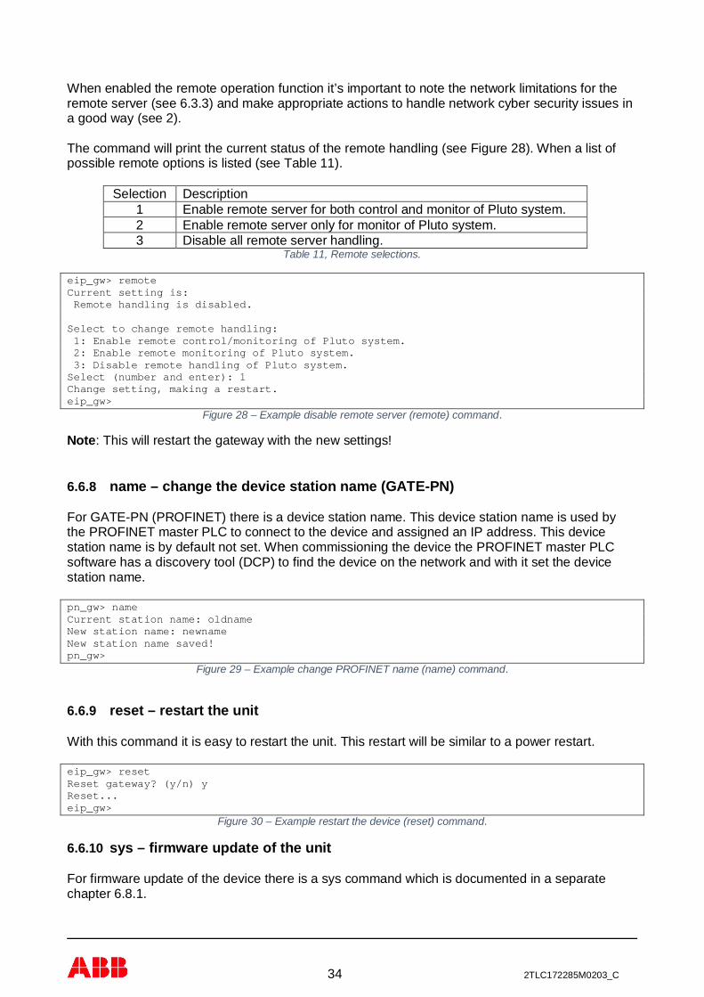
The command will print the current status of the remote handling (see Figure 28). When a list ofpossible remote options is listed (see Table 11).
Selection Description1 Enable remote server for both control and monitor of Pluto system.2 Enable remote server only for monitor of Pluto system.3 Disable all remote server handling.
Table 11, Remote selections.
eip_gw> remoteCurrent setting is: Remote handling is disabled.
Select to change remote handling: 1: Enable remote control/monitoring of Pluto system. 2: Enable remote monitoring of Pluto system. 3: Disable remote handling of Pluto system.Select (number and enter): 1Change setting, making a restart.eip_gw>
Figure 28 – Example disable remote server (remote) command.
Note: This will restart the gateway with the new settings!
6.6.8 name – change the device station name (GATE-PN)
For GATE-PN (PROFINET) there is a device station name. This device station name is used bythe PROFINET master PLC to connect to the device and assigned an IP address. This devicestation name is by default not set. When commissioning the device the PROFINET master PLCsoftware has a discovery tool (DCP) to find the device on the network and with it set the devicestation name.
pn_gw> nameCurrent station name: oldnameNew station name: newnameNew station name saved!pn_gw>
Figure 29 – Example change PROFINET name (name) command.
6.6.9 reset – restart the unit
With this command it is easy to restart the unit. This restart will be similar to a power restart.
eip_gw> resetReset gateway? (y/n) yReset...eip_gw>
Figure 30 – Example restart the device (reset) command.
6.6.10 sys – firmware update of the unit
For firmware update of the device there is a sys command which is documented in a separatechapter 6.8.1.

35 2TLC172285M0203_C
6.6.11 def – restore factory settings
This command restore the device to the factory settings,
- IP address assignment.- Configuration of “Data to Pluto”.- Clear configuration of additional data.- Set default server enable/disable settings.- Clear device station name (GATE-PN).- Read gateway node number from the current DIP switch setting.
Note: This will restart the gateway with the new settings!
eip_gw> defRestore the device to the factory settings? (y/n) yMaking a restart.eip_gw>
Figure 31 – Example restore factory settings (def) command.
6.6.12 dout – disconnect remote clients
With the command “dout” it is possible to disconnect any connected clients to the remote server.This can only be executed via the PC port and NOT via the remote terminal.
6.6.13 test – test command
This command is used during ABB production test and is used together with a specific test system.This command cannot be used to test the device without the test system. The command is onlypresented in the help listing and in this document so it’s not hidden. If this command is started thedevice need to be restarted via power off/on sequence to be operational.
6.7 Silent commands
For remote monitor handling via Pluto Manager the terminal also handles silent commands. Thesecommands start with a “%” character and are not echoed back to the operator. As thesecommands are intended to be used only by Pluto Manager they are not documented within thismanual.
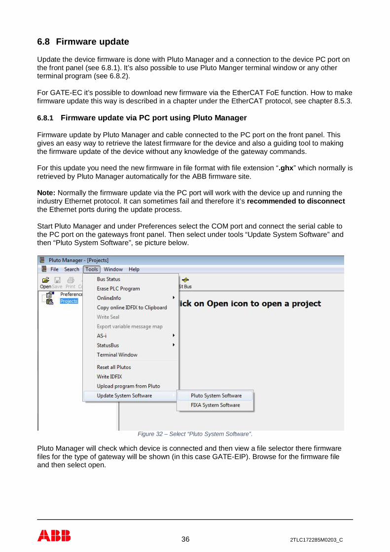
36 2TLC172285M0203_C
6.8 Firmware update
Update the device firmware is done with Pluto Manager and a connection to the device PC port onthe front panel (see 6.8.1). It’s also possible to use Pluto Manger terminal window or any otherterminal program (see 6.8.2).
For GATE-EC it’s possible to download new firmware via the EtherCAT FoE function. How to makefirmware update this way is described in a chapter under the EtherCAT protocol, see chapter 8.5.3.
6.8.1 Firmware update via PC port using Pluto Manager
Firmware update by Pluto Manager and cable connected to the PC port on the front panel. Thisgives an easy way to retrieve the latest firmware for the device and also a guiding tool to makingthe firmware update of the device without any knowledge of the gateway commands.
For this update you need the new firmware in file format with file extension “.ghx” which normally isretrieved by Pluto Manager automatically for the ABB firmware site.
Note: Normally the firmware update via the PC port will work with the device up and running theindustry Ethernet protocol. It can sometimes fail and therefore it’s recommended to disconnectthe Ethernet ports during the update process.
Start Pluto Manager and under Preferences select the COM port and connect the serial cable tothe PC port on the gateways front panel. Then select under tools “Update System Software” andthen “Pluto System Software”, se picture below.
Figure 32 – Select “Pluto System Software”.
Pluto Manager will check which device is connected and then view a file selector there firmwarefiles for the type of gateway will be shown (in this case GATE-EIP). Browse for the firmware fileand then select open.

37 2TLC172285M0203_C
Figure 33 – Select update firmware file.
When firmware file have been selected the file will be sent to the device.
Figure 34 – Selected firmware file sent to the device.
After the firmware file have been sent will be stored in the devices FLASH memory:

38 2TLC172285M0203_C
Figure 35 – Downloaded firmware file is saved on the device.
Last the device will make a restarts to activate the new firmware:
Figure 36 – Firmware file downloaded and device is restarting.
During the restart the gateway will make some checking of the downloaded file and if the file iscorrect it will start the execution of the new firmware.
The complete download and installation will take about 5 minutes.
6.8.2 Firmware update via PC port
The firmware of the device can be updated vid the terminal PC port interface on the front panel byusing the “sys” command and upload the new firmware in file format with file extension “.ghx”.
Note: Normally the firmware update via the PC port will work with the device up and running theindustry Ethernet protocol. It can sometimes fail and therefore it’s recommended to disconnectthe Ethernet ports during the update process.
To make the firmware update enter the command “sys” and press enter! The prompt will tell youto send the firmware file. In Pluto Manager terminal window you select the “Send File” button and

39 2TLC172285M0203_C
select the correct firmware file which will have a file extension named “.ghx”. When selected the filetransfer is started and it will take about 4 to 5 minutes to complete the firmware update.
eip_gw> sysSend file...Saving file...Firmware saved, restarting.eip_gw>
Figure 37 – Example firmware update using terminal (sys) command.
There is no information if the check of the downloaded file fails, the only way to verify firmwareversion is via the version command which is also printed on the terminal at power up.
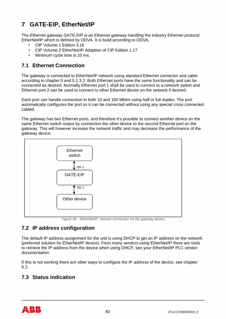
40 2TLC172285M0203_C
7 GATE-EIP, EtherNet/IPThe Ethernet gateway GATE-EIP is an Ethernet gateway handling the industry Ethernet protocolEtherNet/IP which is defined by ODVA. It is build according to ODVA,
· CIP Volume 1 Edition 3.16· CIP Volume 2 EtherNet/IP Adaption of CIP Edition 1.17· Minimum cycle time is 10 ms.
7.1 Ethernet Connection
The gateway is connected to EtherNet/IP network using standard Ethernet connector and cableaccording to chapter 0 and 5.1.3.2. Both Ethernet ports have the same functionality and can beconnected as desired. Normally Ethernet port 1 shall be used to connect to a network switch andEthernet port 2 can be used to connect to other Ethernet device on the network if desired.
Each port can handle connection in both 10 and 100 Mbit/s using half or full duplex. The portautomatically configures the port so it can be connected without using any special cross connectedcabled.
The gateway has two Ethernet ports, and therefore it’s possible to connect another device on thesame Ethernet switch output by connection the other device to the second Ethernet port on thegateway. This will however increase the network traffic and may decrease the performance of thegateway device.
Figure 38 – EtherNet/IP, network connection via the gateway device.
7.2 IP address configuration
The default IP address assignment for the unit is using DHCP to get an IP address on the network(preferred solution for EtherNet/IP device). From many vendors using EtherNet/IP there are toolsto retrieve the IP address from the device when using DHCP, see your EtherNet/IP PLC vendordocumentation.
If this is not working there are other ways to configure the IP address of the device, see chapter6.2.
7.3 Status indication
Ethernetswitch
Other device
Eth 1
Eth 2
GATE-EIP

41 2TLC172285M0203_C
On the gateway with EtherNet/IP there are two dual color LEDs for EtherNet/IP status indications.They are named Module Status (Mod status) and Network Status (Net status). The tables belowexplain the indicators status information.7.3.1 Module Status
LED EtherNet/IP Remark
OFF Unit off
GREENflashing Standby
GREENsteady Operational
REDflashing Minor fault
REDsteady Major fault
GREEN/REDflashing Start-up/Test
Table 12, EtherNet/IP, module status indication behavior.
7.3.2 Network Status
LED EtherNet/IP Remark
OFF Unit off If module status flashing green then the unitis missing IP address.
GREENflashing No connection
GREENsteady Connected
REDflashing Connection timeout
REDsteady Duplicate IP
GREEN/REDflashing Start-up/Test
Table 13, EtherNet/IP, network status indication behavior.
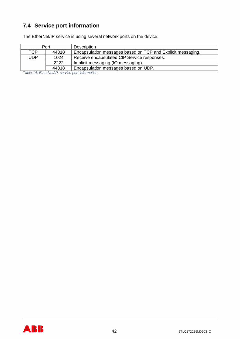
42 2TLC172285M0203_C
7.4 Service port information
The EtherNet/IP service is using several network ports on the device.
Port DescriptionTCP 44818 Encapsulation messages based on TCP and Explicit messaging.UDP 1024 Receive encapsulated CIP Service responses.
2222 Implicit messaging (IO messaging).44818 Encapsulation messages based on UDP.
Table 14, EtherNet/IP, service port information.

43 2TLC172285M0203_C
7.5 Rockwell integration
The EtherNet/IP protocol in the gateway has been implemented according to EtherNet/IP objectdescription in appendix chapter 15.
Example of configuration of an Allen-Bradley Rockwell system under I/O configuration andEthernet add new module for communication of type Generic Ethernet Module,
Figure 39 – EtherNet/IP, add gateway as “Generic Ethernet Module”.
Important settings are:- Name of the Ethernet unit which will give names to the controller tags as,
PLUTO_GATEWAY_1:C control dataPLUTO_GATEWAY_1:I input dataPLUTO_GATEWAY_1:O output data
- IP address of the gateway (see chapter 6.2).- Communication data size format (Comm Format, preferred format is “Data – INT”).- Input assembly instance number and size.- Output assembly instance number and size.- Configuration assembly instance number and size.- Requested Packet Interval (RPI).- Set configuration data.
Input assembly setting
If only input data is used the size can be any of the three showed in the table. If output data is usedor will maybe be used in future the size of INT shall be used.
Input data Instance number Instance sizeData - SINT Data – INT Data – DINT
Status Only 100 4 2 1Data Only 101 256 128 64Status and Data 102 260 130 65Table 15, EtherNet/IP, selecting input data assembly.
Data structure for each instance is like the table below. For detailed information about each partsee chapter 12.1 (status), 12.2 (Data from Pluto) and 12.3 (Additional Data from Pluto). The table

44 2TLC172285M0203_C
below indicates on which byte/word the data is located in depending on data type and usedassembly number (no mapping for DINT data have been shown in this table).
Data Data - SINT (byte) Data - INT (word)100 101 102 100 101 102
Status 0 – 3 - 0 – 3 0 – 1 - 0 – 1Data Pluto 0 - 0 – 3 4 – 7 - 0 – 1 2 – 3Data Pluto 1 - 4 – 7 8 – 11 - 2 – 3 4 – 5Data Pluto 2 - 8 – 11 12 – 15 - 4 – 5 6 – 7Data Pluto 3 - 12 – 15 16 – 19 - 6 – 7 8 – 9Data Pluto 4 - 16 – 19 20 – 23 - 8 – 9 10 – 11Data Pluto 5 - 20 – 23 24 – 27 - 10 – 11 12 – 13Data Pluto 6 - 24 – 27 28 – 31 - 12 – 13 14 – 15Data Pluto 7 - 28 – 31 32 – 35 - 14 – 15 16 – 17Data Pluto 8 - 32 – 35 36 – 39 - 16 – 17 18 – 19Data Pluto 9 - 36 – 39 40 – 43 - 18 – 19 20 – 21Data Pluto 10 - 40 – 43 44 – 47 - 20 – 21 22 – 23Data Pluto 11 - 44 – 47 48 – 51 - 22 – 23 24 – 25Data Pluto 12 - 48 – 51 52 – 55 - 24 – 25 26 – 27Data Pluto 13 - 52 – 55 56 – 59 - 26 – 27 28 – 29Data Pluto 14 - 56 – 59 60 – 63 - 28 – 29 30 – 31Data Pluto 15 - 60 – 63 64 – 67 - 30 – 31 32 – 33Data Pluto 16 - 64 – 67 68 – 71 - 32 – 33 34 – 35Data Pluto 17 - 68 – 71 72 – 75 - 34 – 35 36 – 37Data Pluto 18 - 72 – 75 76 – 79 - 36 – 37 38 – 39Data Pluto 19 - 76 – 79 80 – 83 - 38 – 39 40 – 41Data Pluto 20 - 80 – 83 84 – 87 - 40 – 41 42 – 43Data Pluto 21 - 84 – 87 88 – 91 - 42 – 43 44 – 45Data Pluto 22 - 88 – 91 92 – 95 - 44 – 45 46 – 47Data Pluto 23 - 92 – 95 96 – 99 - 46 – 47 48 – 49Data Pluto 24 - 96 – 99 100–103 - 48 – 49 50 – 51Data Pluto 25 - 100–103 104–107 - 50 – 51 52 – 53Data Pluto 26 - 104–107 108–111 - 52 – 53 54 – 55Data Pluto 27 - 108–111 112–115 - 54 – 55 56 – 57Data Pluto 28 - 112–115 116–119 - 56 – 57 58 – 59Data Pluto 29 - 116–119 120–123 - 58 – 59 60 – 61Data Pluto 30 - 120–123 124–127 - 60 – 61 62 – 63Data Pluto 31 - 124–127 128–131 - 62 – 63 64 – 65Additional Data 00 - 128–131 132–135 - 64 – 65 66 – 67Additional Data 01 - 132–135 136–139 - 66 – 67 68 – 69Additional Data 02 - 136–139 140–143 - 68 – 69 70 – 71Additional Data 03 - 140–143 144–147 - 70 – 71 72 – 73Additional Data 04 - 144–147 148–151 - 72 – 73 74 – 75Additional Data 05 - 148–151 152–155 - 74 – 75 76 – 77Additional Data 06 - 152–155 156–159 - 76 – 77 78 – 79Additional Data 07 - 156–159 160–163 - 78 – 79 80 – 81Additional Data 08 - 160–163 164–167 - 80 – 81 82 – 83Additional Data 09 - 164–167 168–171 - 82 – 83 84 – 85Additional Data 10 - 168–171 172–175 - 84 – 85 86 – 86Additional Data 11 - 172–175 176–179 - 86 – 86 88 – 89Additional Data 12 - 176–179 180–183 - 88 – 89 90 – 91Additional Data 13 - 180–183 184–187 - 90 – 91 92 – 93Additional Data 14 - 184–187 188–191 - 92 – 93 94 – 95Additional Data 15 - 188–191 192–195 - 94 – 95 96 – 97Additional Data 16 - 192–195 196–199 - 96 – 97 98 – 99
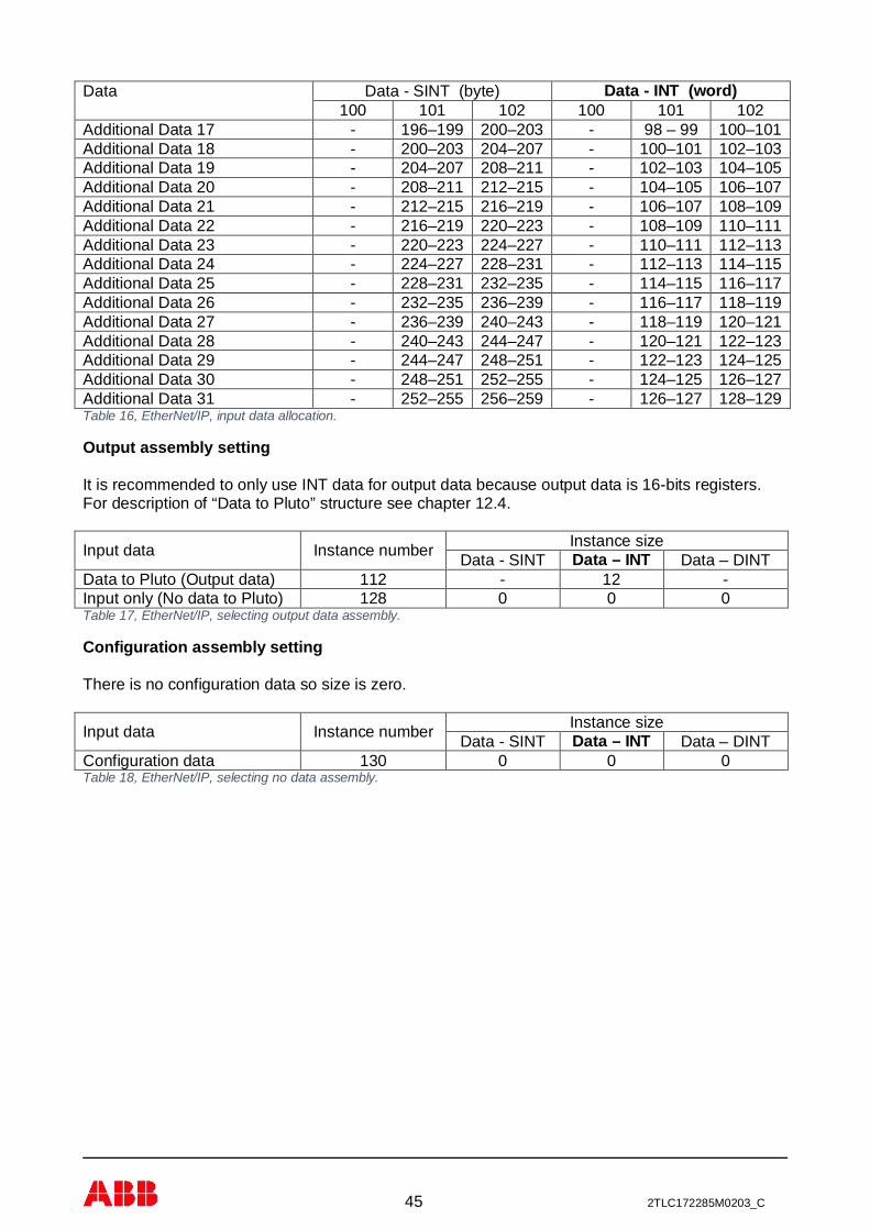
45 2TLC172285M0203_C
Data Data - SINT (byte) Data - INT (word)100 101 102 100 101 102
Additional Data 17 - 196–199 200–203 - 98 – 99 100–101Additional Data 18 - 200–203 204–207 - 100–101 102–103Additional Data 19 - 204–207 208–211 - 102–103 104–105Additional Data 20 - 208–211 212–215 - 104–105 106–107Additional Data 21 - 212–215 216–219 - 106–107 108–109Additional Data 22 - 216–219 220–223 - 108–109 110–111Additional Data 23 - 220–223 224–227 - 110–111 112–113Additional Data 24 - 224–227 228–231 - 112–113 114–115Additional Data 25 - 228–231 232–235 - 114–115 116–117Additional Data 26 - 232–235 236–239 - 116–117 118–119Additional Data 27 - 236–239 240–243 - 118–119 120–121Additional Data 28 - 240–243 244–247 - 120–121 122–123Additional Data 29 - 244–247 248–251 - 122–123 124–125Additional Data 30 - 248–251 252–255 - 124–125 126–127Additional Data 31 - 252–255 256–259 - 126–127 128–129Table 16, EtherNet/IP, input data allocation.
Output assembly setting
It is recommended to only use INT data for output data because output data is 16-bits registers.For description of “Data to Pluto” structure see chapter 12.4.
Input data Instance number Instance sizeData - SINT Data – INT Data – DINT
Data to Pluto (Output data) 112 - 12 -Input only (No data to Pluto) 128 0 0 0Table 17, EtherNet/IP, selecting output data assembly.
Configuration assembly setting
There is no configuration data so size is zero.
Input data Instance number Instance sizeData - SINT Data – INT Data – DINT
Configuration data 130 0 0 0Table 18, EtherNet/IP, selecting no data assembly.

46 2TLC172285M0203_C
Requested Packet Interval (RPI)
Under the connection tab the Requested Packet Interval (RPI) shall be set to desired value, but itshall not be less than 10 ms.
Figure 40 – EtherNet/IP, select RPI (not less than 10 ms).
Set configuration data
After the PLC has established connection and/or done a reconnection to the gateway, the PLCcan/shall send configuration messages to the gateway if needed. It is possible to sendconfiguration data by using message blocks. Configuration settings are related to “Data to Pluto”information to enable packet area (attribute 0x10) and timeout (attribute 0x11), see example belowand chapter 12.4.
Figure 41 – EtherNet/IP, add configuration command.
Figure 42 – EtherNet/IP, example set enable bits by a write to attribute 0x10.

47 2TLC172285M0203_C
Figure 43 – EtherNet/IP, example set enable bits by a write to attribute 0x11.
There is also configuration get/set for additional data via the same feature but using other attributenumbers in the message. For more information see appendix and also chapter 12.3.
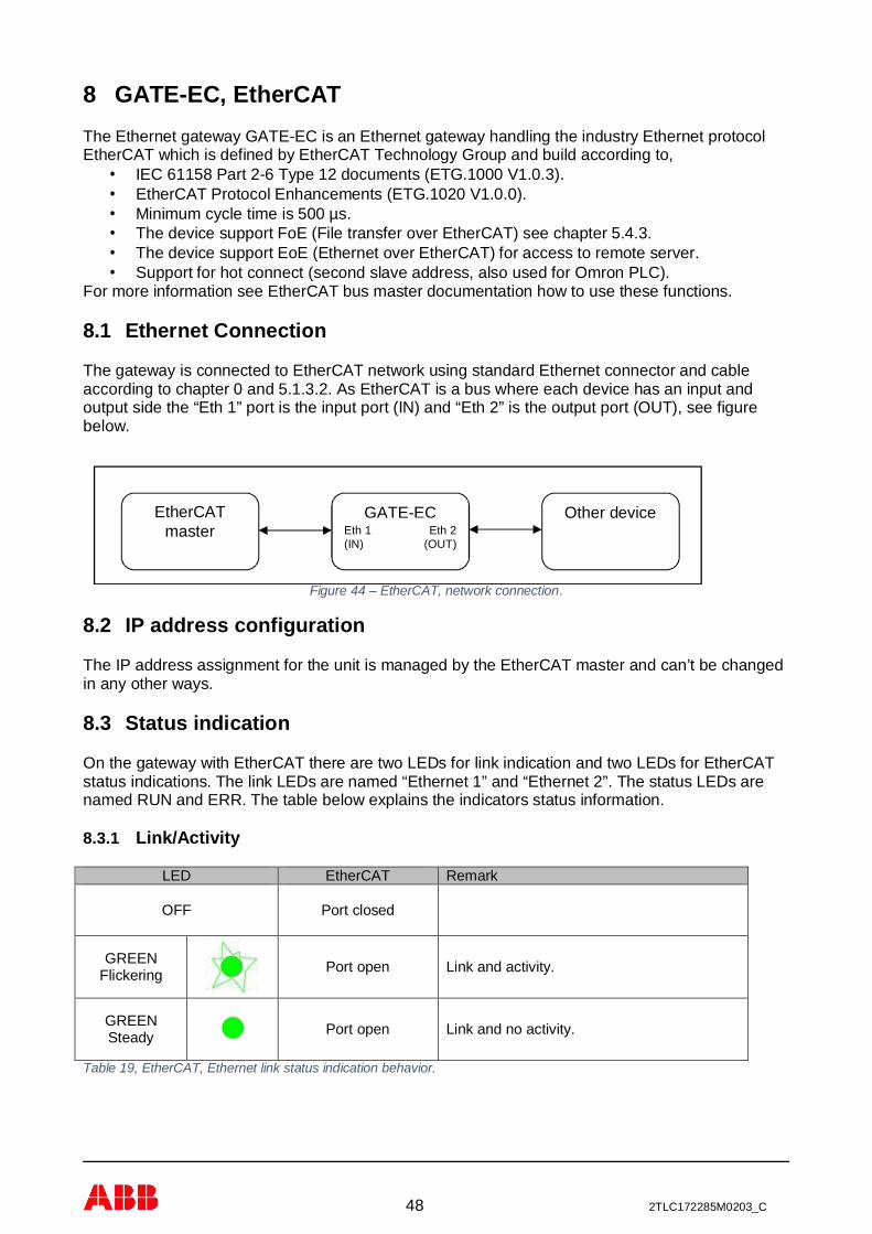
48 2TLC172285M0203_C
8 GATE-EC, EtherCATThe Ethernet gateway GATE-EC is an Ethernet gateway handling the industry Ethernet protocolEtherCAT which is defined by EtherCAT Technology Group and build according to,
· IEC 61158 Part 2-6 Type 12 documents (ETG.1000 V1.0.3).· EtherCAT Protocol Enhancements (ETG.1020 V1.0.0).· Minimum cycle time is 500 µs.· The device support FoE (File transfer over EtherCAT) see chapter 5.4.3.· The device support EoE (Ethernet over EtherCAT) for access to remote server.· Support for hot connect (second slave address, also used for Omron PLC).
For more information see EtherCAT bus master documentation how to use these functions.
8.1 Ethernet Connection
The gateway is connected to EtherCAT network using standard Ethernet connector and cableaccording to chapter 0 and 5.1.3.2. As EtherCAT is a bus where each device has an input andoutput side the “Eth 1” port is the input port (IN) and “Eth 2” is the output port (OUT), see figurebelow.
Figure 44 – EtherCAT, network connection.
8.2 IP address configuration
The IP address assignment for the unit is managed by the EtherCAT master and can’t be changedin any other ways.
8.3 Status indication
On the gateway with EtherCAT there are two LEDs for link indication and two LEDs for EtherCATstatus indications. The link LEDs are named “Ethernet 1” and “Ethernet 2”. The status LEDs arenamed RUN and ERR. The table below explains the indicators status information.
8.3.1 Link/Activity
LED EtherCAT Remark
OFF Port closed
GREENFlickering Port open Link and activity.
GREENSteady Port open Link and no activity.
Table 19, EtherCAT, Ethernet link status indication behavior.
EtherCATmaster
Other deviceGATE-ECEth 1(IN)
Eth 2(OUT)

49 2TLC172285M0203_C
8.3.2 RUN Status
LED EtherCAT Remark
OFF Init
GREENBlinking Pre-Operational
GREENSingle Flash Safe-Operational
GREENFlickering
Initialization orBootstrap
GREENSteady Operational
Table 20, EtherCAT, RUN status indication behavior.
8.3.3 Error Status
LED EtherCAT Remark
OFF No error
REDBlinking Invalid Configuration
REDSingle Flash
Unsolicited StateChange
REDDouble Flash
Application WatchdogTimeout
REDFlickering Booting Error
REDSteady
PDI WatchdogTimeout
Table 21, EtherCAT, ERROR status indication behavior.

50 2TLC172285M0203_C
8.3.4 LED handling
Indicator states DefinitionOn The indicator shall be constantly on.Off The indicator shall be constantly off.Flickering The indicator shall turn on and off iso-phase with a frequency of 10 Hz: on
for 50 ms and off for 50 ms.Blinking The indicator shall turn on and off iso-phase with a frequency of 2.5 Hz: on
for 200 ms followed by off for 200 ms.Single Flash The indicator shall show one short flash (200 ms) followed by a long off
phase (1000 ms).Double Flash The indicator shall show a sequence of two short flashes (200 ms),
separated by an off phase (200 ms), and followed by a long off phase(1000 ms).
Table 22, EtherCAT, define of different type of LED indication behavior.
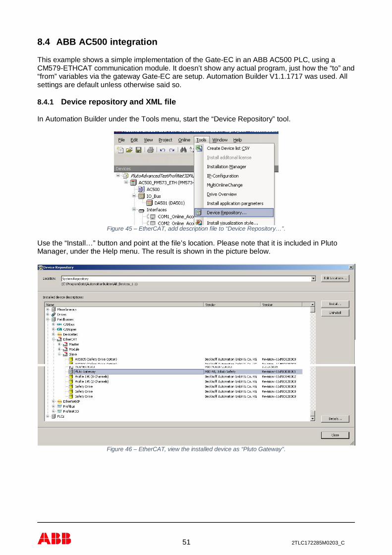
51 2TLC172285M0203_C
8.4 ABB AC500 integration
This example shows a simple implementation of the Gate-EC in an ABB AC500 PLC, using aCM579-ETHCAT communication module. It doesn’t show any actual program, just how the “to” and“from” variables via the gateway Gate-EC are setup. Automation Builder V1.1.1717 was used. Allsettings are default unless otherwise said so.
8.4.1 Device repository and XML file
In Automation Builder under the Tools menu, start the “Device Repository” tool.
Figure 45 – EtherCAT, add description file to “Device Repository…”.
Use the “Install…” button and point at the file’s location. Please note that it is included in PlutoManager, under the Help menu. The result is shown in the picture below.
Figure 46 – EtherCAT, view the installed device as “Pluto Gateway”.
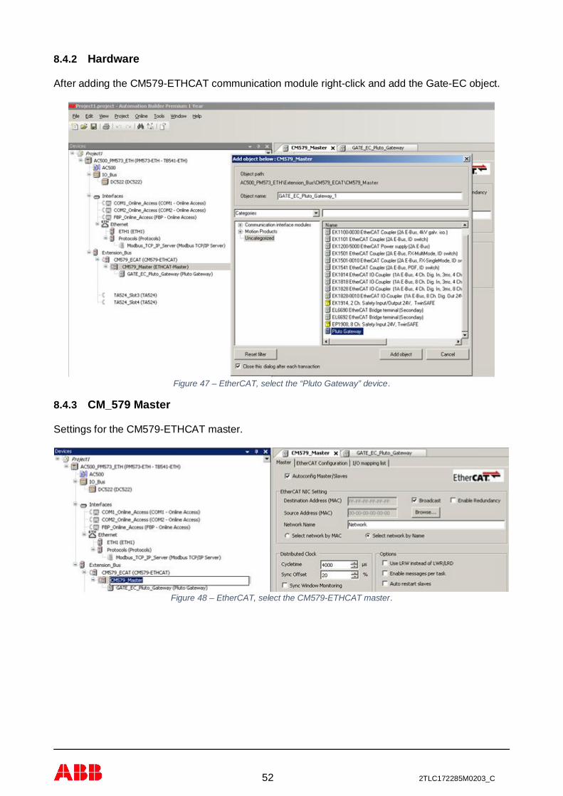
52 2TLC172285M0203_C
8.4.2 Hardware
After adding the CM579-ETHCAT communication module right-click and add the Gate-EC object.
Figure 47 – EtherCAT, select the “Pluto Gateway” device.
8.4.3 CM_579 Master
Settings for the CM579-ETHCAT master.
Figure 48 – EtherCAT, select the CM579-ETHCAT master.

53 2TLC172285M0203_C
8.4.4 Gate_EC_Pluto_Gateway
The picture below shows the default settings used for the gateway.
Figure 49 – EtherCAT, “Pluto Gateway” default setting.
In this example everything has been included but it doesn’t have to be so.
Figure 50 – EtherCAT, example of including all input and outputs.

54 2TLC172285M0203_C
8.4.5 Startup parameters
It is advised to include all “Additional Data” areas so they are initialized to zero at startup.
Figure 51 – EtherCAT, include configuration of all additional data.
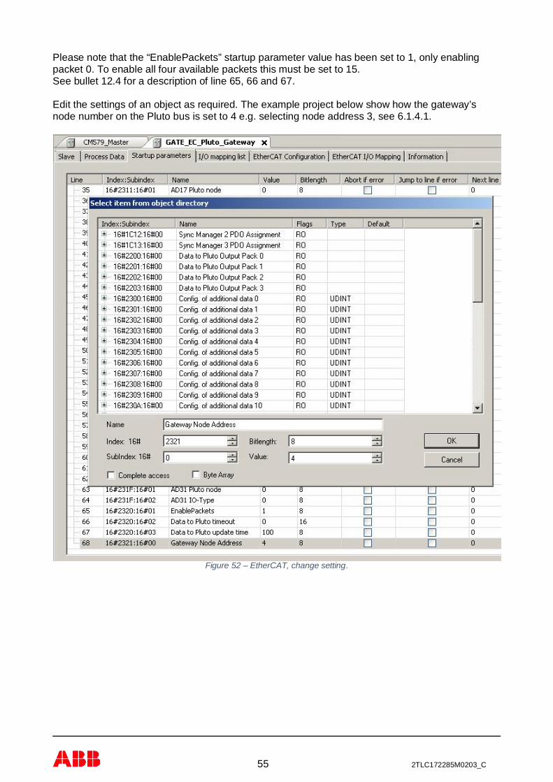
55 2TLC172285M0203_C
Please note that the “EnablePackets” startup parameter value has been set to 1, only enablingpacket 0. To enable all four available packets this must be set to 15.See bullet 12.4 for a description of line 65, 66 and 67.
Edit the settings of an object as required. The example project below show how the gateway’snode number on the Pluto bus is set to 4 e.g. selecting node address 3, see 6.1.4.1.
Figure 52 – EtherCAT, change setting.

56 2TLC172285M0203_C
8.4.6 I/O mapping list
Enter the names of the variables that will be used in the CoDeSys environment.
Figure 53 – EtherCAT, add names for the variables.
Result as shown in the CoDeSys environment programming tool.
Figure 54 – EtherCAT, variable names in CoDeSys.

57 2TLC172285M0203_C
8.5 Beckhoff TwinCAT integration
This chapter will describe how to use the gateway GATE-EC with Beckhoff TwinCAT system.
8.5.1 Add device description file
The description file for EtherCAT is called ESI XML files. For the gateway GATE-EC this file isnamed “ABB_JokabSafety_GATE-EC.xml”. Installation is easily done by copying the file into thecorrect TwinCAT directory.
For TwinCAT 2 copy the file into “TwinCAT\Io\EtherCAT” directory.
After the installation of the file you need to restart system manager so it will reread theconfiguration directory for new information.
8.5.2 Scan system for the device
The unit will be easily installed into a system by scanning the system for boxes. During this scan itwill detect the gateway GATE-EC and generate a box for it where all settings and data then will beavailable, see picture below.
Figure 55 – EtherCAT, result of scanning the system with GATE-EC.
8.5.3 Firmware update
With system supporting FoE (File access over EtherCAT) it’s possible to update the devicefirmware in the gateway GATE-EC. In a Beckhoff TwinCAT system the file download button can befound in the “Online” tab of the device,
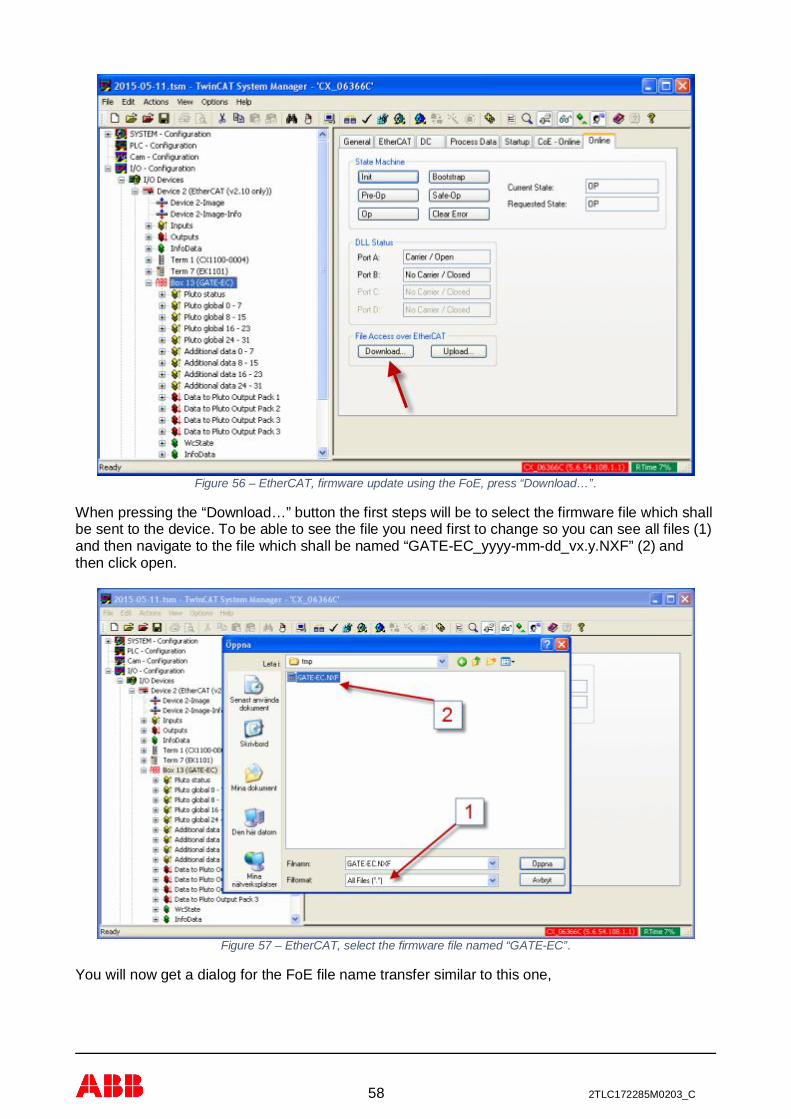
58 2TLC172285M0203_C
Figure 56 – EtherCAT, firmware update using the FoE, press “Download…”.
When pressing the “Download…” button the first steps will be to select the firmware file which shallbe sent to the device. To be able to see the file you need first to change so you can see all files (1)and then navigate to the file which shall be named “GATE-EC_yyyy-mm-dd_vx.y.NXF” (2) andthen click open.
Figure 57 – EtherCAT, select the firmware file named “GATE-EC”.
You will now get a dialog for the FoE file name transfer similar to this one,
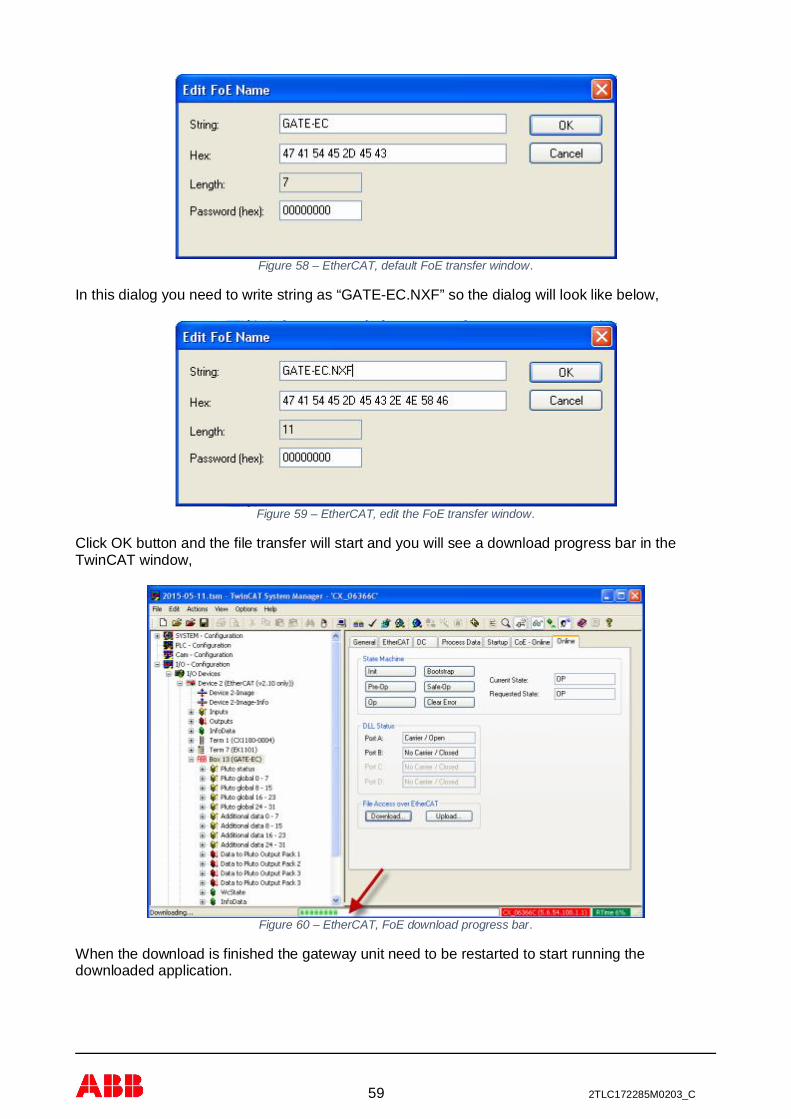
59 2TLC172285M0203_C
Figure 58 – EtherCAT, default FoE transfer window.
In this dialog you need to write string as “GATE-EC.NXF” so the dialog will look like below,
Figure 59 – EtherCAT, edit the FoE transfer window.
Click OK button and the file transfer will start and you will see a download progress bar in theTwinCAT window,
Figure 60 – EtherCAT, FoE download progress bar.
When the download is finished the gateway unit need to be restarted to start running thedownloaded application.
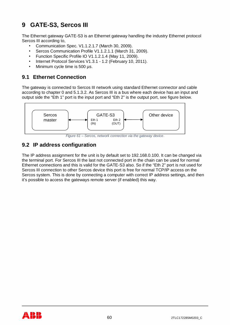
60 2TLC172285M0203_C
9 GATE-S3, Sercos IIIThe Ethernet gateway GATE-S3 is an Ethernet gateway handling the industry Ethernet protocolSercos III according to,
· Communication Spec. V1.1.2.1.7 (March 30, 2009).· Sercos Communication Profile V1.1.2.1.1 (March 31, 2009).· Function Specific Profile IO V1.1.2.1.4 (May 11, 2009).· Internet Protocol Services V1.3.1 - 1.2 (February 10, 2011).· Minimum cycle time is 500 µs.
9.1 Ethernet Connection
The gateway is connected to Sercos III network using standard Ethernet connector and cableaccording to chapter 0 and 5.1.3.2. As Sercos III is a bus where each device has an input andoutput side the “Eth 1” port is the input port and “Eth 2” is the output port, see figure below.
Figure 61 – Sercos, network connection via the gateway device.
9.2 IP address configuration
The IP address assignment for the unit is by default set to 192.168.0.100. It can be changed viathe terminal port. For Sercos III the last not connected port in the chain can be used for normalEthernet connections and this is valid for the GATE-S3 also. So if the “Eth 2” port is not used forSercos III connection to other Sercos device this port is free for normal TCP/IP access on theSercos system. This is done by connecting a computer with correct IP address settings, and thenit’s possible to access the gateways remote server (if enabled) this way.
Sercosmaster
Other deviceGATE-S3Eth 1(IN)
Eth 2(OUT)

61 2TLC172285M0203_C
9.3 Status indication
On the gateway with Sercos III there are one dual colors LED for Sercos III status indication,named S3. Currently this is not a true dual color LED as stated in the Sercos specification but ithas the same behavior. The tables below explain the indicators status information, when both thegreen and red light the color shall be orange.
Pattern Color Description Priority Comment1 NRT-Mode 0 No SERCOS communication
2 CP0 0 Communication phase 0 is active
3 CP1 0 Communication phase 1 is active
4 CP2 0 Communication phase 2 is active
5 CP3 0 Communication phase 3 is active
6 CP4 0 Communication phase 4 is active
7 HP0 1 Device is in hot-plug phase 0
8 HP1 1 Device is in hot-plug phase 1
9 HP2 1 Device is in hot-plug phase 2
10 Fast forward ⇒Loopback
2 RT-state has changed from fast-forward toloopback
11 Application error 3 See GDP & FSP Status codes class error
12 MST losses ≥ (S-0-1003/2)
4 As long as the communication warning (S-DEV.Bit15) in the Device Status ispresent, at least 2 sec.
13 Communication error 5 See SCP Status codes class error
14 Identification 6 Invoked by (C-DEV.Bit 15 in the DeviceControl) or SIP Identification request
15 Watchdog error 7 Application is not running
3 seconds, each flash 250 ms.Table 23, Sercos, status indication behavior.
9.4 Service port information
The Sercos III service is using several network ports on the device.
Port DescriptionUDP 35021 Encapsulation messages based on UDP.
Table 24, Sercos, service port information.

62 2TLC172285M0203_C
9.5 Bosch-Rexroth IndraWorks integration
This chapter will highlight some aspects on integrating gateway GATE-S3 with a Bosch-RexrothIndraWorks system.
9.5.1 Add device description file
Select in IndraWorks menu “Tools” and “Device Database…” which will bring up this window,
Figure 62 – Sercos, add the description file.
Press the ”Add Devices…” button and select the description file for the gateway GATE-S3 devicewhich is named something like
”SDDML#3.0#ABB_AB_JOKAB_SAFETY#ABB_GATE-S3#2015-03-25.xml”.
If a correct installation you can see the device in the “Device database” under the directory“Fieldbusses” – “Sercos3” – “Slave” – “ABB GATE-S3”, see picture below.
Figure 63 – Sercos, view the installed description file as “ABB GATE-S3”.

63 2TLC172285M0203_C
9.5.2 Scan system for the device
The unit will be easily installed into a system by scanning the Sercos bus by right click on theSercos bus in the project and select “Scan Bus Configuration”. During this scan it will detect thegateway GATE-S3 and add it to the project via the “Scan Bus Configuration” windows which willfollow the scan of the bus.
Figure 64 – Sercos, scan the bus with “Scan Bus Configuration”.
After adding the device the project explorer will view the gateway in a way similar to the examplebelow,
Figure 65 – Sercos, example of the project after adding the gateway.

64 2TLC172285M0203_C
9.5.3 Gateway configuration
By clicking on the two gateway modules in the project explorer it’s now possible to configure thegateway device as needed. For example the startup configuration can be updated via “UserParameter” tab.
Figure 66 – Sercos, change gateway configuration.

65 2TLC172285M0203_C
10 GATE-PN, PROFINETThe Ethernet gateway GATE-PN is an Ethernet gateway handling the industry Ethernet protocolPROFINET which is defined by PI Organization. It is build according to,
· Specification for PROFINET, Version 2.31.· IRT Top (“Red phase”) will be supported.· Minimum cycle time 2ms for RTC1 and 1ms for RTC3.
Note: LimitationMinimum cycle time of 1 and 2 ms are today only possible when the Pluto system has maximum 8Pluto units. For cycle time below 10 ms the limits are maximum 16 Pluto units. From 10 ms and up,a full Pluto system can be used.
10.1 Description file
The description file (GSSML) is the description file which shall be imported into the master PLCconfiguration tool.
The description file has two access points,
- GATE-E2 (Compatibility Mode).This access point shall only be used as a backward compatibility access point when makingdirect replacement of GATE-E2 device.
Shall not be used for new system configuration!
- GATE-PN.This is the access point which shall be used in new system configurations.
For more information see PROFINET description appendix at chapter 18.
10.2 Data format
Pluto data in chapter 12 (Pluto global data 12.2, Pluto additional data 12.3 and data to Pluto 12.4)is in little endian format but data received/transmitted via PROFINET will in the master PLC be inbig endian format. The table below show how this effects how data is arranged in the master PLCmemory.
Unsigned32 Unsigned16PLC
memoryWeight Pluto global byte
order see 12.2Additional byteorder see 12.3
PLCmemory
Weight
0 MSB 3 3 0 MSB1 2 2 1 LSB2 1 13 LSB 0 0
Table 25, PROFINET, data format.
10.3 Ethernet Connection
The gateway is connected to PROFINET network using standard Ethernet connector and cableaccording to chapter 0 and 5.1.3.2. Both Ethernet ports have the same functionality and can beconnected as desired. Normally Ethernet port 1 shall be used to connect to a network switch andEthernet port 2 can be used to connect to other Ethernet device on the network if desired.
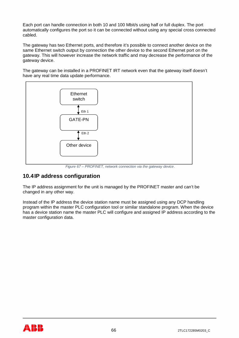
66 2TLC172285M0203_C
Each port can handle connection in both 10 and 100 Mbit/s using half or full duplex. The portautomatically configures the port so it can be connected without using any special cross connectedcabled.
The gateway has two Ethernet ports, and therefore it’s possible to connect another device on thesame Ethernet switch output by connection the other device to the second Ethernet port on thegateway. This will however increase the network traffic and may decrease the performance of thegateway device.
The gateway can be installed in a PROFINET IRT network even that the gateway itself doesn’thave any real time data update performance.
Figure 67 – PROFINET, network connection via the gateway device.
10.4 IP address configuration
The IP address assignment for the unit is managed by the PROFINET master and can’t bechanged in any other way.
Instead of the IP address the device station name must be assigned using any DCP handlingprogram within the master PLC configuration tool or similar standalone program. When the devicehas a device station name the master PLC will configure and assigned IP address according to themaster configuration data.
Ethernetswitch
Other device
Eth 1
Eth 2
GATE-PN
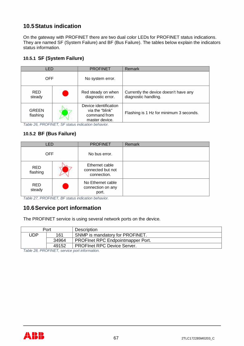
67 2TLC172285M0203_C
10.5 Status indication
On the gateway with PROFINET there are two dual color LEDs for PROFINET status indications.They are named SF (System Failure) and BF (Bus Failure). The tables below explain the indicatorsstatus information.
10.5.1 SF (System Failure)
LED PROFINET Remark
OFF No system error.
REDsteady
Red steady on whendiagnostic error.
Currently the device doesn’t have anydiagnostic handling.
GREENflashing
Device identificationvia the “blink”
command frommaster device.
Flashing is 1 Hz for minimum 3 seconds.
Table 26, PROFINET, SF status indication behavior.
10.5.2 BF (Bus Failure)
LED PROFINET Remark
OFF No bus error.
REDflashing
Ethernet cableconnected but not
connection.
REDsteady
No Ethernet cableconnection on any
port.Table 27, PROFINET, BF status indication behavior.
10.6 Service port information
The PROFINET service is using several network ports on the device.
Port DescriptionUDP 161 SNMP is mandatory for PROFINET.
34964 PROFInet RPC Endpointmapper Port.49152 PROFInet RPC Device Server.
Table 28, PROFINET, service port information.

68 2TLC172285M0203_C
10.7 ABB AC500 implementation
This example shows a simple implementation of the Gate-PN in an ABB AC500 PLC, using aCM579-PNIO communication module. It doesn’t show any actual program, just how the “to” and“from” variables via the gateway Gate-PN are setup. Automation Builder V1.1.1717 was used.
10.7.1 Device repository and XML file
In Automation Builder under the Tools menu, start the “Device Repository” tool.
Figure 68 – PROFINET, add description file to “Device Repository…”.
Use the “Install…” button and point at the file’s location. Please note that it is included in PlutoManager, under the Help menu. The result is shown in the picture below.
Figure 69 – PROFINET, view the installed device as “GATE-PN”.

69 2TLC172285M0203_C
10.7.2 Hardware
After adding the CM579-PNIO communication module right-click and add the Gate-PN object.
10.7.2.1 Adding objects
Add objects by right-clicking. Please note that each object under the Gate-PN has a specific placein the structure. “Node_Status” below must always be in the first location, “Pluto_Nodes_00_07” inthe second, “Pluto_Nodes_08_15 in the third”, and so on.
Figure 70 – PROFINET, adding modules.
The result when all object has been added. Please note that you may need to configure someobjects further.
Figure 71 – PROFINET, example adding all modules.
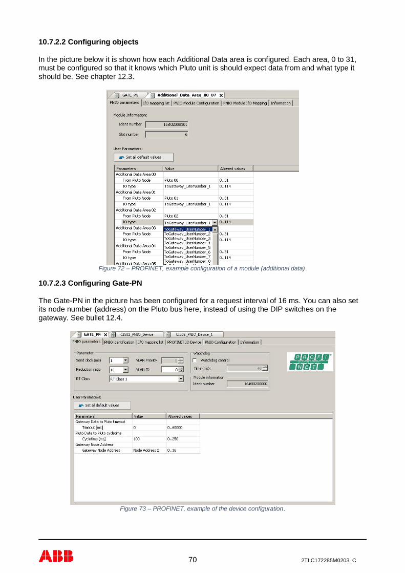
70 2TLC172285M0203_C
10.7.2.2 Configuring objects
In the picture below it is shown how each Additional Data area is configured. Each area, 0 to 31,must be configured so that it knows which Pluto unit is should expect data from and what type itshould be. See chapter 12.3.
Figure 72 – PROFINET, example configuration of a module (additional data).
10.7.2.3 Configuring Gate-PN
The Gate-PN in the picture has been configured for a request interval of 16 ms. You can also setits node number (address) on the Pluto bus here, instead of using the DIP switches on thegateway. See bullet 12.4.
Figure 73 – PROFINET, example of the device configuration.

71 2TLC172285M0203_C
10.7.3 PROFINET name
Either use Pluto Manager, Tools menu, Terminal Window (NAME command), and a programmingcable connected to the gateway, or use the tool under the CM579-PNIO communication module toassign a PROFINET name to the gateway. This will establish communication with the gateway.
Figure 74 – PROFINET, setting device name.

72 2TLC172285M0203_C
10.7.4 Assigning variable names
Use the I/O mapping list to assign variables their names.
Figure 75 – PROFINET, add names (assigning) for the variables.
This is how they will show up in the CoDeSys environment, ready to be used.
Figure 76 – PROFINET, variable names in CoDeSys.
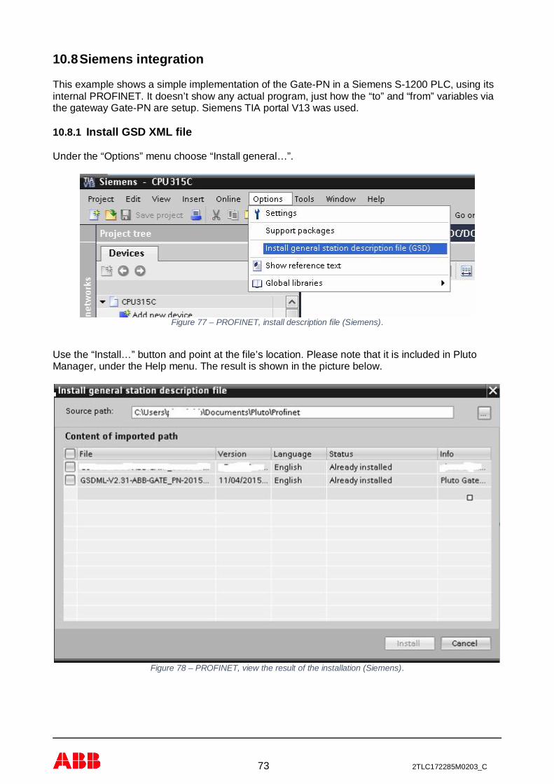
73 2TLC172285M0203_C
10.8 Siemens integration
This example shows a simple implementation of the Gate-PN in a Siemens S-1200 PLC, using itsinternal PROFINET. It doesn’t show any actual program, just how the “to” and “from” variables viathe gateway Gate-PN are setup. Siemens TIA portal V13 was used.
10.8.1 Install GSD XML file
Under the “Options” menu choose “Install general…”.
Figure 77 – PROFINET, install description file (Siemens).
Use the “Install…” button and point at the file’s location. Please note that it is included in PlutoManager, under the Help menu. The result is shown in the picture below.
Figure 78 – PROFINET, view the result of the installation (Siemens).

74 2TLC172285M0203_C
10.8.2 Add the device to the PROFINET network
Use the “Devices & Networks” to add the Gate-PN. Please note that the PLC and gateway must belinked to each other with PROFINET network intended to be used.
Figure 79 – PROFINET, add gateway to network (Siemens).
10.8.2.1 PROFINET name and IP address
Mark the gateway and use Properties to set its IP address. The name is default “gatepn”. This canbe changed either via Pluto Manager, Tools menu, Terminal Window (NAME command), and aprogramming cable connected to the gateway, or use “Online access” and connect to the gatewayif it’s reachable, use “Functions” to assign the name and IP address.
Figure 80 – PROFINET, assign name for the gateway device (Siemens).

75 2TLC172285M0203_C
10.8.2.2 IO Cycle
Set the gateway’s IO cycle, either automatically or manually. Here it’s been set manually to 16 ms.
Figure 81 – PROFINET, setting IO cycle time (Siemens).
10.8.2.3 Module parameters of the Head module
Under the “Module parameters” tab settings concerning the gateways behavior on the Pluto bus issetup. See bullet 12.4.
Figure 82 – PROFINET, example of the device configuration (Siemens).

76 2TLC172285M0203_C
10.8.2.4 Device view
Adding module is done under the “Device view”.
Figure 83 – PROFINET, adding module to the gateway (Siemens).
10.8.2.4.1 Adding modules under the Head module
Drag and drop the modules intended to be used from the “Hardware catalog”. Please note thateach module has its intended fixed placement. “Node Status” first, “Pluto Nodes 00-07” second,and so on. As shown in the picture.
Figure 84 – PROFINET, adding module to the gateway (Siemens).
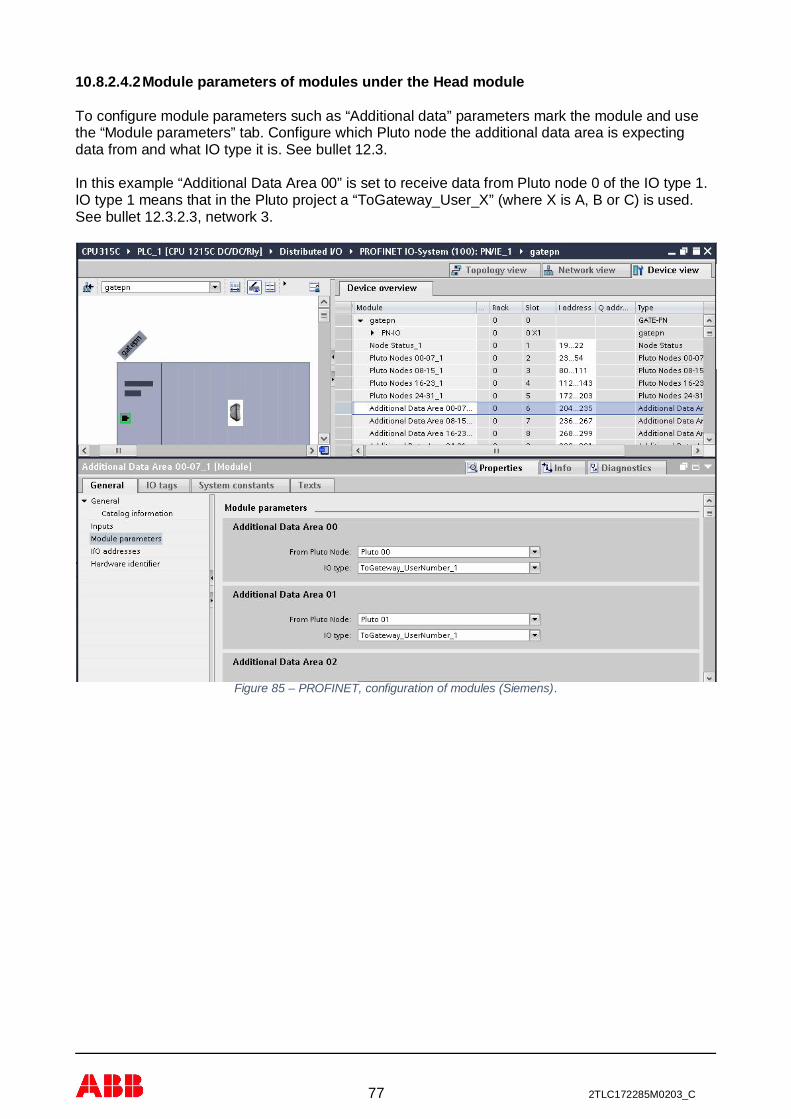
77 2TLC172285M0203_C
10.8.2.4.2 Module parameters of modules under the Head module
To configure module parameters such as “Additional data” parameters mark the module and usethe “Module parameters” tab. Configure which Pluto node the additional data area is expectingdata from and what IO type it is. See bullet 12.3.
In this example “Additional Data Area 00” is set to receive data from Pluto node 0 of the IO type 1.IO type 1 means that in the Pluto project a “ToGateway_User_X” (where X is A, B or C) is used.See bullet 12.3.2.3, network 3.
Figure 85 – PROFINET, configuration of modules (Siemens).

78 2TLC172285M0203_C
10.8.2.4.3 Addressing of in- and out-data
Point the modules to the intended input address or output address. In this example this has beendone automatically.
Figure 86 – PROFINET, setting input and output address (Siemens).
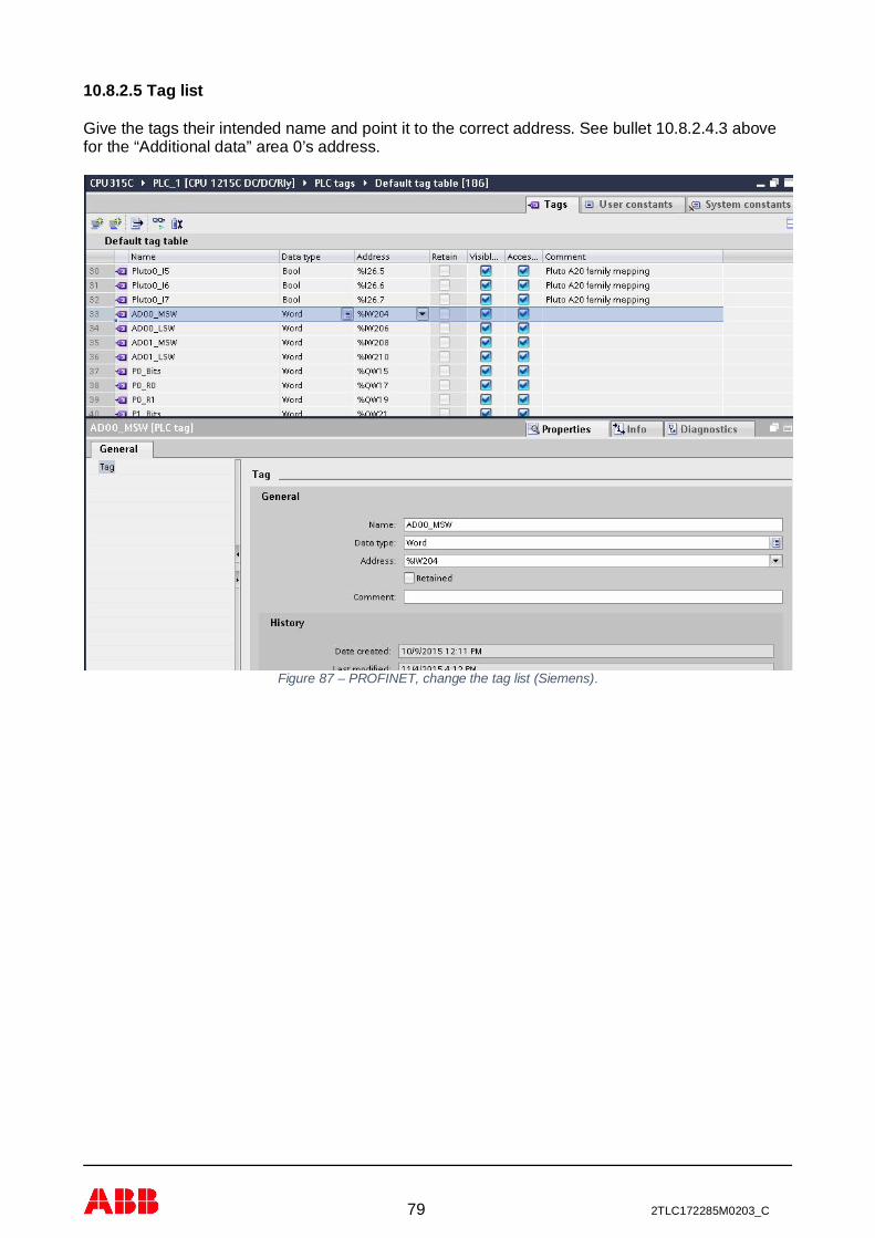
79 2TLC172285M0203_C
10.8.2.5 Tag list
Give the tags their intended name and point it to the correct address. See bullet 10.8.2.4.3 abovefor the “Additional data” area 0’s address.
Figure 87 – PROFINET, change the tag list (Siemens).

80 2TLC172285M0203_C
10.8.2.5.1 Example of Pluto A20 family mapping
See chapter 12, bullet 12.2 for the Global variables mapping and bullet 12.3 for the “AdditionalData” mapping. Plus bullet 10.2 for the data format.
Figure 88 – PROFINET, example of the Pluto A20 tagging (Siemens).

81 2TLC172285M0203_C
11 GATE-MT, Modbus TCPThe Ethernet gateway GATE-MT is an Ethernet gateway handling the industry Modbus TCP whichis defined by Modbus Organization. It is build according to,
· MODBUS Application Protocol Specification, V1.1a, June 4, 2004. · MODBUS Messaging on TCP/IP Implementation Guide, V1.0a, June 4, 2004.· Minimum 500 request per seconds for one steady open connection with about 1 ms
response time.· Maximum of 8 client connections.
11.1 Ethernet Connection
The gateway is connected to Ethernet network using standard Ethernet connector and cableaccording to chapter 0 and 5.1.3.2. Both Ethernet ports have the same functionality and can beconnected as desired. Normally Ethernet port 1 shall be used to connect to a network switch andEthernet port 2 can be used to connect to other Ethernet device on the network if desired.
Each port can handle connection in both 10 and 100 Mbit/s using half or full duplex. The portautomatically configures the port so it can be connected without using any special cross connectedcabled.
Figure 89 – Modbus TCP, network connection via the gateway device.
11.2 IP address configuration
The default IP address assignment for the unit is using DHCP to get an IP address on the network.If this is not working there are other ways to configure the IP address of the device, see chapter6.2.
11.3 Status indication
On the gateway with Modbus TCP there are two dual color LEDs for status indications. They arenamed RUN and ERR (Error). The tables below explain the indicators status information.
Ethernetswitch
Other device
Eth 1
Eth 2
GATE-MT

82 2TLC172285M0203_C
11.3.1 RUN
LED Modbus TCP Remark
OFF
GREENflashing
Waiting forconnection. Flashing with 5 Hz.
GREENsteady
Connectionestablished.
Table 29, Modbus TCP, RUN status indication behavior.
11.3.2 ERR
LED Modbus TCP Remark
OFF No error.
REDflashing System error. Flashing with 2 Hz.
Need device replacement.
REDsteady Communication error. Need device replacement.
Table 30, Modbus TCP, ERR status indication behavior.
11.4 Service port information
The Modbus service is using several network ports on the device.
Port DescriptionTCP 502 Modbus TCP port.
Table 31, Modbus TCP, service port information.
11.5 Integration and configuration
The integration of the device into a system is depending on the system controller.
By default the device uses DHCP to get its IP address and then the easiest way to get this IPaddress is to use the terminal interface and the “bw” command.
When the IP address is known then standard Modbus TCP communication can be setup usingmethods described in the appendix for Modbus TCP, see chapter 0.
In this chapter there is a sub chapter (19.6) describing the configuration of the device from themaster PLC or by another controller unit. It is recommended to write the complete configurationarea even only data need to be changed from the default values. This helps if replacing an existingdevice with a device used in other machine/system with other configuration then the defaultsettings.

83 2TLC172285M0203_C
11.6 ABB AC500 integration
This example shows a simple implementation of the Gate-MT in an ABB AC500 PM573-ETHcontroller using Automation Builder V1.1.1.1717. It doesn’t show error handling, it’s up to the userto implement this.
The example shows, by using a simple state-machine, how the different steps are done.Configuring, reading status of Pluto units online, reading global data, reading additional data, andsending data to the Pluto, via the Gate-MT.
This example does not explain in detail the workings of the ABB AC500 and CoDeSysenvironment. For this refer to its relevant documentation.
11.6.1 Hardware configuration
Add the “Modbus_TCP_IP_Server” object to the “Ethernet-Protocols” object by using the “Addobject” function. Choose “Modbus” and then “Modbus TCP/IP Server”.
In this example the default setting are used.

84 2TLC172285M0203_C
11.6.2 CoDeSys implementation
This part will show how the gateway is read and written in the CoDeSys environment.
11.6.2.1 Structured Flow Chart Implementation
Create a Structured Flow Chart POU, Program – SFC, here named “Modbus_TCP_GateMT”.
11.6.2.1.1 Variables
The data to and from the gateway are stored in the following global variables in the CoDeSysenvironment.
Please note that the Packets to Pluto variable here is initialized in [0] and [1] so all packetstransmitted are valid when transmitted.
The following variables are initialized in the SFC, they concern the configuration of the gateway. Allof the 32 additional data areas available are set to listen to the Pluto node equal to its owndesignation. This means “Additional data area 00” will listen for data from Pluto node 0, “Additionaldata area 01” from Pluto node1, and so on. The IO type is set to 1 in all of the areas, which meansthey’re all listening for a block with user number 1, be it any type of “ToGateway_User_...”, A, B orC, as used in the Pluto project for each Pluto node.
PROGRAM ModbusTCP_GateMT
VAR CONSTANTIP_Adress_Gate_MT:STRING:='192.168.0.100';(* Chosen by the user *)
(* See Appendix F, bullet 17.6 for the structure of the configuration telegram. *)
Length:WORD:=42; (* Length of Modbus TCP configuration telegram, do not change *)Enable_Data_To_Pluto_Packets:WORD:=15; (* Enables up to four packets to Pluto, value 0 to 15 decimal,
0000 (none) - 1111 (all four) binary *)Data_To_Pluto_Timeout:WORD:=0; (* Sets the timeout, 0 means no timeout or set to 1000 - 60000 *)Expected_Pluto_NodesLSW:WORD:=65535; (* Pluto nodes 0 - 15, 65535 decimal for all 0 to 15, 1111 1111 1111 1111
binary, LSB is Pluto 0, MSB is Pluto 15 *)Expected_Pluto_NodesMSW:WORD:=65535; (* Pluto nodes 16 - 31 65535 decimal for all 16 to 31, 1111 1111 1111 1111
binary, LSB is Pluto 16, MSB is Pluto 31 *)Additional_Data_Area_0_Pluto_Node_Number:BYTE:=0; (* High Byte is Pluto node number, Low Byte is IO type; for IO type
see bullet 4.3.3 in the Pluto gateway manual *)Additional_Data_Area_0_IO_Type:BYTE:=1; (* This and all 32 additional data areas below are calculated and in the Init step
and inserted into the CfgData array below *)Additional_Data_Area_1_Pluto_Node_Number:BYTE:=1;Additional_Data_Area_1_IO_Type:BYTE:=1;Additional_Data_Area_2_Pluto_Node_Number:BYTE:=2;Additional_Data_Area_2_IO_Type:BYTE:=1;Additional_Data_Area_3_Pluto_Node_Number:BYTE:=3;Additional_Data_Area_3_IO_Type:BYTE:=1;

85 2TLC172285M0203_C
Additional_Data_Area_4_Pluto_Node_Number:BYTE:=4;Additional_Data_Area_4_IO_Type:BYTE:=1;Additional_Data_Area_5_Pluto_Node_Number:BYTE:=5;Additional_Data_Area_5_IO_Type:BYTE:=1;Additional_Data_Area_6_Pluto_Node_Number:BYTE:=6;Additional_Data_Area_6_IO_Type:BYTE:=1;Additional_Data_Area_7_Pluto_Node_Number:BYTE:=7;Additional_Data_Area_7_IO_Type:BYTE:=1;Additional_Data_Area_8_Pluto_Node_Number:BYTE:=8;Additional_Data_Area_8_IO_Type:BYTE:=1;Additional_Data_Area_9_Pluto_Node_Number:BYTE:=9;Additional_Data_Area_9_IO_Type:BYTE:=1;Additional_Data_Area_10_Pluto_Node_Number:BYTE:=10;Additional_Data_Area_10_IO_Type:BYTE:=1;Additional_Data_Area_11_Pluto_Node_Number:BYTE:=11;Additional_Data_Area_11_IO_Type:BYTE:=1;Additional_Data_Area_12_Pluto_Node_Number:BYTE:=12;Additional_Data_Area_12_IO_Type:BYTE:=1;Additional_Data_Area_13_Pluto_Node_Number:BYTE:=13;Additional_Data_Area_13_IO_Type:BYTE:=1;Additional_Data_Area_14_Pluto_Node_Number:BYTE:=14;Additional_Data_Area_14_IO_Type:BYTE:=1;Additional_Data_Area_15_Pluto_Node_Number:BYTE:=15;Additional_Data_Area_15_IO_Type:BYTE:=1;Additional_Data_Area_16_Pluto_Node_Number:BYTE:=16;Additional_Data_Area_16_IO_Type:BYTE:=1;Additional_Data_Area_17_Pluto_Node_Number:BYTE:=17;Additional_Data_Area_17_IO_Type:BYTE:=1;Additional_Data_Area_18_Pluto_Node_Number:BYTE:=18;Additional_Data_Area_18_IO_Type:BYTE:=1;Additional_Data_Area_19_Pluto_Node_Number:BYTE:=19;Additional_Data_Area_19_IO_Type:BYTE:=1;Additional_Data_Area_20_Pluto_Node_Number:BYTE:=20;Additional_Data_Area_20_IO_Type:BYTE:=1;Additional_Data_Area_21_Pluto_Node_Number:BYTE:=21;Additional_Data_Area_21_IO_Type:BYTE:=1;Additional_Data_Area_22_Pluto_Node_Number:BYTE:=22;Additional_Data_Area_22_IO_Type:BYTE:=1;Additional_Data_Area_23_Pluto_Node_Number:BYTE:=23;Additional_Data_Area_23_IO_Type:BYTE:=1;Additional_Data_Area_24_Pluto_Node_Number:BYTE:=24;Additional_Data_Area_24_IO_Type:BYTE:=1;Additional_Data_Area_25_Pluto_Node_Number:BYTE:=25;Additional_Data_Area_25_IO_Type:BYTE:=1;Additional_Data_Area_26_Pluto_Node_Number:BYTE:=26;Additional_Data_Area_26_IO_Type:BYTE:=1;Additional_Data_Area_27_Pluto_Node_Number:BYTE:=27;Additional_Data_Area_27_IO_Type:BYTE:=1;Additional_Data_Area_28_Pluto_Node_Number:BYTE:=28;Additional_Data_Area_28_IO_Type:BYTE:=1;Additional_Data_Area_29_Pluto_Node_Number:BYTE:=29;Additional_Data_Area_29_IO_Type:BYTE:=1;Additional_Data_Area_30_Pluto_Node_Number:BYTE:=30;Additional_Data_Area_30_IO_Type:BYTE:=1;Additional_Data_Area_31_Pluto_Node_Number:BYTE:=31;Additional_Data_Area_31_IO_Type:BYTE:=1;Data_To_Pluto_Cycle_Time:WORD:=100; (* How often in ms the value is sent to the Pluto bus, lower value means high bus
load, value 4 - 255 *)NotUsed0:WORD:=0;NotUsed1:WORD:=0;NotUsed2:WORD:=0;Gateway_Node_Address:WORD:=0; (* Value between 0-15, can also be set by DIP switch on the gateway *)
END_VAR
VARModbusTCP: ETH_MOD_MAST;CfgData:ARRAY [0..41] OF WORD:=Length,Enable_Data_To_Pluto_Packets,Data_To_Pluto_Timeout,Expected_Pluto_NodesMSW,Expected_Pluto_NodesLSW,0, (* Here and below follows the 32 (0 - 31) additional data areas available in the Gate-MT *)0, (* The value is calculated in the Init step and inserted into the CfgData but they need to be initialised, set to zero *)0, (* The value depends on the Additional_Data_Area_X_Pluto_Node_Number and
Additional_Data_Area_X_IO_Type above *)0, (* Where X is 0 - 31 *)0,0,

86 2TLC172285M0203_C
0,0,0,0,0,0,0,0,0,0,0,0,0,0,0,0,0,0,0,0,0,0,0,0,0,0,Data_To_Pluto_Cycle_Time,NotUsed0,NotUsed1,NotUsed2,Gateway_Node_Address;
END_VAR
11.6.2.1.2 Structured Flow chart steps
The flow the state-machine works through, the user is advised to remove parts that will not be usedas he sees fit. A configuration is always recommended to implement.

87 2TLC172285M0203_C
11.6.2.1.3 Init step
This step takes the contents of the variables initialized above and puts in the correct place in theconfiguration array, CfgData.
11.6.2.1.4 Configuration step, Write
This step used the “ETH_MOD_MAST” block available in the CoDeSys environment. It is setupaccording to the rules described in Appendix F, bullet 17.6.
11.6.2.1.5 Pluto units online, Read
Reads which Pluto unit nodes are online on the Pluto bus.
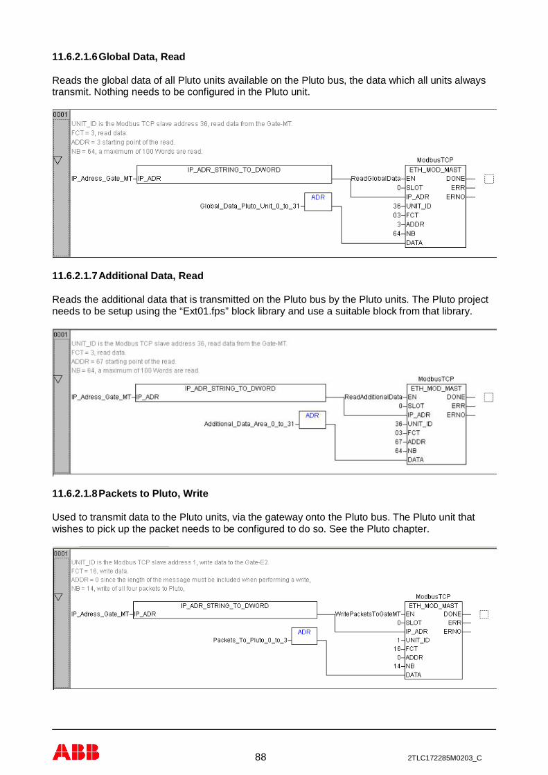
88 2TLC172285M0203_C
11.6.2.1.6 Global Data, Read
Reads the global data of all Pluto units available on the Pluto bus, the data which all units alwaystransmit. Nothing needs to be configured in the Pluto unit.
11.6.2.1.7 Additional Data, Read
Reads the additional data that is transmitted on the Pluto bus by the Pluto units. The Pluto projectneeds to be setup using the “Ext01.fps” block library and use a suitable block from that library.
11.6.2.1.8 Packets to Pluto, Write
Used to transmit data to the Pluto units, via the gateway onto the Pluto bus. The Pluto unit thatwishes to pick up the packet needs to be configured to do so. See the Pluto chapter.

89 2TLC172285M0203_C
11.6.2.2 Task configuration
Create a task under; Resources – Task configuration, calling the SFC POU at a suitable interval,for example as shown in the pictures.

90 2TLC172285M0203_C
12 Data to/from PlutoThis chapter will describe the different type of data sent to/from Pluto via the gateway. It will alsobe the reference chapter regarding encoding of the data.
12.1 Pluto Status
The size of this module is 4 bytes or 2 words. These data contain information about which Plutounits that are active on the Pluto bus. When a Pluto is active the corresponding bit is set to “1”.
The coding of the status data in byte is,Byte MSB LSB
0 Pluto 7 Pluto 6 Pluto 5 Pluto 4 Pluto 3 Pluto 2 Pluto 1 Pluto 01 Pluto 15 Pluto 14 Pluto 13 Pluto 12 Pluto 11 Pluto 10 Pluto 9 Pluto 82 Pluto 23 Pluto 22 Pluto 21 Pluto 20 Pluto 19 Pluto 18 Pluto 17 Pluto 163 Pluto 31 Pluto 30 Pluto 29 Pluto 28 Pluto 27 Pluto 26 Pluto 25 Pluto 24
Table 32, Pluto Status coding.
12.2 Global Data from Pluto
When selected, the global Pluto variables are always transferred. There are 32 global Plutovariables from each Pluto and they are always available on the Pluto bus, 1024 for a full net with32 Pluto. All variables are bit variables.
The size of this module is 4 bytes or 2 words. Pluto global variables are of different types and aredepending on which type of Pluto the data is coming from. The table below list different type ofvariables and the following tables list the layout of data from different type of Pluto:
Ix.y Inputs data port y from Pluto x.Qx.y Safety outputs port y from Pluto x.
GMx.y Global memories y from Pluto x.ASIx.y Input AS-i safety slave y from Pluto x.
Table 33, Pluto variables.
The coding of the Pluto variables for Pluto A20 and Double family in byte is,Byte MSB LSB
0 Ix.7 Ix.6 Ix.5 Ix.4 Ix.3 Ix.2 Ix.1 Ix.01 Ix.17 Ix.16 Ix.15 Ix.14 Ix.13 Ix.12 Ix.11 Ix.102 GMx.3 GMx.2 GMx.1 GMx.0 Qx.3 Qx.2 Qx.1 Qx.03 GMx.11 GMx.10 GMx.9 GMx.8 GMx.7 GMx.6 GMx.5 GMx.4
Table 34, Pluto global data for Pluto A20 and Double family (x is Pluto node number).
The coding of the status variables for Pluto AS-i family in byte is,Byte MSB LSB
0 ASIx.7 ASIx.6 ASIx.5 ASIx.4 ASIx.3 ASIx.2 ASIx.1 Ix.01 ASIx.15 ASIx.14 ASIx.13 ASIx.12 ASIx.11 ASIx.10 ASIx.9 ASIx.82 GMx.3 GMx.2 GMx.1 GMx.0 Qx.3 Qx.2 Qx.1 Qx.03 GMx.11 GMx.10 GMx.9 GMx.8 GMx.7 GMx.6 GMx.5 GMx.4
Table 35, Pluto global data for Pluto AS-i family (x is Pluto node number and ASIx.y is the safety node y).
The coding of the Pluto variables for Pluto B42 AS-i in byte is,Byte MSB LSB
0 GMx.3 GMx.2 GMx.1 GMx.0 Ix.3 Ix.2 Ix.1 Ix.01 GMx.11 GMx.10 GMx.9 GMx.8 GMx.7 GMx.6 GMx.5 GMx.42 GMx.19 GMx.18 GMx.17 GMx.16 GMx.15 GMx.14 GMx.13 GMx.123 GMx.27 GMx.26 GMx.25 GMx.24 GMx.23 GMx.22 GMx.21 GMx.20
Table 36, Pluto global data for Pluto B42 AS-i (x is Pluto node number).
The coding of the Pluto variables for Pluto O2 in byte is,

91 2TLC172285M0203_C
Byte MSB LSB0 - - - - - - Ix.1 Ix.01 - - - - - - Ix.11 Ix.102 GMx.3 GMx.2 GMx.1 GMx.0 - - Qx.1 Qx.03 GMx.11 GMx.10 GMx.9 GMx.8 GMx.7 GMx.6 GMx.5 GMx.4
Table 37, Pluto global data for Pluto O2 (x is Pluto node number).
12.3 Additional Data from Pluto
Every Pluto on the Pluto bus can send out additional data blocks where each block has:- The Pluto node number.- An IO-type number (for user block a user identity number).
- 0 (zero) data is not used.- 1-99 are user defined numbers used at the additional data blocks in PLC code.- ≥100 are standard additional data types (see tables below).- 111 are IO-type for Pluto global data.
- 32 bit of data according to IO-type.
The configuration of the additional data is normally done using application objects on the industryprotocol from the connected PLC system. It can also be done via the terminal port usingcommands according to chapter 0.
12.3.1 Layout of additional data
All blocks which can be used in the Pluto PLC program for sending additional data are listed below.
Note: For the user defined blocks each block in each Pluto must beallocated a unique number between 1 and 99 (on input “No”) to identify thedata block. This number is then used to identify the block in the receivingfield bus system.
The standard blocks have defined data.
12.3.1.1 User defined blocks
User defined “ToGateway_User_A” (ToGateway_UserNumber_x),Byte MSB LSB
0 Reg_0.7 Reg_0.6 Reg_0.5 Reg_0.4 Reg_0.3 Reg_0.2 Reg_0.1 Reg_0.01 Reg_0.15 Reg_0.14 Reg_0.13 Reg_0.12 Reg_0.11 Reg_0.10 Reg_0.9 Reg_0.82 Reg_1.7 Reg_1.6 Reg_1.5 Reg_1.4 Reg_1.3 Reg_1.2 Reg_1.1 Reg_1.03 Reg_1.15 Reg_1.14 Reg_1.13 Reg_1.12 Reg_1.11 Reg_1.10 Reg_1.9 Reg_1.8
Table 38, User defined block type A (Unique user number (x) set in block).
User defined “ToGateway_User_B” (ToGateway_UserNumber_x),Byte MSB LSB
0 Reg_0.7 Reg_0.6 Reg_0.5 Reg_0.4 Reg_0.3 Reg_0.2 Reg_0.1 Reg_0.01 Reg_0.15 Reg_0.14 Reg_0.13 Reg_0.12 Reg_0.11 Reg_0.10 Reg_0.9 Reg_0.82 Bit_7 Bit_6 Bit_5 Bit_4 Bit_3 Bit_2 Bit_1 Bit_03 Pluto Error Code
Table 39, User defined block type B (Unique user number (x) set in block).
User defined “ToGateway_User_C” (ToGateway_UserNumber_x),Byte MSB LSB
0 Reg_0.7 Reg_0.6 Reg_0.5 Reg_0.4 Reg_0.3 Reg_0.2 Reg_0.1 Reg_0.01 Reg_0.15 Reg_0.14 Reg_0.13 Reg_0.12 Reg_0.11 Reg_0.10 Reg_0.9 Reg_0.82 Bit_7 Bit_6 Bit_5 Bit_4 Bit_3 Bit_2 Bit_1 Bit_03 Bit_15 Bit_14 Bit_13 Bit_12 Bit_11 Bit_10 Bit_9 Bit_8
Table 40, User defined block type C (Unique user number (x) set in block).

92 2TLC172285M0203_C
12.3.1.2 Standard blocks
ASIx.y is safety slave y from Pluto AS-i unit (x is Pluto node number).
Standard “ToGateway_ErrorCode” (IO-type number 100, 0x64),Byte MSB LSB
0 - - - - - - - -1 - - - - - - - -2 - - - - - - - -3 Pluto Error Code
Table 41, Standard block “ToGateway_ErrorCode” ( ‘-‘ character indicate undefined value).
Standard “ToGateway_B46_I20_I47” (IO-type number 101, 0x65),Byte MSB LSB
0 Ix.27 Ix.26 Ix.25 Ix.24 Ix.23 Ix.22 Ix.21 Ix.201 Ix.37 Ix.36 Ix.35 Ix.34 Ix.33 Ix.32 Ix.31 Ix.302 Ix.47 Ix.46 Ix.45 Ix.44 Ix.43 Ix.42 Ix.41 Ix.403 Pluto Error Code
Table 42, Standard block “ToGateway_B46_I20_I47”.
Standard “ToGateway_ASi_16_31_Safe” (IO-type number 102, 0x66),Byte MSB LSB
0 Ix.13* Ix.12* Ix.11* Ix.10* Ix.3* Ix.2* Ix.1* -1 ASIx.23 ASIx.22 ASIx.21 ASIx.20 ASIx.19 ASIx.18 ASIx.17 ASIx.162 ASIx.31 ASIx.30 ASIx.29 ASIx.28 ASIx.27 ASIx.26 ASIx.25 ASIx.243 Pluto Error Code
Table 43, Standard block “ToGateway_ASi_16_31_Safe” ( ‘-‘ undefined value / ‘*’ undefined for B42 AS-i).
Standard “ToGateway_ASi_1_3_NonSafe_In” (IO-type number 103, 0x67),Byte MSB LSB
0 - - - - - - - -1 Ax.1B.4 Ax.1B.3 Ax.1B.2 Ax.1B.1 Ax.1.4 Ax.1.3 Ax.1.2 Ax.1.12 Ax.2B.4 Ax.2B.3 Ax.2B.2 Ax.2B.1 Ax.2.4 Ax.2.3 Ax.2.2 Ax.2.13 Ax.3B.4 Ax.3B.3 Ax.3B.2 Ax.3B.1 Ax.3.4 Ax.3.3 Ax.3.2 Ax.3.1
Table 44, Standard block “ToGateway_ASi_1_3_NonSafe_In” ( ‘-‘ undefined value).
Standard “ToGateway_ASi_4_7_NonSafe_In” (IO-type number 104, 0x68),Byte MSB LSB
0 Ax.4B.4 Ax.4B.3 Ax.4B.2 Ax.4B.1 Ax.4.4 Ax.4.3 Ax.4.2 Ax.4.11 Ax.5B.4 Ax.5B.3 Ax.5B.2 Ax.5B.1 Ax.5.4 Ax.5.3 Ax.5.2 Ax.5.12 Ax.6B.4 Ax.6B.3 Ax.6B.2 Ax.6B.1 Ax.6.4 Ax.6.3 Ax.6.2 Ax.6.13 Ax.7B.4 Ax.7B.3 Ax.7B.2 Ax.7B.1 Ax.7.4 Ax.7.3 Ax.7.2 Ax.7.1
Table 45, Standard block “ToGateway_ASi_4_7_NonSafe_In”.
Standard “ToGateway_ASi_8_11_NonSafe_In” (IO-type number 105, 0x69),Byte MSB LSB
0 Ax.8B.4 Ax.8B.3 Ax.8B.2 Ax.8B.1 Ax.8.4 Ax.8.3 Ax.8.2 Ax.8.11 Ax.9B.4 Ax.9B.3 Ax.9B.2 Ax.9B.1 Ax.9.4 Ax.9.3 Ax.9.2 Ax.9.12 Ax.10B.4 Ax.10B.3 Ax.10B.2 Ax.10B.1 Ax.10.4 Ax.10.3 Ax.10.2 Ax.10.13 Ax.11B.4 Ax.11B.3 Ax.11B.2 Ax.11B.1 Ax.11.4 Ax.11.3 Ax.11.2 Ax.11.1
Table 46, Standard block “ToGateway_ASi_8_11_NonSafe_In”.

93 2TLC172285M0203_C
Standard “ToGateway_ASi_12_15_NonSafe_In” (IO-type number 106, 0x6A),Byte MSB LSB
0 Ax.12B.4 Ax.12B.3 Ax.12B.2 Ax.12B.1 Ax.12.4 Ax.12.3 Ax.12.2 Ax.12.11 Ax.13B.4 Ax.13B.3 Ax.13B.2 Ax.13B.1 Ax.13.4 Ax.13.3 Ax.13.2 Ax.13.12 Ax.14B.4 Ax.14B.3 Ax.14B.2 Ax.14B.1 Ax.14.4 Ax.14.3 Ax.14.2 Ax.14.13 Ax.15B.4 Ax.15B.3 Ax.15B.2 Ax.15B.1 Ax.15.4 Ax.15.3 Ax.15.2 Ax.15.1
Table 47, Standard block “ToGateway_ASi_12_15_NonSafe_In”.
Standard “ToGateway_ASi_16_19_NonSafe_In” (IO-type number 107, 0x6B),Byte MSB LSB
0 Ax.16B.4 Ax.16B.3 Ax.16B.2 Ax.16B.1 Ax.16.4 Ax.16.3 Ax.16.2 Ax.16.11 Ax.17B.4 Ax.17B.3 Ax.17B.2 Ax.17B.1 Ax.17.4 Ax.17.3 Ax.17.2 Ax.17.12 Ax.18B.4 Ax.18B.3 Ax.18B.2 Ax.18B.1 Ax.18.4 Ax.18.3 Ax.18.2 Ax.18.13 Ax.19B.4 Ax.19B.3 Ax.19B.2 Ax.19B.1 Ax.19.4 Ax.19.3 Ax.19.2 Ax.19.1
Table 48, Standard block “ToGateway_ASi_16_19_NonSafe_In”.
Standard “ToGateway_ASi_20_23_NonSafe_In” (IO-type number 108, 0x6C),Byte MSB LSB
0 Ax.20B.4 Ax.20B.3 Ax.20B.2 Ax.20B.1 Ax.20.4 Ax.20.3 Ax.20.2 Ax.20.11 Ax.21B.4 Ax.21B.3 Ax.21B.2 Ax.21B.1 Ax.21.4 Ax.21.3 Ax.21.2 Ax.21.12 Ax.22B.4 Ax.22B.3 Ax.22B.2 Ax.22B.1 Ax.22.4 Ax.22.3 Ax.22.2 Ax.22.13 Ax.23B.4 Ax.23B.3 Ax.23B.2 Ax.23B.1 Ax.23.4 Ax.23.3 Ax.23.2 Ax.23.1
Table 49, Standard block “ToGateway_ASi_20_23_NonSafe_In”.
Standard “ToGateway_ASi_24_27_NonSafe_In” (IO-type number 109, 0x6D),Byte MSB LSB
0 Ax.24B.4 Ax.24B.3 Ax.24B.2 Ax.24B.1 Ax.24.4 Ax.24.3 Ax.24.2 Ax.24.11 Ax.25B.4 Ax.25B.3 Ax.25B.2 Ax.25B.1 Ax.25.4 Ax.25.3 Ax.25.2 Ax.25.12 Ax.26B.4 Ax.26B.3 Ax.26B.2 Ax.26B.1 Ax.26.4 Ax.26.3 Ax.26.2 Ax.26.13 Ax.27B.4 Ax.27B.3 Ax.27B.2 Ax.27B.1 Ax.27.4 Ax.27.3 Ax.27.2 Ax.27.1
Table 50, Standard block “ToGateway_ASi_24_27_NonSafe_In”.
Standard “ToGateway_ASi_28_31_NonSafe_In” (IO-type number 110, 0x6E),Byte MSB LSB
0 Ax.28B.4 Ax.28B.3 Ax.28B.2 Ax.28B.1 Ax.28.4 Ax.28.3 Ax.28.2 Ax.28.11 Ax.29B.4 Ax.29B.3 Ax.29B.2 Ax.29B.1 Ax.29.4 Ax.29.3 Ax.29.2 Ax.29.12 Ax.30B.4 Ax.30B.3 Ax.30B.2 Ax.30B.1 Ax.30.4 Ax.30.3 Ax.30.2 Ax.30.13 Ax.31B.4 Ax.31B.3 Ax.31B.2 Ax.31B.1 Ax.31.4 Ax.31.3 Ax.31.2 Ax.31.1
Table 51, Standard block “ToGateway_ASi_28_31_NonSafe_In”.
Standard “GLOBAL DATA” (IO-type number 111, 0x6F),Byte MSB LSB
0
See 12.2123
Table 52, Standard block “GLOBAL DATA”.
Standard “ToGateway_B42_ASi_I20_I47” (IO-type number 112, 0x70),Byte MSB LSB
0 Ix.27 Ix.26 Ix.25 Ix.24 Ix.23 Ix.22 Ix.21 Ix.201 Ix.37 Ix.36 Ix.35 Ix.34 Ix.33 Ix.32 Ix.31 Ix.302 Ix.47 Ix.46 Ix.45 Ix.44 Ix.43 Ix.42 Ix.41 Ix.403 Pluto Error Code
Table 53, Standard block “ToGateway_B42_ASi_I20_I47”.

94 2TLC172285M0203_C
Standard “ToGateway_ASi_1_15_Safe” (IO-type number 113, 0x71),Byte MSB LSB
0 Ix.17 Ix.16 Ix.15 Ix.14 Ix.13 Ix.12 Ix.11 Ix.101 ASIx.7 ASIx.6 ASIx.5 ASIx.4 ASIx.3 ASIx.2 ASIx.1 02 ASIx.15 ASIx.14 ASIx.13 ASIx.12 ASIx.11 ASIx.10 ASIx.9 ASIx.83 Pluto Error Code
Table 54, Standard block “ToGateway_ASi_1_15_Safe”.
Standard “ToGateway_D45_I20_I47” (IO-type number 114, 0x71),Byte MSB LSB
0 0 Ix.26 Ix.25 Ix.24 Ix.23 Ix.22 Ix.21 Ix.201 Ix.37 Ix.36 Ix.35 Ix.34 Ix.33 Ix.32 Ix.31 Ix.302 Ix.47 Ix.46 Ix.45 Ix.44 Ix.43 Ix.42 Ix.41 Ix.403 Pluto Error Code
Table 55, Standard block “ToGateway_D45_I20_I47”.

95 2TLC172285M0203_C
12.3.2 Programming in Pluto PLC
12.3.2.1 Function block libraryTo use the function “Additional data from Pluto” the function block library “Ext01_1.fps” must beselected. The library contains all blocks listed above (12.3.1.1 and0).
Figure 90 – Add function library “Ext01_1.fps”.
12.3.2.2 Use of the function blocksAs described before there are standard blocks and user defined blocks. The standard blocks havea fixed content as for example “ToGateway_B46_I20_I47” transmitting the local inputs and errorcode of a Pluto B46. The user defined blocks have inputs for bit variables (M, I, Q...) and registerswhich makes it possible for the user to compose his own telegram.
Each block generates a CAN telegram on thePluto bus. In order to control and limit bus loadand execution time all blocks have an inputnamed “Send”. When the input conditions for“Send” are true (1) the block transmits atelegram. All blocks have also an output “Q”which is high (1) by transmission and can forexample be used for inhibiting other blocks totransmit.
If “Send” is continuously activated a CAN message is transmitted every 10 ms which of course willgive the best performance in reaction time. If there is need for limiting the transmission depends onhow many Pluto units there are on the bus and how many of these blocks are used.
Note: Pluto can only send 4 telegrams every PLC cycle.
Note: Additional data can be sent with time interval up to 300 msas the internal timeout is fixed to 1000 ms.For example can the time interval be set by using timer blockTON, see example below, which then will to lower the busload if this update time is appropriate for the application.
Figure 91 – Example of a standard block.Transmission of AS-i slave inputs 16-31 and errorcode.
.
Figure 92 – Example of a user defined block:Transmission of 8 bits and one register.Note: Each block in each Pluto shall have its uniquenumber in input “No”.

96 2TLC172285M0203_C
12.3.2.3 Example of usage in Pluto programThe following two examples show how transmission rate can be controlled in order to limit the CANbus load and program execution time in Pluto.
Figure 93 – Example 1: Transmission of local IO:s in a Pluto B46 user defined block. The input “Send” in the first block isconnected to the system memory for 10Hz to decrease the CAN bus load to 1 telegram / 100ms. The second block will betransmitted one PLC cycle after the first because “Send” is connected to negative edge of Sent_1.”.

97 2TLC172285M0203_C
Figure 94 – Example for transmission from a Pluto AS-i sequence. The transmission can be enabled by memoryM0.0 in sequence 0 then a telegram will be transmitted every 50 ms. This is a recommended method when a lotof blocks are used since it limits the CAN bus load and the Pluto do not need to execute the code in inactivesequence steps.

98 2TLC172285M0203_C
12.4 Data to Pluto
A gateway can totally transfer 64 bit variables and 8 registers from other field buses to the Plutobus. The area “Data to Pluto” is divided into four packets each with16 bit variables and tworegisters and is organized according to the table below.
To Pluto Area Packet
Type Data
0 Bit (16 bits) Bit variables 0…15Register (16 bits) Register 0Register (16 bits) Register 1
1 Bit (16 bits) Bit variables 0…15Register (16 bits) Register 0Register (16 bits) Register 1
2 Bit (16 bits) Bit variables 0…15Register (16 bits) Register 0Register (16 bits) Register 1
3 Bit (16 bits) Bit variables 0…15Register (16 bits) Register 0Register (16 bits) Register 1
Table 56, “Data to Pluto” data allocation.
12.4.1 Enable bit
A PLC system on the field bus can enable the usage of 0 to 4 of the packets for Data to Pluto, forexample enable the gateway to transfer the data in packet 0 and 1 to the units on the Pluto bus.The gateway then transmits one packet in one CAN telegram.
12.4.2 Cyclic transmission time
The gateway will transmit each data packet cyclically every 100 ms to the Pluto bus. The timeinterval is 4 – 255 ms with a default value of 100 ms.
Note: Low cycle time will load the Pluto bus more.Therefore this value shall not be set lower than neededand with consideration of the load of the Pluto bus.
12.4.3 Timeout time
A PLC system on the field bus can also set a timeout value time in the range of 0 – 60000 ms. Thedefault value is 0 which is the same as no timeout. If the gateway does not receive data telegramsfrom the field bus within the timeout time the data will be cleared and the gateway will transmit “0”.
12.5 In PLUTO - Reception of external data from gateway
A PLUTO has a corresponding data area for external communication divided in four data blockswhich enables each PLUTO unit to receive four packets of data from different sources e.g. fourdifferent gateways. A data block in a PLUTO is programmed to receive data from a certaingateway node number (0 – 15) and a certain packet number (0 – 15).
12.5.1 Set up in PLUTO for reception
For each PLUTO which shall receive data from a gateway, a setup must be made to decide fromwhere the data comes. If the same gateway shall send to more than one block it must send in twodifferent packets. (One packet is one CAN telegram).

99 2TLC172285M0203_C
Note: The timeout shall be greater than the gateway cycle timewhich has a default value of 100 ms, see chapter 12.4.2.
12.5.2 Addressing of external data in Pluto
In the PLUTO the variables are numbered according to the following table.
Data block Data in PlutoExternal CommBlock 0
Data bit 0…15Register 0Register 1
External CommBlock 1
Data bit 16…31Register 2Register 3
External CommBlock 2
Data bit 32…47Register 4Register 5
External CommBlock 3
Data bit 48…63Register 6Register 7
Table 57, “Data to Pluto” external data in Pluto.
Figure 95 – Example of setup in Pluto for reception of external data fromthree different gateways.
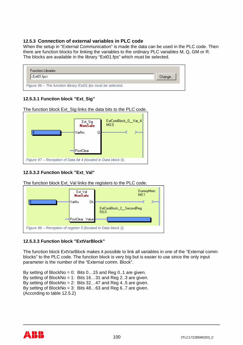
100 2TLC172285M0203_C
12.5.3 Connection of external variables in PLC codeWhen the setup in “External Communication” is made the data can be used in the PLC code. Thenthere are function blocks for linking the variables to the ordinary PLC variables M, Q, GM or R.The blocks are available in the library “Ext01.fps” which must be selected.
12.5.3.1 Function block ”Ext_Sig”
The function block Ext_Sig links the data bits to the PLC code.
12.5.3.2 Function block ”Ext_Val”
The function block Ext_Val links the registers to the PLC code.
12.5.3.3 Function block ”ExtVarBlock”
The function block ExtVarBlock makes it possible to link all variables in one of the “External commblocks” to the PLC code. The function block is very big but is easier to use since the only inputparameter is the number of the “External comm. Block”.
By setting of BlockNo = 0: Bits 0…15 and Reg 0..1 are given.By setting of BlockNo = 1: Bits 16…31 and Reg 2..3 are given.By setting of BlockNo = 2: Bits 32…47 and Reg 4..5 are given.By setting of BlockNo = 3: Bits 48…63 and Reg 6..7 are given.(According to table 12.5.2)
Figure 96 – The function library Ext01.fps must be selected.
Figure 97 – Reception of Data bit 4 (located in Data block 0).
Figure 98 – Reception of register 5 (located in Data block 2).

101 2TLC172285M0203_C
Figure 99 – Reception of all variables in “External Comm Block” 0, (16 bits, 2 registers).

102 2TLC172285M0203_C
13 Technical data
13.1 Protocol specific data
GATE-EIP – EtherNet/IPInterface According to,
· ODVA, CIP Volume 1 Edition 3.16· ODVA, CIP Volume 2 EtherNet/IP Adaption of CIP Edition 1.17· Minimum RPI value of 10 ms.
Status indication Mod (Module) status and Net (Network) status.Default IP address DHCP.Service ports TCP/44818, UDP/2222 and UDP/44818 (see 7.4).
GATE-EC – EtherCATInterface According to
· IEC 61158 Part 2-6 Type 12 documents (ETG.1000 V1.0.3).· EtherCAT Protocol Enhancements (ETG.1020 V1.0.0).· Minimum cycle time is 500 µs.· The device support FoE (firmware update).· The device support EoE (remote server).
Status indication Run and Error status.Default IP address Master configured.Service ports -
GATE-S3 – Sercos IIIInterface According to:
· Communication Spec. V1.1.2.1.7 (March 30, 2009).· Sercos Communication Profile V1.1.2.1.1 (March 31, 2009).· Function Specific Profile IO V1.1.2.1.4 (May 11, 2009).· Internet Protocol Services V1.3.1 - 1.2 (February 10, 2011).· Minimum cycle time is 500 µs.
Status indication S3 status.Default IP address 192.168.0.100Service ports UDP/35021 (see 9.4).
GATE-PN – PROFINETInterface According to:
· Specification for PROFINET, Version 2.31.· IRT Top (“Red phase”) will be supported.· Minimum cycle time 2ms for RTC1 and 1ms for RTC3.
Status indication SF (System Failure) and BF (Bus Failure).Default IP address Master configured.Service ports UDP/161, UDP/34964 and UDP/49152 (see 10.6).
GATE-MT – Modbus TCPInterface According to:
· Modbus Application Protocol Specification, V1.1a. · Modbus Messaging on TCP/IP Implementation Guide, V1.0a.· Minimum 500 request per seconds for one steady openconnection with about 1 ms response time.· Maximum of 8 client connections.
Status indication RUN (Connection) and ERR (Error).Default IP address DHCP.Service ports TCP/502 (see 11.4).

103 2TLC172285M0203_C
13.2 Common data
Ethernet data and servicesInterface 2 port with 10/100 Mbit/s, half/full duplex.Status Link status and traffic status on each port.IP address Static, DHCP and BOOTP.
Set via terminal (PC port), not for GATE-EC and GATE-PN.Remote server Remote access (port 50100, changeable).
Pluto busPluto bus CAN (electrical insulation 500 VAC).Pluto bus speed 100, 125, 200, 250, 400, 500, 800 and 1000 kbit/s
(automatic speed detection).Status indication Pluto bus status vid LED (Pluto bus).
PC port (front connector)Setting 57600 bit/s, 8 bit data, 1 stop bit, no parity and no flow control.Cable (serial) Article number 2TLA020070R5600.Cable (USB) Article number 2TLA020070R5800.
Common dataDC power 24 VDC, -15% to +20%.Power consumption at24V
< 4.8 W< 0.2 A (recommended external fuse ≤ 6 A).
Electrical insulation 500 VAC for Pluto bus and Ethernet ports to DC power.Enclosure Width = 22.5 mm, height = 108 mm and depth = 114 mm.Mounting 35 mm DIN rail.Ambient air temperature -10 °C to + 55 ºC.Temperature,transportation and storage
-25 °C to + 55 ºC.
Operating altitude Up to 2000 meter.Humidity EN 60 204-1 50% at 40 ºC (ex 90% at 20 ºC).Degree of protection Enclosure IP 20 - IEC 60 529.
Terminals IP 20 - IEC 60 529.Approval
Figure 100 – Gateway mechanical dimensions.
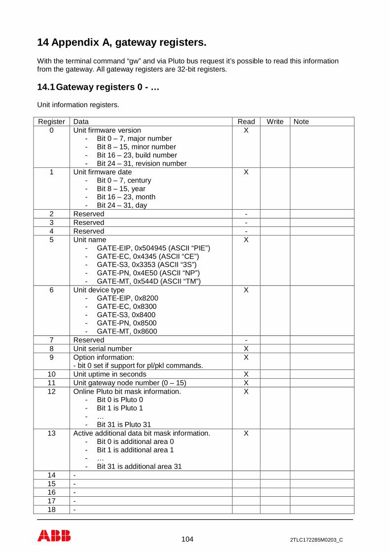
104 2TLC172285M0203_C
14 Appendix A, gateway registers.With the terminal command “gw” and via Pluto bus request it’s possible to read this informationfrom the gateway. All gateway registers are 32-bit registers.
14.1 Gateway registers 0 - …
Unit information registers.
Register Data Read Write Note0 Unit firmware version
- Bit 0 – 7, major number- Bit 8 – 15, minor number- Bit 16 – 23, build number- Bit 24 – 31, revision number
X
1 Unit firmware date- Bit 0 – 7, century- Bit 8 – 15, year- Bit 16 – 23, month- Bit 24 – 31, day
X
2 Reserved -3 Reserved -4 Reserved -5 Unit name
- GATE-EIP, 0x504945 (ASCII “PIE”)- GATE-EC, 0x4345 (ASCII “CE”)- GATE-S3, 0x3353 (ASCII “3S”)- GATE-PN, 0x4E50 (ASCII “NP”)- GATE-MT, 0x544D (ASCII “TM”)
X
6 Unit device type- GATE-EIP, 0x8200- GATE-EC, 0x8300- GATE-S3, 0x8400- GATE-PN, 0x8500- GATE-MT, 0x8600
X
7 Reserved -8 Unit serial number X9 Option information:
- bit 0 set if support for pl/pkl commands.X
10 Unit uptime in seconds X11 Unit gateway node number (0 – 15) X12 Online Pluto bit mask information.
- Bit 0 is Pluto 0- Bit 1 is Pluto 1- …- Bit 31 is Pluto 31
X
13 Active additional data bit mask information.- Bit 0 is additional area 0- Bit 1 is additional area 1- …- Bit 31 is additional area 31
X
14 -15 -16 -17 -18 -

105 2TLC172285M0203_C
19 -20 CAN speed (0 = speed detection) X21 CAN receive overrun counter X22 CAN error status X23 CAN error passive counter X24 CAN bus off counter X25 CAN restart counter X26 CAN RX counter (CAN controller) X27 CAN TX counter (CAN controller) X
14.2 Gateway registers 100 - …
Fieldbus information registers.
Register Data Read Write Note100 MAC address (high part, bit 0 - 15) X101 MAC address (low part, bit 0 - 31) X102 TCP/IP address
- aaa.bbb.ccc.ddd- bit 24 – 32 is aaa value- bit 16 – 23 is bbb value- bit 8 – 15 is ccc value- bit 0 – 7 is ddd value
X
103 TCP/IP subnet mask- See coding for register 102
X
104 TCP/IP gateway address- See coding for register 102
X
105 TCP/IP address mode- 1 address mode Static- 2 address mode BOOTP- 3 address mode DHCP
X
106 Number of Ethernet ports X107 Port speed for port 1
- 1 is 10 Mbit/s- 2 is 100 Mbit/s- Else undefined
X
108 Port speed for port 2- See coding for register 107
X
109 Port speed for port 3- See coding for register 107
X
110 Port speed for port 4- See coding for register 107
X
111 Duplex information for port 1- 1 is half duplex- 2 is full duplex- Else undefined
X
112 Duplex information for port 2- See coding for register 111
X
113 Duplex information for port 3- See coding for register 111
X
114 Duplex information for port 4- See coding for register 111
X
115 MAC address for port 1 (high part, bit 0 - 15) X GATE-PN116 MAC address for port 1 (low part, bit 0 - 31) X GATE-PN

106 2TLC172285M0203_C
117 MAC address for port 2 (high part, bit 0 - 15) X GATE-PN118 MAC address for port 2 (low part, bit 0 - 31) X GATE-PN119 MAC address for port 3 (high part, bit 0 - 15) X GATE-PN120 MAC address for port 3 (low part, bit 0 - 31) X GATE-PN121 MAC address for port 4 (high part, bit 0 - 15) X GATE-PN122 MAC address for port 4 (low part, bit 0 - 31) X GATE-PN123 Remote server active
- 1 is active / 0 is not activeX
124 Remote server port number X125 Remote Pluto system control
- 1 is active / 0 is not activeX
125 Number of connections to remote server X127 Max number of connections to remote server X
GATE-EIP specific registers (EtherNet/IP).
150 Vendor id X151 Product number X152 Profile number X153 Module status X154 Network status X
GATE-EC specific registers (EtherCAT).
150 Vendor id X151 Product number X
GATE-S3 specific registers (Sercos III).
150 Vendor id X151 Product number X
GATE-PN specific registers (PROFINET).
150 Vendor id X151 Product number X
GATE-MT specific registers (Modbus TCP).
150 - -
14.3 Gateway register 200 - …
Pluto global data register information.
Register Data Read Write Note200 Global data from Pluto 0 X201 Global data from Pluto 1 X202 Global data from Pluto 2 X203 Global data from Pluto 3 X204 Global data from Pluto 4 X205 Global data from Pluto 5 X206 Global data from Pluto 6 X207 Global data from Pluto 7 X
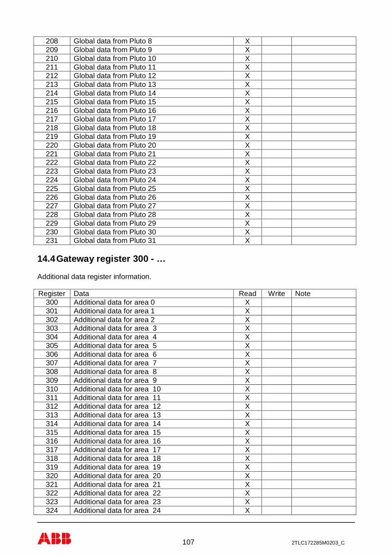
107 2TLC172285M0203_C
208 Global data from Pluto 8 X209 Global data from Pluto 9 X210 Global data from Pluto 10 X211 Global data from Pluto 11 X212 Global data from Pluto 12 X213 Global data from Pluto 13 X214 Global data from Pluto 14 X215 Global data from Pluto 15 X216 Global data from Pluto 16 X217 Global data from Pluto 17 X218 Global data from Pluto 18 X219 Global data from Pluto 19 X220 Global data from Pluto 20 X221 Global data from Pluto 21 X222 Global data from Pluto 22 X223 Global data from Pluto 23 X224 Global data from Pluto 24 X225 Global data from Pluto 25 X226 Global data from Pluto 26 X227 Global data from Pluto 27 X228 Global data from Pluto 28 X229 Global data from Pluto 29 X230 Global data from Pluto 30 X231 Global data from Pluto 31 X
14.4 Gateway register 300 - …
Additional data register information.
Register Data Read Write Note300 Additional data for area 0 X301 Additional data for area 1 X302 Additional data for area 2 X303 Additional data for area 3 X304 Additional data for area 4 X305 Additional data for area 5 X306 Additional data for area 6 X307 Additional data for area 7 X308 Additional data for area 8 X309 Additional data for area 9 X310 Additional data for area 10 X311 Additional data for area 11 X312 Additional data for area 12 X313 Additional data for area 13 X314 Additional data for area 14 X315 Additional data for area 15 X316 Additional data for area 16 X317 Additional data for area 17 X318 Additional data for area 18 X319 Additional data for area 19 X320 Additional data for area 20 X321 Additional data for area 21 X322 Additional data for area 22 X323 Additional data for area 23 X324 Additional data for area 24 X

108 2TLC172285M0203_C
325 Additional data for area 25 X326 Additional data for area 26 X327 Additional data for area 27 X328 Additional data for area 28 X329 Additional data for area 29 X330 Additional data for area 30 X331 Additional data for area 31 X
14.5 Gateway register 400 - …
Additional filter register information.- Bit 0 – 7 coding IO-type- Bit 8 – 15 coding Pluto number- Bit 30 set if active on Pluto bus- Bit 31 set if configuration active (e.g. IO-type not zero)
Register Data Read Write Note400 Additional filter for area 0 X401 Additional filter for area 1 X402 Additional filter for area 2 X403 Additional filter for area 3 X404 Additional filter for area 4 X405 Additional filter for area 5 X406 Additional filter for area 6 X407 Additional filter for area 7 X408 Additional filter for area 8 X409 Additional filter for area 9 X410 Additional filter for area 10 X411 Additional filter for area 11 X412 Additional filter for area 12 X413 Additional filter for area 13 X414 Additional filter for area 14 X415 Additional filter for area 15 X416 Additional filter for area 16 X417 Additional filter for area 17 X418 Additional filter for area 18 X419 Additional filter for area 19 X420 Additional filter for area 20 X421 Additional filter for area 21 X422 Additional filter for area 22 X423 Additional filter for area 23 X424 Additional filter for area 24 X425 Additional filter for area 25 X426 Additional filter for area 26 X427 Additional filter for area 27 X428 Additional filter for area 28 X429 Additional filter for area 29 X430 Additional filter for area 30 X431 Additional filter for area 31 X
14.6 Gateway register 500 - …
Data to Pluto data register information.
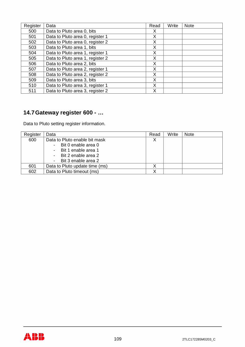
109 2TLC172285M0203_C
Register Data Read Write Note500 Data to Pluto area 0, bits X501 Data to Pluto area 0, register 1 X502 Data to Pluto area 0, register 2 X503 Data to Pluto area 1, bits X504 Data to Pluto area 1, register 1 X505 Data to Pluto area 1, register 2 X506 Data to Pluto area 2, bits X507 Data to Pluto area 2, register 1 X508 Data to Pluto area 2, register 2 X509 Data to Pluto area 3, bits X510 Data to Pluto area 3, register 1 X511 Data to Pluto area 3, register 2 X
14.7 Gateway register 600 - …
Data to Pluto setting register information.
Register Data Read Write Note600 Data to Pluto enable bit mask
- Bit 0 enable area 0- Bit 1 enable area 1- Bit 2 enable area 2- Bit 3 enable area 2
X
601 Data to Pluto update time (ms) X602 Data to Pluto timeout (ms) X

110 2TLC172285M0203_C
15 Appendix B, object description EtherNet/IPThis is a description of the object model used for EtherNet/IP.
15.1 Definitions
The following table has a description of all of the data types used.
USINT Unsigned Short Integer (8-bit)UINT Unsigned Integer (16-bit)UDINT Unsigned Double Integer (32-bit)STRING Character String (1 byte per character)BYTE Bit String (8-bits)WORD Bit String (16-bits)DWORD Bit String (32-bits)
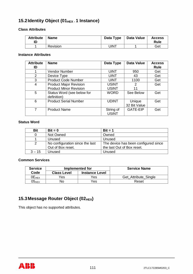
111 2TLC172285M0203_C
15.2 Identity Object (01HEX - 1 Instance)
Class Attributes
AttributeID
Name Data Type Data Value AccessRule
1 Revision UINT 1 Get
Instance Attributes
AttributeID
Name Data Type Data Value AccessRule
1 Vendor Number UINT 950 Get2 Device Type UINT 43 Get3 Product Code Number UINT 1100 Get4 Product Major Revision
Product Minor RevisionUSINTUSINT
211
Get
5 Status Word (see below fordefinition)
WORD See Below Get
6 Product Serial Number UDINT Unique32 Bit Value
Get
7 Product Name String ofUSINT
GATE-EIP Get
Status Word
Bit Bit = 0 Bit = 10 Not Owned Owned1 Unused Unused2 No configuration since the last
Out of Box reset.The device has been configured sincethe last Out of Box reset.
3 – 15 Unused Unused
Common Services
ServiceCode
Implemented for Service NameClass Level Instance Level
0EHEX Yes Yes Get_Attribute_Single05HEX No Yes Reset
15.3 Message Router Object (02HEX)
This object has no supported attributes.

112 2TLC172285M0203_C
15.4 Assembly Object (04HEX – 5 Instances)
Class Attributes (Instance 0)
AttributeID
Name Data Type Data Value AccessRule
1 Revision UINT 2 Get2 Max Instance UINT 113 Get
Input Instance Attributes (Instance 100 - 102)
AttributeID
Name Data Type DefaultData Value
AccessRule
3 Input Data USINT[4-132]
0 Get
Input Instance 100 – 4 Bytes (Node Status Only)
For more information about data structure see chapter 12.
Bytes Class, Instance, Attribute Description0 – 3 0x64, 0x00, 0B Node Status
Input Instance 101 – 256 Bytes (Node Data Only)
For more information about data structure see chapter 12.
Bytes Class, Instance, Attribute Description0 – 3 0x64, 0x01, 0x04 Combined 32 Bit Data – Node 04 – 7 0x64, 0x02, 0x04 Combined 32 Bit Data – Node 1…120 – 123 0x64, 0x1F, 0x04 Combined 32 Bit Data – Node 30124 – 127 0x64, 0x20, 0x04 Combined 32 Bit Data – Node 31128 – 131 0x64, 0x01, 0x0A Additional Data 00132 – 135 0x64, 0x02, 0x0A Additional Data 01…248 – 251 0x64, 0x1F, 0x0A Additional Data 30252 – 255 0x64, 0x20, 0x0A Additional Data 31

113 2TLC172285M0203_C
Input Instance 102 – 260 Bytes (Node Status and Data)
For more information about data structure see chapter 12.
Bytes Class, Instance, Attribute Description0 – 3 0x64, 0x00, 0x0B Node Status4 – 7 0x64, 0x01, 0x04 Combined 32 Bit Data – Node 08 – 11 0x64, 0x02, 0x04 Combined 32 Bit Data – Node 1…124 – 127 0x64, 0x1F, 0x04 Combined 32 Bit Data – Node 30128 – 131 0x64, 0x20, 0x04 Combined 32 Bit Data – Node 31132 – 135 0x64, 0x01, 0x0A Additional Data 00136 – 139 0x64, 0x02, 0x0A Additional Data 01…252 – 255 0x64, 0x1F, 0x0A Additional Data 30256 – 259 0x64, 0x20, 0x0A Additional Data 31
Output Instance Attributes (Instance 112)
AttributeID
Name Data Type DefaultData Value
AccessRule
3 Output Data USINT[0-24]
0 Get
Output Instance 112 – 24 Bytes (Data to Pluto)
For more information about data structure see chapter Error! Reference source not found..
Bytes Class, Instance, Attribute Description0 – 5 0x64, 0x00, 0x0C Data to Pluto area 06 – 11 0x64, 0x00, 0x0D Data to Pluto area 112 – 17 0x64, 0x00, 0x0E Data to Pluto area 218 – 23 0x64, 0x00, 0x0F Data to Pluto area 3
Output Instance 128 (Heartbeat Instance – Input Only)
This instance allows client to monitor input data without providing output data.
Output Instance 129 (Heartbeat Instance – Listen Only)
This instance allows client to monitor input data without providing output data. To utilize thisconnection type, an owning connection must exist from a second client and the configuration of theconnection must match exactly.
Output Instance 130 (Configuration Instance)
This instance allows client to download necessary configuration information to the gateway whenthe I/O connection is opened. The configuration instance supports 0 – 400 bytes of data. If noconfiguration data is needed this instance may be omitted.

114 2TLC172285M0203_C
Common Services
ServiceCode
Implemented for Service NameClass Level Instance Level
0EHEX Yes Yes Get_Attribute_Single10HEX No Yes Set_Attribute_Single
15.5 Connection Manager Object (06HEX)
This object has no attributes.
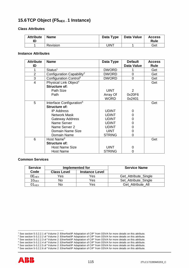
115 2TLC172285M0203_C
15.6 TCP Object (F5HEX - 1 Instance)
Class Attributes
AttributeID
Name Data Type Data Value AccessRule
1 Revision UINT 1 Get
Instance Attributes
AttributeID
Name Data Type DefaultData Value
AccessRule
1 Status1 DWORD 1 Get2 Configuration Capability2 DWORD 0 Get3 Configuration Control3 DWORD 0 Get4 Physical Link Object4
Structure of:Path Size
PathUINT
Array OfWORD
20x20F60x2401
Get
5 Interface Configuration5
Structure of: IP Address Network Mask Gateway Address Name Server Name Server 2 Domain Name Size Domain Name
UDINTUDINTUDINTUDINTUDINTUINT
STRING
0000000
Get
6 Host Name6
Structure of: Host Name Size Host Name
UINTSTRING
00
Get
Common Services
ServiceCode
Implemented for Service NameClass Level Instance Level
0EHEX Yes Yes Get_Attribute_Single10HEX No Yes Set_Attribute_Single01HEX No Yes Get_Attribute_All
1 See section 5-3.2.2.1 of “Volume 2: EtherNet/IP Adaptation of CIP” from ODVA for more details on this attribute.2 See section 5-3.2.2.2 of “Volume 2: EtherNet/IP Adaptation of CIP” from ODVA for more details on this attribute.3 See section 5-3.2.2.3 of “Volume 2: EtherNet/IP Adaptation of CIP” from ODVA for more details on this attribute.4 See section 5-3.2.2.4 of “Volume 2: EtherNet/IP Adaptation of CIP” from ODVA for more details on this attribute.5 See section 5-3.2.2.5 of “Volume 2: EtherNet/IP Adaptation of CIP” from ODVA for more details on this attribute.6 See section 5-3.2.2.6 of “Volume 2: EtherNet/IP Adaptation of CIP” from ODVA for more details on this attribute.

116 2TLC172285M0203_C
15.7 Ethernet Link Object (F6HEX - 1 Instance)
Class Attributes
Attribute ID Name Data Type Data Value AccessRule
1 Revision UINT 1 Get
Instance Attributes
Attribute ID Name Data Type DefaultData Value
AccessRule
1 Interface Speed7 UDINT 100 Get2 Interface Flags8 DWORD 3 Get3 Physical Address9 USINT
Array[6]0 Get
Common Services
ServiceCode
Implemented for Service NameClass Level Instance Level
0EHEX Yes Yes Get_Attribute_Single01HEX No Yes Get_Attribute_All
7 See section 5-4.2.2.1 of “Volume 2: EtherNet/IP Adaptation of CIP” from ODVA for more details on this attribute.8 See section 5-4.2.2.2 of “Volume 2: EtherNet/IP Adaptation of CIP” from ODVA for more details on this attribute.9 See section 5-4.2.2.3 of “Volume 2: EtherNet/IP Adaptation of CIP” from ODVA for more details on this attribute.

117 2TLC172285M0203_C
15.8 Application Object (64HEX - 32 Instances)
Class Attributes (Instance 0)
For more information about “Data to Pluto” structure see chapter 12.4.
Attribute ID Name Data Type DefaultData Value
AccessRule
1 Revision UINT 1 Get10 Expected Nodes Bitmap
Not used!DWORD 0 Get/Set
11 Node Status Bitmap DWORD 0 Get12 Data to Pluto 1 UINT[3] 0,0,0 Get/Set13 Data to Pluto 2 UINT[3] 0,0,0 Get/Set14 Data to Pluto 3 UINT[3] 0,0,0 Get/Set15 Data to Pluto 4 UINT[3] 0,0,0 Get/Set16 Enable Data to Pluto
(0 = Disabled; 1 = Enabled) Bit 0 – Data To Pluto 1 Bit 1 – Data To Pluto 2 Bit 2 – Data To Pluto 3 Bit 3 – Data To Pluto 4
BYTE 0 Get/Set
17 Data to Pluto Timeout (ms)0 = timeout disabledValid value ≥ 1000 ms.
UINT16 0 Get/Set
18 Data to Pluto Update Time(ms). Value modulus of 4 e.g.0, 4, 8, 16… 252.
UINT8 100 Get/Set
19 Set gateway node number0 = DIP switch setting1 = Node number 02 = Node number 1…16 = Node number 15
UINT8 0 Get/Set
20 Read gateway node number0 = Node number 01 = Node number 1…15 = Node number 15
UINT8 0 Get
Additional data configuration see chapter 12.3.
Attribute ID Name Data Type DefaultData Value
AccessRule
32 Additional Data 00, Node (0-31) BYTE 0 Get/Set33 Additional Data 00, IO-type BYTE 0 Get/Set34 Additional Data 01, Node (0-31) BYTE 0 Get/Set35 Additional Data 01, IO-type BYTE 0 Get/Set36 Additional Data 02, Node (0-31) BYTE 0 Get/Set37 Additional Data 02, IO-type BYTE 0 Get/Set38 Additional Data 03, Node (0-31) BYTE 0 Get/Set39 Additional Data 03, IO-type BYTE 0 Get/Set40 Additional Data 04, Node (0-31) BYTE 0 Get/Set41 Additional Data 04, IO-type BYTE 0 Get/Set42 Additional Data 05, Node (0-31) BYTE 0 Get/Set43 Additional Data 05, IO-type BYTE 0 Get/Set

118 2TLC172285M0203_C
44 Additional Data 06, Node (0-31) BYTE 0 Get/Set45 Additional Data 06, IO-type BYTE 0 Get/Set46 Additional Data 07, Node (0-31) BYTE 0 Get/Set47 Additional Data 07, IO-type BYTE 0 Get/Set48 Additional Data 08, Node (0-31) BYTE 0 Get/Set49 Additional Data 08, IO-type BYTE 0 Get/Set50 Additional Data 09, Node (0-31) BYTE 0 Get/Set51 Additional Data 09, IO-type BYTE 0 Get/Set52 Additional Data 10, Node (0-31) BYTE 0 Get/Set53 Additional Data 10, IO-type BYTE 0 Get/Set54 Additional Data 11, Node (0-31) BYTE 0 Get/Set55 Additional Data 11, IO-type BYTE 0 Get/Set56 Additional Data 12, Node (0-31) BYTE 0 Get/Set57 Additional Data 12, IO-type BYTE 0 Get/Set58 Additional Data 13, Node (0-31) BYTE 0 Get/Set59 Additional Data 13, IO-type BYTE 0 Get/Set60 Additional Data 14, Node (0-31) BYTE 0 Get/Set61 Additional Data 14, IO-type BYTE 0 Get/Set62 Additional Data 15, Node (0-31) BYTE 0 Get/Set63 Additional Data 15, IO-type BYTE 0 Get/Set64 Additional Data 16, Node (0-31) BYTE 0 Get/Set65 Additional Data 16, IO-type BYTE 0 Get/Set66 Additional Data 17, Node (0-31) BYTE 0 Get/Set67 Additional Data 17, IO-type BYTE 0 Get/Set68 Additional Data 18, Node (0-31) BYTE 0 Get/Set69 Additional Data 18, IO-type BYTE 0 Get/Set70 Additional Data 19, Node (0-31) BYTE 0 Get/Set71 Additional Data 19, IO-type BYTE 0 Get/Set72 Additional Data 20, Node (0-31) BYTE 0 Get/Set73 Additional Data 20, IO-type BYTE 0 Get/Set74 Additional Data 21, Node (0-31) BYTE 0 Get/Set75 Additional Data 21, IO-type BYTE 0 Get/Set76 Additional Data 22, Node (0-31) BYTE 0 Get/Set77 Additional Data 22, IO-type BYTE 0 Get/Set78 Additional Data 23, Node (0-31) BYTE 0 Get/Set79 Additional Data 23, IO-type BYTE 0 Get/Set80 Additional Data 24, Node (0-31) BYTE 0 Get/Set81 Additional Data 24, IO-type BYTE 0 Get/Set82 Additional Data 25, Node (0-31) BYTE 0 Get/Set83 Additional Data 25, IO-type BYTE 0 Get/Set84 Additional Data 26, Node (0-31) BYTE 0 Get/Set85 Additional Data 26, IO-type BYTE 0 Get/Set86 Additional Data 27, Node (0-31) BYTE 0 Get/Set87 Additional Data 27, IO-type BYTE 0 Get/Set88 Additional Data 28, Node (0-31) BYTE 0 Get/Set89 Additional Data 28, IO-type BYTE 0 Get/Set90 Additional Data 29, Node (0-31) BYTE 0 Get/Set91 Additional Data 29, IO-type BYTE 0 Get/Set92 Additional Data 30, Node (0-31) BYTE 0 Get/Set93 Additional Data 30, IO-type BYTE 0 Get/Set94 Additional Data 31, Node (0-31) BYTE 0 Get/Set95 Additional Data 31, IO-type BYTE 0 Get/Set
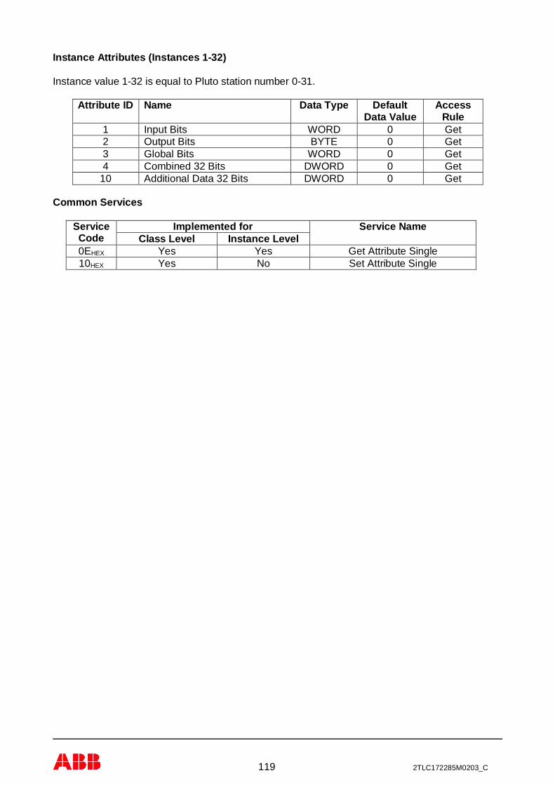
119 2TLC172285M0203_C
Instance Attributes (Instances 1-32)
Instance value 1-32 is equal to Pluto station number 0-31.
Attribute ID Name Data Type DefaultData Value
AccessRule
1 Input Bits WORD 0 Get2 Output Bits BYTE 0 Get3 Global Bits WORD 0 Get4 Combined 32 Bits DWORD 0 Get
10 Additional Data 32 Bits DWORD 0 Get
Common Services
ServiceCode
Implemented for Service NameClass Level Instance Level
0EHEX Yes Yes Get Attribute Single10HEX Yes No Set Attribute Single

120 2TLC172285M0203_C
16 Appendix C, object description EtherCAT
16.1 PDO mapping
16.1.1 Input mapping
16.1.1.1 Pluto status (0x1A00)
Index:Subindex
Name Data Type Default DataValue
Access
0x1A00:1 Pluto status data(0x2120:1)
16.1.1.2 Pluto global 0 – 7 (0x1A01)
Index:Subindex
Name Data Type Default DataValue
Access
0x1A01:1 Pluto global 0 (0x2100:1)
0x1A01:2 Pluto global 1 (0x2100:2)
0x1A01:3 Pluto global 2 (0x2100:3)
0x1A01:4 Pluto global 3 (0x2100:4)
0x1A01:5 Pluto global 4 (0x2100:5)
0x1A01:6 Pluto global 5 (0x2100:6)
0x1A01:7 Pluto global 6 (0x2100:7)
0x1A01:8 Pluto global 7 (0x2100:8)
16.1.1.3 Pluto global 8 – 15 (0x1A02)
Index:Subindex
Name Data Type Default DataValue
Access
0x1A02:1 Pluto global 8 (0x2100:9)
0x1A02:2 Pluto global 9 (0x2100:10)
0x1A02:3 Pluto global 10 (0x2100:11)
0x1A02:4 Pluto global 11 (0x2100:12)
0x1A02:5 Pluto global 12 (0x2100:13)
0x1A02:6 Pluto global 13 (0x2100:14)
0x1A02:7 Pluto global 14 (0x2100:15)
0x1A02:8 Pluto global 15 (0x2100:16)
16.1.1.4 Pluto global 16 – 23 (0x1A03)
Index:Subindex
Name Data Type Default DataValue
Access
0x1A03:1 Pluto global 16 (0x2100:17)
0x1A03:2 Pluto global 17 (0x2100:18)
0x1A03:3 Pluto global 18 (0x2100:19)
0x1A03:4 Pluto global 19 (0x2100:20)

121 2TLC172285M0203_C
Index:Subindex
Name Data Type Default DataValue
Access
0x1A03:5 Pluto global 20 (0x2100:21)
0x1A03:6 Pluto global 21 (0x2100:22)
0x1A03:7 Pluto global 22 (0x2100:23)
0x1A03:8 Pluto global 23 (0x2100:24)
16.1.1.5 Pluto global 24 – 31 (0x1A04)
Index:Subindex
Name Data Type Default DataValue
Access
0x1A04:1 Pluto global 24 (0x2100:25)
0x1A04:2 Pluto global 25 (0x2100:26)
0x1A04:3 Pluto global 26 (0x2100:27)
0x1A04:4 Pluto global 27 (0x2100:28)
0x1A04:5 Pluto global 28 (0x2100:29)
0x1A04:6 Pluto global 29 (0x2100:30)
0x1A04:7 Pluto global 30 (0x2100:31)
0x1A04:8 Pluto global 31 (0x2100:31)
16.1.1.6 Additional data 0 – 7 (0x1A05)
Index:Subindex
Name Data Type Default DataValue
Access
0x1A05:1 Additional data 0 (0x2101:1)
0x1A05:2 Additional data 1 (0x2101:2)
0x1A05:3 Additional data 2 (0x2101:3)
0x1A05:4 Additional data 3 (0x2101:4)
0x1A05:5 Additional data 4 (0x2101:5)
0x1A05:6 Additional data 5 (0x2101:6)
0x1A05:7 Additional data 6 (0x2101:7)
0x1A05:8 Additional data 7 (0x2101:8)
16.1.1.7 Additional data 8 – 15 (0x1A06)
Index:Subindex
Name Data Type Default DataValue
Access
0x1A06:1 Additional data 8 (0x2101:9)
0x1A06:2 Additional data 9 (0x2101:10)
0x1A06:3 Additional data 10 (0x2101:11)
0x1A06:4 Additional data 11 (0x2101:12)
0x1A06:5 Additional data 12 (0x2101:13)
0x1A06:6 Additional data 13 (0x2101:14)
0x1A06:7 Additional data 14 (0x2101:15)

122 2TLC172285M0203_C
Index:Subindex
Name Data Type Default DataValue
Access
0x1A06:8 Additional data 15 (0x2101:16)
16.1.1.8 Additional data 16 – 23 (0x1A07)
Index:Subindex
Name Data Type Default DataValue
Access
0x1A07:1 Additional data 16 (0x2101:17)
0x1A07:2 Additional data 17 (0x2101:18)
0x1A07:3 Additional data 18 (0x2101:19)
0x1A07:4 Additional data 19 (0x2101:20)
0x1A07:5 Additional data 20 (0x2101:21)
0x1A07:6 Additional data 21 (0x2101:22)
0x1A07:7 Additional data 22 (0x2101:23)
0x1A07:8 Additional data 23 (0x2101:24)
16.1.1.9 Additional data 24 – 31 (0x1A08)
Index:Subindex
Name Data Type Default DataValue
Access
0x1A08:1 Additional data 24 (0x2101:25)
0x1A08:2 Additional data 25 (0x2101:26)
0x1A08:3 Additional data 26 (0x2101:27)
0x1A08:4 Additional data 27 (0x2101:28)
0x1A08:5 Additional data 28 (0x2101:29)
0x1A08:6 Additional data 29 (0x2101:30)
0x1A08:7 Additional data 30 (0x2101:31)
0x1A08:8 Additional data 31 (0x2101:31)
16.1.2 Output mapping
16.1.2.1 Data to Pluto packet 1 (0x1600)
Index:Subindex
Name Data Type Default DataValue
Access
0x1600:1 Bits 0-15 (0x2200:1)
0x1600:2 Register 0 (0x2200:2)
0x1600:3 Register 1 (0x2200:3)
16.1.2.2 Data to Pluto packet 1 (0x1601)
Index:Subindex
Name Data Type Default DataValue
Access
0x1601:1 Bits 0-15 (0x2201:1)

123 2TLC172285M0203_C
Index:Subindex
Name Data Type Default DataValue
Access
0x1601:2 Register 0 (0x2201:2)
0x1601:3 Register 1 (0x2201:3)
16.1.2.3 Data to Pluto packet 3 (0x1602)
Index:Subindex
Name Data Type Default DataValue
Access
0x1602:1 Bits 0-15 (0x2202:1)
0x1602:2 Register 0 (0x2202:2)
0x1602:3 Register 1 (0x2202:3)
16.1.2.4 Data to Pluto packet 4 (0x1603)
Index:Subindex
Name Data Type Default DataValue
Access
0x1603:1 Bits 0-15 (0x2203:1)
0x1603:2 Register 0 (0x2203:2)
0x1603:3 Register 1 (0x2203:3)
16.2 SDO mapping
16.2.1 Pluto global data (0x2100)
Index:Subindex
Name Data Type Default DataValue
Access
0x2100:1 Pluto 0 DWORD 0 Ro0x2100:2 Pluto 1 DWORD 0 Ro0x2100:3 Pluto 2 DWORD 0 Ro0x2100:4 Pluto 3 DWORD 0 Ro0x2100:5 Pluto 4 DWORD 0 Ro0x2100:6 Pluto 5 DWORD 0 Ro0x2100:7 Pluto 6 DWORD 0 Ro0x2100:8 Pluto 7 DWORD 0 Ro0x2100:9 Pluto 8 DWORD 0 Ro0x2100:10 Pluto 9 DWORD 0 Ro0x2100:11 Pluto 10 DWORD 0 Ro0x2100:12 Pluto 11 DWORD 0 Ro0x2100:13 Pluto 12 DWORD 0 Ro0x2100:14 Pluto 13 DWORD 0 Ro0x2100:15 Pluto 14 DWORD 0 Ro0x2100:16 Pluto 15 DWORD 0 Ro0x2100:17 Pluto 16 DWORD 0 Ro0x2100:18 Pluto 17 DWORD 0 Ro0x2100:19 Pluto 18 DWORD 0 Ro0x2100:20 Pluto 19 DWORD 0 Ro

124 2TLC172285M0203_C
Index:Subindex
Name Data Type Default DataValue
Access
0x2100:21 Pluto 20 DWORD 0 Ro0x2100:22 Pluto 21 DWORD 0 Ro0x2100:23 Pluto 22 DWORD 0 Ro0x2100:24 Pluto 23 DWORD 0 Ro0x2100:25 Pluto 24 DWORD 0 Ro0x2100:26 Pluto 25 DWORD 0 Ro0x2100:27 Pluto 26 DWORD 0 Ro0x2100:28 Pluto 27 DWORD 0 Ro0x2100:29 Pluto 28 DWORD 0 Ro0x2100:30 Pluto 29 DWORD 0 Ro0x2100:31 Pluto 30 DWORD 0 Ro0x2100:32 Pluto 31 DWORD 0 Ro
16.2.2 Additional data (0x2101)
Index:Subindex
Name Data Type Default DataValue
Access
0x2101:1 Additional area 0 DWORD 0 Ro0x2101:2 Additional area 1 DWORD 0 Ro0x2101:3 Additional area 2 DWORD 0 Ro0x2101:4 Additional area 3 DWORD 0 Ro0x2101:5 Additional area 4 DWORD 0 Ro0x2101:6 Additional area 5 DWORD 0 Ro0x2101:7 Additional area 6 DWORD 0 Ro0x2101:8 Additional area 7 DWORD 0 Ro0x2101:9 Additional area 8 DWORD 0 Ro0x2101:10 Additional area 9 DWORD 0 Ro0x2101:11 Additional area 10 DWORD 0 Ro0x2101:12 Additional area 11 DWORD 0 Ro0x2101:13 Additional area 12 DWORD 0 Ro0x2101:14 Additional area 13 DWORD 0 Ro0x2101:15 Additional area 14 DWORD 0 Ro0x2101:16 Additional area 15 DWORD 0 Ro0x2101:17 Additional area 16 DWORD 0 Ro0x2101:18 Additional area 17 DWORD 0 Ro0x2101:19 Additional area 18 DWORD 0 Ro0x2101:20 Additional area 19 DWORD 0 Ro0x2101:21 Additional area 20 DWORD 0 Ro0x2101:22 Additional area 21 DWORD 0 Ro0x2101:23 Additional area 22 DWORD 0 Ro0x2101:24 Additional area 23 DWORD 0 Ro0x2101:25 Additional area 24 DWORD 0 Ro0x2101:26 Additional area 25 DWORD 0 Ro0x2101:27 Additional area 26 DWORD 0 Ro0x2101:28 Additional area 27 DWORD 0 Ro0x2101:29 Additional area 28 DWORD 0 Ro
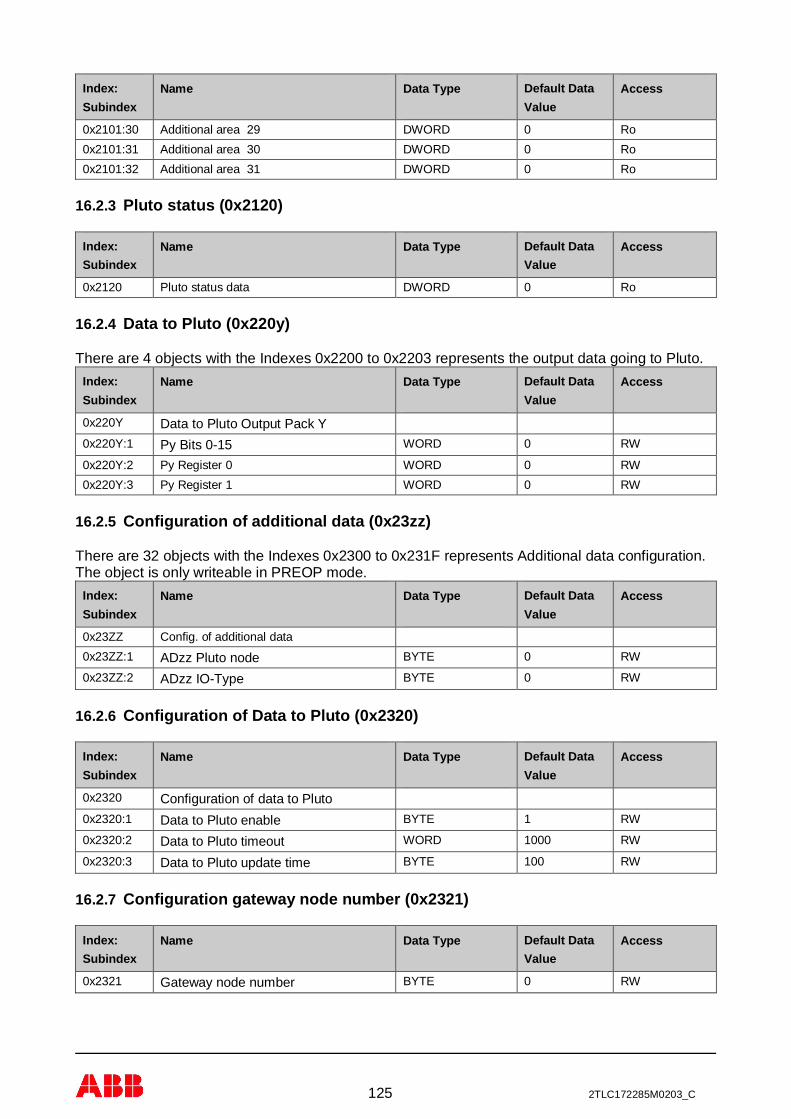
125 2TLC172285M0203_C
Index:Subindex
Name Data Type Default DataValue
Access
0x2101:30 Additional area 29 DWORD 0 Ro0x2101:31 Additional area 30 DWORD 0 Ro0x2101:32 Additional area 31 DWORD 0 Ro
16.2.3 Pluto status (0x2120)
Index:Subindex
Name Data Type Default DataValue
Access
0x2120 Pluto status data DWORD 0 Ro
16.2.4 Data to Pluto (0x220y)
There are 4 objects with the Indexes 0x2200 to 0x2203 represents the output data going to Pluto.Index:Subindex
Name Data Type Default DataValue
Access
0x220Y Data to Pluto Output Pack Y0x220Y:1 Py Bits 0-15 WORD 0 RW
0x220Y:2 Py Register 0 WORD 0 RW0x220Y:3 Py Register 1 WORD 0 RW
16.2.5 Configuration of additional data (0x23zz)
There are 32 objects with the Indexes 0x2300 to 0x231F represents Additional data configuration.The object is only writeable in PREOP mode.
Index:Subindex
Name Data Type Default DataValue
Access
0x23ZZ Config. of additional data0x23ZZ:1 ADzz Pluto node BYTE 0 RW
0x23ZZ:2 ADzz IO-Type BYTE 0 RW
16.2.6 Configuration of Data to Pluto (0x2320)
Index:Subindex
Name Data Type Default DataValue
Access
0x2320 Configuration of data to Pluto0x2320:1 Data to Pluto enable BYTE 1 RW
0x2320:2 Data to Pluto timeout WORD 1000 RW
0x2320:3 Data to Pluto update time BYTE 100 RW
16.2.7 Configuration gateway node number (0x2321)
Index:Subindex
Name Data Type Default DataValue
Access
0x2321 Gateway node number BYTE 0 RW

126 2TLC172285M0203_C
17 Appendix D, object description Sercos III
17.1 Standard Sercos IDN supported by the gateway
IDN Name Value Unit commentS-0-0014 Interface Status - -S-0-0017 IDN list of all operation data - -S-0-0021 IDN list of invalid operation data for
CP2- -
S-0-0022 IDN list of invalid operation data forCP3
- -
S-0-0025 IDN list of all procedure commands - -S-0-0095 Diagnostic message - -S-0-0099 Reset class 1 diagnostic (Process
Command)- -
S-0-0127 CP3 transition check (ProcessCommand)
- -
S-0-0128 CP4 transition check (ProcessCommand)
- -
S-0-0267 Password -S-0-0279 IDN list of password protected data - -S-0-0390 Diagnostic number - -S-0-0398 IDN list of configurable real-time bits
as producer- -
S-0-0399 IDN list of configurable real-time bitsas consumer
- -
S-0-1000 SCP type & version - -S-0-1002 Communication cycle time (tScyc) - usS-0-1003 Allowed MST losses in CP3/CP4 10 -S-0-1005 Minimum feedback processing time
(t5)- us
S-0-1006 AT0 transmission starting time (t1) - usS-0-1007 Feedback acquisition capture point (t4) - usS-0-1008 Command value valid time (t3) - usS-0-1009 Device control (C-Dev) offset in MDT - -S-0-1010 Length of MDTs - -S-0-1011 Device status (S-Dev) offset in AT - -S-0-1012 Length of Ats - -S-0-1013 SVC offset in MDT - -S-0-1014 SVC offset in AT - -S-0-1015 Ring delay - usS-0-1016 Slave delay - usS-0-1017 NRT transmission time - usS-0-1019 MAC address - -S-0-1020 IP address 192.168.0.100 -S-0-1020.0.1 Current IP address - -S-0-1021 Subnet mask 255.255.255.0 -
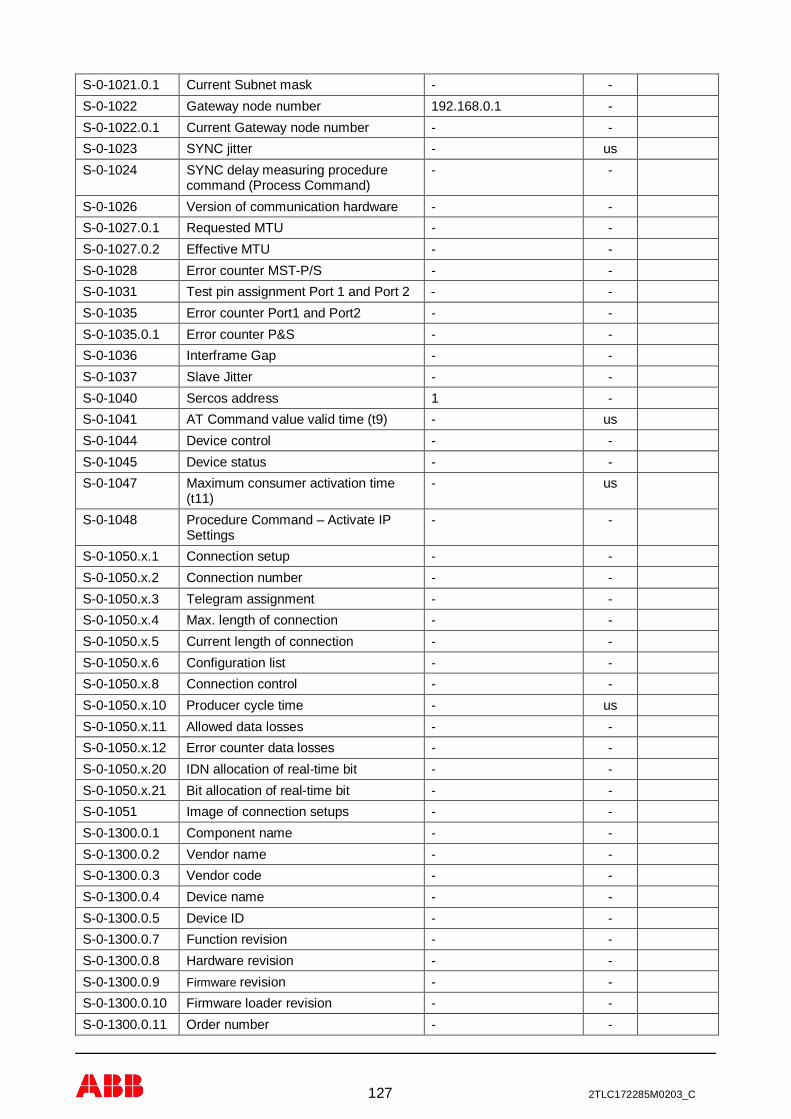
127 2TLC172285M0203_C
S-0-1021.0.1 Current Subnet mask - -S-0-1022 Gateway node number 192.168.0.1 -S-0-1022.0.1 Current Gateway node number - -S-0-1023 SYNC jitter - usS-0-1024 SYNC delay measuring procedure
command (Process Command)- -
S-0-1026 Version of communication hardware - -S-0-1027.0.1 Requested MTU - -S-0-1027.0.2 Effective MTU - -S-0-1028 Error counter MST-P/S - -S-0-1031 Test pin assignment Port 1 and Port 2 - -S-0-1035 Error counter Port1 and Port2 - -S-0-1035.0.1 Error counter P&S - -S-0-1036 Interframe Gap - -S-0-1037 Slave Jitter - -S-0-1040 Sercos address 1 -S-0-1041 AT Command value valid time (t9) - usS-0-1044 Device control - -S-0-1045 Device status - -S-0-1047 Maximum consumer activation time
(t11)- us
S-0-1048 Procedure Command – Activate IPSettings
- -
S-0-1050.x.1 Connection setup - -S-0-1050.x.2 Connection number - -S-0-1050.x.3 Telegram assignment - -S-0-1050.x.4 Max. length of connection - -S-0-1050.x.5 Current length of connection - -S-0-1050.x.6 Configuration list - -S-0-1050.x.8 Connection control - -S-0-1050.x.10 Producer cycle time - usS-0-1050.x.11 Allowed data losses - -S-0-1050.x.12 Error counter data losses - -S-0-1050.x.20 IDN allocation of real-time bit - -S-0-1050.x.21 Bit allocation of real-time bit - -S-0-1051 Image of connection setups - -S-0-1300.0.1 Component name - -S-0-1300.0.2 Vendor name - -S-0-1300.0.3 Vendor code - -S-0-1300.0.4 Device name - -S-0-1300.0.5 Device ID - -S-0-1300.0.7 Function revision - -S-0-1300.0.8 Hardware revision - -S-0-1300.0.9 Firmware revision - -S-0-1300.0.10 Firmware loader revision - -S-0-1300.0.11 Order number - -
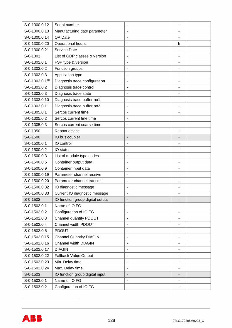
128 2TLC172285M0203_C
S-0-1300.0.12 Serial number - -S-0-1300.0.13 Manufacturing date parameter - -S-0-1300.0.14 QA Date - -S-0-1300.0.20 Operational hours. - hS-0-1300.0.21 Service Date - -S-0-1301 List of GDP classes & version - -S-0-1302.0.1 FSP type & version - -S-0-1302.0.2 Function groups - -S-0-1302.0.3 Application type - -S-0-1303.0.110 Diagnosis trace configuration - -S-0-1303.0.2 Diagnosis trace control - -S-0-1303.0.3 Diagnosis trace state - -S-0-1303.0.10 Diagnosis trace buffer no1 - -S-0-1303.0.11 Diagnosis trace buffer no2 - -S-0-1305.0.1 Sercos current time - -S-0-1305.0.2 Sercos current fine time -S-0-1305.0.3 Sercos current coarse time -S-0-1350 Reboot device - -S-0-1500 IO bus coupler - -S-0-1500.0.1 IO control - -S-0-1500.0.2 IO status - -S-0-1500.0.3 List of module type codes - -S-0-1500.0.5 Container output data - -S-0-1500.0.9 Container input data - -S-0-1500.0.19 Parameter channel receive - -S-0-1500.0.20 Parameter channel transmit - -S-0-1500.0.32 IO diagnostic message - -S-0-1500.0.33 Current IO diagnostic message - -S-0-1502 IO function group digital output - -S-0-1502.0.1 Name of IO FG - -S-0-1502.0.2 Configuration of IO FG - -S-0-1502.0.3 Channel quantity PDOUT - -S-0-1502.0.4 Channel width PDOUT - -S-0-1502.0.5 PDOUT - -S-0-1502.0.15 Channel Quantity DIAGIN - -S-0-1502.0.16 Channel width DIAGIN - -S-0-1502.0.17 DIAGIN - -S-0-1502.0.22 Fallback Value Output - -S-0-1502.0.23 Min. Delay time - -S-0-1502.0.24 Max. Delay time - -S-0-1503 IO function group digital input - -S-0-1503.0.1 Name of IO FG - -S-0-1503.0.2 Configuration of IO FG - -
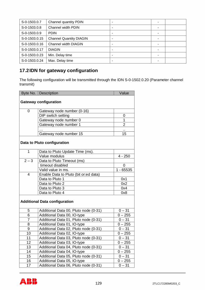
129 2TLC172285M0203_C
S-0-1503.0.7 Channel quantity PDIN - -S-0-1503.0.8 Channel width PDIN - -S-0-1503.0.9 PDIN - -S-0-1503.0.15 Channel Quantity DIAGIN - -S-0-1503.0.16 Channel width DIAGIN - -S-0-1503.0.17 DIAGIN - -S-0-1503.0.23 Min. Delay time - -S-0-1503.0.24 Max. Delay time - -
17.2 IDN for gateway configuration
The following configuration will be transmitted through the IDN S-0-1502.0.20 (Parameter channeltransmit)
Byte No. Description Value
Gateway configuration
0 Gateway node number (0-16)DIP switch setting 0Gateway node number 0 1Gateway node number 1 2… ..Gateway node number 15 15
Data to Pluto configuration
1 Data to Pluto Update Time (ms).Value modulus 4 - 250
2 – 3 Data to Pluto Timeout (ms) timeout disabled 0Valid value in ms. 1 - 65535
4 Enable Data to Pluto (bit or:ed data)Data to Pluto 1 0x1Data to Pluto 2 0x2Data to Pluto 3 0x4Data to Pluto 4 0x8
Additional Data configuration
5 Additional Data 00, Pluto node (0-31) 0 – 316 Additional Data 00, IO-type 0 – 2557 Additional Data 01, Pluto node (0-31) 0 – 318 Additional Data 01, IO-type 0 – 2559 Additional Data 02, Pluto node (0-31) 0 – 31
10 Additional Data 02, IO-type 0 – 25511 Additional Data 03, Pluto node (0-31) 0 – 3112 Additional Data 03, IO-type 0 – 25513 Additional Data 04, Pluto node (0-31) 0 – 3114 Additional Data 04, IO-type 0 – 25515 Additional Data 05, Pluto node (0-31) 0 – 3116 Additional Data 05, IO-type 0 – 25517 Additional Data 06, Pluto node (0-31) 0 – 31

130 2TLC172285M0203_C
Byte No. Description Value18 Additional Data 06, IO-type 0 – 25519 Additional Data 07, Pluto node (0-31) 0 – 3120 Additional Data 07, IO-type 0 – 25521 Additional Data 08, Pluto node (0-31) 0 – 3122 Additional Data 08, IO-type 0 – 25523 Additional Data 09, Pluto node (0-31) 0 – 3124 Additional Data 09, IO-type 0 – 25525 Additional Data 10, Pluto node (0-31) 0 – 3126 Additional Data 10, IO-type 0 – 25527 Additional Data 11, Pluto node (0-31) 0 – 3128 Additional Data 11, IO-type 0 – 25529 Additional Data 12, Pluto node (0-31) 0 – 3130 Additional Data 12, IO-type 0 – 25531 Additional Data 13, Pluto node (0-31) 0 – 3132 Additional Data 13, IO-type 0 – 25533 Additional Data 14, Pluto node (0-31) 0 – 3134 Additional Data 14, IO-type 0 – 25535 Additional Data 15, Pluto node (0-31) 0 – 3136 Additional Data 15, IO-type 0 – 25537 Additional Data 16, Pluto node (0-31) 0 – 3138 Additional Data 16, IO-type 0 – 25539 Additional Data 17, Pluto node (0-31) 0 – 3140 Additional Data 17, IO-type 0 – 25541 Additional Data 18, Pluto node (0-31) 0 – 3142 Additional Data 18, IO-type 0 – 25543 Additional Data 19, Pluto node (0-31) 0 – 3144 Additional Data 19, IO-type 0 – 25545 Additional Data 20, Pluto node (0-31) 0 – 3146 Additional Data 20, IO-type 0 – 25547 Additional Data 21, Pluto node (0-31) 0 – 3148 Additional Data 21, IO-type 0 – 25549 Additional Data 22, Pluto node (0-31) 0 – 3150 Additional Data 22, IO-type 0 – 25551 Additional Data 23, Pluto node (0-31) 0 – 3152 Additional Data 23, IO-type 0 – 25553 Additional Data 24, Pluto node (0-31) 0 – 3154 Additional Data 24, IO-type 0 – 25555 Additional Data 25, Pluto node (0-31) 0 – 3156 Additional Data 25, IO-type 0 – 25557 Additional Data 26, Pluto node (0-31) 0 – 3158 Additional Data 26, IO-type 0 – 25559 Additional Data 27, Pluto node (0-31) 0 – 3160 Additional Data 27, IO-type 0 – 25561 Additional Data 28, Pluto node (0-31) 0 – 3162 Additional Data 28, IO-type 0 – 25563 Additional Data 29, Pluto node (0-31) 0 – 3164 Additional Data 29, IO-type 0 – 25565 Additional Data 30, Pluto node (0-31) Not used66 Additional Data 30, IO-type Not used67 Additional Data 31, Pluto node (0-31) Not used68 Additional Data 31, IO-type Not used
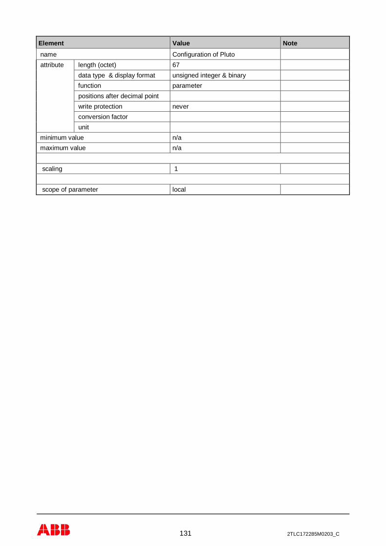
131 2TLC172285M0203_C
Element Value Note name Configuration of Pluto attribute length (octet) 67
data type & display format unsigned integer & binary function parameter positions after decimal point write protection never conversion factor unit
minimum value n/a maximum value n/a
scaling 1
scope of parameter local
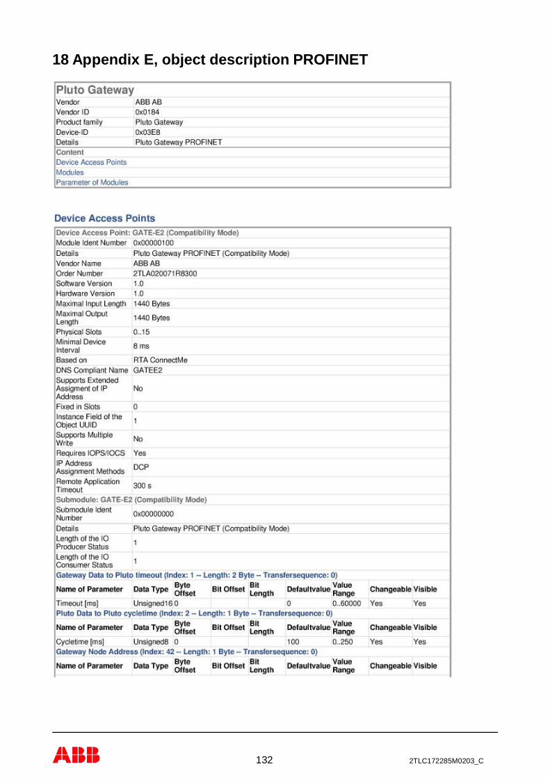
132 2TLC172285M0203_C
18 Appendix E, object description PROFINET
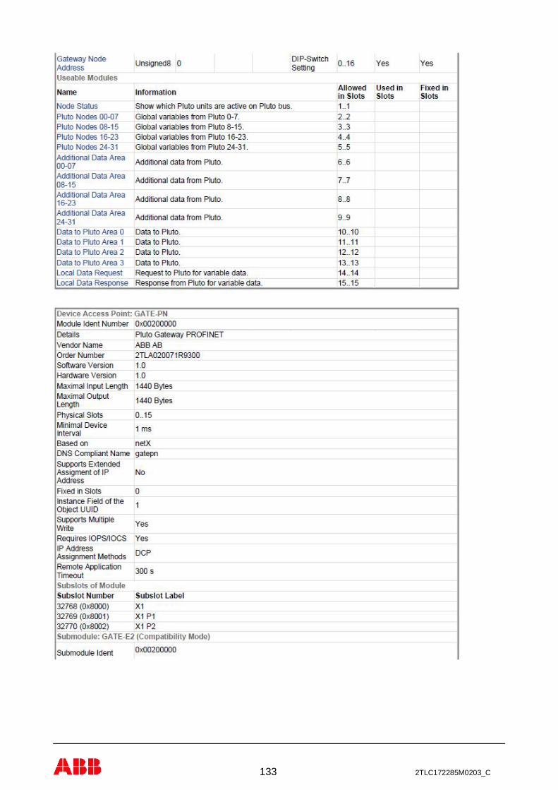
133 2TLC172285M0203_C

134 2TLC172285M0203_C

135 2TLC172285M0203_C

136 2TLC172285M0203_C

137 2TLC172285M0203_C

138 2TLC172285M0203_C

139 2TLC172285M0203_C

140 2TLC172285M0203_C

141 2TLC172285M0203_C
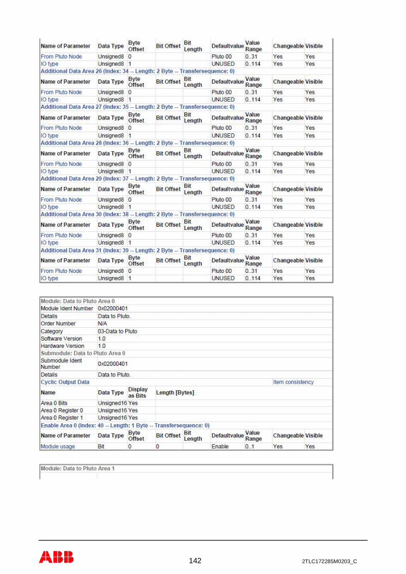
142 2TLC172285M0203_C
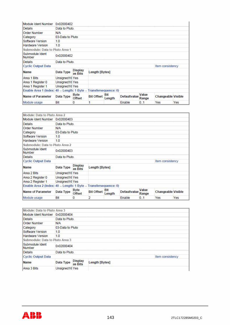
143 2TLC172285M0203_C
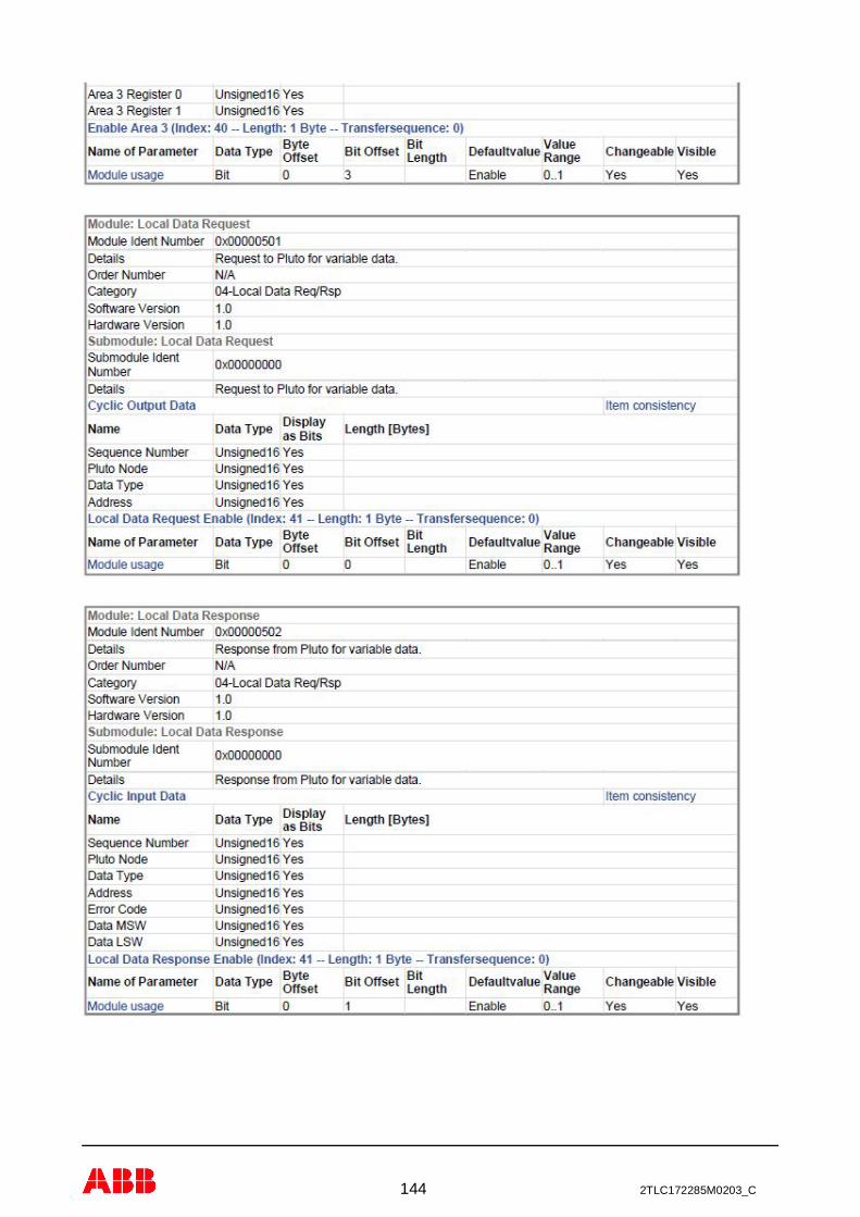
144 2TLC172285M0203_C

145 2TLC172285M0203_C

146 2TLC172285M0203_C

147 2TLC172285M0203_C

148 2TLC172285M0203_C
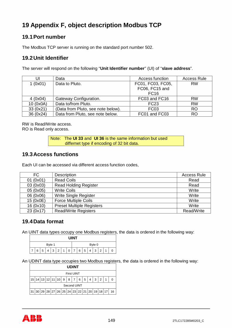
149 2TLC172285M0203_C
19 Appendix F, object description Modbus TCP
19.1 Port number
The Modbus TCP server is running on the standard port number 502.
19.2 Unit Identifier
The server will respond on the following “Unit Identifier number” (UI) of “slave address”.
UI Data Access function Access Rule1 (0x01) Data to Pluto. FC01, FC03, FC05,
FC06, FC15 andFC16
RW
4 (0x04) Gateway Configuration. FC03 and FC16 RW10 (0x0A) Data to/from Pluto. FC23 RW33 (0x21) (Data from Pluto, see note below). FC03 RO36 (0x24) Data from Pluto, see note below. FC01 and FC03 RO
RW is Read/Write access.RO is Read only access.
19.3 Access functions
Each UI can be accessed via different access function codes,
FC Description Access Rule01 (0x01) Read Coils Read03 (0x03) Read Holding Register Read05 (0x05) Write Coils Write06 (0x06) Write Single Register Write15 (0x0E) Force Multiple Coils Write16 (0x10) Preset Multiple Registers Write23 (0x17) Read/Write Registers Read/Write
19.4 Data format
An UINT data types occupy one Modbus registers, the data is ordered in the following way:UINT
Byte 1 Byte 0
7 6 5 4 3 2 1 0 7 6 5 4 3 2 1 0
An UDINT data type occupies two Modbus registers, the data is ordered in the following way:UDINT
First UINT
15 14 13 12 11 10 9 8 7 6 5 4 3 2 1 0
Second UINT
31 30 29 28 27 26 25 24 23 22 21 20 19 18 17 16
Note: The UI 33 and UI 36 is the same information but useddiffernet type if encoding of 32 bit data.
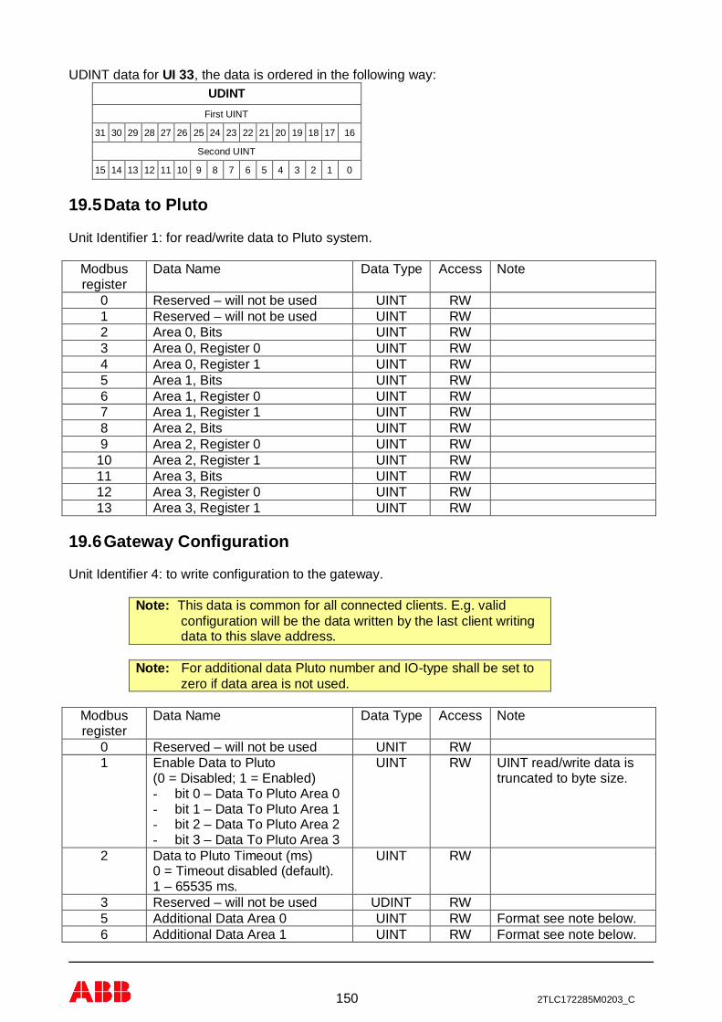
150 2TLC172285M0203_C
UDINT data for UI 33, the data is ordered in the following way:UDINT
First UINT
31 30 29 28 27 26 25 24 23 22 21 20 19 18 17 16
Second UINT
15 14 13 12 11 10 9 8 7 6 5 4 3 2 1 0
19.5 Data to Pluto
Unit Identifier 1: for read/write data to Pluto system.
Modbusregister
Data Name Data Type Access Note
0 Reserved – will not be used UINT RW1 Reserved – will not be used UINT RW2 Area 0, Bits UINT RW3 Area 0, Register 0 UINT RW4 Area 0, Register 1 UINT RW5 Area 1, Bits UINT RW6 Area 1, Register 0 UINT RW7 Area 1, Register 1 UINT RW8 Area 2, Bits UINT RW9 Area 2, Register 0 UINT RW
10 Area 2, Register 1 UINT RW11 Area 3, Bits UINT RW12 Area 3, Register 0 UINT RW13 Area 3, Register 1 UINT RW
19.6 Gateway Configuration
Unit Identifier 4: to write configuration to the gateway.
Note: This data is common for all connected clients. E.g. validconfiguration will be the data written by the last client writingdata to this slave address.
Note: For additional data Pluto number and IO-type shall be set tozero if data area is not used.
Modbusregister
Data Name Data Type Access Note
0 Reserved – will not be used UNIT RW1 Enable Data to Pluto
(0 = Disabled; 1 = Enabled)- bit 0 – Data To Pluto Area 0- bit 1 – Data To Pluto Area 1- bit 2 – Data To Pluto Area 2- bit 3 – Data To Pluto Area 3
UINT RW UINT read/write data istruncated to byte size.
2 Data to Pluto Timeout (ms)0 = Timeout disabled (default).1 – 65535 ms.
UINT RW
3 Reserved – will not be used UDINT RW5 Additional Data Area 0 UINT RW Format see note below.6 Additional Data Area 1 UINT RW Format see note below.

151 2TLC172285M0203_C
Modbusregister
Data Name Data Type Access Note
7 Additional Data Area 2 UINT RW Format see note below.8 Additional Data Area 3 UINT RW Format see note below.9 Additional Data Area 4 UINT RW Format see note below.
10 Additional Data Area 5 UINT RW Format see note below.11 Additional Data Area 6 UINT RW Format see note below.12 Additional Data Area 7 UINT RW Format see note below.13 Additional Data Area 8 UINT RW Format see note below.14 Additional Data Area 9 UINT RW Format see note below.15 Additional Data Area 10 UINT RW Format see note below.16 Additional Data Area 11 UINT RW Format see note below.17 Additional Data Area 12 UINT RW Format see note below.18 Additional Data Area 13 UINT RW Format see note below.19 Additional Data Area 14 UINT RW Format see note below.20 Additional Data Area 15 UINT RW Format see note below.21 Additional Data Area 16 UINT RW Format see note below.22 Additional Data Area 17 UINT RW Format see note below.23 Additional Data Area 18 UINT RW Format see note below.24 Additional Data Area 19 UINT RW Format see note below.25 Additional Data Area 20 UINT RW Format see note below.26 Additional Data Area 21 UINT RW Format see note below.27 Additional Data Area 22 UINT RW Format see note below.28 Additional Data Area 23 UINT RW Format see note below.29 Additional Data Area 24 UINT RW Format see note below.30 Additional Data Area 25 UINT RW Format see note below.31 Additional Data Area 26 UINT RW Format see note below.32 Additional Data Area 27 UINT RW Format see note below.33 Additional Data Area 28 UINT RW Format see note below.34 Additional Data Area 29 UINT RW Format see note below.35 Additional Data Area 30 UINT RW Format see note below.36 Additional Data Area 31 UINT RW Format see note below.37 Data to Pluto Cycle time (ms)
0 – 255 ms, default 100 msUINT RW UINT read/write data is
truncated to byte size.38 Reserved – will not be used UINT RW39 Reserved – will not be used UINT RW40 Reserved – will not be used UINT RW41 Gateway Node number (0-16)
0 = Read from DIP switch1 = Gateway node number 02 = Gateway node number 1…16 = Gateway node number 15For more see chapter 6.1.4.1.
UINT RW UINT read/write data istruncated to byte size.
The UINT configuration data is allocated as following:UINT
Byte 1 (high byte) Byte 0 (low byte)
Pluto node number, range 0 – 31. IO-typ, range 0 – 255.

152 2TLC172285M0203_C
19.7 Data to/from Pluto
Unit Identifier 10: Read global data from Pluto and write data to Pluto
Modbusregister
Data Name Data Type Access Note
0 Pluto node status UDINT RO2 Global data Pluto 0 UDINT RO4 Global data Pluto 1 UDINT RO6 Global data Pluto 2 UDINT RO8 Global data Pluto 3 UDINT RO
10 Global data Pluto 4 UDINT RO12 Global data Pluto 5 UDINT RO14 Global data Pluto 6 UDINT RO16 Global data Pluto 7 UDINT RO18 Global data Pluto 8 UDINT RO20 Global data Pluto 9 UDINT RO22 Global data Pluto 10 UDINT RO24 Global data Pluto 11 UDINT RO26 Global data Pluto 12 UDINT RO28 Global data Pluto 13 UDINT RO30 Global data Pluto 14 UDINT RO32 Global data Pluto 15 UDINT RO34 Global data Pluto 16 UDINT RO36 Global data Pluto 17 UDINT RO38 Global data Pluto 18 UDINT RO40 Global data Pluto 19 UDINT RO42 Global data Pluto 20 UDINT RO44 Global data Pluto 21 UDINT RO46 Global data Pluto 22 UDINT RO48 Global data Pluto 23 UDINT RO50 Global data Pluto 24 UDINT RO52 Global data Pluto 25 UDINT RO54 Global data Pluto 26 UDINT RO56 Global data Pluto 27 UDINT RO58 Global data Pluto 28 UDINT RO60 Global data Pluto 29 UDINT RO62 Global data Pluto 30 UDINT RO64 Global data Pluto 31 UDINT RO66 Additional data 0 UDINT RO68 Additional data 1 UDINT RO70 Additional data 2 UDINT RO72 Additional data 3 UDINT RO74 Additional data 4 UDINT RO76 Additional data 5 UDINT RO78 Additional data 6 UDINT RO80 Additional data 7 UDINT RO82 Additional data 8 UDINT RO84 Additional data 9 UDINT RO86 Additional data 10 UDINT RO88 Additional data 11 UDINT RO90 Additional data 12 UDINT RO92 Additional data 13 UDINT RO94 Additional data 14 UDINT RO96 Additional data 15 UDINT RO

153 2TLC172285M0203_C
Modbusregister
Data Name Data Type Access Note
98 Additional data 16 UDINT RO100 Additional data 17 UDINT RO102 Additional data 18 UDINT RO104 Additional data 19 UDINT RO106 Additional data 20 UDINT RO108 Additional data 21 UDINT RO110 Additional data 22 UDINT RO112 Additional data 23 UDINT RO114 Additional data 24 UDINT RO116 Additional data 25 UDINT RO118 Additional data 26 UDINT RO120 Additional data 27 UDINT RO122 Additional data 28 UDINT RO124 Additional data 29 UDINT RO126 Additional data 30 UDINT RO128 Additional data 31 UDINT RO
130-198 Not used UDINT Not mapped200 Area 0, Bits UINT RW201 Area 0, Register 0 UINT RW202 Area 0, Register 1 UINT RW203 Area 1, Bits UINT RW204 Area 1, Register 0 UINT RW205 Area 1, Register 1 UINT RW206 Area 2, Bits UINT RW207 Area 2, Register 0 UINT RW208 Area 2, Register 1 UINT RW209 Area 3, Bits UINT RW210 Area 3, Register 0 UINT RW211 Area 3, Register 1 UINT RW
19.8 Data from Pluto
Unit Identifier 33 and 36: for read Pluto node status, global data from each Pluto and alsoadditional data from the Pluto system.
Note: Note that UI 33 and UI36 has different layout of the UDINT(see 19.4). The UI33 is implemented for compatibility with theGATE-E2 and new usage shall use the UI36 with thestandard format of UDINT for Modbus TCP (see 19.2).
Note: Only 100 words can be read in one request!
If more data is needed divide them in two or more request with selected start/end address in therequest. For example a request with start 1 and end 66 will give node status and Pluto global data.A request with start 67 and end 130 will give additional data.
Modbusregister
Data Name Data Type Access Note
0 Reserved – will not be used UINT RO1 Pluto node status UDINT RO3 Global data Pluto 0 UDINT RO

154 2TLC172285M0203_C
Modbusregister
Data Name Data Type Access Note
5 Global data Pluto 1 UDINT RO7 Global data Pluto 2 UDINT RO9 Global data Pluto 3 UDINT RO
11 Global data Pluto 4 UDINT RO13 Global data Pluto 5 UDINT RO15 Global data Pluto 6 UDINT RO17 Global data Pluto 7 UDINT RO19 Global data Pluto 8 UDINT RO21 Global data Pluto 9 UDINT RO23 Global data Pluto 10 UDINT RO25 Global data Pluto 11 UDINT RO27 Global data Pluto 12 UDINT RO29 Global data Pluto 13 UDINT RO31 Global data Pluto 14 UDINT RO33 Global data Pluto 15 UDINT RO35 Global data Pluto 16 UDINT RO37 Global data Pluto 17 UDINT RO39 Global data Pluto 18 UDINT RO41 Global data Pluto 19 UDINT RO43 Global data Pluto 20 UDINT RO45 Global data Pluto 21 UDINT RO47 Global data Pluto 22 UDINT RO49 Global data Pluto 23 UDINT RO51 Global data Pluto 24 UDINT RO53 Global data Pluto 25 UDINT RO55 Global data Pluto 26 UDINT RO57 Global data Pluto 27 UDINT RO59 Global data Pluto 28 UDINT RO61 Global data Pluto 29 UDINT RO63 Global data Pluto 30 UDINT RO65 Global data Pluto 31 UDINT RO67 Additional data 0 UDINT RO69 Additional data 1 UDINT RO71 Additional data 2 UDINT RO73 Additional data 3 UDINT RO75 Additional data 4 UDINT RO77 Additional data 5 UDINT RO79 Additional data 6 UDINT RO81 Additional data 7 UDINT RO83 Additional data 8 UDINT RO85 Additional data 9 UDINT RO87 Additional data 10 UDINT RO89 Additional data 11 UDINT RO91 Additional data 12 UDINT RO93 Additional data 13 UDINT RO95 Additional data 14 UDINT RO97 Additional data 15 UDINT RO99 Additional data 16 UDINT RO
101 Additional data 17 UDINT RO103 Additional data 18 UDINT RO105 Additional data 19 UDINT RO107 Additional data 20 UDINT RO109 Additional data 21 UDINT RO

155 2TLC172285M0203_C
Modbusregister
Data Name Data Type Access Note
111 Additional data 22 UDINT RO113 Additional data 23 UDINT RO115 Additional data 24 UDINT RO117 Additional data 25 UDINT RO119 Additional data 26 UDINT RO121 Additional data 27 UDINT RO123 Additional data 28 UDINT RO125 Additional data 29 UDINT RO127 Additional data 30 UDINT RO129 Additional data 31 UDINT RO

156 2TLC172285M0203_C
Contact informationAustraliaABB Australia Pty LimitedLow Voltage ProductsTel: +61 (0)1300 660 299Fax: +61 (0)1300 853 138Mob: +61 (0)401 714 392E-mail: [email protected]: www.abbaustralia.com.au
AustriaABB AB, Jokab SafetyTel: +43 (0)1 601 09-6204Fax: +43 (0)1 601 09-8600E-mail: [email protected]: www.abb.at
BelgiumABB N.V.Tel: +32 27186884Fax: +32 27186831E-mail: [email protected]
BrazilABB LtdaProdutos de Baixa TensãoABB Atende: 0800 014 9111Fax: +55 11 3688-9977Web: www.abb.com.br
CanadaABB Inc.Tel: +1 514 420 3100 Ext 3269Fax: +1 514 420 3137Mobile: +1 514 247 4025E-mail: [email protected]: www.abb.com
ChinaABB (China) LimitedTel: 86-21-23287948Telefax: 86-21-23288558Mobile: 86-186 2182 1159E-mail: [email protected]
Czech RepublicABB AB, Jokab SafetyTel: +420 543 145 482Fax: +420 543 243 489E-mail: [email protected]: www.abb.cz
DenmarkJOKAB SAFETY DK A/STel: +45 44 34 14 54Fax: +45 44 99 14 54E-mail: [email protected]: www.jokabsafety.dk
ABB A/STel: +45 4450 4450Fax: +45 4359 5920E-mail: [email protected]: www.abb.dk
FinlandABB OyWeb: www.abb.fi
FranceABB FranceDivision Produits Basse TensionTel: 0825 38 63 55Fax: 0825 87 09 26Web: www.abb.com
GermanyABB STOTZ-KONTAKT GmbHTel: +49 (0) 7424-95865-0Fax: +49 (0) 7424-95865-99E-mail: [email protected]: www.jokabsafety.com
GreeceΑΒΒ SATel: +30 210.28.91.900Fax: +30 210.28.91.999E-mail: [email protected]
[email protected]: www.abb.com
IrelandABB Ltd.Tel +353 1 4057 381Fax: +353 1 4057 312Mobile: +353 86 2532891E-mail: [email protected]
IsraelABB Technologies Ltd.Tel: +972 4 851-9204Mobile: +972 52 485-6284E-mail: [email protected]: www.abb.co.il
ItalyABB S.p.A.Tel. +39 02 2414.1Fax +39 02 2414.2330Web: www.abb.it
KoreaABB KOREALow-voltage ProductTel: +82 2 528 3177Fax: +82 2 528 2350Web: www.jokabsafety.co.kr
MalaysiaABB MalaysiaTel: +60356284888 4282E-mail: [email protected]
NetherlandsABB b.v.Tel:+31 (0) 10 - 4078 947Fax: +31 (0) 10 – 4078 090E-mail: [email protected]: www.abb.nl
NorwayABB ASTel: +47 03500Fax: +47 32858021Mobile: +47 40918930E-mail: [email protected]: www.abb.no
PolandABB Sp. z.o.oTel: +48 728 401 403Fax: 22 220 22 23E-mail: [email protected],
[email protected]: www.abb.pl
PortugalAsea Brown Boveri S.A.Low Voltage Products - Baixa TensãoTel: +35 214 256 000Fax: +35 214 256 390Web: www.abb.es
SloveniaABB d.o.o.Tel: +386 1 2445 455Fax: +386 1 2445 490E-mail: [email protected]
SpainAsea Brown Boveri S.A.Tel: +34 93 4842121Fax: +34 93 484 21 90Web: www.abb.es
South AfricaABBTel: +27 10 202 5906Fax: +27 11 579 8203Mobile: +27 82 500 7990E-mail: [email protected]
SwedenABB AB, Jokab SafetyVarlabergsvägen 11SE-434 39 KungsbackaTel: +46 21 32 50 00Fax: +46 40 67 15 601E-mail: [email protected]: www.abb.com/jokabsafety
SwitzerlandABB Schweiz AGIndustrie- und GebäudeautomationTel: +41 58 586 00 00Fax: +41 58 586 06 01E-mail: [email protected]: www.abb.ch
TurkeyABB Elektrik Sanayi A.ŞTel: 0216 528 22 00Fax: 0216 365 29 44
United KingdomABB Ltd/JOKAB SAFETY UKTel: +44 (0) 2476 368500Fax: +44 (0) 2476 368401E-mail: [email protected]: www.jokabsafety.com
USA/MexicoABB Jokab Safety North AmericaTel: +1 519 735 1055Fax: +1 519 7351299E-mail: [email protected]: www.jokabsafetyna.com