plumbing systems engineered plastic (ep) valved...
TRANSCRIPT

InstallatIon GuIde
PlumbINg SySTemS
enGIneered PlastIc (eP) valved manIfolds
uponor, Inc.5925 148th Street Westapple Valley, mN 55124 uSa Tel: (800) 321-4739Fax: (952) 891-2008Web: www.uponor-usa.com
Uponor Engineered Plastic (EP) Valved Manifolds Installation Guide
eP_m
fld_I
gH
b_10
-07,
Cop
yrig
ht ©
2007
upo
nor,
Inc.
Prin
ted
in t
he u
nite
d St
ates
uponor engineered Plastic (eP) valved manifolds Installation Guide Published by uponor, Inc. 5925 148th Street West apple Valley, mN 55124 uSa (800) 321-4739 www.uponor-usa.com
© 2007 uponor, Inc. all Rights Reserved.
Second edition, October 2007 First Printing October 2002 Printed in the united States of america
iengineered Plastic (eP) valved manifolds Installation Guidewww.uponor-usa.com
Table of Contents
section 1 – the engineered Plastic (eP) clean Water management system
eP Valved manifold System Standards, Ratings and Certifications . . . . 1
section 2 – Important Product Information . . . . . . . . . . . 3
section 3 – eP valved manifold sizing Guidelinesgeneral guidelines . . . . . . . . . . . . . . . . . . . . . . . . . . . . . . . . . . . . . . . . 5engineered Parallel Water Distribution System Design Information — 3⁄8" Tubing . . . . . . . . . . . . . . . . . . . . . . . . . . . . . 6
section 4 – eP valved manifold InstallationTools Required . . . . . . . . . . . . . . . . . . . . . . . . . . . . . . . . . . . . . . . . . . . 7materials Required . . . . . . . . . . . . . . . . . . . . . . . . . . . . . . . . . . . . . . . . 7eP Valved manifold assembly. . . . . . . . . . . . . . . . . . . . . . . . . . . . . . . . 7eP Valved manifold Placement . . . . . . . . . . . . . . . . . . . . . . . . . . . . . . . 9 guidelines. . . . . . . . . . . . . . . . . . . . . . . . . . . . . . . . . . . . . . . . . . . . . 9 Tips for mounting eP Valved manifolds . . . . . . . . . . . . . . . . . . . . . . 9 using the Drill guide . . . . . . . . . . . . . . . . . . . . . . . . . . . . . . . . . . . 11 Connecting Wirsbo aQuaPeX Tubing to the eP Valved manifold . 11Filling and Testing the eP Valved manifold System . . . . . . . . . . . . . . 13 System Test . . . . . . . . . . . . . . . . . . . . . . . . . . . . . . . . . . . . . . . . . . 13 Filling the System . . . . . . . . . . . . . . . . . . . . . . . . . . . . . . . . . . . . . . 13System Disinfection . . . . . . . . . . . . . . . . . . . . . . . . . . . . . . . . . . . . . . 13eP Valve Replacement . . . . . . . . . . . . . . . . . . . . . . . . . . . . . . . . . . . . 14
section 5 – ProPeX® fitting systemmaking ProPeX Connections . . . . . . . . . . . . . . . . . . . . . . . . . . . . . . . 15Important Tips for a Proper ProPeX Connection. . . . . . . . . . . . . . . . . 17making 3⁄8" ProPeX Connections . . . . . . . . . . . . . . . . . . . . . . . . . . . . . 18Important Tips for a Proper 3⁄8" ProPeX Connection . . . . . . . . . . . . . . 18Disconnecting a ProPeX brass Fitting. . . . . . . . . . . . . . . . . . . . . . . . . 18Troubleshooting ProPeX Connections . . . . . . . . . . . . . . . . . . . . . . . . 19 For Fittings That Will Not Seal . . . . . . . . . . . . . . . . . . . . . . . . . . . . 19 If expansion is Difficult. . . . . . . . . . . . . . . . . . . . . . . . . . . . . . . . . . 19 If the expansion Head Slips out of the Tubing When making expansion . . . . . . . . . . . . . . . . . . . . . . . . . . . . . . 19 If the ProPeX Ring Slides Down the Tubing During expansion . . . 20 If more Than the Recommended Number of expansions are Needed to make a Connection. . . . . . . . . . . . . . . . . . . . . . . 20(Continued on Page ii)
section 1
The Engineered Plastic (EP) Clean Water Management System
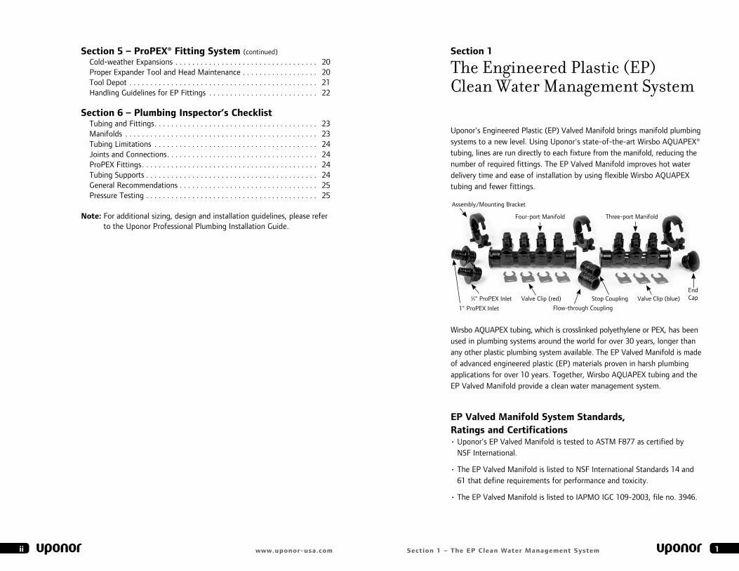
uponor's engineered Plastic (eP) Valved manifold brings manifold plumbing systems to a new level. using uponor's state-of-the-art Wirsbo aQuaPeX® tubing, lines are run directly to each fixture from the manifold, reducing the number of required fittings. The eP Valved manifold improves hot water delivery time and ease of installation by using flexible Wirsbo aQuaPeX tubing and fewer fittings.
Wirsbo aQuaPeX tubing, which is crosslinked polyethylene or PeX, has been used in plumbing systems around the world for over 30 years, longer than any other plastic plumbing system available. The eP Valved manifold is made of advanced engineered plastic (eP) materials proven in harsh plumbing applications for over 10 years. Together, Wirsbo aQuaPeX tubing and the eP Valved manifold provide a clean water management system.
eP valved manifold system standards, ratings and certifications• uponor's eP Valved manifold is tested to aSTm F877 as certified by
NSF International.
• The eP Valved manifold is listed to NSF International Standards 14 and 61 that define requirements for performance and toxicity.
• The eP Valved manifold is listed to IaPmO IgC 109-2003, file no. 3946.
1ii www.uponor-usa.com section 1 – the eP clean Water management system
Four-port manifold Three-port manifold
end CapValve Clip (red)
Flow-through Coupling
3⁄4" ProPeX Inlet
1" ProPeX Inlet
Stop Coupling
assembly/mounting bracket
Valve Clip (blue)
section 5 – ProPeX® fitting system (continued)Cold-weather expansions . . . . . . . . . . . . . . . . . . . . . . . . . . . . . . . . . . 20Proper expander Tool and Head maintenance . . . . . . . . . . . . . . . . . . 20Tool Depot . . . . . . . . . . . . . . . . . . . . . . . . . . . . . . . . . . . . . . . . . . . . . 21Handling guidelines for eP Fittings . . . . . . . . . . . . . . . . . . . . . . . . . . 22
section 6 – Plumbing Inspector’s checklistTubing and Fittings. . . . . . . . . . . . . . . . . . . . . . . . . . . . . . . . . . . . . . . 23manifolds . . . . . . . . . . . . . . . . . . . . . . . . . . . . . . . . . . . . . . . . . . . . . . 23Tubing limitations . . . . . . . . . . . . . . . . . . . . . . . . . . . . . . . . . . . . . . . 24Joints and Connections. . . . . . . . . . . . . . . . . . . . . . . . . . . . . . . . . . . . 24ProPeX Fittings. . . . . . . . . . . . . . . . . . . . . . . . . . . . . . . . . . . . . . . . . . 24Tubing Supports . . . . . . . . . . . . . . . . . . . . . . . . . . . . . . . . . . . . . . . . . 24general Recommendations . . . . . . . . . . . . . . . . . . . . . . . . . . . . . . . . . 25Pressure Testing . . . . . . . . . . . . . . . . . . . . . . . . . . . . . . . . . . . . . . . . . 25
note: For additional sizing, design and installation guidelines, please refer to the uponor Professional Plumbing Installation guide.
section 2
Important Product Information
failure to follow the instructions and installation guidelines in this manual can result in the failure of the uponor eP valved manifold clean Water management system.
• eP Valved manifold threaded outlets seal with a gasket and do not require joint compound or polytetrafluoroethylene (PTFe) tape.
• Do not overtighten connections by using tools. Tighten swivel nuts by hand until snug, plus one-quarter to one-half turn.
• Do not subject the eP Valved manifold to impact.
• Distribution lines should exit the eP Valved manifold in straight lines perpendicular to the length of the eP Valved manifold.
• Supply lines should enter or exit the eP Valved manifold in a straight line parallel to the length of the eP Valved manifold.
• Do not expose the PeX tubing or the eP Valved manifold to open flame.
• Do not allow solder, flux, solvents or urethane foams to come into contact with the eP Valved manifolds, as immediate damage may result.
• Do not assemble or disassemble the eP Valved manifold while pressurized. be sure that the water supply is turned off and that pressure has been relieved from the system.
• Do not conceal the eP Valved manifold behind permanent walls, floors or ceilings.
• Keep the Valve-turning Tool in an accessible location near the eP Valved manifold.
• Hang or fasten the manifold kit supplied with the eP Valved manifold nearby for future reference.
• always inform the homeowner where the eP Valved manifold is located if fixture stops are omitted.
• Do not spray on or allow organic chemicals, strong acids or strong bases to come into contact with eP Valved manifolds.
• Do not use petroleum or solvent-based paints on eP Valved manifolds.
• Do not allow rodents, insects or other pests to come into contact with eP Valved manifolds.
32 section 2 – Important Product Informationwww.uponor-usa.com
section 3
EP Valved Manifold Sizing Guidelines
The general sizing information shown below is appropriate for many eP Valved manifold installations. For additional sizing information, refer to the uponor Professional Plumbing Installation guide. Please consult local code for the proper sizing information.
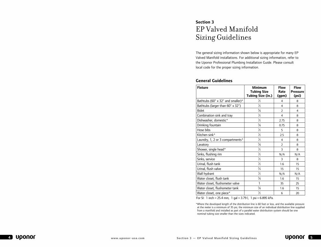
General Guidelines
* Where the developed length of the distribution line is 60 feet or less, and the available pressure at the meter is a minimum of 35 psi, the minimum size of an individual distribution line supplied from a manifold and installed as part of a parallel water distribution system should be one nominal tubing size smaller than the sizes indicated.
5section 3 — eP valved manifold sizing Guidelines4 www.uponor-usa.com
fixture minimum flow flow tubing size rate Pressure tubing size (in.) (gpm) (psi)
bathtubs (60" x 32" and smaller)* 1⁄2 4 8
bathtubs (larger than 60" x 32") 1⁄2 4 8
bidet 3⁄8 2 4
Combination sink and tray 1⁄2 4 8
Dishwasher, domestic* 1⁄2 2.75 8
Drinking fountain 3⁄8 0.75 8
Hose bibs 1⁄2 5 8
Kitchen sink* 1⁄2 2.5 8
laundry, 1, 2 or 3 compartments* 1⁄2 4 8
lavatory 3⁄8 2 8
Shower, single head* 1⁄2 3 8
Sinks, flushing rim 1⁄2 N/a N/a
Sinks, service 1⁄2 3 8
urinal, flush tank 1⁄2 1.6 15
urinal, flush valve 3⁄4 15 15
Wall hydrant 1⁄2 N/a N/a
Water closet, flush tank 3⁄8 1.6 15
Water closet, flushometer valve 1 35 25
Water closet, flushometer tank 3⁄8 1.6 15
Wat er closet, one piece* 1⁄2 6 20
For SI: 1 inch = 25.4 mm, 1 gal = 3.79 l, 1 psi = 6.895 kPa.
section 4
EP Valved Manifold Installation
before you begin, gather appropriate tools and materials.
tools required• Screw gun or electric drill
• ProPeX® expander Tool (Q6295075, Q6301000 or Q6261500)
• ProPeX expander Tool Heads
• Tube Cutter (e6081125 or e6081128)
• 3⁄4" and 11⁄4" wood drill bits
materials required• 1" wood screws (for valved manifold mounting)
• 1⁄2" or 3⁄4" plywood (only required when mounting between studs)
• Wirsbo aQuaPeX Tubing
• eP Valved manifold Kit (includes Valve-turning Tool and hot/cold labels)
• ProPeX Swivel adapters ( 1⁄2" or 3⁄8" for 1⁄2 " NPSm-threaded outlets only)
• Tube uncoiler (recommended)
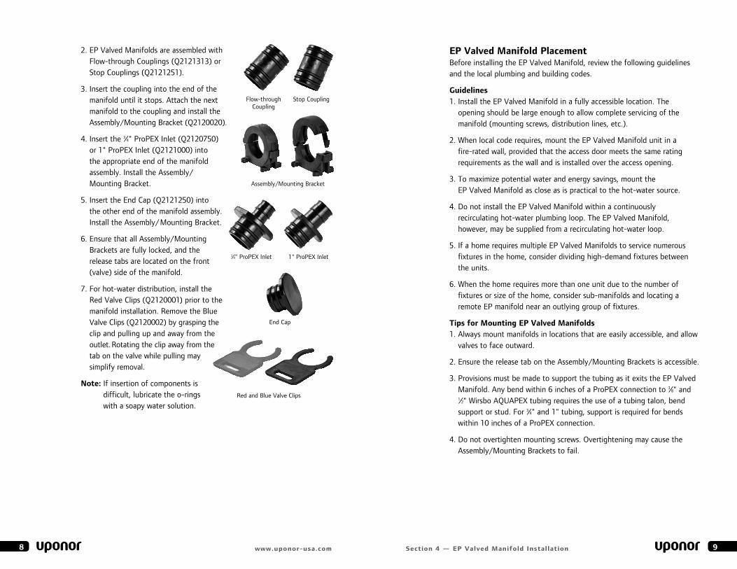
eP valved manifold assembly
The eP Valved manifold can either be assembled prior to or while it is being mounted.
1. Determine the total number of outlets required for both the hot and cold manifold assemblies and the appropriate inlet/end cap arrangement.
7section 4 — eP valved manifold Installation
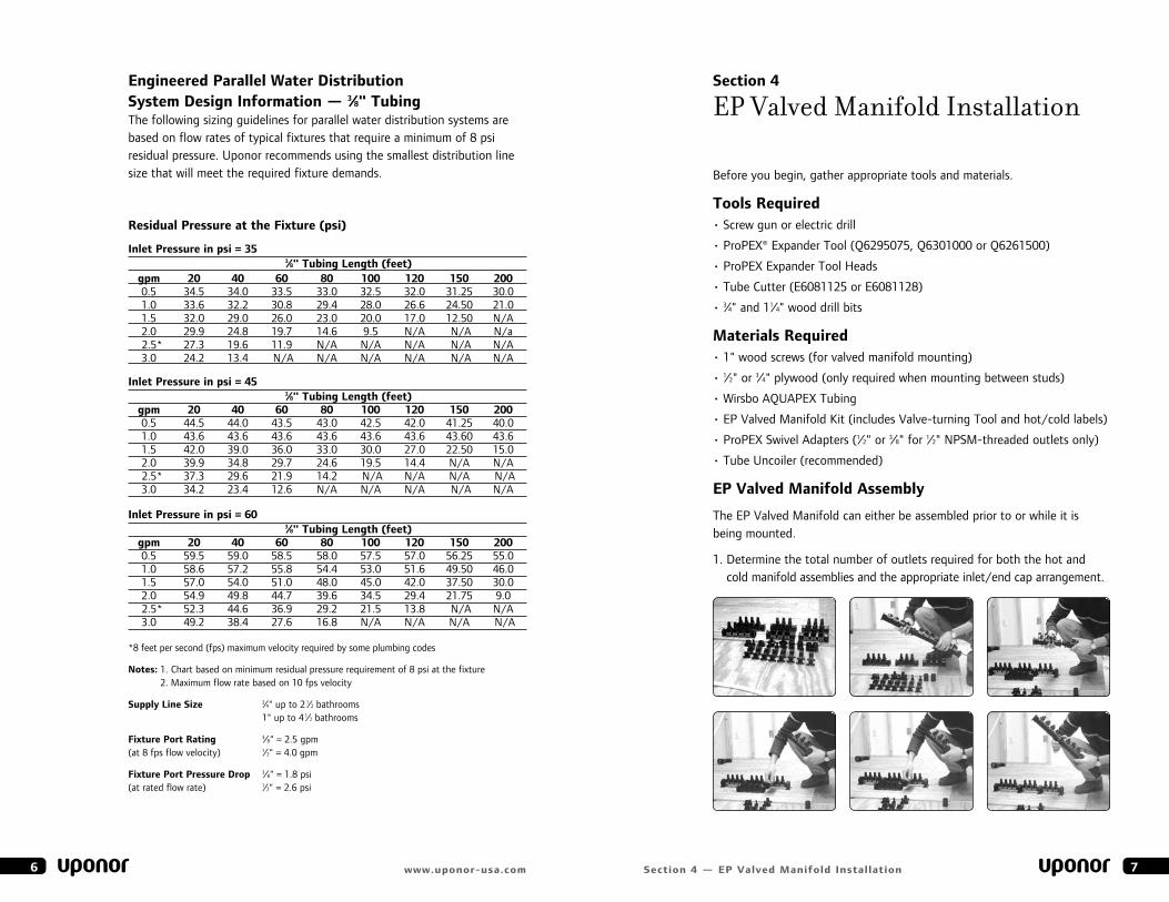
engineered Parallel Water distribution system design Information — 3⁄8" tubingThe following sizing guidelines for parallel water distribution systems are based on flow rates of typical fixtures that require a minimum of 8 psi residual pressure. uponor recommends using the smallest distribution line size that will meet the required fixture demands.
residual Pressure at the fixture (psi)
Inlet Pressure in psi = 35 3⁄8" tubing length (feet) gpm 20 40 60 80 100 120 150 200 0.5 34.5 34.0 33.5 33.0 32.5 32.0 31.25 30.0 1.0 33.6 32.2 30.8 29.4 28.0 26.6 24.50 21.0 1.5 32.0 29.0 26.0 23.0 20.0 17.0 12.50 N/a 2.0 29.9 24.8 19.7 14.6 9.5 N/a N/a N/a 2.5* 27.3 19.6 11.9 N/a N/a N/a N/a N/a 3.0 24.2 13.4 N/a N/a N/a N/a N/a N/a Inlet Pressure in psi = 45 3⁄8" tubing length (feet) gpm 20 40 60 80 100 120 150 200 0.5 44.5 44.0 43.5 43.0 42.5 42.0 41.25 40.0 1.0 43.6 43.6 43.6 43.6 43.6 43.6 43.60 43.6 1.5 42.0 39.0 36.0 33.0 30.0 27.0 22.50 15.0 2.0 39.9 34.8 29.7 24.6 19.5 14.4 N/a N/a 2.5* 37.3 29.6 21.9 14.2 N/a N/a N/a N/a 3.0 34.2 23.4 12.6 N/a N/a N/a N/a N/a Inlet Pressure in psi = 60 3⁄8" tubing length (feet) gpm 20 40 60 80 100 120 150 200 0.5 59.5 59.0 58.5 58.0 57.5 57.0 56.25 55.0 1.0 58.6 57.2 55.8 54.4 53.0 51.6 49.50 46.0 1.5 57.0 54.0 51.0 48.0 45.0 42.0 37.50 30.0 2.0 54.9 49.8 44.7 39.6 34.5 29.4 21.75 9.0 2.5* 52.3 44.6 36.9 29.2 21.5 13.8 N/a N/a 3.0 49.2 38.4 27.6 16.8 N/a N/a N/a N/a
* 8 feet per second (fps) maximum velocity required by some plumbing codes
notes: 1. Chart based on minimum residual pressure requirement of 8 psi at the fixture 2. maximum flow rate based on 10 fps velocity
supply line size 3⁄4" up to 2 1⁄2 bathrooms 1" up to 4 1⁄2 bathrooms
fixture Port rating 3⁄8" = 2.5 gpm (at 8 fps flow velocity) 1⁄2" = 4.0 gpm
fixture Port Pressure drop 3⁄8" = 1.8 psi (at rated flow rate) 1⁄2" = 2.6 psi
6 www.uponor-usa.com
eP valved manifold Placement before installing the eP Valved manifold, review the following guidelines and the local plumbing and building codes.
Guidelines1. Install the eP Valved manifold in a fully accessible location. The
opening should be large enough to allow complete servicing of the manifold (mounting screws, distribution lines, etc.).
2. When local code requires, mount the eP Valved manifold unit in a fire-rated wall, provided that the access door meets the same rating requirements as the wall and is installed over the access opening.
3. To maximize potential water and energy savings, mount the eP Valved manifold as close as is practical to the hot-water source.
4. Do not install the eP Valved manifold within a continuously recirculating hot-water plumbing loop. The eP Valved manifold, however, may be supplied from a recirculating hot-water loop.
5. If a home requires multiple eP Valved manifolds to service numerous fixtures in the home, consider dividing high-demand fixtures between the units.
6. When the home requires more than one unit due to the number of fixtures or size of the home, consider sub-manifolds and locating a remote eP manifold near an outlying group of fixtures.
tips for mounting eP valved manifolds1. always mount manifolds in locations that are easily accessible, and allow
valves to face outward.
2. ensure the release tab on the assembly/mounting brackets is accessible.
3. Provisions must be made to support the tubing as it exits the eP Valved manifold. any bend within 6 inches of a ProPeX connection to 3⁄8" and 1⁄2" Wirsbo aQuaPeX tubing requires the use of a tubing talon, bend support or stud. For 3⁄4" and 1" tubing, support is required for bends within 10 inches of a ProPeX connection.
4. Do not overtighten mounting screws. Overtightening may cause the assembly/mounting brackets to fail.
9section 4 — eP valved manifold Installation
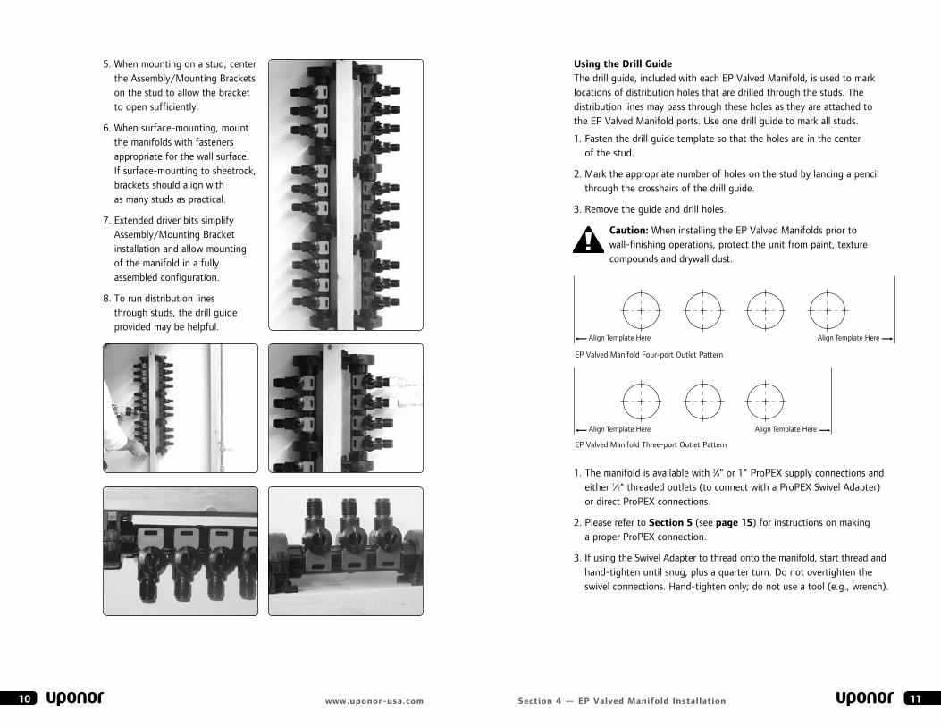
2. eP Valved manifolds are assembled with Flow-through Couplings (Q2121313) or Stop Couplings (Q2121251).
3. Insert the coupling into the end of the manifold until it stops. attach the next manifold to the coupling and install the assembly/mounting bracket (Q2120020).
4. Insert the 3⁄4" ProPeX Inlet (Q2120750) or 1" ProPeX Inlet (Q2121000) into the appropriate end of the manifold assembly. Install the assembly/ mounting bracket.
5. Insert the end Cap (Q2121250) into the other end of the manifold assembly. Install the assembly/mounting bracket.
6. ensure that all assembly/mounting brackets are fully locked, and the release tabs are located on the front (valve) side of the manifold.
7. For hot-water distribution, install the Red Valve Clips (Q2120001) prior to the manifold installation. Remove the blue Valve Clips (Q2120002) by grasping the clip and pulling up and away from the outlet. Rotating the clip away from the tab on the valve while pulling may simplify removal.
note: If insertion of components is difficult, lubricate the o-rings with a soapy water solution.
8 www.uponor-usa.com
assembly/mounting bracket
Flow-through Coupling
Stop Coupling
3⁄4" ProPeX Inlet 1" ProPeX Inlet
Red and blue Valve Clips
end Cap
using the drill Guide The drill guide, included with each eP Valved manifold, is used to mark locations of distribution holes that are drilled through the studs. The distribution lines may pass through these holes as they are attached to the eP Valved manifold ports. use one drill guide to mark all studs.
1. Fasten the drill guide template so that the holes are in the center of the stud.
2. mark the appropriate number of holes on the stud by lancing a pencil through the crosshairs of the drill guide.
3. Remove the guide and drill holes.
caution: When installing the eP Valved manifolds prior to wall-finishing operations, protect the unit from paint, texture compounds and drywall dust.
connecting Wirsbo aQuaPeX tubing to the eP valved manifold
1. The manifold is available with 3⁄4" or 1" ProPeX supply connections and either 1⁄2" threaded outlets (to connect with a ProPeX Swivel adapter) or direct ProPeX connections.
2. Please refer to section 5 (see page 15) for instructions on making a proper ProPeX connection.
3. If using the Swivel adapter to thread onto the manifold, start thread and hand-tighten until snug, plus a quarter turn. Do not overtighten the swivel connections. Hand-tighten only; do not use a tool (e.g., wrench).
11section 4 — eP valved manifold Installation
5. When mounting on a stud, center the assembly/mounting brackets on the stud to allow the bracket to open sufficiently.
6. When surface-mounting, mount the manifolds with fasteners appropriate for the wall surface. If surface-mounting to sheetrock, brackets should align with as many studs as practical.
7. extended driver bits simplify assembly/mounting bracket installation and allow mounting of the manifold in a fully assembled configuration.
8. To run distribution lines through studs, the drill guide provided may be helpful.
10 www.uponor-usa.com
Align Template Here Align Template Here
Align Template Here Align Template Here
eP Valved manifold Four-port Outlet Pattern
Align Template Here Align Template Here
Align Template Here Align Template Here
eP Valved manifold Three-port Outlet Pattern
filling and testing the eP valved manifold system system testair-pressure testing of an eP Valved manifold is acceptable and preferred to hydrostatic testing in areas where cold temperatures could freeze the system or where water is not available. uponor recommends that the installer pressurize the system with compressed air after installing and capping distribution lines.
note: eP Valved manifold valves must be in the open position prior and during the test, which should use a pressure of not less than working system pressure. Test the system for a minimum of 15 minutes. During the test, system pressure should drop no more than 8 psi in a one-hour period.
filling the system• Open all connected port valves before filling the system with water
and pressurizing.
• Take care when opening a port valve to an empty or unpressurized line. ensure the line connected to the fixture is in the OFF position. Open the valve slowly until water starts to flow into the line.
• Valve Cylinders (Q2120050) are replaceable.
note: Test the system to a minimum of working system pressure.
Warning: Pressures used in testing can blow unmade or incomplete connections apart with tremendous force. This force is many times greater when air is used as the test media. To reduce the risk of personal injury, ensure all connections are completed before testing. use only the pressure and time required to determine that the system is leak-free.
system disinfection eP manifolds and Wirsbo aQuaPeX tubing should be disinfected in accordance with aWWa C651-86, Standard for Disinfecting Water mains, or in accordance with local codes.
Warning: To prevent reduced service life of system components, disinfection solutions should not stand in the system longer than 24 hours. Flush the system with potable water after disinfection. Do not allow fluids to freeze in the eP Valved manifold System.
13section 4 — eP valved manifold Installation
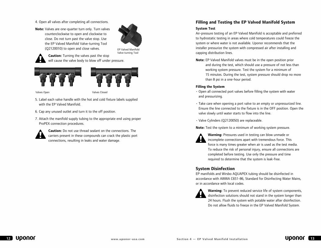
4. Open all valves after completing all connections.
note: Valves are one-quarter turn only. Turn valves counterclockwise to open and clockwise to close. Do not turn past the valve stop. use the eP Valved manifold Valve-turning Tool (Q2120010) to open and close valves.
caution: Turning the valves past the stop will cause the valve body to blow off under pressure.
5. label each valve handle with the hot and cold fixture labels supplied with the eP Valved manifold.
6. Cap any unused outlet and turn it to the off position.
7. attach the manifold supply tubing to the appropriate end using proper ProPeX connection procedures.
caution: Do not use thread sealant on the connections. The carriers present in these compounds can crack the plastic port connections, resulting in leaks and water damage.
12 www.uponor-usa.com
Valves Open Valves Closed
eP Valved manifold Valve-turning Tool
15section 5 — ProPeX fitting system
eP valve replacement
caution: make sure there is no pressure on the eP Valved manifold System prior to repair or replacement of any system components. all eP Valved manifolds come complete with assembled valves and their necessary o-rings. O-rings are required for proper valve operation.
1. Shut off water to manifold and bleed.
2. Remove the Red or blue Valve Clip by hand or using a small flat-head screwdriver.
3. Push the valve down (into manifold) as far as it will go and turn clockwise past the indent on the manifold.
4. use pliers to grip the handle of the valve if removal is difficult.
5. Pull the valve out of the manifold.
6. Place a small amount of soap and water solution on the o-rings on the replacement valve.
7. locate the tab on the valve so that it clears the indent on the manifold, and completely push in the valve.
8. Turn the valve past the indent on the manifold and pull up until it hits the stop.
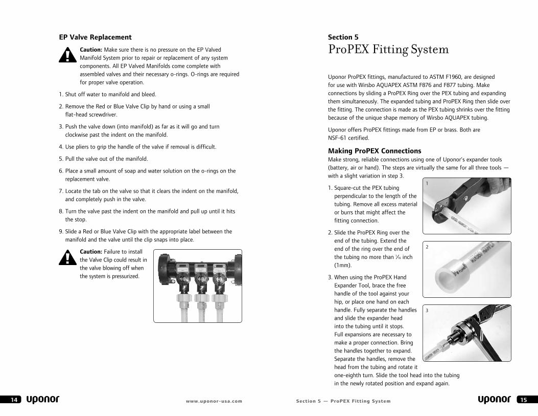
9. Slide a Red or blue Valve Clip with the appropriate label between the manifold and the valve until the clip snaps into place.
caution: Failure to install the Valve Clip could result in the valve blowing off when the system is pressurized.
14 www.uponor-usa.com
section 5
ProPEX Fitting System
uponor ProPeX fittings, manufactured to aSTm F1960, are designed for use with Wirsbo aQuaPeX aSTm F876 and F877 tubing. make connections by sliding a ProPeX Ring over the PeX tubing and expanding them simultaneously. The expanded tubing and ProPeX Ring then slide over the fitting. The connection is made as the PeX tubing shrinks over the fitting because of the unique shape memory of Wirsbo aQuaPeX tubing.
uponor offers ProPeX fittings made from eP or brass. both are NSF-61 certified.
making ProPeX connectionsmake strong, reliable connections using one of uponor’s expander tools (battery, air or hand). The steps are virtually the same for all three tools — with a slight variation in step 3.
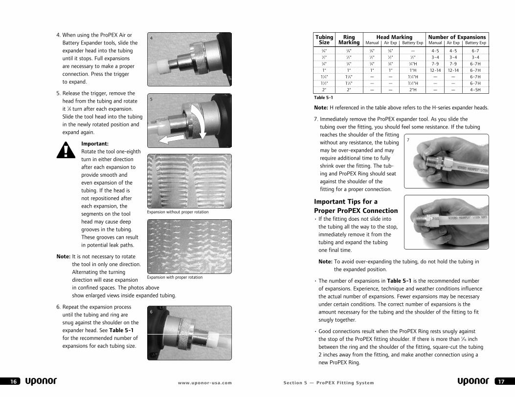
1. Square-cut the PeX tubing perpendicular to the length of the tubing. Remove all excess material or burrs that might affect the fitting connection.
2. Slide the ProPeX Ring over the end of the tubing. extend the end of the ring over the end of the tubing no more than 1⁄16 inch (1mm).
3. When using the ProPeX Hand expander Tool, brace the free handle of the tool against your hip, or place one hand on each handle. Fully separate the handles and slide the expander head into the tubing until it stops. Full expansions are necessary to make a proper connection. bring the handles together to expand. Separate the handles, remove the head from the tubing and rotate it one-eighth turn. Slide the tool head into the tubing in the newly rotated position and expand again.
1
2
3
note: H referenced in the table above refers to the H-series expander heads.
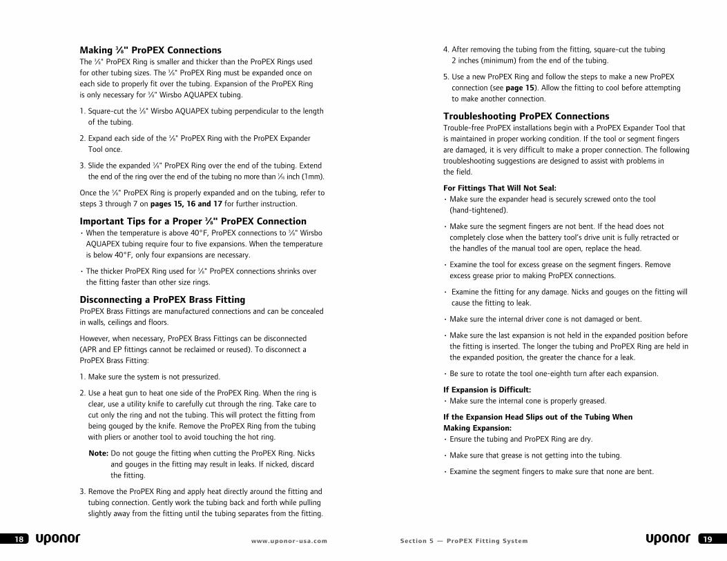
7. Immediately remove the ProPeX expander tool. as you slide the tubing over the fitting, you should feel some resistance. If the tubing reaches the shoulder of the fitting without any resistance, the tubing may be over-expanded and may require additional time to fully shrink over the fitting. The tub-ing and ProPeX Ring should seat against the shoulder of the fitting for a proper connection.
Important tips for a Proper ProPeX connection• If the fitting does not slide into
the tubing all the way to the stop, immediately remove it from the tubing and expand the tubing one final time.
note: To avoid over-expanding the tubing, do not hold the tubing in the expanded position.
• The number of expansions in table 5-1 is the recommended number of expansions. experience, technique and weather conditions influence the actual number of expansions. Fewer expansions may be necessary under certain conditions. The correct number of expansions is the amount necessary for the tubing and the shoulder of the fitting to fit snugly together.
• good connections result when the ProPeX Ring rests snugly against the stop of the ProPeX fitting shoulder. If there is more than 1⁄16 inch between the ring and the shoulder of the fitting, square-cut the tubing 2 inches away from the fitting, and make another connection using a new ProPeX Ring.
17section 5 — ProPeX fitting system
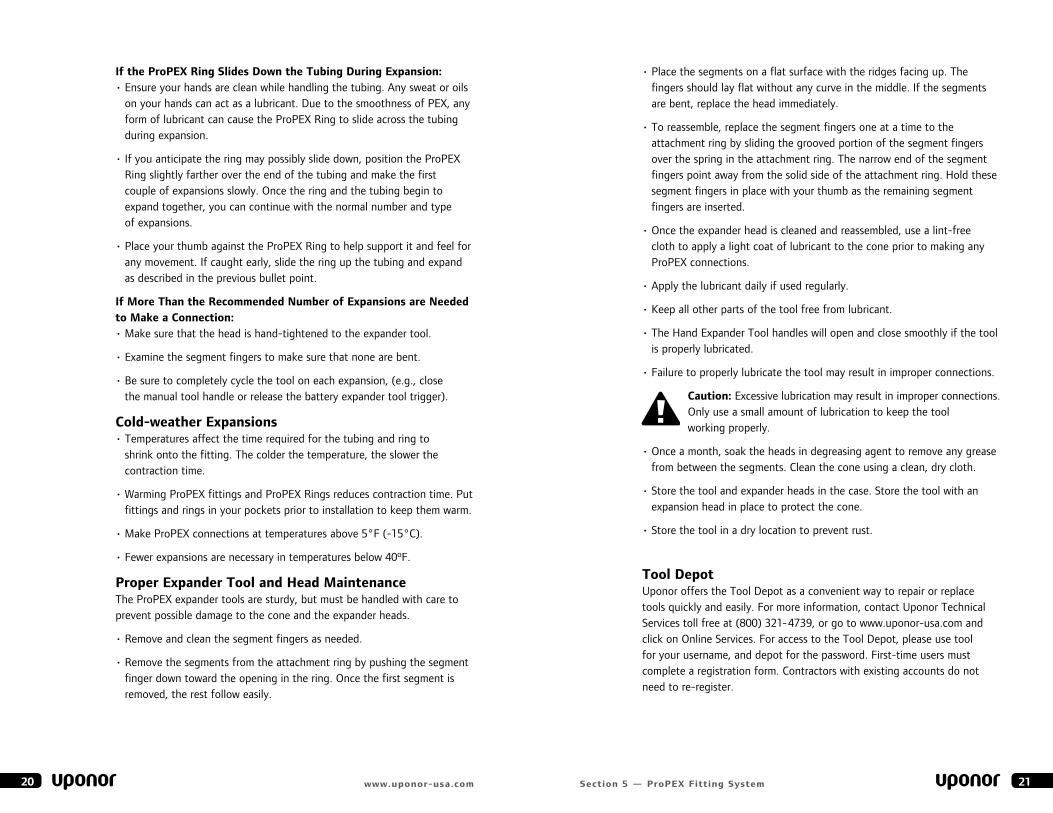
4. When using the ProPeX air or battery expander tools, slide the expander head into the tubing until it stops. Full expansions are necessary to make a proper connection. Press the trigger to expand.
5. Release the trigger, remove the head from the tubing and rotate it 1⁄8 turn after each expansion. Slide the tool head into the tubing in the newly rotated position and expand again.
Important: Rotate the tool one-eighth turn in either direction after each expansion to provide smooth and even expansion of the tubing. If the head is not repositioned after each expansion, the segments on the tool head may cause deep grooves in the tubing. These grooves can result in potential leak paths.
note: It is not necessary to rotate the tool in only one direction. alternating the turning direction will ease expansion in confined spaces. The photos above show enlarged views inside expanded tubing.
6. Repeat the expansion process until the tubing and ring are snug against the shoulder on the expander head. See table 5-1 for the recommended number of expansions for each tubing size.
16 www.uponor-usa.com
tubing ring Head marking number of expansions size marking manual air exp battery exp manual air exp battery exp
3⁄8" 3⁄8" 3⁄8" 3⁄8" — 4-5 4-5 6-7
1⁄2" 1⁄2" 1⁄2" 1⁄2" 1⁄2" 3-4 3-4 3-4
3⁄4" 3⁄4" 3⁄4" 3⁄4" 3⁄4"H 7-9 7-9 6-7H
1" 1" 1" 1" 1"H 12-14 12-14 6-7H
11⁄4" 11⁄4" — — 11⁄4"H — — 6-7H
11⁄2" 11⁄2" — — 11⁄2"H — — 6-7H
2" 2" — — 2"H — — 4 -5H
table 5-1
7
expansion with proper rotation
expansion without proper rotation
4
5
6
4. after removing the tubing from the fitting, square-cut the tubing 2 inches (minimum) from the end of the tubing.
5. use a new ProPeX Ring and follow the steps to make a new ProPeX connection (see page 15). allow the fitting to cool before attempting to make another connection.
troubleshooting ProPeX connections Trouble-free ProPeX installations begin with a ProPeX expander Tool that is maintained in proper working condition. If the tool or segment fingers are damaged, it is very difficult to make a proper connection. The following troubleshooting suggestions are designed to assist with problems in the field.
for fittings that Will not seal: • make sure the expander head is securely screwed onto the tool
(hand-tightened).
• make sure the segment fingers are not bent. If the head does not completely close when the battery tool’s drive unit is fully retracted or the handles of the manual tool are open, replace the head.
• examine the tool for excess grease on the segment fingers. Remove excess grease prior to making ProPeX connections.
• examine the fitting for any damage. Nicks and gouges on the fitting will cause the fitting to leak.
• make sure the internal driver cone is not damaged or bent.
• make sure the last expansion is not held in the expanded position before the fitting is inserted. The longer the tubing and ProPeX Ring are held in the expanded position, the greater the chance for a leak.
• be sure to rotate the tool one-eighth turn after each expansion.
If expansion is difficult:• make sure the internal cone is properly greased.
If the expansion Head slips out of the tubing When making expansion:• ensure the tubing and ProPeX Ring are dry.
• make sure that grease is not getting into the tubing.
• examine the segment fingers to make sure that none are bent.
19section 5 — ProPeX fitting system
making 3⁄8" ProPeX connectionsThe 3⁄8" ProPeX Ring is smaller and thicker than the ProPeX Rings used for other tubing sizes. The 3⁄8" ProPeX Ring must be expanded once on each side to properly fit over the tubing. expansion of the ProPeX Ring is only necessary for 3⁄8" Wirsbo aQuaPeX tubing.
1. Square-cut the 3⁄8" Wirsbo aQuaPeX tubing perpendicular to the length of the tubing.
2. expand each side of the 3⁄8" ProPeX Ring with the ProPeX expander Tool once.
3. Slide the expanded 3⁄8" ProPeX Ring over the end of the tubing. extend the end of the ring over the end of the tubing no more than 1⁄16 inch (1mm).
Once the 3⁄8" ProPeX Ring is properly expanded and on the tubing, refer to steps 3 through 7 on pages 15, 16 and 17 for further instruction.
Important tips for a Proper 3⁄8" ProPeX connection • When the temperature is above 40°F, ProPeX connections to 3⁄8" Wirsbo
aQuaPeX tubing require four to five expansions. When the temperature is below 40°F, only four expansions are necessary.
• The thicker ProPeX Ring used for 3⁄8" ProPeX connections shrinks over the fitting faster than other size rings.
disconnecting a ProPeX Brass fitting ProPeX brass Fittings are manufactured connections and can be concealed in walls, ceilings and floors.
However, when necessary, ProPeX brass Fittings can be disconnected (aPR and eP fittings cannot be reclaimed or reused). To disconnect a ProPeX brass Fitting:
1. make sure the system is not pressurized.
2. use a heat gun to heat one side of the ProPeX Ring. When the ring is clear, use a utility knife to carefully cut through the ring. Take care to cut only the ring and not the tubing. This will protect the fitting from being gouged by the knife. Remove the ProPeX Ring from the tubing with pliers or another tool to avoid touching the hot ring.
note: Do not gouge the fitting when cutting the ProPeX Ring. Nicks and gouges in the fitting may result in leaks. If nicked, discard the fitting.
3. Remove the ProPeX Ring and apply heat directly around the fitting and tubing connection. gently work the tubing back and forth while pulling slightly away from the fitting until the tubing separates from the fitting.
18 www.uponor-usa.com
• Place the segments on a flat surface with the ridges facing up. The fingers should lay flat without any curve in the middle. If the segments are bent, replace the head immediately.
• To reassemble, replace the segment fingers one at a time to the attachment ring by sliding the grooved portion of the segment fingers over the spring in the attachment ring. The narrow end of the segment fingers point away from the solid side of the attachment ring. Hold these segment fingers in place with your thumb as the remaining segment fingers are inserted.
• Once the expander head is cleaned and reassembled, use a lint-free cloth to apply a light coat of lubricant to the cone prior to making any ProPeX connections.
• apply the lubricant daily if used regularly.
• Keep all other parts of the tool free from lubricant.
• The Hand expander Tool handles will open and close smoothly if the tool is properly lubricated.
• Failure to properly lubricate the tool may result in improper connections.
caution: excessive lubrication may result in improper connections. Only use a small amount of lubrication to keep the tool working properly.
• Once a month, soak the heads in degreasing agent to remove any grease from between the segments. Clean the cone using a clean, dry cloth.
• Store the tool and expander heads in the case. Store the tool with an expansion head in place to protect the cone.
• Store the tool in a dry location to prevent rust.
tool depotuponor offers the Tool Depot as a convenient way to repair or replace tools quickly and easily. For more information, contact uponor Technical Services toll free at (800) 321-4739, or go to www.uponor-usa.com and click on Online Services. For access to the Tool Depot, please use tool for your username, and depot for the password. First-time users must complete a registration form. Contractors with existing accounts do not need to re-register.
21section 5 — ProPeX fitting system
If the ProPeX ring slides down the tubing during expansion:• ensure your hands are clean while handling the tubing. any sweat or oils
on your hands can act as a lubricant. Due to the smoothness of PeX, any form of lubricant can cause the ProPeX Ring to slide across the tubing during expansion.
• If you anticipate the ring may possibly slide down, position the ProPeX Ring slightly farther over the end of the tubing and make the first couple of expansions slowly. Once the ring and the tubing begin to expand together, you can continue with the normal number and type of expansions.
• Place your thumb against the ProPeX Ring to help support it and feel for any movement. If caught early, slide the ring up the tubing and expand as described in the previous bullet point.
If more than the recommended number of expansions are needed to make a connection:• make sure that the head is hand-tightened to the expander tool.
• examine the segment fingers to make sure that none are bent.
• be sure to completely cycle the tool on each expansion, (e.g., close the manual tool handle or release the battery expander tool trigger).
cold-weather expansions• Temperatures affect the time required for the tubing and ring to
shrink onto the fitting. The colder the temperature, the slower the contraction time.
• Warming ProPeX fittings and ProPeX Rings reduces contraction time. Put fittings and rings in your pockets prior to installation to keep them warm.
• make ProPeX connections at temperatures above 5°F (-15°C).
• Fewer expansions are necessary in temperatures below 40ºF.
Proper expander tool and Head maintenanceThe ProPeX expander tools are sturdy, but must be handled with care to prevent possible damage to the cone and the expander heads.
• Remove and clean the segment fingers as needed.
• Remove the segments from the attachment ring by pushing the segment finger down toward the opening in the ring. Once the first segment is removed, the rest follow easily.
20 www.uponor-usa.com
23section 6 — Plumbing Inspector’s checklist
section 6
Plumbing Inspector’s Checklist
This checklist is only intended to serve as a guideline to the local authority. It is not intended to include all applicable requirements. Please review the complete uponor Professional Plumbing Installation guide as well as local code for additional guidelines and restrictions. Where any conflict exists between this Installation guide and local code, the local code takes precedence.
tubing and fittings q Wirsbo aQuaPeX tubing — aSTm F876, aSTm F877, CSa b137.5,
NSF-PW.
q ProPeX fittings — manufactured and listed to CSa b137.5.
manifolds q eP Valved manifolds are NSF Certified to NSF-PW.
q an eP Valved manifold system, which has valves on all the outlet ports, does not require stop valves at the fixtures. However, the code official may require stop valves at some fixtures.
q Provide access to the eP Valved manifold and its mounting screws, the port valves, distribution-line connections and supply-line connections.
q The main service line to the eP Valved manifold should include a main shut-off valve.
q When the eP Valved manifold is mounted above the water heater, install a minimum of 36 inches of connecting tubing between the water heater and the eP Valved manifold due to possible heat stacking.
q When the eP Valved manifold is mounted beside the water heater and is connected with tubing incorporating a horizontal flow, connect with at least 18 inches of tubing.
q Individual fixture shut-off valves at the manifold should identify the fixture being supplied.
Handling Guidelines for eP fittings although not comprehensive, the following highlights the most common guidelines to use when handling eP fittings:
• Do not solder within 18 inches of any eP fittings in the same water line. Sweat connections must be made prior to making the ProPeX connection.
• Do not subject eP fittings to impact.
• Do not use adhesives or adhesive tape with eP fittings.1
• Do not expose eP fittings to open flame.
• Do not allow solder, flux, pipe dope, solvents or urethane foams to come in contact with eP fittings as immediate damage may result.
• Never pull or drag tubing by the installed eP fittings.
• Do not expose eP fittings to excessive bending loads (greater than 100 lbs.).
• Do not use eP fittings where temperatures and pressures exceed ratings.
• Do not spray on or allow organic chemicals, strong acids or strong bases to come into contact with eP fittings.
• Do not use petroleum or solvent-based paints on eP fittings.
• Do not allow rodents, insects or other pests to come into contact with eP fittings.
1 you may temporarily affix adhesive tape to eP fittings during installation. However, to protect the integrity of the system, the tape should not be permanent. Remove the tape and residual adhesive after completing the installation.
22 www.uponor-usa.com
25section 6 — Plumbing Inspector’s checklist
General recommendations q Protect Wirsbo aQuaPeX tubing passing through hollow masonry walls
or metal studs with sleeves or grommets.
q Protect Wirsbo aQuaPeX tubing from damage (e.g., nail, screw, etc.) with suitable steel-plate protectors.
q The minimum bend radius of PeX is six times the outside diameter.
Pressure testing q Open the valves on the eP Valved manifold prior to pressure testing.
These valves are to remain open until the pressure test is complete.
q Pressure-test the system with air or water to the system working pressure (40 to 60 psi) at the current ambient temperature. Pressure testing should not exceed 100 psi. Slight fluctuations of pressure are normal due to ambient temperature changes.
caution: If using water to pressure-test the system, purge all water from the system prior to ambient air temperatures nearing 32ºF (0ºC). Failing to remove the water from the system can result in damage to the tubing and associated equipment.
tubing limitations q Do not expose Wirsbo aQuaPeX tubing to direct sunlight for more than
30 days.
q Do not install Wirsbo aQuaPeX tubing within 6 inches of any gas appliance vents or within 12 inches of recessed light fixtures.
q Do not install Wirsbo aQuaPeX tubing within 12 inches of recessed light fixtures, unless the PeX line is protected with suitable insulation.
Joints and connections q Square-cut all tubing ends and ensure they are free of burrs or debris
before a connection is made.
q ensure fittings and connections comply with the manufacturers’ recommendations.
q make transition joints with manufacturer-approved fittings.
ProPeX fittings q Fully seat the Wirsbo aQuaPeX tubing and ProPeX Ring against the
shoulder of the fitting. The maximum gap should be no more than the thickness of a credit card.
q If an improper connection is made, cut 2 inches from the tubing and use a new ProPeX Ring.
tubing supports q use plastic or metal supports designed for use with plastic tubing.
q Place horizontal support every 32 inches for 3⁄8", 1⁄2", 3⁄4" and 1" PeX tubing.
q Provide vertical support every 4 to 5 feet with a mid-story guide placed between floors.
q bends within 6 inches of a ProPeX connection to 3⁄8" to 1⁄2" tubing and within 10 inches of a ProPeX connection to 3⁄4" to 1" tubing require support.
q allow 1⁄8 to 3⁄16 inches of slack per foot of run on installed Wirsbo aQuaPeX tubing for expansion and contraction.
q Wirsbo aQuaPeX tubing should not be rigidly anchored. anchor the tubing to allow freedom of movement for expansion and contraction.
24 www.uponor-usa.com

26 www.uponor-usa.com
notes