plumbing diagram - international
TRANSCRIPT

Plumbing diagram - International
1 –Wood-burning stove in an Open vented system
Description Code
Wood-burning stove /
Open vented vessel with safety and loading pipe n.s.
1.5 bar safety valve (not required but recommended)601200
3
¾” 90°C/3 bar safety valve and thermal discharge for open vented systems (not required but recommended)
6012005
Temperature gauge n.s.
Pressure gauge n.s.
System separator kit:
Stove controller with circulator control probe and acoustic alarm*;
Circulator for primary circuit (P1);
Circulator for secondary circuit (P2).
6012027
Stove controller with circulator control probe and acoustic alarm* (if you do not want to provide the system separator kit)
6012022
* Note: With the Digital Stove Controller (code 6012022), two NTC probes (code 7025514; length 5 metres) canbe ordered as accessories to control the temperature and manage a boiler and a buffer (for diagrams refer to thecontroller manual).
rev. 04FB07052018

Plumbing diagram - International
rev. 04FB07052018

Plumbing diagram - International
2 – Wood thermo-product in a close pressure system and hydraulic system separator
Description Codice
Thermo-product /
DSA automatic thermal discharge valve for stoves supplied with solid fuels (¾” female connection) - OPTIONAL
7118403
3 bar safety valve (not required but recommended)601202
3
Temperature gauge n.d.
Pressure gauge n.d.
Close pressure vessel n.d.
System separator kit:
Stove controller with circulator control probe and acoustic alarm*;
Circulator for primary circuit (P1);
Circulator for secondary circuit (P2).
6012027
Stove controller with circulator control probe and acoustic alarm* (if you do not want to provide the system separator kit)
6012022
* Note: With the Digital Stove Controller (code 6012022), two NTC probes (code 7025514; length 5 metres) canbe ordered as accessories to control the temperature and manage a boiler and a buffer (for diagrams refer to thecontroller manual).
rev. 04FB07052018

Plumbing diagram - International
3 - Wood-burning stove in a Close pressurized system
Description Code
Stove /
DSA automatic thermal discharge valve for stoves supplied with solid fuels (¾” female connection) - OPTIONAL
7118403
3 bar safety valve 6012023
Temperature gauge n.s.
Pressure gauge n.s.
Close pressurized vessel n.s.
Stove controller with circulator control probe and acoustic alarm *
6012022
Circulator pump n.s.
55°C Anti-condensation mixing valve for recirculation circuit, - REQUIRED
7118402
10 Balancing valve n.s.
rev. 04FB07052018

Plumbing diagram - International
* Note: With the Digital Stove Controller (code 6012022), two NTC probes (code 7025514; length 5 metres) canbe ordered as accessories to control the temperature and manage a boiler and a buffer (for diagrams refer to thecontroller manual).
4 –Wood-burning stove in an Open vented system and Buffer tank
Description Code
Stove /
Open pressurized vessel with safety and loading tube n.s.
1.5 bar Safety valve(not required but recommended)601200
3
¾” 90°C / 3 bar safety valve and thermal discharge for open vented systems (not required but recommended)
6012005
Temperature gauge n.s.
Pressure gauge n.s.
System separator kit:
Stove controller with circulator control probe and acoustic alarm*;
Circulator for primary circuit (P1);
Circulator for secondary circuit (P2).
6012027
Stove controller with circulator control probe and acoustic alarm* (if you do not want to provide the system separator kit)
6012022
Technical water tank (Buffer) to be sized based on the characteristics of the chosen Stove (see sizing table)
/
Heating system flow manifold n.s.
Heating system return manifold n.s.
rev. 04FB07052018

Plumbing diagram - International
* Note: With the Digital Stove Controller (code 6012022), two NTC probes (code 7025514; length 5 metres) canbe ordered as accessories to control the temperature and manage a boiler and a buffer (for diagrams refer to thecontroller manual).
rev. 04FB07052018

Plumbing diagram - International
5 –Wood-burning stove in a Close pressurized system and Buffer tank
Description Code
Stove /
DSA automatic thermal discharge valve for Stoves supplied with solid fuels (¾” female connection) - OPTIONAL
7118403
3 bar safety valve 6012023
Temperature gauge n.s.
Pressure gauge n.s.
Close pressurized vessel n.s.
Stove controller with circulator control probe and acoustic alarm *
6012022
Circulator pump n.s.
55°C Anti-condensation mixing valve for recirculation circuit, - REQUIRED
7118402
10 Balancing valve n.s.
11Technical water tank (Buffer) to be sized based on the characteristics of the chosen stove (see sizing table)
/
12 Heating system flow manifold n.s.
13 Heating system return manifold n.s.
* Note: With the Digital Stove Controller (code 6012022), two NTC probes (code 7025514; length 5 metres) canbe ordered as accessories to control the temperature and manage a boiler and a buffer (for diagrams refer to thecontroller manual).
rev. 04FB07052018

Plumbing diagram - International
rev. 04FB07052018
Plumbing diagram - International
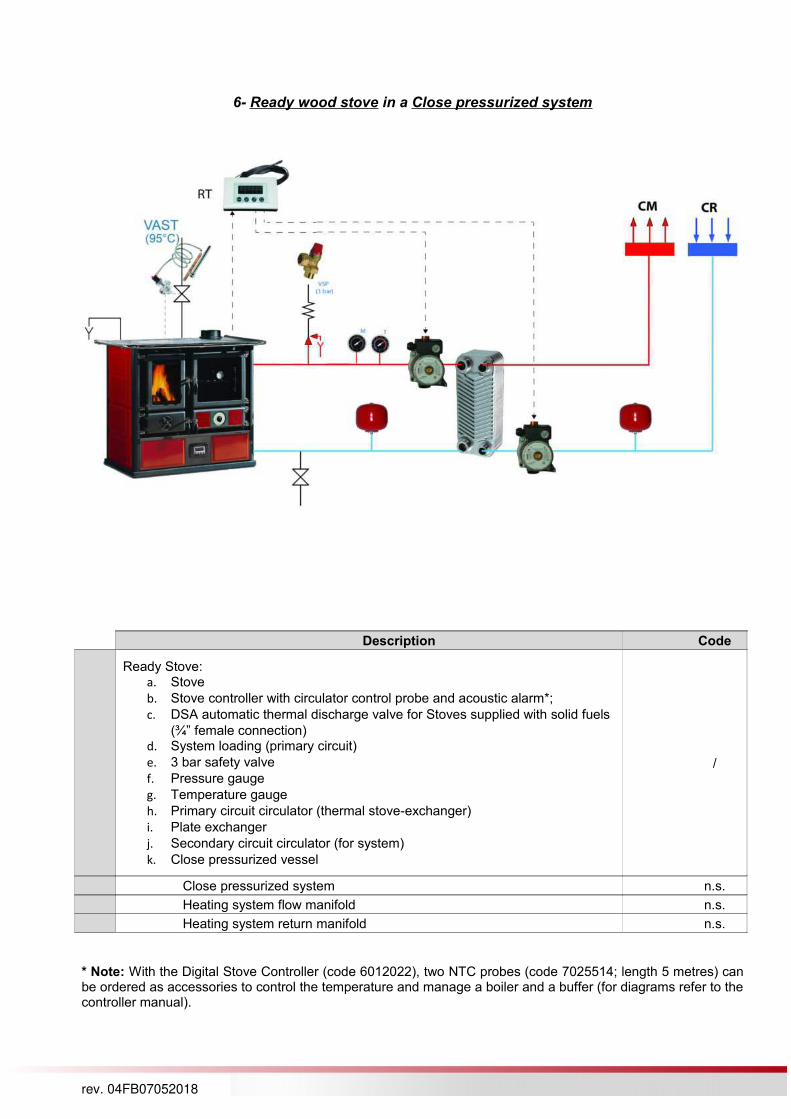
6- Ready wood stove in a Close pressurized system
Description Code
Ready Stove:a. Stove
b. Stove controller with circulator control probe and acoustic alarm*;
c. DSA automatic thermal discharge valve for Stoves supplied with solid fuels
(¾” female connection)d. System loading (primary circuit)
e. 3 bar safety valve
f. Pressure gauge
g. Temperature gauge
h. Primary circuit circulator (thermal stove-exchanger)
i. Plate exchanger
j. Secondary circuit circulator (for system)
k. Close pressurized vessel
/
Close pressurized system n.s.
Heating system flow manifold n.s.
Heating system return manifold n.s.
* Note: With the Digital Stove Controller (code 6012022), two NTC probes (code 7025514; length 5 metres) canbe ordered as accessories to control the temperature and manage a boiler and a buffer (for diagrams refer to thecontroller manual).
rev. 04FB07052018
Plumbing diagram - International
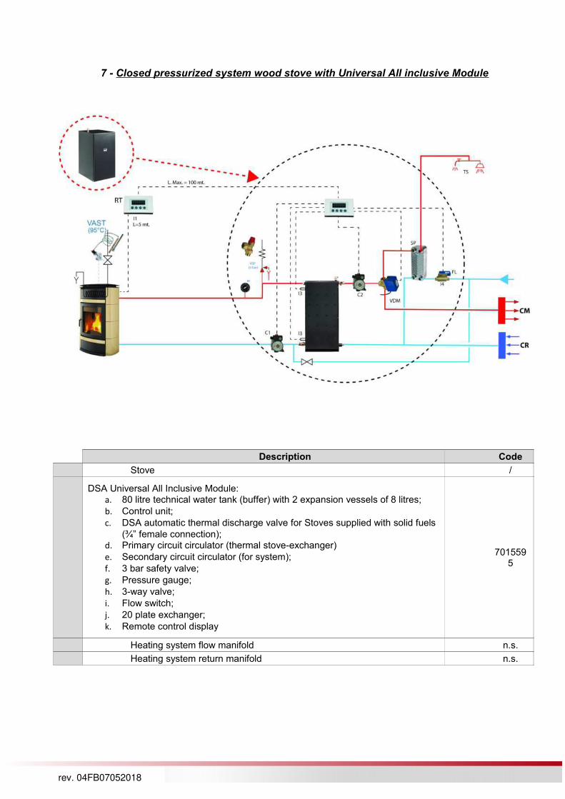
7 - Closed pressurized system wood stove with Universal All inclusive Module
Description Code
Stove /
DSA Universal All Inclusive Module:a. 80 litre technical water tank (buffer) with 2 expansion vessels of 8 litres;
b. Control unit;
c. DSA automatic thermal discharge valve for Stoves supplied with solid fuels
(¾” female connection);d. Primary circuit circulator (thermal stove-exchanger)
e. Secondary circuit circulator (for system);
f. 3 bar safety valve;
g. Pressure gauge;
h. 3-way valve;
i. Flow switch;
j. 20 plate exchanger;
k. Remote control display
7015595
Heating system flow manifold n.s.
Heating system return manifold n.s.
rev. 04FB07052018

Plumbing diagram - International
8 –Reversed flame boiler in a Close pressure system and Buffer tank
Description Codice
LNK Series reversed flame boiler /
DSA automatic thermal discharge valve for Stoves supplied with solid fuels (¾” female connection)
7118403
3 bar safety valve 6012023
Temperature gauge n.d.
Pressure gauge n.d.
Close pressure vessel n.d.
Circulator n.d.
60°C Anti-condensation mixing valve for recirculation circuit, - REQUIRED
7118404
Balancing valve n.d.
10Technical water tank (Buffer) to be sized based on the characteristics of the chosen stove (see sizing table)
n.d.
11Buffer tank probe (supplied with boiler)Important: the position is indicative. The real one has to be evaluated with the installer/designer
/
12 Gas boiler n.d.
13 Radiator system (high temperature) n.d.
14 Radiant panel system (low temperature) n.d.
15 Solar panels n.d.
rev. 04FB07052018

Plumbing diagram - International
9 – Pellet stove in a close pressurized system
Description Code
Pellet Stove /
Temperature gauge n.s.
Pressure gauge n.s.
Close pressurized vessel n.s.
, 55°C Anti-condensation mixing valve for recirculation circuit - REQUIRED
9208213
Balancing valve n.s.
rev. 04FB07052018

Plumbing diagram - International
10 – Pellet stove in a close pressurized system and dhw tank
Description Code
Pellet-burning stove /
Temperature gauge n.s.
Pressure gauge n.s.
Closed pressurized vessel n.s.
55°C Anti-condensation mixing valve for recirculation circuit, - REQUIRED
9208213
Balancing valve n.s.
3-way valve n.s.
DHW tank: to be sized based on the number of people (see sizing table) /
rev. 04FB07052018

Plumbing diagram - International
rev. 04FB07052018

Plumbing diagram - International
11 –Pellet stove in a close pressurized system and Buffer
Description Code
Pellet-burning stove /
Temperature gauge n.s.
Pressure gauge n.s.
Close pressurized vessel n.s.
55°C Anti-condensation mixing valve for recirculation circuit - REQUIRED 9208213
Balancing valve n.s.
Gas boiler n.s.
Technical water tank (Buffer) to be sized based on the characteristics of the chosen stove (see sizing table)
/
Radiator system (high temperature) /
10 Radiant panel system (low temperature) /
rev. 04FB07052018

Plumbing diagram - International
12 –Pellet stove with system expansion board and DHW tank
Description Code
Pellet-burning stove (model compatible with system expansion board) /
Temperature gauge n.s.
Pressure gauge n.s.
Close pressurized vessel n.s.
55°C Anti-condensation mixing valve for recirculation circuit - REQUIRED 9208213
Balancing valve n.s.
System expansion board kit 9278286
3-way valve n.s.
Hydraulic compensator n.s.
10 DHW tank: to be sized based on the number of people (see sizing table) /
11Radiator system (high temperature); 4 zones with zone valve managed by room thermostats
/
rev. 04FB07052018

Plumbing diagram - International
13 –Pellet stove with system expansion board and Buffer
Description Code
Pellet-burning stove (model compatible with system expansion board) /
Temperature gauge n.s.
Pressure gauge n.s.
Close pressurized vessel n.s.
55°C Anti-condensation mixing valve for recirculation circuit - REQUIRED 9208213
Balancing valve n.s.
System expansion board kit 9278286
Gas boiler (controlled by system expansion board) n.s.
Technical water tank (Buffer) to be sized based on the characteristics of the chosen stove (see sizing table)
/
10Radiator system (high temperature); 4 zones with circulator controlled by room thermostats
/
rev. 04FB07052018

Plumbing diagram - International
14 –Pellet stove with plumbing system separator kit
Description Code
Pellet-burning stove /
Temperature gauge and pressure gauge n.s.
Plumbing System Separator Kit:a. Flow pipe temperature control probe
b. Return pipe temperature control probe
c. Plate exchanger
d. Regulation and control unit
e. System circulator
9278359
Gas boiler n.s.
Heating system controlled with thermostats n.s.
rev. 04FB07052018