plenum box installation instructions · 7960-545f page 3 of 7 figure 3 qw heating capacity notes: j...
TRANSCRIPT

7960-545F
Page 1 of 7
PLENUM BOX
INSTALLATION INSTRUCTIONS
Models:
QPBHW42-D-V-MOD QPBHW48-D-V-MOD
QPBHW42-F-V-MOD QPBHW48-F-V-MOD
QPBHW42-D-4-MOD QPBHW48-D-4-MOD
QPBHW42-F-4-MOD QPBHW48-F-4-MOD
QPBHW42-D-X-MOD QPBHW48-D-X-MOD
QPBHW42-F-X-MOD QPBHW48-F-X-MOD
Copyright July 2006
The Plenum Box is designed for use with the Q-Tec Series units. It is for use in Ducted applications
depending on the model specified.
1. Remove the center screw from each top side of the unit.
2. Cut insulation 6.5 inches back and 1.5 inches in. Install grommet in .875 hole in Q-Tec top. See
Figure 1 and Figure 2.
3. Place Plenum Box on top of Q-Tec unit with the open side down & the grille facing the front of the unit.
4. Make sure that the bottom offsets of the Plenum Box are inside the top of the Q-Tec unit flange. The
outside of the Plenum Box should be flush with the outside of the unit.
5. Reinstall the center screws in the top of the Q-Tec unit. These screws will go through the clearance
holes on the Plenum Box and hold it in place.
6. Remove side access panel. Route field-supplied control wiring into unit low voltage area and up
through top bushing to the valve.
7. Adjust louvers to obtain desired air distribution.
8. Connect supply and return piping. Return is on the left facing the front of the unit. Supply is on the
right facing the front of the unit.
Bard Manufacturing Company, Inc.
Bryan, Ohio 43506

7960-545F
Page 2 of 7
FIGURE 1
FREE BLOW PLENUM
FIGURE 1
DUCTED PLENUM
7960-545F
Page 3 of 7
FIG
UR
E 3
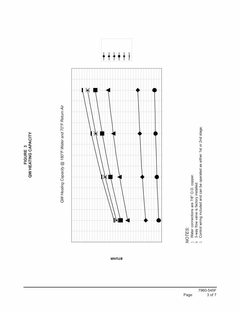
QW
HE
AT
ING
CA
PA
CIT
Y
NOTES:
jW
ate
r connections a
re 7
/8"
O.D
. copper.
k3-w
ay f
low
valv
e is f
acto
ry insta
lled.
lC
ontr
ol w
irin
g inclu
ded a
nd c
an b
e o
pera
ted a
s e
ither
1st
or
2nd s
tage.
QW
Heatin
g C
apacity
@ 1
80°F
Wate
r and 7
0°F
Retu
rn A
ir
30000
40000
50000
60000
70000
80000
90000
100000
700
800
900
1000
1100
1200
1300
1400
1500
CF
M
BTU/HR
1.5G
PM
2G
PM
4G
PM
6G
PM
8G
PM
10G
PM
7960-545F
Page 4 of 7

7960-545F
Page 5 of 7

7960-545F
Page 6 of 7

7960-545F
Page 7 of 7