please contact your retailer or email support@redrotorrc...
TRANSCRIPT


2
Return Policy– Without soldering anything to the board, please apply power to the
board using alligator clips and make sure the Green LED is on. Contact us immediately
if green LED doesn't turn on! Return and Warranty claims are only considered on units
that have not been soldered and within 30 days of purchase date.
Connecting any external voltages to the RROSD 5V rail will destroy the board and
effectively void warranty.
Disclaimer!! - Please understand that quadcopters are potentially dangerous machine.
Use the highest level of precaution when working with hot solder iron, Lipo battery and
motors. Make sure to remove props from motor throughout the entire building process.
Solder equipment – Be sure to use a high quality soldering iron with a large tip
especially when soldering the battery and ESC connections.
Power output on CAM 5V/12V connector – Because a linear regulators are used, limit
the current draw to less than 500mA on 12V and 250mA on 5V rail to prevent
overheating
6S battery – Please make sure VTX solder bridge is set to RAW to prevent the 12V
regulator from going into thermal shutdown
Solder Bridge setting – Please make sure the middle pad is only making connection to
either left or right pad. Soldering all 3 pads together will effectively destroy your RROSD
Pro!
Battery Polarity – Be sure to hook up your battery leads to the proper pads. Positive
lead is clearly marked with ++++ and Negative lead with ----. Reversing this can
potentially damage your board
Power/Ground wire soldering – Caution must be taken when soldering wires to the
power and ground pads on the PDB. There are many sensitive components on the
PDB board that a hot soldering iron can ruin or de-solder if carelessly placed

3
What is RROSD-PRO PDB?
Simply put, the RROSD PRO PDB is an easy to use power distribution board and OSD designed
to maximize FPV experience while minimizing mini quad build time and reducing the wire
clutter mess!
Built-in features
Thick copper and wide power routing to handle the most demanding power setup
Dimension 36mm x 36mm (30.5mm x 30.5mm mounting holes)
Built-in power distribution regulators to handle 3S-6S
Built in multi stages power filter for Video Transmitter and Camera with pre-installed
and conveniently located connectors
12V and 5V output: can be used for FPV cam and accessories
NTSC and PAL can be easily selected using the onboard button
Plug and Play (PnP) OSD information: Flight pack voltage, current draw, total current
consumption, RSSI, flight timer, Lap counter&timer
Maximum motor current 100A total
Automatic flight timer shows actual flight time
The additional lost model buzzer sounds off 5 minutes after the quad has crashed.
RSSI detection (FRsky ppm and analog compatible) displays in percentage
Auto Battery alarm blinks the battery voltage when pack voltage hits the low limit
Low RSSI turns on Buzzer (very handy to locate a downed quad)
Onscreen menu allows user to calibrate pack voltage reading, current calibration, rssi
input, battery alarm level…etc....
Lap Timer onscreen counter (requires fw v4.0 or newer)
Firmware upgradable to ensure any user can enjoy any new features that we might
release the future (optional programmer is needed)
Lost model Siren (optional Buzzer)

4
PDB Connection Diagram
BATT + => Flight battery positive input 3S – 6S
BATT - => Flight battery negative input
ESC + => ESCs positive input (top and bottom)
ESC- => ESCs negative input (top and bottom)
LED => Indicator led
Select Button => Function selection button
Front Connector Pin Description:
1. Ground
2. +12V regulated FPV camera, 500mA max
3. Video Signal
4. Ground
5. +5V regulated (flight controller), 250mA max *Do not connect any external
voltages to this pin, it will destroy the RROSD

5
6. RSSI Input – Use a female-female servo cable to connect to the receiver RSSI
signal, pwm and analog compatible. There’s a built in signal conditioning circuit to
convert pwm rssi to analog voltage. Example: ch-2 on Frsky D4R receiver
7. Buzzer +5
8. Buzzer Ground
Solder Bridge Setting:
1. VTX – Connect Middle pad and ‘RAW’ or ‘12V’ pad to set VTX voltage to
Battery input and regulated 12V respectively. *Do not short all 3 pads together
or very bad things will happen
2. CAM – Connect middle pad to ‘5V’ or ‘12V” pad to set CAM voltage. *Do not
short all 3 pads together or very bad things will happen
Rear Connector Pin Description:
A. Ground
B. Video transmitter filtered regulated 12V power
C. Video transmitter video signal
D. Programmer DTR signal
E. Programmer RX signal
F. Programmer TX signal/Lap-Timer Input
*These Instructions apply to the latest FW release only. All boards are loaded with the latest release from the
factory.
Hold down the Button for 10 seconds upon powering up the RROSD Pro. The LED will flash 5 times
to indicate that the Video mode has been successfully changed
To enter into the menu of the RROSD, power up the board and hold down on the button on
The RROSD Pro board within 3 seconds of powering up. Keep it depressed until the menu
appears in your view then release.
To navigate through the menu single click the button to move down an option. Long press to
select an option
RSSI Calibration: To calibrate your RSSI reading, select the high reading with your radio and
receiver powered on and nearby. Flip off the radio and select the low reading to calibrate the
6
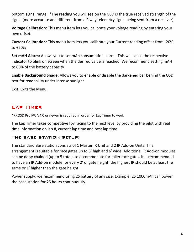
bottom signal range. *The reading you will see on the OSD is the true received strength of the
signal (more accurate and different from a 2 way telemetry signal being sent from a receiver)
Voltage Calibration: This menu item lets you calibrate your voltage reading by entering your
own offset.
Current Calibration: This menu item lets you calibrate your Current reading offset from -20%
to +20%
Set mAH Alarm: Allows you to set mAh consumption alarm. This will cause the respective
indicator to blink on screen when the desired value is reached. We recommend setting mAH
to 80% of the battery capacity
Enable Background Shade: Allows you to enable or disable the darkened bar behind the OSD
text for readability under intense sunlight
Exit: Exits the Menu
*RROSD Pro FW V4.0 or newer is required in order for Lap Timer to work
The Lap Timer takes competitive fpv racing to the next level by providing the pilot with real
time information on lap #, current lap time and best lap time
The standard Base station consists of 1 Master IR Unit and 2 IR Add-on Units. This
arrangement is suitable for race gates up to 5’ high and 6’ wide. Additional IR Add-on modules
can be daisy chained (up to 5 total), to accommodate for taller race gates. It is recommended
to have an IR Add-on module for every 2’ of gate height, the highest IR should be at least the
same or 1’ higher than the gate height
Power supply: we recommend using 2S battery of any size. Example: 2S 1000mAh can power
the base station for 25 hours continuously

7

8

9
Recommended IR modules arrangement for a 5’x6’ air gate

10

11
Mounting the Transponder: Choosing the location to mount the transponder is very critical in
order to avoid missing counts when crossing the Base station. The transponder should be
mounted in a way that the IR sensor faces outward and has a clear view of the Base station IRs
when it passes through the gate. The sensor should be mounted as high and away from any
obstacle (including props) as much as possible. Keep in mind that banking the quad at an extreme
angle while crossing the Base station might result in missed detection

12
The Transponder can also be remotely mounted…
The RROSD Pro auto configs the OSD text to display the appropriate Lap Timer information
when the transponder is connected

13
Download the Firmware Upgrade Utility software from
http://redrotorrc.com/download/RRLoader_V4.zip
Unzip and run the installer (RRLoader.msi)
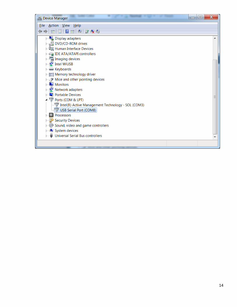
Connect the USB-to-Serial dongle (RR-PRGM) to a PC running Win XP/7/8 and make
note of the installed COM #
You can also go Device Manager to find out the COM number
14

15
Connect the USB dongle to RROSD Expansion port as shown. Make sure the
battery is unplugged from your RROSD Pro.
Launch the RR Loader shortcut and enter the correct port Number.
Plug battery into RROSD Pro. (not time sensitive)
Choose the correct COM number, and click “Load”
16
Remove power and disconnect programmer from RROSD when firmware loading is
finished and gives you a success message.
Power up RROSD Pro and the OSD version listed on initial boot-up on the on screen
display should be updated if everything worked correctly.
If you get an error message make sure you COM port is correct and you’ve followed
instructions exactly. Try a different USB port or PC and try the alternate method
The onboard LED can provide useful information to help trouble shoot the RR
LED Behavior:
Stays full on: this means the RROSD is running but not getting valid video signal from
the camera. Check camera cable
Blinks steadily: this is an indication that the RROSD is running properly and getting valid
video input. Check VTX cabling and make sure channels are set correctly. Check VTX antenna
to make sure there’s no short
LED not on when powered up: RROSD isn’t running. Check battery input cable and
make sure battery is charged