plc melsec
DESCRIPTION
mtshubishi melsec plcTRANSCRIPT

PROGRAMMABLE LOGIC
CONTROLLER

MELSEC-AnS, QnASMELSEC-AnS, QnAS
Compact size controller

Control I/O sizeControl I/O size
256
512
1024
8192
A1S
J
A1S
A2S
A2A
SQ
2AS
(H)
A1S
-S1
A2S
-S1
A2
AS
-S1
,S3
0,S
60
,M1
28
Q2A
S(H
)-S1
Q2A
S(H
) (Vertual I/O
)A
2AS
(Vertual I/O
)
A2A
S-S
(Vertual I/O
)
Q2A
S(H
) (Vertual
I/O)

Program execution speedProgram execution speed
Processing speed of 1 contact/coil command
0.075us
A1S
J
A1S
A2S
A2A
SQ
2AS
A1S
-S1
A2S
-S1
A2A
S-S
1
1usA
2AS
-S30
0.2us
Q2A
SH
Q2A
S-S
1Q
2AS
H-S
1
0.15us A2A
S-S
60
,M1
28

MELSEC-QnA/QnASMELSEC-QnA/QnAS
Innovation of programming
ConceptConcept
Structured programmingProgram standardizationSimplification of program
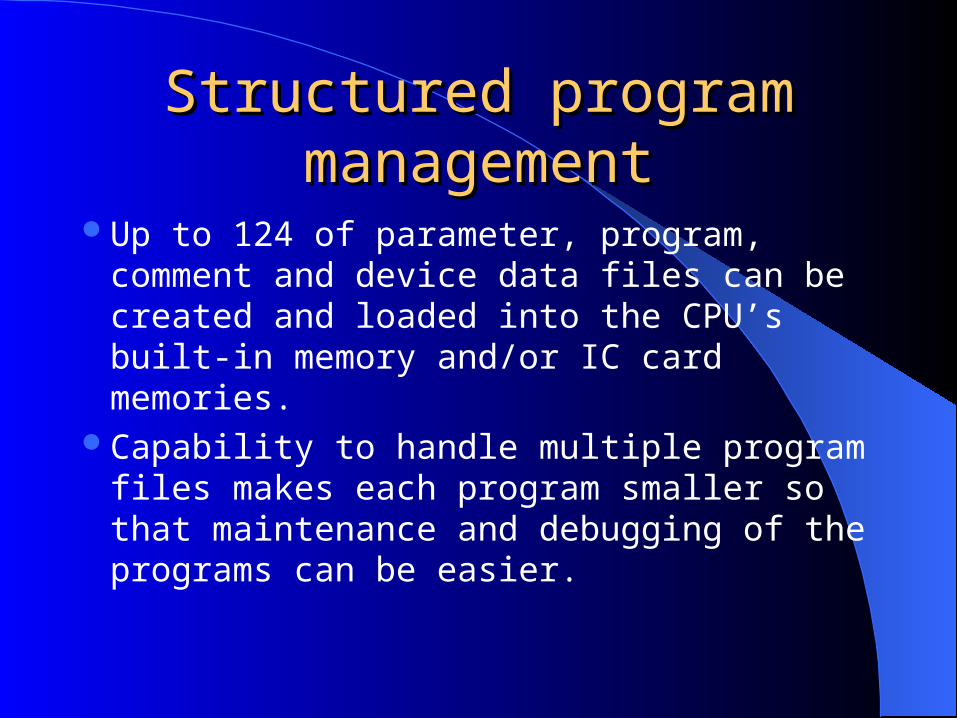
Structured program Structured program managementmanagement
Up to 124 of parameter, program, comment and device data files can be created and loaded into the CPU’s built-in memory and/or IC card memories.
Capability to handle multiple program files makes each program smaller so that maintenance and debugging of the programs can be easier.

Structured program Structured program managementmanagement
Designer A
Designer B
Designer C
Programs divided based on designer
Program A
Program B
Program C
QnA CPU
Feed-in process
Assembly process
Feed-out process
Programs divided based on process
Program A
Program B
Program C
QnA CPU

Structured program Structured program managementmanagement
Simultaneous debugging
Program A Program B
While a designer is debugging Program A via the CPU front port,another designer can debug Program B via AJ71QC24.

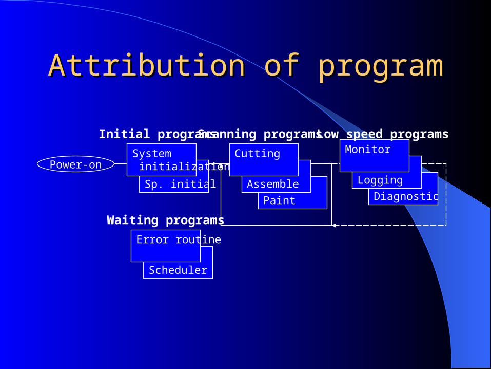
Attribution of programAttribution of program
Initial program– Programs only once after power-on
Scanning program– Programs executed repeatedly
Low speed program– Programs executed in the constant scan loop
Waiting program– Programs executed when initiated by interrupts or
subroutine calls
Paint
Sp. initial
Attribution of programAttribution of program
Power-onSystem initialization
Assemble
Cutting
Diagnostic
Logging
Monitor
Scheduler
Error routine
Initial programs Scanning programs Low speed programs
Waiting programs

Structured program Structured program managementmanagement
Global device & Local device
X0 X0M0
X1 X2M100
X1 X2
Program A
B0 X100M0
Program B
M100
Because M0 is a local device, M0 in Program A and M0 in Program B can operate independently.Because M100 is a global device, status of M100 in Program A is relayed to M100 in Program B.
Note: Range of each device type as local device can be defined by the user

Structured program Structured program managementmanagement
Global device & Local device– Local devices can be assigned in the following
devices Internal relay M Edge relay V Timer T Retentive timer ST Counter C Data register D

Program standardizationProgram standardization
Macro command– A program block often used in a program can
be registered as a user-defined macro command

Program standardizationProgram standardization
Subroutine call with arguments– A subroutine program can be called from
another program with input arguments and output arguments, similar to ‘function call ‘ of C language.

Program standardizationProgram standardization
Subroutine call with arguments
X0
Main routine program
[CALL P0 M1 M2 D0 ]FX0
Sub routine
[MOV FD1 R0 ]FX0
FY1M0
P0
[RET ]
Up to 5 arguments can be used

Simplification of programSimplification of program
Programming with labels
‘Start ‘Stop‘Ready
‘Ready
Label Device Comment[Start] [X0 ] [System start ][Stop] [X1 ] [Cycle stop ]
[Ready] [Y10 ] [Operation ready ]
X0 X1Y10
Y10
When program Label definition
Converter to program

Simplification of programSimplification of program
New data devices– Bit specification of a register device
X0 D0.0D0.A
b15 b14 b13 b12 b11 b10 b9 b8 b7 b6 b5 b4 b3 b2 b1 b0

Simplification of programSimplification of program
New data devices– Direct access input and output
X0 DX10DY100
Output is made when the command is executed.
Input is made when the command is executed.
Input is made in the end of scan.

Simplification of programSimplification of program
New data devices– Differential contact
X0 X1
Y100
X0 contact in the program only close for one scan after X0 changes its status from OFF to ON.
In the conventional program, PLS command has toused to make a equivalent program.
Y100

Simplification of programSimplification of program
New data devices– Direct addressing of special function module
X0[MOV U5\G12 D0 ]
U5: Signifies a special module located on address X/Y50G12: Signifies address 12 of the special module
In a conventional program, FROM/TO command has to be used instead.

Simplification of programSimplification of program
New data devices– Character strings
X0[$+P D5 “-S1” R10 ]
D5 - D8
+ “-S1”“Q2ACPU”
R10 - R14
“Q2ACPU-S1”

Simplification of programSimplification of program
Device initial data– QnA can hold a device initial data file where
initial setting data of devices are registered, and transfers this data into device memory when the CPU is set to RUN.
– This feature eliminates programs which set initial data in the devices and the buffer memory of special modules

Simplification of programSimplification of program
Device initial dataInitialization program
(Conventional method)
[MOV H100 D0 ]
[MOV H200 D1 ]
[TO H2 K100 H100 K1 ]
Device initial data file
Device memoryT, ST, C, D, W
Sp. modulebuffer memory

Hardware FeaturesHardware Features
High speed processing
A4UCPU Q4ACPUContact/ Coil 0.15 s 0.075 s
MOV 0.90 s 0.225 s
On average, Q4ACPU is approx.. 3 times faster than A3A/A3U/A4UCPU.
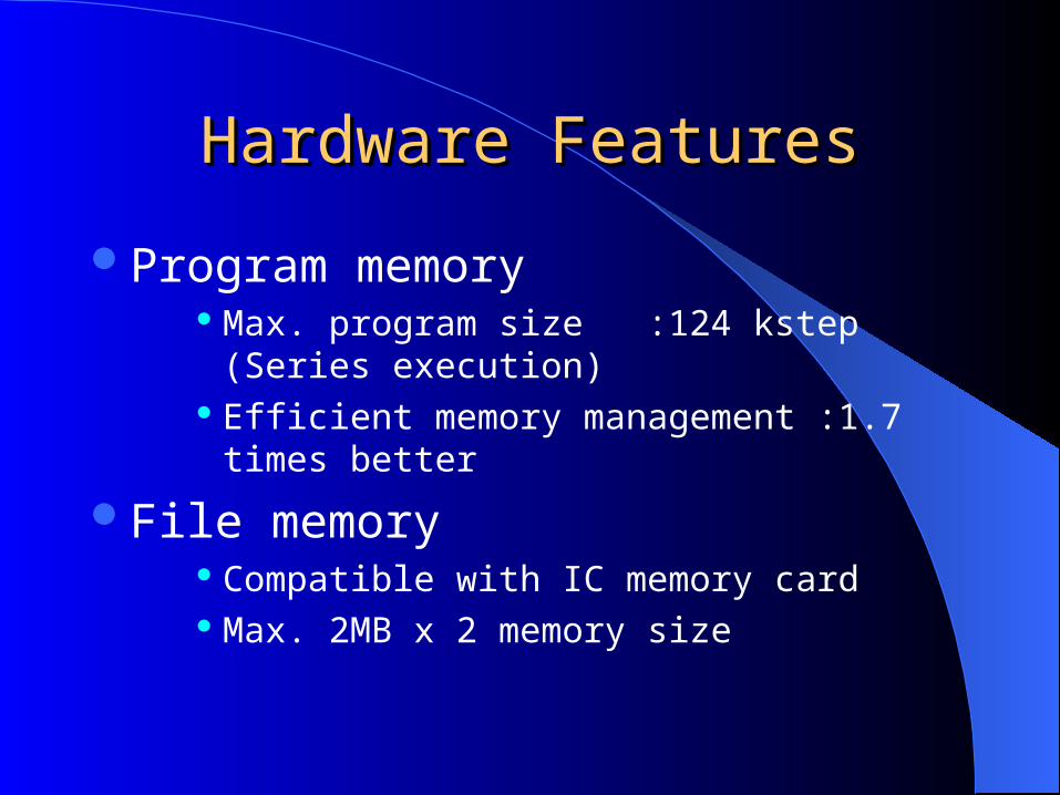
Hardware FeaturesHardware Features
Program memory Max. program size :124 kstep (Series execution) Efficient memory management :1.7 times better
File memory Compatible with IC memory card Max. 2MB x 2 memory size

Q4ACPU : 4096 I/O, 124kstep, 0.075us/step Q3ACPU : 2048 I/O, 92kstep, 0.15us/step Q2ACPU-S1: 1024 I/O, 60kstep, 0.15us/step Q2ACPU : 512I/O, 28kstep, 0.2us/step
QnA Series CPU modulesQnA Series CPU modules

Network modulesNetwork modules
AJ71QLP21, AJ71QLP21S : MELSECNET/10 AJ72QLP25 : MELSECNET/10 AJ71QBR11 : MELSECNET/10 AJ72QBR15 : MELSECNET/10 AJ71QC24/R2/R4 :RS232C/485
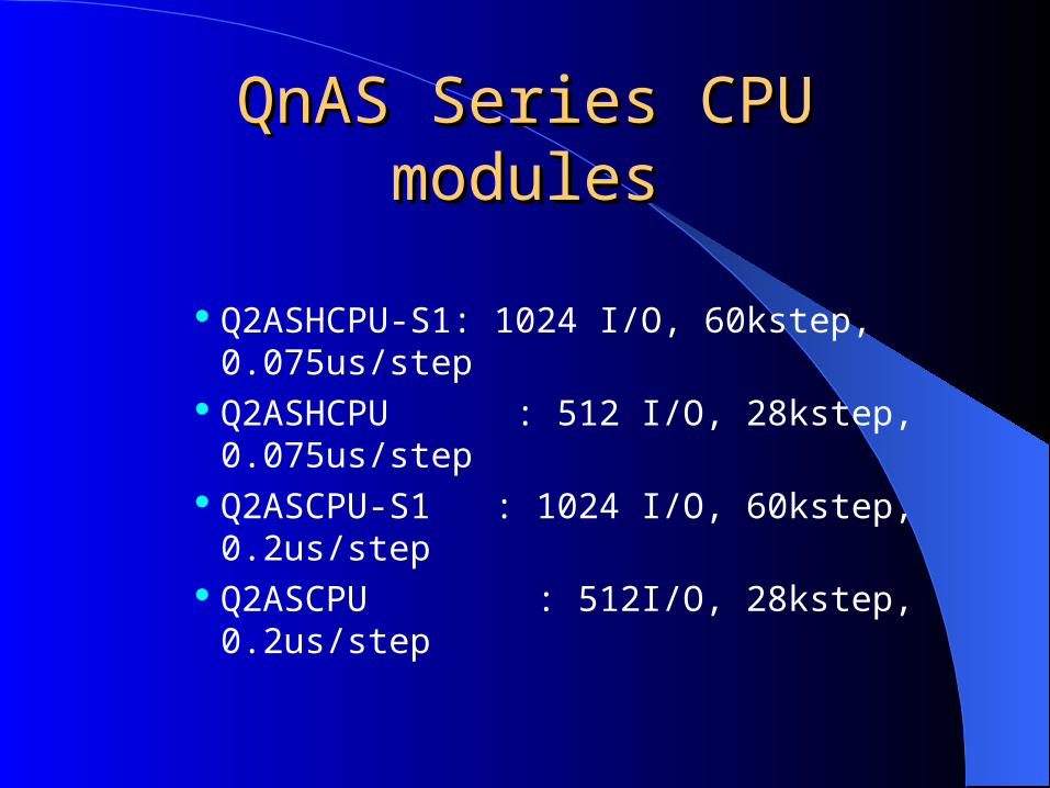
QnAS Series CPU modulesQnAS Series CPU modules
Q2ASHCPU-S1: 1024 I/O, 60kstep, 0.075us/step Q2ASHCPU : 512 I/O, 28kstep, 0.075us/step Q2ASCPU-S1 : 1024 I/O, 60kstep, 0.2us/step Q2ASCPU : 512I/O, 28kstep, 0.2us/step

Q4ARCPU SystemQ4ARCPU System
A Hot/Stand-by systemMitsubishi Electric Corporation

Q4ARCPU SystemQ4ARCPU System

Q4ARCPU SystemQ4ARCPU System
Single system:Utilize Q4AR’s extended calculation ability
Dual system:Configuration of a hot/stand-by system and/or utilize Q4AR’s extended calculation ability

Q4ARCPUQ4ARCPUSingle system configuration

Q4ARCPUQ4ARCPUSingle system configuration
Powersupply
A38HB base rack required
A6
1R
P

Q4ARCPUQ4ARCPUSingle system configuration
CPU
A38HB base rack required
A6
1R
P
Q4A
R

Q4ARCPUQ4ARCPUSingle system configuration
I/O modules
A38HB base rack required
A6
1R
P
Q4A
R

Q4ARCPUQ4ARCPUSingle system configuration w/dual power
supply

Q4ARCPUQ4ARCPUSingle system configuration w/dual power
supply
Powersupply
Powersupply
A37RHB base rack required
A6
1R
PA
61R
P

Q4ARCPUQ4ARCPUSingle system configuration w/dual power
supply
CPU
A37RHB base rack required
A6
1R
PA
61R
P
Q4A
R

Q4ARCPUQ4ARCPUSingle system configuration w/dual power
supply
I/O modules
A37RHB base rack required
A6
1R
PA
61R
P
Q4A
R

Q4ARCPUQ4ARCPUDual system configuration

Q4ARCPUQ4ARCPUDual system configuration
Powersupply
Powersupply
A33RB base rack required
A6
1R
P
A6
1R
P

Q4ARCPUQ4ARCPUDual system configuration
CPU CPU
A33RB base rack required
A6
1R
P
A6
1R
P
Q4A
R
Q4A
R

Q4ARCPUQ4ARCPU
Systemmonitor
Systemmonitor
BUS I/F
Dual system configuration
A33RB base rack required
Q4A
R
Q4
AR
A6
RA
F
AS
92
R
AS
92
R

Q4ARCPUQ4ARCPU
Network Network
Dual system configuration
MELSECNET/10
A33RB base rack required
Q4A
R
Q4
AR
A6
RA
F
AS
92
R
AS
92
R
QB
R1
1
QB
R1
1
A6
1R
P
A6
1R
P

Q4ARCPUQ4ARCPU
Network Network
Dual system configuration
MELSECNET/10MELSECNET/10
A33RB base rack required
Q4A
R
Q4
AR
A6
RA
F
AS
92
R
AS
92
R
QB
R1
1
QB
R1
1
A6
1R
P
A6
1R
P
QB
R1
1
QB
R1
1

Q4ARCPUQ4ARCPU
MELSECNET/10
ExtensionRack
Dual system configuration
MELSECNET/10
A33RB base rack required
Q4A
R
Q4
AR
A6
RA
F
AS
92
R
AS
92
R
QB
R1
1
QB
R1
1
A6
1R
P
A6
1R
PQ
BR
11
QB
R1
1
A6
1R
PA
61R
P

Q4ARCPUQ4ARCPU
MELSECNET/10
Dual system configuration
MELSECNET/10
I/O modules
A33RB base rack required
Q4
AR
Q4
AR
A6
RA
F
AS
92
R
AS
92
R
QB
R1
1
QB
R1
1
A6
1R
P
A6
1R
PQ
BR
11
QB
R1
1
A6
1R
PA
61R
P

ConfigurationConfigurationOver all system
MELSECNET/10 remote I/O net, or PLC net
MELSECNET/10 PLC net
QN
A

Specifications: Q4ARCPUSpecifications: Q4ARCPU
Processing speed of sequence command: 0.075us/step.
Max. No. of input/output points: 4096 pointsWith remote I/O system; up to 8192 I/O control
Program capacity: 124K steps
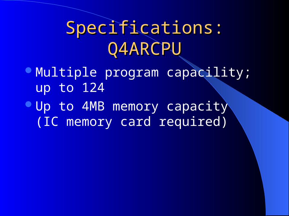
Specifications: Q4ARCPUSpecifications: Q4ARCPU
Multiple program capacility; up to 124Up to 4MB memory capacity
(IC memory card required)

Data TrackingData Tracking
Data necessary for back-up are copied every scan to the stand-by CPU via the data tracking bus so that seamless control at hot-stand-by switching time is realized.– Up to 48kW data tracking per scan
On-line program tracking– Program change to the active CPU is copied to
the stand-by CPU

Duplicated NetworkDuplicated Network
This system is fully compatible to the MELSECNET/10 high speed duplicated network system.
MELSECNET/10 redundancy– By cable disconnection– By network module failure

Extended self-diagnostic Extended self-diagnostic functionsfunctions
Power supply 5VDC voltage dropPower supply 24VDC voltage dropPower supply failure detectionCPU self-diagnosticsAS92R’s CPU healthy check

New process commandsNew process commands
S.IN Analog inputS.OUT1 Output with mode switchingS.PID Basic PIDS.PHPL Upper/lower limit alarmS.LLAG Leading lagS.I IntegrationS.D DerivativeS.DED Dead timeS.FG Function generationS.IFG Function reverse generationS.FLT FilterS.ENG Engineering value conversionS.IENG Engineering value reverse conversionS.ABS Absolute

Math co-processorMath co-processor
For high speed floating point math calculation
Command A3ACPU Q4ACPU Q4ARCPU+ 476 us 238 us 35 us- 482 us 241 us 35 us 228 us 114 us 35 us 746 us 373 us 38 us
SIN 4620 us 2310 us 34 usCOS 4920 us 2460 us 34 usTAN 4970 us 2485 us 37 us
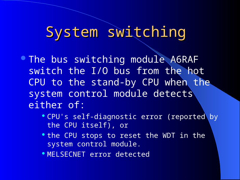
System switching System switching
The bus switching module A6RAF switch the I/O bus from the hot CPU to the stand-by CPU when the system control module detects either of:
CPU's self-diagnostic error (reported by the CPU itself), or
the CPU stops to reset the WDT in the system control module.
MELSECNET error detected

Module SpecificationsModule Specifications
AS92R: System control module CPU operations are monitored. Monitor of power supply module’s +5V output. CPU health check with WDT counter.
A61RP: Power supply module Duplicated power supply unit. Performance equivalent to A61P. DC5V output drop detection function..
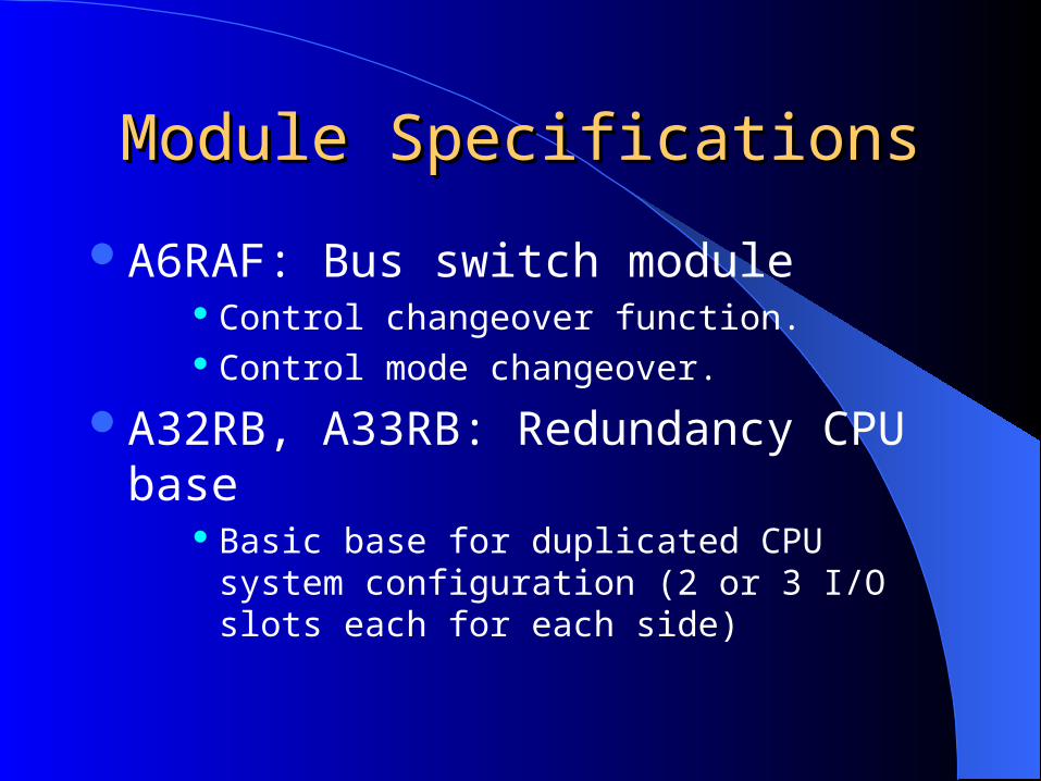
Module SpecificationsModule Specifications
A6RAF: Bus switch module Control changeover function. Control mode changeover.
A32RB, A33RB: Redundancy CPU base Basic base for duplicated CPU system configuration
(2 or 3 I/O slots each for each side)

Module SpecificationsModule Specifications
A37RHB: PS redundancy base A37RHB for single CPU system with duplicated
power supply modules (7 I/O slots)
A68RB: Extension base 8 I/O slots with duplicated power supply modules
– The connection of the I/O bus to a CPU can be switched manually by the switch located on the bus switching module.

Redundancy ByRedundancy ByMELSECNET-10MELSECNET-10
Mitsubishi Electric Corporation

A1S
61PN
MN
ET
-10
Q2A
SC
PU
A1S
61PN
MN
ET
-10
Q2A
SC
PU
A1S32BA1S32B
A1S
61PN
MN
ET
-10
A1S
X41
-S2
A1S
X41
-S2
A1S
Y41
A1S38B
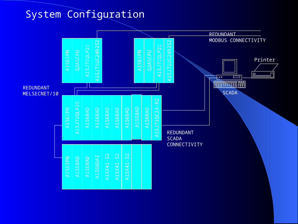
System Configuration
A1
S6
1P
N
Q2
AS
CP
U
A1
SJ7
1Q
LP
21
A1
SJ7
1U
C2
4R
2S
2
A1
S6
1P
N
Q2
AS
CP
U
A1
SJ7
1Q
LP
21
A1
SJ7
1U
C2
4R
2S
2
A1
S6
1P
N
A1
SJ7
2Q
LP
25
A1
SJ7
1Q
C2
4-R
2
A1
S6
8A
D
A1
S6
8A
D
A1
S6
8A
D
A1
S6
8A
D
A1
S6
8A
D
A1
S6
8A
D
A1
S6
8A
D
A1
S6
1P
N
A1
S6
8A
D
A1
S6
8D
AI
A1
SX
41
-S2
A1
SX
41
-S2
A1
SX
41
-S2
A1
S6
8A
D
Printer
SCADA
REDUNDANT MODBUS CONNECTIVITY
REDUNDANT MELSECNET/10
REDUNDANT SCADA CONNECTIVITY
System Configuration

A1
S6
1P
N
MN
ET
-10
A1
SJ7
1Q
C2
4
A6
1P
A6
8R
D3
/4
A6
16
AD
A6
16
AD
A6
16
AD
A6
8R
D3
/4Printer
SCADA /Application software
System configuration
A68B
A1S38B
A1
SC
07
NB
A1
S6
1P
N
CC
-Lin
k A1S68B
A1S58B
A1
SC
07
BA
1S
C0
7B
Remote I/O modules AJ65-SBTB1-32D, DI modules.AJ65-SBTB1-32T, DO modules.
. . . . . .
I/Os
I/Os
I/Os
A1
S6
1P
N
Q2
AS
CP
U
MN
ET
-10
A1
S6
1P
N
Q2
AS
CP
U
MN
ET
-10

A
1S
61
PA
1S
61
P
Q2
AS
CP
UQ
2A
SC
PU
A1
SJ7
1Q
LP
21
A1
SJ7
1Q
LP
21
A1
SJ7
1Q
C2
4-R
4A
1S
J71
QC
24
-R4
A1
S6
1P
A1
S6
1P
Q2
AS
CP
UQ
2A
SC
PU
A1
SJ7
1Q
LP
21
A1
SJ7
1Q
LP
21
A1
SJ7
1Q
C2
4-R
4A
1S
J71
QC
24
-R4
A1
S6
1P
A1
S6
1P
A1
SJ7
2Q
LP
25
A1
SJ7
2Q
LP
25
A1
SX
42
A1
SX
42
A1
SX
42
A1
SX
42
A1
SX
42
A1
SX
42
A1
SX
42
A1
SX
42
A1
SY
42
A1
SY
42
A1
SY
42
A1
SY
42
A1
SY
42
A1
SY
42
A1
SY
42
A1
SY
42
ETHERNET
System configuration

A1
S6
1P
A1
S6
1P
Q2
AS
CP
UQ
2A
SC
PU
A1
SJ6
1Q
BT
11
A1
SJ6
1Q
BT
11
A1
SJ7
1C
24
-R4
S2
A1
SJ7
1C
24
-R4
S2
A1
S6
1P
A1
S6
1P
Q2
AS
CP
UQ
2A
SC
PU
A1
SJ6
1Q
BT
11
A1
SJ6
1Q
BT
11
A1
SJ7
1C
24
-R4
S2
A1
SJ7
1C
24
-R4
S2
ETHERNET
System configuration

Questions ?
Thank you Thank you for listeningfor listening