plc forensics based on control program logic change detection
TRANSCRIPT
Journal of Digital Forensics, Journal of Digital Forensics,
Security and Law Security and Law
Volume 10 Number 4 Article 5
2015
PLC Forensics Based on Control Program Logic Change Detection PLC Forensics Based on Control Program Logic Change Detection
Ken Yau University of Hong Kong
Kam-Pui Chow University of Hong Kong
Follow this and additional works at: https://commons.erau.edu/jdfsl
Part of the Computer Engineering Commons, Computer Law Commons, Electrical and Computer
Engineering Commons, Forensic Science and Technology Commons, and the Information Security
Commons
Recommended Citation Recommended Citation Yau, Ken and Chow, Kam-Pui (2015) "PLC Forensics Based on Control Program Logic Change Detection," Journal of Digital Forensics, Security and Law: Vol. 10 : No. 4 , Article 5. DOI: https://doi.org/10.15394/jdfsl.2015.1211 Available at: https://commons.erau.edu/jdfsl/vol10/iss4/5
This Article is brought to you for free and open access by the Journals at Scholarly Commons. It has been accepted for inclusion in Journal of Digital Forensics, Security and Law by an authorized administrator of Scholarly Commons. For more information, please contact [email protected].
(c)ADFSL
brought to you by COREView metadata, citation and similar papers at core.ac.uk
provided by Embry-Riddle Aeronautical University

PLC Forensics Based on Control Program Logic Change … JDFSL V10N4
© 2015 ADFSL Page 59
PLC FORENSICS BASED ON CONTROLPROGRAM LOGIC CHANGE DETECTION
WORKSKen Yau and Kam-Pui Chow
University of Hong Kong, Hong Kong, [email protected], [email protected]
ABSTRACTSupervisory Control and Data Acquisition (SCADA) system is an industrial control automatedsystem. It is built with multiple Programmable Logic Controllers (PLCs). PLC is a special form ofmicroprocessor-based controller with proprietary operating system. Due to the unique architectureof PLC, traditional digital forensic tools are difficult to be applied. In this paper, we propose aprogram called Control Program Logic Change Detector (CPLCD), which works with a set ofDetection Rules (DRs) to detect and record undesired incidents on interfering normal operationsof PLC. In order to prove the feasibility of our solution, we set up two experiments for detectingtwo common PLC attacks. Moreover, we illustrate how CPLCD and network analyzer Wiresharkcould work together for performing digital forensic investigation on PLC.Keywords: PLC Forensics, SCADA Security, Ladder Logic Programming
INTRODUCTIONDigital forensics plays an important role forincident investigations on digital devices, forexample, personal computer, smart-phone,digital camera, and flash drive. Standardguidelines and procedures are provided toimplement the digital forensic processes:identification, collection, analysis and reporting[11]. According to the collected evidence,investigators can re-construct the incident andpresent to a court if crime is involved. Inaddition, the evidence can be used to tracewhat causes the incidents in order to avoid thesame incident happening again in the future[2].
A programmable logic controller (PLC) is aspecial form of microprocessor-based controller.It uses a programmable memory to storeinstructions and to implement functions such
as logic, sequencing, timing, counting andarithmetic in order to control machines andprocesses [1]. Lighting Control system is oneexample of PLC applications. It is used to turnlights on automatically when the area becomesoccupied and off when it becomes unoccupied.
A simple automation control system can bemonitored and controlled by a single PLC.However, a complex and larger automationcontrol system called Supervisory Control andData Acquisition (SCADA) system, needs tobe built with multiple PLCs. SCADA system isan automation system widely used to monitorand control industrial processes such as electricpower generation, public transportation,chemical plants, water management and so on.If any undesired incidents occur on theSCADA systems, substantial risk to the healthand safety of human lives, serious damage tothe environment, as well as serious financial

JDFSL V10N4 PLC Forensics Based on Control Program Logic Change …
Page 60 © 2015 ADFSL
issues such as production losses, negativeimpact to a nation’s economy, and compromiseof proprietary information [2].
SCADA systems are always built withproprietary technologies and communicationprotocols. For example, PLC manufacturersprovide its proprietary operating systems totheir products. Due to the uniqueness ofSCADA system, there are several challengeswhen performing digital forensic processes onthese systems. Those challenges will bediscussed in Section 4. In this paper, wepropose a solution to detect and recordabnormal operations of PLC based on thecontrol program logic change in PLC. Theabnormal operations are stored in the formatof a log file which could help SCADA forensicinvestigation.
SECURITY ISSUES OFPLC
An automation control system can be setup byconnecting a PLC with Input and Outputdevices. Input devices might be switches,temperature sensors, flow sensors, etc. Outputdevices might be motors, solenoid valves, etc.Besides hardware installation, the PLC has tobe programmed in order to monitor the inputsand control the outputs based on a set ofcontrol rules. Each PLC manufacturer has itsown software for programming their PLCs. Forexample, PLCs of Siemens Simatic S7 seriesare programmed, configured, and managedusing software STEP 7.
Nowadays, many PLCs have evolved toutilize common networking standard such asEthernet (IEEE 802.3) and Wi-Fi (IEEE802.11) for communication among theconnected devices [3]. Therefore, cyber-attackson SCADA systems become one of theimportant security issues after the systemshave been exposed to the Internet.
ATTACKS ON PLCSThere are various kinds of attacks on PLCs.One of the famous attacks is STUXNET, amalware to infect Simatic programming device(i.e., PC running Step 7 on Windows). Themalware was used to reprogram the PLCs byinserting its own blocks of code, and replacingor infecting existing blocks [6]. According tothe paper “Exploiting Siemens Simatic S7PLCs” [3], Dillon Beresford mentioned that thenetwork protocols designed for communicationamong field devices in control systems wereintended to be open and reliable, but notsecure in past. International StandardsOrganization Transport Service Access Point(ISO-TSAP RFC 1006) is one of the not securenetwork protocols.
Dillon Beresford demonstrated severalattacks on Siemens Simatic S7 PLCs duringthe presentation at Black Hat 2011 Conference.The attacks were 1) TCP Replay over ISO-TSAP Attack; 2) S7 Authentication Bypass; 3)CPU Stop and Start Attack; 4) Memory Readand Write Logic Attack; 5) DecryptingSiemens Simatic firmware; 6) Getting a Shellon the PLC. The exploits demonstrated byBeresford were using PROFINET andcommunicating across TCP/IP port 102 (ISO-TSAP).
PROFINET is a standard for IndustrialEthernet based on Industrial Ethernet andsupport the following three protocols [9]:
1. TCP/IP with reaction times in therange of 100 ms
2. RT (real-time) protocol with 10 mscycle times
3. IRT (Isochronous Real-Time) withcycles times of less than 1 ms
Data is transmitted in plain text overTCP/IP port 102 (ISO-TSAP). Therefore, ifattackers record the network traffic, they couldeasily extract data such as user names,
PLC Forensics Based on Control Program Logic Change … JDFSL V10N4
© 2015 ADFSL Page 61
passwords, commands, negotiated sessions,logic, etc. Any of these variables could lead aPLC to be compromised.
DIGITAL FORENSICSCHALLENGES ONSCADA SYSTEMS
Cyber forensics can be challenging when beingapplied to non-traditional environments likeSCADA systems. The systems are notcomprised of current information technologiesand not designed with technologies to provideadequate data storage or audit capabilities. Inaddition, further complexity is introduced ifthe environment is designed using proprietarysolutions and protocols, thus limiting the easeof which modern forensic methods can beutilized [11].
Due to the complexity of SCADA systems,evidence is difficult or impossible to beextracted and collected by using traditionaldigital forensics for investigation. One of thechallenges is that the operations of SCADAsystems must be kept running, therefore,investigators cannot shut down the system toperform data acquisition [2]. In such situation,live forensics is the possible way to performdata acquisition. However, performing liveforensics on SCADA systems might affect itsnormal operations. The second challenge isthat many SCADA systems use proprietaryand legacy software, hardware andcommunication protocols. Therefore,traditional digital forensic tools might not beable to apply to the systems. Furthermore,SCADA forensics is lack of event logs forinvestigation
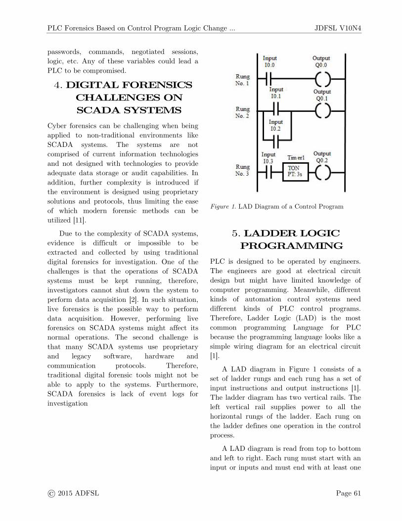
Figure 1. LAD Diagram of a Control Program
LADDER LOGICPROGRAMMING
PLC is designed to be operated by engineers.The engineers are good at electrical circuitdesign but might have limited knowledge ofcomputer programming. Meanwhile, differentkinds of automation control systems needdifferent kinds of PLC control programs.Therefore, Ladder Logic (LAD) is the mostcommon programming Language for PLCbecause the programming language looks like asimple wiring diagram for an electrical circuit[1].
A LAD diagram in Figure 1 consists of aset of ladder rungs and each rung has a set ofinput instructions and output instructions [1].The ladder diagram has two vertical rails. Theleft vertical rail supplies power to all thehorizontal rungs of the ladder. Each rung onthe ladder defines one operation in the controlprocess.
A LAD diagram is read from top to bottomand left to right. Each rung must start with aninput or inputs and must end with at least one
JDFSL V10N4 PLC Forensics Based on Control Program Logic Change …
Page 62 © 2015 ADFSL
output. The input is used for a control action,such as closing the contact of a switch. Theoutput is used for a device connected to theoutput of a PLC such as a motor or a valve. InFigure 1, Rung No. 1 can be interpreted as ifInput I0.0 (Switch) is ON, then the OutputQ0.0 (Motor) is ON. Likewise if I0.0 is OFF,then Q0.0 is OFF. Rung No. 2 is that if eitherInput I0.1 or I0.2 is ON, then the Output Q0.1is ON, otherwise Q0.1 is OFF. Rung No. 3 isthat if Input I0.3 is ON, the Output Q0.2 willbe ON after 3 seconds delay. The time delay iscontrolled by the Timer1 (TON: Timer onDelay).
PROPOSED SOLUTIONFOR PLC FORENSICSBASED ON CONTROL
PROGRAM LOGICCHANGE DETECTION
In this paper, we propose a solution to detecttwo most common attacks on PLC. The firstattack is Control Program Attack whichreprograms the PLCs, like STUXNET. Thesecond attack is Memory Read and WriteLogic Attack which alters values of memoryvariable of a control program on a runningPLC.
To detect these attacks, we use a programcalled Control Program Logic Change Detector(CPLCD) with a set of Detection Rules (DRs).CPLCD is a program developed by usingLibnodave. Libnodave is a free library for dataexchange between a PC and a Siemens PLCover TCP/IP port 102 (ISO-TSAP) [4].CPLCD is working on Microsoft Windowsenvironment. It has to work with a set ofdefined Detection Rules (DRs) for detectingthese two PLC attacks. DR is in the form ofBoolean expression derived from the LADcontrol program. Different designs of controlprograms are converted to different sets ofDRs.
To define a DR, we have to transform eachrung of a Ladder Logic (LAD) diagram into aBoolean Expression according to the way ofconnection among Inputs, Outputs, memoryvariables, etc. For example, if Input Aconnects Input B in series with Output C, thenwe can formulate a DR as A AND B = C. IfInput A connects Input B in parallel, then wecan formulate a DR as A OR B = C. Thethree DRs shown in Table 1 are derived fromthe three rungs of LAD diagram in Figure 1.
If the PLC operations do not follow theinstructions of the control program, we assumethe PLC might suffer from attacks or PLCfailure. Followings are the procedures fordetecting the two PLC attacks using CPLCDand DRs. Assume the PLC control program issame as Figure 1.Table 1Detection Rules
Rung No. Detection Rule1 I0.0 = Q0.0
2 I0.1 OR I0.2 = Q0.1
3 (I0.3 AND Timer1=3) = Q0.2
1. Transform each ladder rung of theLAD Diagram into DRs (see Table1).
2. Connect CPLCD to PLC viaTCP/IP port 102.
3. Run CPLCD to read the memoryvariables (e.g. I0.0, M0.0, Q0.0, etc.)of control program from the PLCand assign values(TRUE/FALSE/Numbers) of thevariables to the DRs. When any oneof the values violates the DRs,CPLCD raises alert and logs theevent and timestamp in a file forforensic investigation.
CPLCD is able to perform real-time PLCattack detection on a running PLC and
PLC Forensics Based on Control Program Logic Change … JDFSL V10N4
© 2015 ADFSL Page 63
capture the attack details in a log file forforensic investigation.
In order to prove the feasibility of oursolution, we set up two experiments fordetecting the two attacks. Experiment 1 is fordetecting the Control Program Attack andExperiment 2 is for detecting Memory Readand Write Logic Attack. As Siemens is one ofthe popular PLC manufacturers, we selectSiemens Simatic S7-1200 for our experiments.
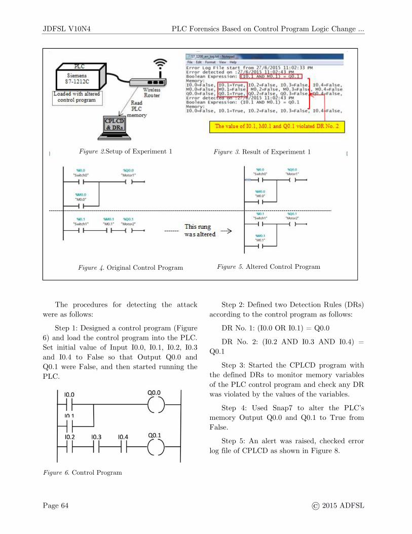
Experiment 1: Setup andprocedures for detecting Control
Program AttackTo set up this experiment, we used one PLC,one PC and a router. They were connected asdiagram shown in Figure 2. The PC wasinstalled with CPLCD for detecting the attack.
The procedures for detecting the attackwere as follows:
Step 1: Designed two control programs.One was the original program in Figure 4 andthe other one was altered by an attacker inFigure 5 to create abnormal instructions. Theattacker altered the second rung of the originalcontrol program from (I0.1 AND M0.1) = Q0.1to (I0.1 OR M0.1) = Q0.1
Step 2: Defined two Detection Rules (DRs)based on the original control program asfollows:
DR No. 1: (I0.0 OR M0.0) = Q0.0DR No. 2: (I0.1 AND M0.1) = Q0.1Step 3: Loaded the altered control program
with initial memory values, M0.1=False and
Input I0.1=True into the Siemens Simatic S7-1200 PLC by Siemens programming softwareSTEP 7 and started running the PLC.
Step 4: Started the CPLCD program withthe defined DRs to monitor memory variablesof the control program in the PLC and checkany DR was violated by the values of thevariables.
Step 5: An alert was raised, checked errorlog file of CPLCD as shown in Figure 3.
Experiment 1: ResultAccording to the error log captured by CPLCDin Figure 3, an alert was raised and logged on27/6/2015, 11:02:43 PM because the values ofI0.1, M0.1 and Q0.1 violated DR No. 2. Undernormal operation of DR No. 2, Q0.1=Trueonly if both I0.1 and M0.1=True at the sametime, otherwise, Q0.1=False. However,CPLCD detected that I0.1=True, M0.1=Falseand Q0.1=False which violated DR No. 2.
Experiment 2: Setup andprocedures for detecting
Memory Read and Write LogicAttack
This experiment setup was same asExperiment 1 but one more PC was added asshown in Figure 7. The PC installed withSnap7 acting as an Attacker to performMemory Read and Write Logic Attack. Weused Snap7 to alter the PLC’s memory data.Snap7 is not a PLC attacking tool, it is anopen source, 32/64 bit, multi-platformEthernet communication suite for interfacingnatively with Siemens S7 PLCs [7].
JDFSL V10N4 PLC Forensics Based on Control Program Logic Change …
Page 64 © 2015 ADFSL
The procedures for detecting the attackwere as follows:
Step 1: Designed a control program (Figure6) and load the control program into the PLC.Set initial value of Input I0.0, I0.1, I0.2, I0.3and I0.4 to False so that Output Q0.0 andQ0.1 were False, and then started running thePLC.
Figure 6. Control Program
Step 2: Defined two Detection Rules (DRs)according to the control program as follows:
DR No. 1: (I0.0 OR I0.1) = Q0.0DR No. 2: (I0.2 AND I0.3 AND I0.4) =
Q0.1Step 3: Started the CPLCD program with
the defined DRs to monitor memory variablesof the PLC control program and check any DRwas violated by the values of the variables.
Step 4: Used Snap7 to alter the PLC’smemory Output Q0.0 and Q0.1 to True fromFalse.
Step 5: An alert was raised, checked errorlog file of CPLCD as shown in Figure 8.
Figure 2.Setup of Experiment 1
Figure 4. Original Control Program Figure 5. Altered Control Program
Figure 3. Result of Experiment 1

PLC Forensics Based on Control Program Logic Change … JDFSL V10N4
© 2015 ADFSL Page 65
Experiment 2: ResultAccording to the error log captured by CPLCDin Figure 8, DR No. 1 and DR No. 2 wereviolated on 28/6/2015 9:07:40 AM because ofthe action in Step 4. DR No. 1 was violated bythe value Q0.0=True and DR No. 2 wasviolated by the value Q0.1=True.
DISCUSSIONBased on the defined Detection Rules (DRs),Control Program Logic Change Detector(CPLCD) was able to detect the ControlProgram Attack and Memory Read and WriteLogic Attack. However, it is difficult orimpossible to define the entire DRs from acomplicated LAD diagram which has a lot ofrungs and to monitor all the memory variables.To address this issue, we propose to selectimportant rungs for monitoring instead of allthe rungs. Different control systems havedifferent important rules. In general, a rungused to stop control system under dangerouscondition should be important.
CPLCD can detect Memory Read andWrite Logic Attack, however, it cannot
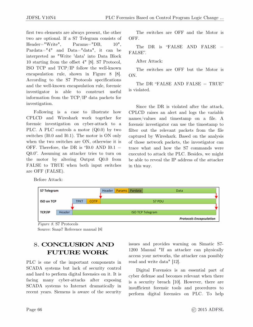
provide sufficient information for forensicinvestigation. CPLCD does not captureinformation about how and who changes thePLC memory which induced the abnormalPLC operations. In order to supplement moreinformation for forensic investigation, werecommend CPLCD to work with networkpacket analyzer Wireshark. Wiresharksupports PROFINET to record and analyzethe Ethernet message frames. It can be used todissect the ISO on TCP-packets forcommunication to Siemens S7 PLCs afteradding Wireshark dissector plugin for S7communication.
S7 Protocol is Function oriented orCommand oriented, i.e. each transmissioncontains a command or a reply. It is thebackbone of the Siemens communications, itsEthernet implementation relies on ISO-on-TCP(RFC1006) which is Block oriented by design[8]. Each block is named S7 PDU (ProtocolData Unit). Each command (S7 Telegram)consists of a header, a set of parameters(Params), a parameters data (Pardata) and adata block (Data) as shown in Figure 8. The
Figure 7. Setup of Experiment 2 Figure 8. Result of Experiment 2
JDFSL V10N4 PLC Forensics Based on Control Program Logic Change …
Page 66 © 2015 ADFSL
first two elements are always present, the othertwo are optional. If a S7 Telegram consists ofHeader="Write", Params="DB, 10",Pardata="4" and Data="data", it can beinterpreted as "Write 'data' into Data Block10 starting from the offset 4" [8]. S7 Protocol,ISO TCP and TCP/IP follow the well-knownencapsulation rule, shown in Figure 8 [8].According to the S7 Protocols specificationsand the well-known encapsulation rule, forensicinvestigator is able to construct usefulinformation from the TCP/IP data packets forinvestigation.
Following is a case to illustrate howCPLCD and Wireshark work together forforensic investigation on cyber-attack to aPLC. A PLC controls a motor (Q0.0) by twoswitches (I0.0 and I0.1). The motor is ON onlywhen the two switches are ON, otherwise it isOFF. Therefore, the DR is “I0.0 AND I0.1 =Q0.0”. Assuming an attacker tries to turn onthe motor by altering Output Q0.0 fromFALSE to TRUE when both input switchesare OFF (FALSE).
Before Attack:
The switches are OFF and the Motor isOFF.
The DR is “FALSE AND FALSE =FALSE”.
After Attack:The switches are OFF but the Motor is
ON.The DR “FALSE AND FALSE = TRUE”
is violated.
Since the DR is violated after the attack,CPLCD raises an alert and logs the variablenames/values and timestamp on a file. Aforensic investigator can use the timestamp tofilter out the relevant packets from the filecaptured by Wireshark. Based on the analysisof those network packets, the investigator cantrace what and how the S7 commands wereexecuted to attack the PLC. Besides, we mightbe able to reveal the IP address of the attackerin this way.
CONCLUSION ANDFUTURE WORK
PLC is one of the important components inSCADA systems but lack of security controland hard to perform digital forensics on it. It isfacing many cyber-attacks after exposingSCADA systems to Internet dramatically inrecent years. Siemens is aware of the security
issues and provides warning on Simatic S7-1200 Manual "If an attacker can physicallyaccess your networks, the attacker can possiblyread and write data" [12].
Digital Forensics is an essential part ofcyber defense and becomes relevant when thereis a security breach [10]. However, there areinsufficient forensic tools and procedures toperform digital forensics on PLC. To help
Figure 8. S7 ProtocolsSource: Snap7 Reference manual [8]
Figure 3 S7 ProtocolsSource: Snap7 Reference manual [8]
PLC Forensics Based on Control Program Logic Change … JDFSL V10N4
© 2015 ADFSL Page 67
overcome challenges on PLC protection andforensic investigation, in this paper, weintroduced how Control Program LogicChange Detector (CPLCD) and DetectionRules (DRs) can be used to detect ControlProgram Attack and Memory Read and WriteLogic Attack. In addition, we illustrated howCPLCD work with Wireshark dissector for S7communication to perform forensicinvestigation on S7 PLCs.
In future, we will apply CPLCD to varioustypes and brands of PLCs for testing ofperformance, accuracy and feasibility.Furthermore, we will expand our testing to asimulated control system application such aselevator, traffic light, robotic arm, etc.

JDFSL V10N4 PLC Forensics Based on Control Program Logic Change …
Page 68 © 2015 ADFSL
REFERENCESW. Bolton, Programmable Logic Controllers
(4th Edition)Irfan Ahmed, Sebastian Obermeier and Martin
Naedele, Golen G. Richard III: SCADASystem: Challenges for ForensicsInvestigations, IEEE Computer, Vol. 45No. 12, December 2012, pp 44–51, USA.
Dillon Beresford, Exploiting Siemens SimaticS7 PLCs, Black Hat USA+2011, July 8,2011
Alex Sentcha, LibNoDave – exchange datawith Siemens PLC,https://alexsentcha.wordpress.com/ Lastaccessed on 31 May 2015
R.M. van der Knijff, Control systems/SCADAforensics, what's the difference?, DigitalInvestigation 11 (2014)
Nicolas Falliere, Liam O Murchu, and EricChien: W32.Stuxnet Dossier, Version 1.4,Symantec Corporation, February 2011
Davide Nardella, Snap7http://snap7.sourceforge.net/ Last accessedon 13, June 2015
Davide Nardella, Snap7 Reference manualRev.5, January 1, 2015
PROFINET, Wikipediahttp://en.wikipedia.org/wiki/PROFINET_IO, Last accessed on 18 June 2015
K. Mandia, C. Prosise and M. Pepe, “IncidentResponse and Computer Forensics”,McGraw-Hill/Osborne, Emeryville,California, 2003
Fabro, M: Recommended Practice: CreatingCyber Forensic Plan for Control Systems,Department of Homeland Security (2008),Idaho National Laboratory (INL), August2008, USA
SIEMENS SIMATIC S7-1200 Easy BookManual 01/2015