plc designer v3 - lenzedownload.lenze.com/akb/german/201400199/sw_applicationtemplat… ·...
TRANSCRIPT
L
Ä.OJ_ä
1346
4162
PLC Designer
Engineering tools
Application Template PackML _ _ _ _ _ _ _ _ _ Software manual EN
2 Lenze · ApplicationTemplate PackML · 1.0 EN - 05/2014
_ _ _ _ _ _ _ _ _ _ _ _ _ _ _ _ _ _ _ _ _ _ _ _ _ _ _ _ _ _ _ _ _ _ _ _ _ _ _ _ _ _ _ _ _ _ _ _ _ _ _ _ _ _ _ _ _ _ _ _ _ _ _ _
1 About this documentation _ _ _ _ _ _ _ _ _ _ _ _ _ _ _ _ _ _ _ _ _ _ _ _ _ _ _ _ _ _ _ _ _ _ _ _ _ _ _ 41.1 Document history _ _ _ _ _ _ _ _ _ _ _ _ _ _ _ _ _ _ _ _ _ _ _ _ _ _ _ _ _ _ _ _ _ _ _ _ _ _ _ _ _ _ _ _ 61.2 Conventions used _ _ _ _ _ _ _ _ _ _ _ _ _ _ _ _ _ _ _ _ _ _ _ _ _ _ _ _ _ _ _ _ _ _ _ _ _ _ _ _ _ _ _ _ 71.3 Notes used _ _ _ _ _ _ _ _ _ _ _ _ _ _ _ _ _ _ _ _ _ _ _ _ _ _ _ _ _ _ _ _ _ _ _ _ _ _ _ _ _ _ _ _ _ _ _ _ 81.4 Terminology used (presented according to the order in the device view) _ _ _ _ _ _ _ _ _ _ _ _ _ _ 9
2 Safety instructions _ _ _ _ _ _ _ _ _ _ _ _ _ _ _ _ _ _ _ _ _ _ _ _ _ _ _ _ _ _ _ _ _ _ _ _ _ _ _ _ _ _ _ _ 10
3 Preconditions _ _ _ _ _ _ _ _ _ _ _ _ _ _ _ _ _ _ _ _ _ _ _ _ _ _ _ _ _ _ _ _ _ _ _ _ _ _ _ _ _ _ _ _ _ _ 113.1 System requirements _ _ _ _ _ _ _ _ _ _ _ _ _ _ _ _ _ _ _ _ _ _ _ _ _ _ _ _ _ _ _ _ _ _ _ _ _ _ _ _ _ _ 113.2 Setting up communication to the Controller _ _ _ _ _ _ _ _ _ _ _ _ _ _ _ _ _ _ _ _ _ _ _ _ _ _ _ _ _ 11
4 What is the ApplicationTemplate PackML? _ _ _ _ _ _ _ _ _ _ _ _ _ _ _ _ _ _ _ _ _ _ _ _ _ _ _ _ _ _ 134.1 Targets of the ApplicationTemplate PackML _ _ _ _ _ _ _ _ _ _ _ _ _ _ _ _ _ _ _ _ _ _ _ _ _ _ _ _ _ _ 134.2 Features of the Application Sample PackML at a glance _ _ _ _ _ _ _ _ _ _ _ _ _ _ _ _ _ _ _ _ _ _ _ 144.3 Elements of the ApplicationTemplate PackML _ _ _ _ _ _ _ _ _ _ _ _ _ _ _ _ _ _ _ _ _ _ _ _ _ _ _ _ _ 15
4.3.1 Machine Module Tree - MMT _ _ _ _ _ _ _ _ _ _ _ _ _ _ _ _ _ _ _ _ _ _ _ _ _ _ _ _ _ _ _ _ _ 154.3.2 Machine modules (MM) _ _ _ _ _ _ _ _ _ _ _ _ _ _ _ _ _ _ _ _ _ _ _ _ _ _ _ _ _ _ _ _ _ _ _ _ 164.3.3 Addressing the machine modules _ _ _ _ _ _ _ _ _ _ _ _ _ _ _ _ _ _ _ _ _ _ _ _ _ _ _ _ _ _ _ 174.3.4 Module application (MAP) _ _ _ _ _ _ _ _ _ _ _ _ _ _ _ _ _ _ _ _ _ _ _ _ _ _ _ _ _ _ _ _ _ _ _ 174.3.5 Modes: Machine operating modes _ _ _ _ _ _ _ _ _ _ _ _ _ _ _ _ _ _ _ _ _ _ _ _ _ _ _ _ _ _ 184.3.6 Communication between the machine modules _ _ _ _ _ _ _ _ _ _ _ _ _ _ _ _ _ _ _ _ _ _ 18
4.3.6.1 Predefined operating modes in ModApp1 _ _ _ _ _ _ _ _ _ _ _ _ _ _ _ _ _ _ _ _ 204.3.6.2 Creating own modes _ _ _ _ _ _ _ _ _ _ _ _ _ _ _ _ _ _ _ _ _ _ _ _ _ _ _ _ _ _ _ 21
4.3.7 State machine _ _ _ _ _ _ _ _ _ _ _ _ _ _ _ _ _ _ _ _ _ _ _ _ _ _ _ _ _ _ _ _ _ _ _ _ _ _ _ _ _ 234.3.7.1 State transitions - overview _ _ _ _ _ _ _ _ _ _ _ _ _ _ _ _ _ _ _ _ _ _ _ _ _ _ _ _ 234.3.7.2 Methods for changing over the states _ _ _ _ _ _ _ _ _ _ _ _ _ _ _ _ _ _ _ _ _ _ 24
4.3.8 Alarmhandling (error handling) _ _ _ _ _ _ _ _ _ _ _ _ _ _ _ _ _ _ _ _ _ _ _ _ _ _ _ _ _ _ _ _ 24
5 Structuring the automation system: Standard procedure _ _ _ _ _ _ _ _ _ _ _ _ _ _ _ _ _ _ _ _ _ _ 255.1 Assign the relative address to the machine modules. _ _ _ _ _ _ _ _ _ _ _ _ _ _ _ _ _ _ _ _ _ _ _ _ _ 275.2 Structuring within a machine module: Assigning MAP subfunction to the tasks _ _ _ _ _ _ _ _ _ _ 28
6 Overview - the folder structure in the ApplicationTemplate PackML _ _ _ _ _ _ _ _ _ _ _ _ _ _ _ _ 30
7 Opening the ApplicationTemplate PackML _ _ _ _ _ _ _ _ _ _ _ _ _ _ _ _ _ _ _ _ _ _ _ _ _ _ _ _ _ _ 317.1 Create a new project - open the ApplicationTemplate PackML _ _ _ _ _ _ _ _ _ _ _ _ _ _ _ _ _ _ _ _ 327.2 Updating the controller in the project (optional) _ _ _ _ _ _ _ _ _ _ _ _ _ _ _ _ _ _ _ _ _ _ _ _ _ _ _ 337.3 Going online _ _ _ _ _ _ _ _ _ _ _ _ _ _ _ _ _ _ _ _ _ _ _ _ _ _ _ _ _ _ _ _ _ _ _ _ _ _ _ _ _ _ _ _ _ _ _ 33
7.3.1 Compiling the project data _ _ _ _ _ _ _ _ _ _ _ _ _ _ _ _ _ _ _ _ _ _ _ _ _ _ _ _ _ _ _ _ _ _ 337.3.2 Transferring the project to the control - "Log in" _ _ _ _ _ _ _ _ _ _ _ _ _ _ _ _ _ _ _ _ _ _ 33
7.4 Downloading and starting the PLC program _ _ _ _ _ _ _ _ _ _ _ _ _ _ _ _ _ _ _ _ _ _ _ _ _ _ _ _ _ _ 337.5 Getting started - operating the ApplicationTemplate PackML _ _ _ _ _ _ _ _ _ _ _ _ _ _ _ _ _ _ _ _ 347.6 Visualisation of the machine modules _ _ _ _ _ _ _ _ _ _ _ _ _ _ _ _ _ _ _ _ _ _ _ _ _ _ _ _ _ _ _ _ _ 35
8 Working with the ApplicationTemplate PackML _ _ _ _ _ _ _ _ _ _ _ _ _ _ _ _ _ _ _ _ _ _ _ _ _ _ _ 368.1 Mapping the actual machine structure: Add devices _ _ _ _ _ _ _ _ _ _ _ _ _ _ _ _ _ _ _ _ _ _ _ _ _ 378.2 Creating machine modules: Copy/insert machine module templates _ _ _ _ _ _ _ _ _ _ _ _ _ _ _ _ 408.3 Integrating machine modules in the MMT _ _ _ _ _ _ _ _ _ _ _ _ _ _ _ _ _ _ _ _ _ _ _ _ _ _ _ _ _ _ _ 418.4 Assigning the module application (ModApp) to the task _ _ _ _ _ _ _ _ _ _ _ _ _ _ _ _ _ _ _ _ _ _ _ 428.5 Create MM Instance: Creating instances of a machine module _ _ _ _ _ _ _ _ _ _ _ _ _ _ _ _ _ _ _ 448.6 Delete Machine Module: Remove instances of a machine module _ _ _ _ _ _ _ _ _ _ _ _ _ _ _ _ _ _ 458.7 Removing machine modules _ _ _ _ _ _ _ _ _ _ _ _ _ _ _ _ _ _ _ _ _ _ _ _ _ _ _ _ _ _ _ _ _ _ _ _ _ _ 468.8 Module ID _ _ _ _ _ _ _ _ _ _ _ _ _ _ _ _ _ _ _ _ _ _ _ _ _ _ _ _ _ _ _ _ _ _ _ _ _ _ _ _ _ _ _ _ _ _ _ _ 468.9 Inserting an axis _ _ _ _ _ _ _ _ _ _ _ _ _ _ _ _ _ _ _ _ _ _ _ _ _ _ _ _ _ _ _ _ _ _ _ _ _ _ _ _ _ _ _ _ _ 48
Contents
Lenze · ApplicationTemplate PackML · 1.0 EN - 05/2014 3
Contents
_ _ _ _ _ _ _ _ _ _ _ _ _ _ _ _ _ _ _ _ _ _ _ _ _ _ _ _ _ _ _ _ _ _ _ _ _ _ _ _ _ _ _ _ _ _ _ _ _ _ _ _ _ _ _ _ _ _ _ _ _ _ _ _
8.10 Integrating I/O modules of the I/O system 1000 with a machine module _ _ _ _ _ _ _ _ _ _ _ _ _ _ 508.11 Creating module applications _ _ _ _ _ _ _ _ _ _ _ _ _ _ _ _ _ _ _ _ _ _ _ _ _ _ _ _ _ _ _ _ _ _ _ _ _ _ 52
8.11.1 Programming with the module application _ _ _ _ _ _ _ _ _ _ _ _ _ _ _ _ _ _ _ _ _ _ _ _ _ 538.11.2 Integrating a module application _ _ _ _ _ _ _ _ _ _ _ _ _ _ _ _ _ _ _ _ _ _ _ _ _ _ _ _ _ _ _ 54
9 Architecture: The ApplicationTemplate PackML in detail _ _ _ _ _ _ _ _ _ _ _ _ _ _ _ _ _ _ _ _ _ _ _ 579.1 Accessing structure variables of machine modules _ _ _ _ _ _ _ _ _ _ _ _ _ _ _ _ _ _ _ _ _ _ _ _ _ _ 57
9.1.1 Accessing module's intrinsic structure variables _ _ _ _ _ _ _ _ _ _ _ _ _ _ _ _ _ _ _ _ _ _ _ 579.1.2 User Tags: Defining own data elements _ _ _ _ _ _ _ _ _ _ _ _ _ _ _ _ _ _ _ _ _ _ _ _ _ _ _ 589.1.3 Accessing structures of other machine modules _ _ _ _ _ _ _ _ _ _ _ _ _ _ _ _ _ _ _ _ _ _ _ 59
9.2 The AppChannelData structure(ACD) _ _ _ _ _ _ _ _ _ _ _ _ _ _ _ _ _ _ _ _ _ _ _ _ _ _ _ _ _ _ _ _ _ 599.2.1 Declaring/recording the ACD structure in the MFB _ _ _ _ _ _ _ _ _ _ _ _ _ _ _ _ _ _ _ _ _ 609.2.2 Accessing the ACD structure of the master module - by means of the MFB module application 609.2.3 Accessing the ACD structure of the slave modules - by means of the modes of the master module
619.2.4 The structure MachineModuleData (MMD) _ _ _ _ _ _ _ _ _ _ _ _ _ _ _ _ _ _ _ _ _ _ _ _ _ 63
9.3 State machine in detail _ _ _ _ _ _ _ _ _ _ _ _ _ _ _ _ _ _ _ _ _ _ _ _ _ _ _ _ _ _ _ _ _ _ _ _ _ _ _ _ _ 649.3.1 State transitions and conditions - overview _ _ _ _ _ _ _ _ _ _ _ _ _ _ _ _ _ _ _ _ _ _ _ _ _ 649.3.2 Methods for changing over the state transitions _ _ _ _ _ _ _ _ _ _ _ _ _ _ _ _ _ _ _ _ _ _ 659.3.3 The state transitions in detail: Command_CtrlCmds() method _ _ _ _ _ _ _ _ _ _ _ _ _ _ _ 679.3.4 Possible states in detail _ _ _ _ _ _ _ _ _ _ _ _ _ _ _ _ _ _ _ _ _ _ _ _ _ _ _ _ _ _ _ _ _ _ _ _ 68
9.4 Standard coupling of the machine modules _ _ _ _ _ _ _ _ _ _ _ _ _ _ _ _ _ _ _ _ _ _ _ _ _ _ _ _ _ _ 709.4.1 Predefined standard mechanism of the state machine _ _ _ _ _ _ _ _ _ _ _ _ _ _ _ _ _ _ _ 70
9.4.1.1 The Command_DisableModule method: Decoupling modules _ _ _ _ _ _ _ _ _ 719.4.1.2 Renewed coupling of machine modules _ _ _ _ _ _ _ _ _ _ _ _ _ _ _ _ _ _ _ _ _ 71
9.5 Influencing state transitions _ _ _ _ _ _ _ _ _ _ _ _ _ _ _ _ _ _ _ _ _ _ _ _ _ _ _ _ _ _ _ _ _ _ _ _ _ _ 719.6 Stater machine: Query examples _ _ _ _ _ _ _ _ _ _ _ _ _ _ _ _ _ _ _ _ _ _ _ _ _ _ _ _ _ _ _ _ _ _ _ _ 729.7 Where can the response of a machine module be programmed? _ _ _ _ _ _ _ _ _ _ _ _ _ _ _ _ _ _ 74
9.7.1 State transition (state entry/state exit) _ _ _ _ _ _ _ _ _ _ _ _ _ _ _ _ _ _ _ _ _ _ _ _ _ _ _ 749.8 Alarm handling (error handling) _ _ _ _ _ _ _ _ _ _ _ _ _ _ _ _ _ _ _ _ _ _ _ _ _ _ _ _ _ _ _ _ _ _ _ _ 75
9.8.1 Defining alarms _ _ _ _ _ _ _ _ _ _ _ _ _ _ _ _ _ _ _ _ _ _ _ _ _ _ _ _ _ _ _ _ _ _ _ _ _ _ _ _ 759.8.2 Acknowledging alarms _ _ _ _ _ _ _ _ _ _ _ _ _ _ _ _ _ _ _ _ _ _ _ _ _ _ _ _ _ _ _ _ _ _ _ _ 769.8.3 Acknowledging alarms: Response in the machine module _ _ _ _ _ _ _ _ _ _ _ _ _ _ _ _ _ 76
9.9 Triggering alarms _ _ _ _ _ _ _ _ _ _ _ _ _ _ _ _ _ _ _ _ _ _ _ _ _ _ _ _ _ _ _ _ _ _ _ _ _ _ _ _ _ _ _ _ 789.10 Central management of alarms _ _ _ _ _ _ _ _ _ _ _ _ _ _ _ _ _ _ _ _ _ _ _ _ _ _ _ _ _ _ _ _ _ _ _ _ 799.11 The alarm information block _ _ _ _ _ _ _ _ _ _ _ _ _ _ _ _ _ _ _ _ _ _ _ _ _ _ _ _ _ _ _ _ _ _ _ _ _ _ 809.12 Export overview of the alarms of all machine modules: CSV file _ _ _ _ _ _ _ _ _ _ _ _ _ _ _ _ _ _ _ 809.13 Logbook _ _ _ _ _ _ _ _ _ _ _ _ _ _ _ _ _ _ _ _ _ _ _ _ _ _ _ _ _ _ _ _ _ _ _ _ _ _ _ _ _ _ _ _ _ _ _ _ _ 819.14 Module diagnostics _ _ _ _ _ _ _ _ _ _ _ _ _ _ _ _ _ _ _ _ _ _ _ _ _ _ _ _ _ _ _ _ _ _ _ _ _ _ _ _ _ _ _ 829.15 Multitasking _ _ _ _ _ _ _ _ _ _ _ _ _ _ _ _ _ _ _ _ _ _ _ _ _ _ _ _ _ _ _ _ _ _ _ _ _ _ _ _ _ _ _ _ _ _ _ 829.16 Consistent data transfer _ _ _ _ _ _ _ _ _ _ _ _ _ _ _ _ _ _ _ _ _ _ _ _ _ _ _ _ _ _ _ _ _ _ _ _ _ _ _ _ 83
10 Visualising in the ApplicationTemplate PackML _ _ _ _ _ _ _ _ _ _ _ _ _ _ _ _ _ _ _ _ _ _ _ _ _ _ _ _ 8610.1 Extending the visualization _ _ _ _ _ _ _ _ _ _ _ _ _ _ _ _ _ _ _ _ _ _ _ _ _ _ _ _ _ _ _ _ _ _ _ _ _ _ _ 8610.2 Defining the properties of buttons _ _ _ _ _ _ _ _ _ _ _ _ _ _ _ _ _ _ _ _ _ _ _ _ _ _ _ _ _ _ _ _ _ _ _ 8810.3 Adding a visualization: Standard procedure _ _ _ _ _ _ _ _ _ _ _ _ _ _ _ _ _ _ _ _ _ _ _ _ _ _ _ _ _ _ 89
11 An overview of the methods _ _ _ _ _ _ _ _ _ _ _ _ _ _ _ _ _ _ _ _ _ _ _ _ _ _ _ _ _ _ _ _ _ _ _ _ _ _ 9111.1 An overview of the admin methods : Admin_xxx _ _ _ _ _ _ _ _ _ _ _ _ _ _ _ _ _ _ _ _ _ _ _ _ _ _ _ 9111.2 An overview of the command methods: Command_xxx _ _ _ _ _ _ _ _ _ _ _ _ _ _ _ _ _ _ _ _ _ _ _ 9211.3 An overview of the status methods: Status_xxx _ _ _ _ _ _ _ _ _ _ _ _ _ _ _ _ _ _ _ _ _ _ _ _ _ _ _ 94
Your opinion is important to us _ _ _ _ _ _ _ _ _ _ _ _ _ _ _ _ _ _ _ _ _ _ _ _ _ _ _ _ _ _ _ _ _ _ _ _ _ 98

About this documentation
4 Lenze · ApplicationTemplate PackML · 1.0 EN - 05/2014
_ _ _ _ _ _ _ _ _ _ _ _ _ _ _ _ _ _ _ _ _ _ _ _ _ _ _ _ _ _ _ _ _ _ _ _ _ _ _ _ _ _ _ _ _ _ _ _ _ _ _ _ _ _ _ _ _ _ _ _ _ _ _ _
1 About this documentation
This documentation describes the operating mode of the Lenze "ApplicationTemplate PackML"which serves as a basis for programming a Lenze automation system. The used "Controller-basedautomation" system consists of a Lenze Controller and drive components which are connected viathe bus system.
Tip!
Information and tools regarding the Lenze products can be found in the download area at:http://www.Lenze.com
This manual is part of the "Controller-based Automation" manual collection. The manual collectionconsists of the documents:
Note!
This documentation is a supplement to the »PLC Designer« online help.
Type of documentation Subject
System manuals System overview/example topologies• Controller-based Automation• Visualisation
Communication manuals Bus systems• Controller-based Automation EtherCAT®• Controller-based Automation CANopen®• Controller-based Automation PROFIBUS®• Controller-based Automation PROFINET®
Online helps/software manuals
Lenze Engineering tools• »PLC Designer«: Programming• »Engineer«: Configuration of controllers• »VisiWinNET® Smart«: Visualisation• »Backup & Restore«: Backing up/restoring data

Lenze · ApplicationTemplate PackML · 1.0 EN - 05/2014 5
About this documentation
_ _ _ _ _ _ _ _ _ _ _ _ _ _ _ _ _ _ _ _ _ _ _ _ _ _ _ _ _ _ _ _ _ _ _ _ _ _ _ _ _ _ _ _ _ _ _ _ _ _ _ _ _ _ _ _ _ _ _ _ _ _ _ _
Further technical documentation on Lenze products
Further information on Lenze products which can be used in connection with Controller-basedAutomation can be found in the following documentation:
Target group
This documentation addresses to all persons who plan, commission, and program a Lenzeautomation system on the basis of the Lenze "ApplicationTemplate PackML" as part of the"Controller-based Automation".
Screenshots/application examples
All screenshots in this documentation are application examples. Depending on the firmwareversion of the Lenze devices and the software version of the engineering tools installed (»PLCDesigner«), the screenshots in this documentation may deviate from the screen representation.
Mounting & wiring Icons
Mounting instructions• Controller• Communication cards (MC-xxx)• I/O system 1000 (EPM-Sxxx)• Inverter• Communication modules
Printed documentationOnline help in the Lenze Engineering tool/software manuals and communication manuals are provided as PDF files on the Internet.
Using sample applications/an application template
Online help/software manuals• i700 Application Sample• Application Samples• ApplicationTemplate• ApplicationTemplate PackML
Parameterisation, configuration, commissioning
Online help/software manuals• Controller• i700 servo inverter• Servo Drive 9400 HighLine/PLC/
regenerative power supply module• Inverter Drive 8400 StateLine/HighLine/TopLine• 1000 I/O system (EPM-Sxxx)
Online help/communication manuals• Bus systems• Communication modules
About this documentationDocument history
6 Lenze · ApplicationTemplate PackML · 1.0 EN - 05/2014
_ _ _ _ _ _ _ _ _ _ _ _ _ _ _ _ _ _ _ _ _ _ _ _ _ _ _ _ _ _ _ _ _ _ _ _ _ _ _ _ _ _ _ _ _ _ _ _ _ _ _ _ _ _ _ _ _ _ _ _ _ _ _ _
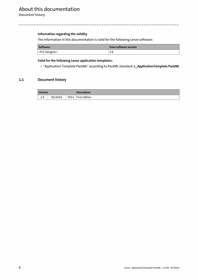
Information regarding the validity
The information in this documentation is valid for the following Lenze software:
Valid for the following Lenze application templates:
• "Application Template PackML" according to PackML standard: L_ApplicationTemplate PackML
1.1 Document history
Software from software version
»PLC Designer« 3.8
Version Description
1.0 05/2014 TD11 First edition
Lenze · ApplicationTemplate PackML · 1.0 EN - 05/2014 7
About this documentationConventions used
_ _ _ _ _ _ _ _ _ _ _ _ _ _ _ _ _ _ _ _ _ _ _ _ _ _ _ _ _ _ _ _ _ _ _ _ _ _ _ _ _ _ _ _ _ _ _ _ _ _ _ _ _ _ _ _ _ _ _ _ _ _ _ _
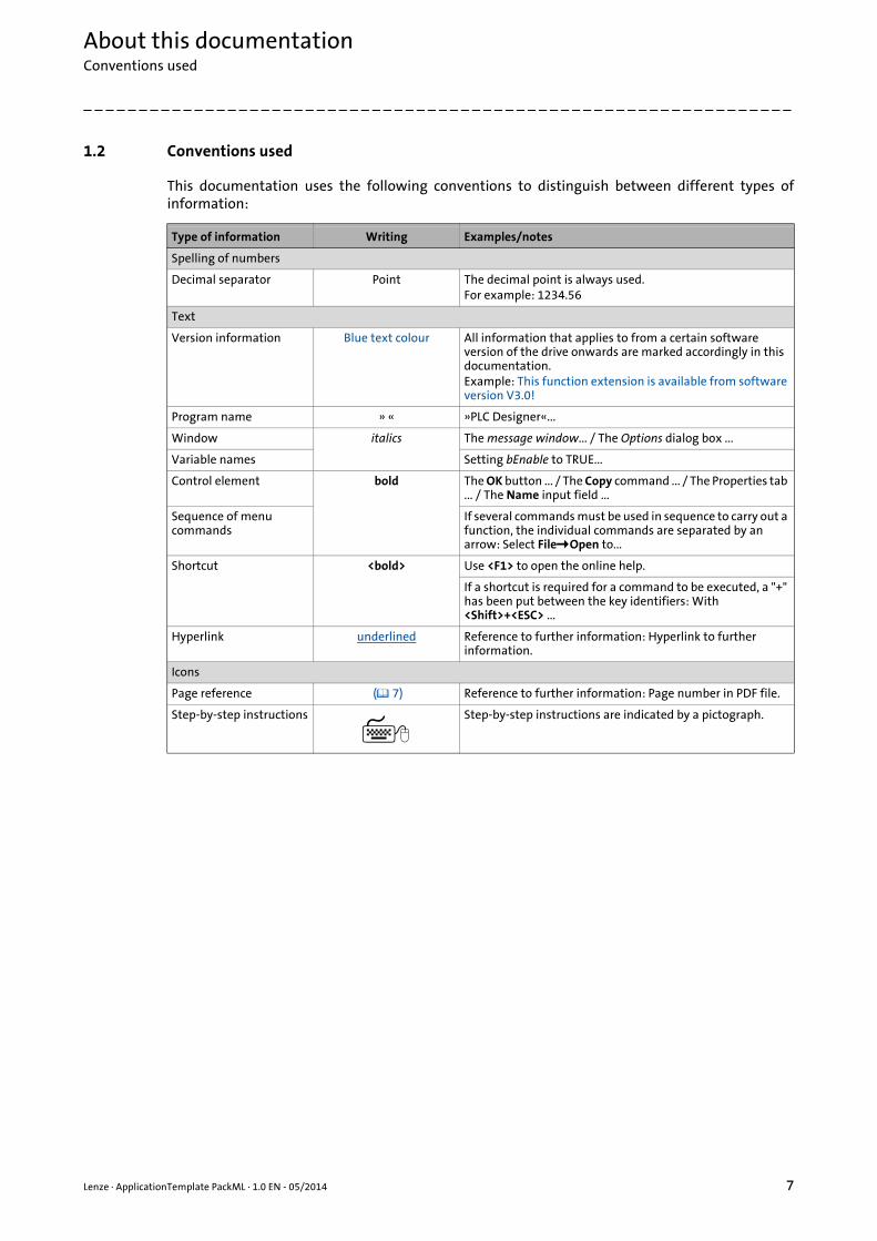
1.2 Conventions used
This documentation uses the following conventions to distinguish between different types ofinformation:
Type of information Writing Examples/notes
Spelling of numbers
Decimal separator Point The decimal point is always used.For example: 1234.56
Text
Version information Blue text colour All information that applies to from a certain software version of the drive onwards are marked accordingly in this documentation.Example: This function extension is available from software version V3.0!
Program name » « »PLC Designer«...
Window italics The message window... / The Options dialog box ...
Variable names Setting bEnable to TRUE...
Control element bold The OK button ... / The Copy command ... / The Properties tab ... / The Name input field ...
Sequence of menu commands
If several commands must be used in sequence to carry out a function, the individual commands are separated by an arrow: Select FileOpen to...
Shortcut <bold> Use <F1> to open the online help.
If a shortcut is required for a command to be executed, a "+" has been put between the key identifiers: With <Shift>+<ESC> ...
Hyperlink underlined Reference to further information: Hyperlink to further information.
Icons
Page reference ( 7) Reference to further information: Page number in PDF file.
Step-by-step instructions Step-by-step instructions are indicated by a pictograph.
About this documentationNotes used
8 Lenze · ApplicationTemplate PackML · 1.0 EN - 05/2014
_ _ _ _ _ _ _ _ _ _ _ _ _ _ _ _ _ _ _ _ _ _ _ _ _ _ _ _ _ _ _ _ _ _ _ _ _ _ _ _ _ _ _ _ _ _ _ _ _ _ _ _ _ _ _ _ _ _ _ _ _ _ _ _
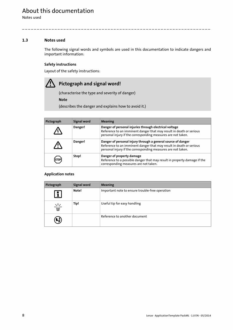
1.3 Notes used
The following signal words and symbols are used in this documentation to indicate dangers andimportant information:
Safety instructions
Layout of the safety instructions:
Application notes
Pictograph and signal word!
(characterise the type and severity of danger)
Note
(describes the danger and explains how to avoid it.)
Pictograph Signal word Meaning
Danger! Danger of personal injuries through electrical voltageReference to an imminent danger that may result in death or serious personal injury if the corresponding measures are not taken.
Danger! Danger of personal injury through a general source of dangerReference to an imminent danger that may result in death or serious personal injury if the corresponding measures are not taken.
Stop! Danger of property damageReference to a possible danger that may result in property damage if the corresponding measures are not taken.
Pictograph Signal word Meaning
Note! Important note to ensure trouble-free operation
Tip! Useful tip for easy handling
Reference to another document
Lenze · ApplicationTemplate PackML · 1.0 EN - 05/2014 9
About this documentationTerminology used (presented according to the order in the device view)
_ _ _ _ _ _ _ _ _ _ _ _ _ _ _ _ _ _ _ _ _ _ _ _ _ _ _ _ _ _ _ _ _ _ _ _ _ _ _ _ _ _ _ _ _ _ _ _ _ _ _ _ _ _ _ _ _ _ _ _ _ _ _ _
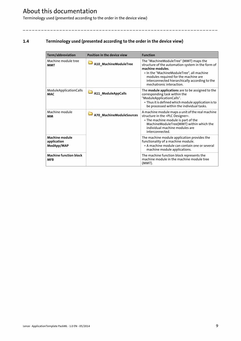
1.4 Terminology used (presented according to the order in the device view)
Term/abbreviation Position in the device view Function
Machine module treeMMT A10_MachineModuleTree
The "MachineModuleTree" (MMT) maps the structure of the automation system in the form of machine modules.
• In the "MachineModuleTree", all machine modules required for the machine are interconnected hierarchically according to the mechatronic interaction.
ModuleApplicationCalls MAC A11_ModuleAppCalls
The module applications are to be assigned to the corresponding task within the "ModuleApplicationCalls".
• Thus it is defined which module application is to be processed within the individual tasks.
Machine moduleMM A70_MachineModuleSources
A machine module maps a unit of the real machine structure in the »PLC Designer«.
• The machine module is part of the MachineModuleTree(MMT) within which the individual machine modules are interconnected.
Machine module applicationModApp/MAP
The machine module application provides the functionality of a machine module.
• A machine module can contain one or several machine module applications.
Machine function blockMFB
The machine function block represents the machine module in the machine module tree (MMT).

Safety instructions
10 Lenze · ApplicationTemplate PackML · 1.0 EN - 05/2014
_ _ _ _ _ _ _ _ _ _ _ _ _ _ _ _ _ _ _ _ _ _ _ _ _ _ _ _ _ _ _ _ _ _ _ _ _ _ _ _ _ _ _ _ _ _ _ _ _ _ _ _ _ _ _ _ _ _ _ _ _ _ _ _
2 Safety instructions
Please observe the following safety instructions when you want to commission a controller orsystem.
Read the documentation supplied with the controller or the individual components of the system carefully before you start commissioning the devices!
The device documentation contains safety instructions which must be observed!
Danger!
According to today's scientific knowledge it is not possible to ensure absolute freedom from defects of a software product.
If necessary, systems with built-in controllers must be provided with additional monitoring and protective equipment complying with the relevant safety regulations (e.g. law on technical equipment, regulations for the prevention of accidents) in each case, so that an impermissible operating status does not endanger persons or facilities.
During commissioning persons must keep a safe distance from the motor or the machine parts driven by the motor. Otherwise there is a risk of injury by the moving machine parts.
Stop!
If you change parameters in the »PLC Designer« while an online connection to the device is established, the changes are directly accepted in the device!
A wrong parameter setting can cause unpredictable motor movements. By an unintended direction of rotation, a too high speed, or jerky operation, the driven machine parts may be damaged!
Lenze · ApplicationTemplate PackML · 1.0 EN - 05/2014 11
PreconditionsSystem requirements
_ _ _ _ _ _ _ _ _ _ _ _ _ _ _ _ _ _ _ _ _ _ _ _ _ _ _ _ _ _ _ _ _ _ _ _ _ _ _ _ _ _ _ _ _ _ _ _ _ _ _ _ _ _ _ _ _ _ _ _ _ _ _ _
3 Preconditions
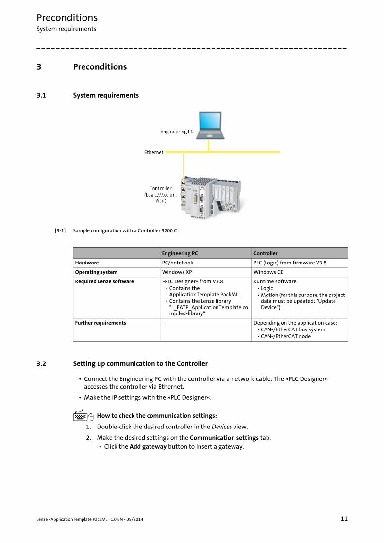
3.1 System requirements
[3-1] Sample configuration with a Controller 3200 C
3.2 Setting up communication to the Controller
• Connect the Engineering PC with the controller via a network cable. The »PLC Designer« accesses the controller via Ethernet.
• Make the IP settings with the »PLC Designer«.
How to check the communication settings:
1. Double-click the desired controller in the Devices view.
2. Make the desired settings on the Communication settings tab.• Click the Add gateway button to insert a gateway.
Engineering PC Controller
Hardware PC/notebook PLC (Logic) from firmware V3.8
Operating system Windows XP Windows CE
Required Lenze software »PLC Designer« from V3.8• Contains the
ApplicationTemplate PackML• Contains the Lenze library
"L_EATP_ApplicationTemplate.compiled-library"
Runtime software• Logic• Motion (for this purpose, the project
data must be updated: "Update Device")
Further requirements - Depending on the application case:• CAN-/EtherCAT bus system• CAN-/EtherCAT node

PreconditionsSetting up communication to the Controller
12 Lenze · ApplicationTemplate PackML · 1.0 EN - 05/2014
_ _ _ _ _ _ _ _ _ _ _ _ _ _ _ _ _ _ _ _ _ _ _ _ _ _ _ _ _ _ _ _ _ _ _ _ _ _ _ _ _ _ _ _ _ _ _ _ _ _ _ _ _ _ _ _ _ _ _ _ _ _ _ _
• Enter the desired IP address of the controller.
[3-2] Example: Enter the IP address of the Controller, standard setting: 192.168.5.99
3. Click OK to add the controller as gateway.
4. By double-clicking the desired channel (or clicking the Set active path button), set the channel selected in the device view below the gateway as active path to the controller.• Thus, all communication actions directly refer to this channel.• The currently active path is represented in bold in the list and "(active)" is attached:
5. A device represented in italics is set as active path but has not been found during the last network scan.
Note!
During initial commissioning, observe the predefined IP address: 192.168.5.99
Further information can be found in the following documentation:
Controller - Parameter setting & configuration

Lenze · ApplicationTemplate PackML · 1.0 EN - 05/2014 13
What is the ApplicationTemplate PackML?Targets of the ApplicationTemplate PackML
_ _ _ _ _ _ _ _ _ _ _ _ _ _ _ _ _ _ _ _ _ _ _ _ _ _ _ _ _ _ _ _ _ _ _ _ _ _ _ _ _ _ _ _ _ _ _ _ _ _ _ _ _ _ _ _ _ _ _ _ _ _ _ _
4 What is the ApplicationTemplate PackML?
The Lenze ApplicationTemplate PackML is an application template for standardised and convenientprogramming in the »PLC Designer« according to PackML standard in compliance with the OMAC("The Organization for Machine Automation and Control").
• From »PLC Designer« version 3.8 onwards, the ApplicationTemplate PackML is included as project template. Create a new project - open the ApplicationTemplate PackML ( 32)
• The L_EATP_ApplicationTemplate.compiled-library library includes the structure and functionality of the standardised Lenze application template and the extension for the ApplicationTemplate PackML. Die Bibliothek L_EATP_ApplicationTemplate ( 89)
4.1 Targets of the ApplicationTemplate PackML
The ApplicationTemplate PackML...
• ...helps to implement the mechatronic structure of an automation system (which has been previously implemented as tree topology) in a modular manner according to the PackML standard.
• ...enables the integration of predefined machine modules with prepared applications/technology modules (for instance the functionality for cross-cutting).
• ...simplifies and speeds up the creation of PLC programs in the long term by re-use of a standardised project structure in the form of a modularised folder structure.
What are the advantages of the ApplicationTemplate PackML?
The ApplicationTemplate PackML facilitates programming with the »PLC Designer« ...
• ...by the defined folder structure which "cleans up" and which can be extended individually.
• ...renders the navigation for extending or creating machine programming easier.
• The ApplicationTemplate PackML contains ready-made, re-usable machine modules and module applications which minimise the risk of compilation errors in order to thus reduce time and costs.

What is the ApplicationTemplate PackML?Features of the Application Sample PackML at a glance
14 Lenze · ApplicationTemplate PackML · 1.0 EN - 05/2014
_ _ _ _ _ _ _ _ _ _ _ _ _ _ _ _ _ _ _ _ _ _ _ _ _ _ _ _ _ _ _ _ _ _ _ _ _ _ _ _ _ _ _ _ _ _ _ _ _ _ _ _ _ _ _ _ _ _ _ _ _ _ _ _
4.2 Features of the Application Sample PackML at a glance
The following predefined functions facilitate implementing a machine application in a PLC:
State machine ( 23)
Alarm handling (error handling) ( 75)
Multitasking ( 82)
Further advantages if the ApplicationTemplate PackML is used:
• Consistent data transfer between the tasks.
• Diagnostic function for every machine module ("generic module diagnosis").
• A defined standard response ("DefaultCoupling") of the state machine. Standard coupling of the machine modules ( 70)
For more information on the respective functions, please see the corresponding subchapter.

Lenze · ApplicationTemplate PackML · 1.0 EN - 05/2014 15
What is the ApplicationTemplate PackML?Elements of the ApplicationTemplate PackML
_ _ _ _ _ _ _ _ _ _ _ _ _ _ _ _ _ _ _ _ _ _ _ _ _ _ _ _ _ _ _ _ _ _ _ _ _ _ _ _ _ _ _ _ _ _ _ _ _ _ _ _ _ _ _ _ _ _ _ _ _ _ _ _
4.3 Elements of the ApplicationTemplate PackML
4.3.1 Machine Module Tree - MMT
In order to map the desired automation system in the »PLC Designer« using theApplicationTemplate PackML, the structure of the whole machine application must be created inthe »PLC Designer«.
• In a first step, the electronic machine structure (total functionality of the machine) has to be divided into machine modules (subfunctions of the machine).
• The A10_MachineModuleTree machine module tree (MMT) shows the machine modules in the form of a tree structure from left to right.
• The top module is the machine control module. The other functions of the machine are subordinated to the machine control module.
[4-1] Illustration example: Machine structure tree (MMT) in the ApplicationTemplate, folder A10_MachineModuleTree
The ApplicationTemplate PackML...
• ...supports two to five hierarchy levels of machine modules.
• ...supports up to 30 machine modules.
[4-2] MMT (Machine Module Tree) with up to five possible hierarchy levels of machine modules
What is the ApplicationTemplate PackML?Elements of the ApplicationTemplate PackML
16 Lenze · ApplicationTemplate PackML · 1.0 EN - 05/2014
_ _ _ _ _ _ _ _ _ _ _ _ _ _ _ _ _ _ _ _ _ _ _ _ _ _ _ _ _ _ _ _ _ _ _ _ _ _ _ _ _ _ _ _ _ _ _ _ _ _ _ _ _ _ _ _ _ _ _ _ _ _ _ _
4.3.2 Machine modules (MM)
The overall functionality of the automation system is structured in a modular manner in theApplicationTemplate PackML. This means that every subfunction of the machine is included in oneof the machine modules. Due to the modular structure, individual (or multiple) subfunctions of amachine can be reused. Advantage: The respective function does not have to be recreated forfurther machine parts.
• A machine module represents the function of a machine part; for instance a conveying belt, or a cross cutter.
• The overall functionality of, for example, a bag form, fill, and seal machine, contains the "Cross cutter" and "Transport unit" subfunctions. The two subfunctions are to be converted to a separate machine module each.
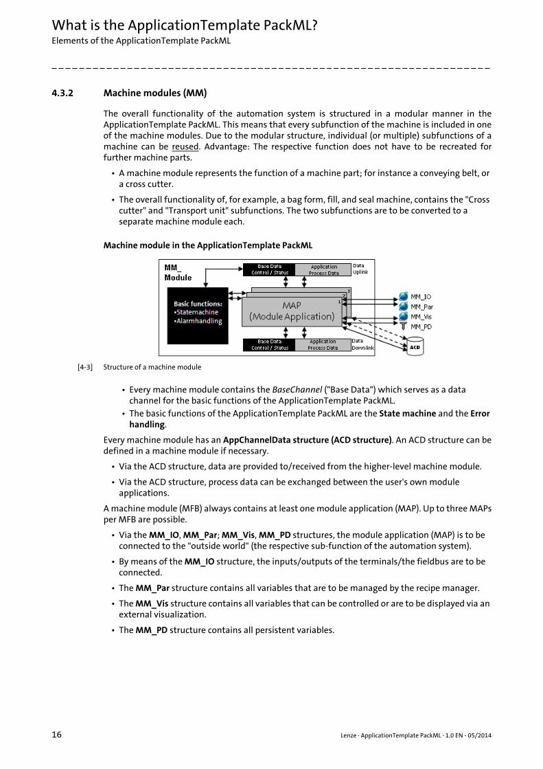
Machine module in the ApplicationTemplate PackML
[4-3] Structure of a machine module
• Every machine module contains the BaseChannel ("Base Data") which serves as a data channel for the basic functions of the ApplicationTemplate PackML.
• The basic functions of the ApplicationTemplate PackML are the State machine and the Error handling.
Every machine module has an AppChannelData structure (ACD structure). An ACD structure can bedefined in a machine module if necessary.
• Via the ACD structure, data are provided to/received from the higher-level machine module.
• Via the ACD structure, process data can be exchanged between the user's own module applications.
A machine module (MFB) always contains at least one module application (MAP). Up to three MAPsper MFB are possible.
• Via the MM_IO, MM_Par; MM_Vis, MM_PD structures, the module application (MAP) is to be connected to the "outside world" (the respective sub-function of the automation system).
• By means of the MM_IO structure, the inputs/outputs of the terminals/the fieldbus are to be connected.
• The MM_Par structure contains all variables that are to be managed by the recipe manager.
• The MM_Vis structure contains all variables that can be controlled or are to be displayed via an external visualization.
• The MM_PD structure contains all persistent variables.

Lenze · ApplicationTemplate PackML · 1.0 EN - 05/2014 17
What is the ApplicationTemplate PackML?Elements of the ApplicationTemplate PackML
_ _ _ _ _ _ _ _ _ _ _ _ _ _ _ _ _ _ _ _ _ _ _ _ _ _ _ _ _ _ _ _ _ _ _ _ _ _ _ _ _ _ _ _ _ _ _ _ _ _ _ _ _ _ _ _ _ _ _ _ _ _ _ _
4.3.3 Addressing the machine modules
[4-4] Illustration example: Sample illustration MMT in the L_ApplicationTemplate sample project
The following must be observed when relative addresses are assigned to the machine modules:
• The relative address is to be assigned to every machine module (value range: 1...29).
• During the initialisation phase, the »PLC Designer« generates an absolute address for every machine module.
• Example of the relative and absolute module addressing:
The diagram shows the absolute module address (black) and the relative module address (white).
• In the event of an error, the absolute address enables an error analysis. This for instance makes it possible to retrace the module which has caused the error in each case. Alarm handling (error handling) ( 75)
4.3.4 Module application (MAP)
The module application (MAP) contains the function of the corresponding machine module.
• The ApplicationTemplate Pack ML supports up to three tasks. Hence, up to three MAPs can be used per machine module.
Every machine module has anMM_Address input whichserves to assign the relativeaddress to the machinemodule.
What is the ApplicationTemplate PackML?Elements of the ApplicationTemplate PackML
18 Lenze · ApplicationTemplate PackML · 1.0 EN - 05/2014
_ _ _ _ _ _ _ _ _ _ _ _ _ _ _ _ _ _ _ _ _ _ _ _ _ _ _ _ _ _ _ _ _ _ _ _ _ _ _ _ _ _ _ _ _ _ _ _ _ _ _ _ _ _ _ _ _ _ _ _ _ _ _ _
• In the A11_ModuleAppCalls folder, the MAPs are to be assigned to the tasks: ModuleAppCalls (MAC).Assigning the module application (ModApp) to the task ( 42)
4.3.5 Modes: Machine operating modes
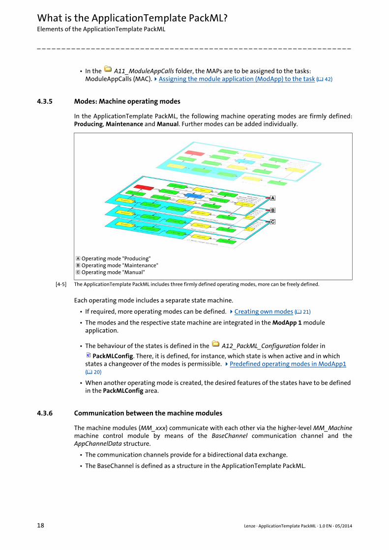
In the ApplicationTemplate PackML, the following machine operating modes are firmly defined:Producing, Maintenance and Manual. Further modes can be added individually.
[4-5] The ApplicationTemplate PackML includes three firmly defined operating modes, more can be freely defined.
Each operating mode includes a separate state machine.
• If required, more operating modes can be defined. Creating own modes ( 21)
• The modes and the respective state machine are integrated in the ModApp 1 module application.
• The behaviour of the states is defined in the A12_PackML_Configuration folder in
PackMLConfig. There, it is defined, for instance, which state is when active and in which states a changeover of the modes is permissible. Predefined operating modes in ModApp1 ( 20)
• When another operating mode is created, the desired features of the states have to be defined in the PackMLConfig area.
4.3.6 Communication between the machine modules
The machine modules (MM_xxx) communicate with each other via the higher-level MM_Machinemachine control module by means of the BaseChannel communication channel and theAppChannelData structure.
• The communication channels provide for a bidirectional data exchange.
• The BaseChannel is defined as a structure in the ApplicationTemplate PackML.
Operating mode "Producing" Operating mode "Maintenance" Operating mode "Manual"
Lenze · ApplicationTemplate PackML · 1.0 EN - 05/2014 19
What is the ApplicationTemplate PackML?Elements of the ApplicationTemplate PackML
_ _ _ _ _ _ _ _ _ _ _ _ _ _ _ _ _ _ _ _ _ _ _ _ _ _ _ _ _ _ _ _ _ _ _ _ _ _ _ _ _ _ _ _ _ _ _ _ _ _ _ _ _ _ _ _ _ _ _ _ _ _ _ _
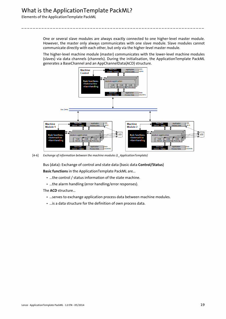
One or several slave modules are always exactly connected to one higher-level master module.However, the master only always communicates with one slave module. Slave modules cannotcommunicate directly with each other, but only via the higher-level master module.
The higher-level machine module (master) communicates with the lower-level machine modules(slaves) via data channels (channels). During the initialisation, the ApplicationTemplate PackMLgenerates a BaseChannel and an AppChannelData(ACD) structure.
[4-6] Exchange of information between the machine modules (L_ApplicationTemplate)
Bus (data): Exchange of control and state data (basic data Control/Status)
Basic functions in the ApplicationTemplate PackML are...
• ...the control / status information of the state machine.
• ...the alarm handling (error handling/error responses).
The ACD structure...
• ...serves to exchange application process data between machine modules.
• ...is a data structure for the definition of own process data.

What is the ApplicationTemplate PackML?Elements of the ApplicationTemplate PackML
20 Lenze · ApplicationTemplate PackML · 1.0 EN - 05/2014
_ _ _ _ _ _ _ _ _ _ _ _ _ _ _ _ _ _ _ _ _ _ _ _ _ _ _ _ _ _ _ _ _ _ _ _ _ _ _ _ _ _ _ _ _ _ _ _ _ _ _ _ _ _ _ _ _ _ _ _ _ _ _ _
4.3.6.1 Predefined operating modes in ModApp1
Each machine module contains the predefined operating modes Producing, Maintenance andManual.
The operating modes are located in the machine module template in the folder
A66_EmptyModule_PackML ModApp1\Modes.
• The module application App1 contains the instances of the mode blocks Producing, Maintenance and Manual.
• The mode block instances are called in the modes method.
Where can the operating modes be defined?
The configuration of the operating modes is defined in the A12_PackMLConfiguration folder.There, it is defined, for instance, which state is active and in which states a changeover of the modeis permissible.
The mode FBs are declared in the MAP-FB in the \ModApp1 folder. Call of the mode FBs in the respective modes method
Lenze · ApplicationTemplate PackML · 1.0 EN - 05/2014 21
What is the ApplicationTemplate PackML?Elements of the ApplicationTemplate PackML
_ _ _ _ _ _ _ _ _ _ _ _ _ _ _ _ _ _ _ _ _ _ _ _ _ _ _ _ _ _ _ _ _ _ _ _ _ _ _ _ _ _ _ _ _ _ _ _ _ _ _ _ _ _ _ _ _ _ _ _ _ _ _ _
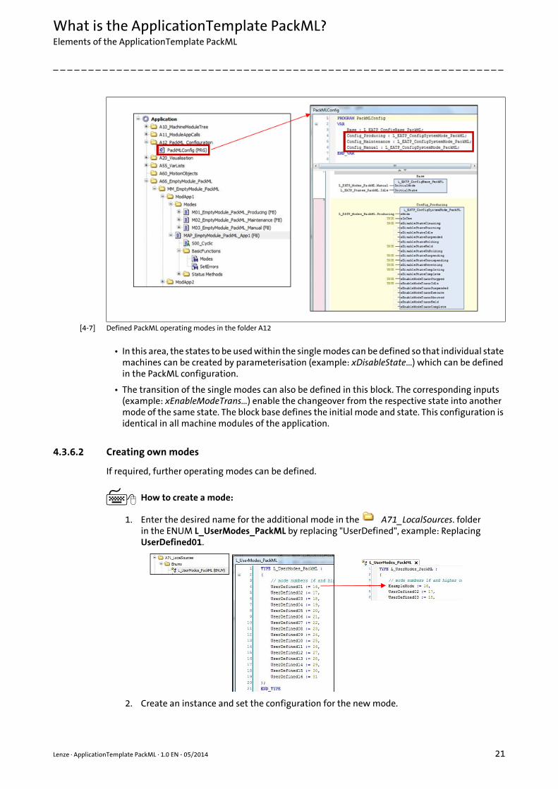
[4-7] Defined PackML operating modes in the folder A12
• In this area, the states to be used within the single modes can be defined so that individual state machines can be created by parameterisation (example: xDisableState…) which can be defined in the PackML configuration.
• The transition of the single modes can also be defined in this block. The corresponding inputs (example: xEnableModeTrans…) enable the changeover from the respective state into another mode of the same state. The block base defines the initial mode and state. This configuration is identical in all machine modules of the application.
4.3.6.2 Creating own modes
If required, further operating modes can be defined.
How to create a mode:
1. Enter the desired name for the additional mode in the A71_LocalSources. folderin the ENUM L_UserModes_PackML by replacing "UserDefined", example: Replacing UserDefined01.
2. Create an instance and set the configuration for the new mode.

What is the ApplicationTemplate PackML?Elements of the ApplicationTemplate PackML
22 Lenze · ApplicationTemplate PackML · 1.0 EN - 05/2014
_ _ _ _ _ _ _ _ _ _ _ _ _ _ _ _ _ _ _ _ _ _ _ _ _ _ _ _ _ _ _ _ _ _ _ _ _ _ _ _ _ _ _ _ _ _ _ _ _ _ _ _ _ _ _ _ _ _ _ _ _ _ _ _
3. Add the ENUM value for this mode to the configuration block.
4. Add the new mode to ModApp1 by copy/paste of an already available mode and rename it, example: ExampleMode.
5. Instance the newly created mode (FB) in the declaration part of the MAP:
6. Add the additional mode to the modes method and assign the ENUM value of the new mode.
Changeover of the operating modes/Modes
After the additional mode has been implemented, the state machine and the changeover of themodes can be operated with the PackML tags.

Lenze · ApplicationTemplate PackML · 1.0 EN - 05/2014 23
What is the ApplicationTemplate PackML?Elements of the ApplicationTemplate PackML
_ _ _ _ _ _ _ _ _ _ _ _ _ _ _ _ _ _ _ _ _ _ _ _ _ _ _ _ _ _ _ _ _ _ _ _ _ _ _ _ _ _ _ _ _ _ _ _ _ _ _ _ _ _ _ _ _ _ _ _ _ _ _ _
An overview of the methods ( 91)
4.3.7 State machine
Each machine module has an own state machine. The state machine of a mode can be createdindividually: By deactivating single states in the entire state machine.
More information: State machine in detail ( 64)
4.3.7.1 State transitions - overview
The following status diagram illustrates the possible state transitions of the state machine:
[4-8] State machine in the ApplicationTemplate PackML
The current state of the state machine is highlighted in red.
• Active state in the illustration: "Idle"
• "Idle" corresponds to the "Waiting" state and is thus highlighted in yellow.
The colouring in the state machine distinguishes the following states:
• Yellow: Waiting state
• Green: Acting state
• Blue: Dual state (can be "waiting" or "acting")
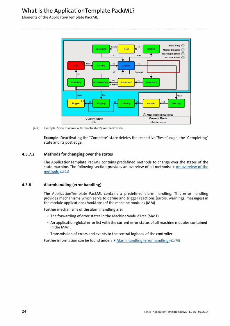
The "waiting" states "Stopped", "Aborted" and "Execute" cannot be deactivated.
Deactivating a state simultaneously switches off the respective (outbound) transitions. If it is the"Wait" state, it also switches off its "Active" state.
Method Description
Command_UnitMode (eUnitMode:= L_UserModes_PackML.ExampleMode, xUnitModeRequest:=TRUE)
Changes over a mode if this is permissible.
Status_ModeChangeAllowed (L_UserModes_PackML.ExampleMode)
Checks if a changeover of the mode is permissible in the current state.
What is the ApplicationTemplate PackML?Elements of the ApplicationTemplate PackML
24 Lenze · ApplicationTemplate PackML · 1.0 EN - 05/2014
_ _ _ _ _ _ _ _ _ _ _ _ _ _ _ _ _ _ _ _ _ _ _ _ _ _ _ _ _ _ _ _ _ _ _ _ _ _ _ _ _ _ _ _ _ _ _ _ _ _ _ _ _ _ _ _ _ _ _ _ _ _ _ _
[4-9] Example: State machine with deactivated "Complete" state.
Example: Deactivating the "Complete" state deletes the respective "Reset" edge, the "Completing"state and its post edge.
4.3.7.2 Methods for changing over the states
The ApplicationTemplate PackML contains predefined methods to change over the states of thestate machine. The following section provides an overview of all methods: An overview of themethods ( 91)
4.3.8 Alarmhandling (error handling)
The ApplicationTemplate PackML contains a predefined alarm handling. This error handlingprovides mechanisms which serve to define and trigger reactions (errors, warnings, messages) inthe module applications (ModApps) of the machine modules (MM).
Further mechanisms of the alarm handling are:
• The forwarding of error states in the MachineModuleTree (MMT).
• An application-global error list with the current error status of all machine modules contained in the MMT.
• Transmission of errors and events to the central logbook of the controller.
Further information can be found under: Alarm handling (error handling) ( 75)

Lenze · ApplicationTemplate PackML · 1.0 EN - 05/2014 25
Structuring the automation system: Standard procedure
_ _ _ _ _ _ _ _ _ _ _ _ _ _ _ _ _ _ _ _ _ _ _ _ _ _ _ _ _ _ _ _ _ _ _ _ _ _ _ _ _ _ _ _ _ _ _ _ _ _ _ _ _ _ _ _ _ _ _ _ _ _ _ _
5 Structuring the automation system: Standard procedure
This section describes the standard procedure to create an application with the »PLC Designer«based on the ApplicationTemplate PackML.
• Use the following recommendations as a guide in order to be able to then create a PLC project in the »PLC Designer« in a structured manner using the ApplicationTemplate PackML and to program it effectively.
• Due to the structured layout of the ApplicationTemplate PackML (the consistency in these structures and the compliance with these structures), applications can be created more quickly and hence integrated in an existing PLC program more quickly.
[5-1] Recommended procedure for creating a project efficiently.
Step Activity What has to be done? Description
Gain an overview of the overall functionality of the machine structure.
• Divide the overall functionality of the machine structure into subfunctions.
• Transfer the identified subfunctions of the machine structure to machine modules.
In this project phase, programming is not yet required! Assign the relative address to the machine modules. ( 27)
Structuring the automation system: Standard procedure
26 Lenze · ApplicationTemplate PackML · 1.0 EN - 05/2014
_ _ _ _ _ _ _ _ _ _ _ _ _ _ _ _ _ _ _ _ _ _ _ _ _ _ _ _ _ _ _ _ _ _ _ _ _ _ _ _ _ _ _ _ _ _ _ _ _ _ _ _ _ _ _ _ _ _ _ _ _ _ _ _
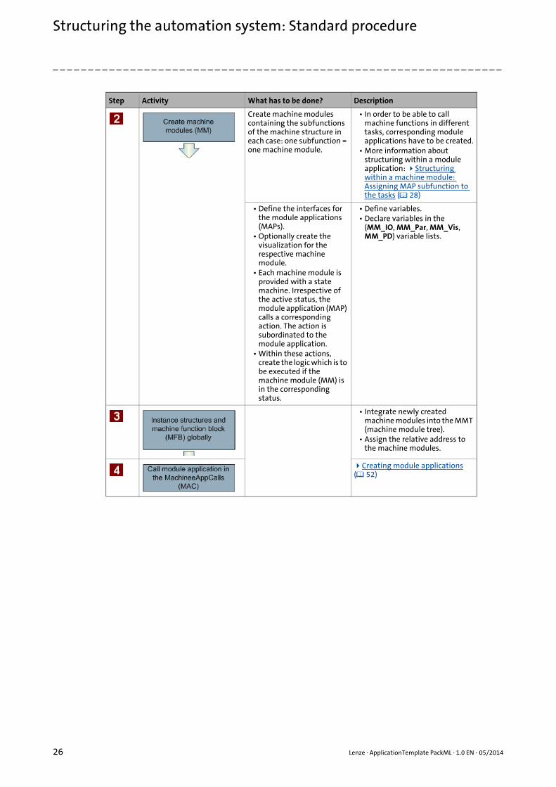
Create machine modules containing the subfunctions of the machine structure in each case: one subfunction = one machine module.
• In order to be able to call machine functions in different tasks, corresponding module applications have to be created.
• More information about structuring within a module application: Structuring within a machine module: Assigning MAP subfunction to the tasks ( 28)
• Define the interfaces for the module applications (MAPs).
• Optionally create the visualization for the respective machine module.
• Each machine module is provided with a state machine. Irrespective of the active status, the module application (MAP) calls a corresponding action. The action is subordinated to the module application.
• Within these actions, create the logic which is to be executed if the machine module (MM) is in the corresponding status.
• Define variables.• Declare variables in the
(MM_IO, MM_Par, MM_Vis, MM_PD) variable lists.
• Integrate newly created machine modules into the MMT (machine module tree).
• Assign the relative address to the machine modules.
Creating module applications ( 52)
Step Activity What has to be done? Description
Lenze · ApplicationTemplate PackML · 1.0 EN - 05/2014 27
Structuring the automation system: Standard procedureAssign the relative address to the machine modules.
_ _ _ _ _ _ _ _ _ _ _ _ _ _ _ _ _ _ _ _ _ _ _ _ _ _ _ _ _ _ _ _ _ _ _ _ _ _ _ _ _ _ _ _ _ _ _ _ _ _ _ _ _ _ _ _ _ _ _ _ _ _ _ _
5.1 Assign the relative address to the machine modules.
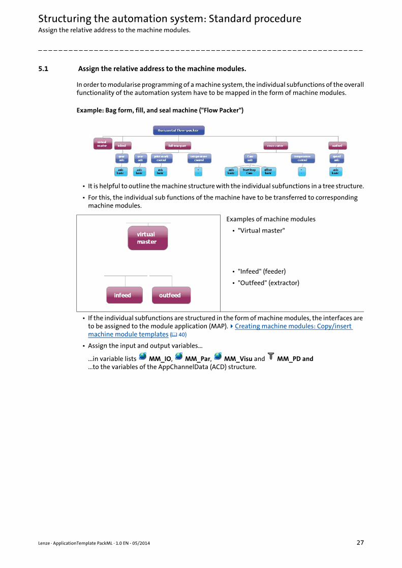
In order to modularise programming of a machine system, the individual subfunctions of the overallfunctionality of the automation system have to be mapped in the form of machine modules.
Example: Bag form, fill, and seal machine ("Flow Packer")
• It is helpful to outline the machine structure with the individual subfunctions in a tree structure.
• For this, the individual sub functions of the machine have to be transferred to corresponding machine modules.
• If the individual subfunctions are structured in the form of machine modules, the interfaces are to be assigned to the module application (MAP).Creating machine modules: Copy/insert machine module templates ( 40)
• Assign the input and output variables...
...in variable lists MM_IO, MM_Par, MM_Visu and MM_PD and
...to the variables of the AppChannelData (ACD) structure.
Examples of machine modules
• "Virtual master"
• "Infeed" (feeder)
• "Outfeed" (extractor)
Structuring the automation system: Standard procedureStructuring within a machine module: Assigning MAP subfunction to the tasks
28 Lenze · ApplicationTemplate PackML · 1.0 EN - 05/2014
_ _ _ _ _ _ _ _ _ _ _ _ _ _ _ _ _ _ _ _ _ _ _ _ _ _ _ _ _ _ _ _ _ _ _ _ _ _ _ _ _ _ _ _ _ _ _ _ _ _ _ _ _ _ _ _ _ _ _ _ _ _ _ _
5.2 Structuring within a machine module: Assigning MAP subfunction to the tasks
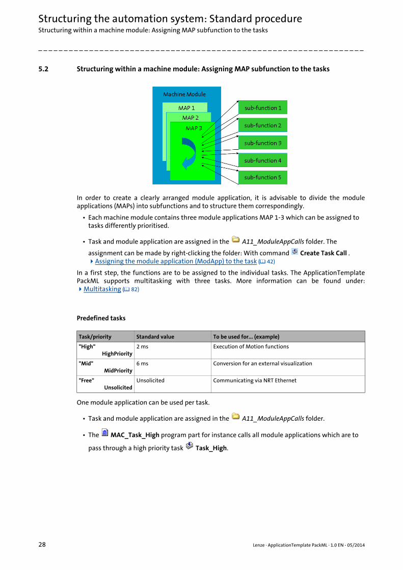
In order to create a clearly arranged module application, it is advisable to divide the moduleapplications (MAPs) into subfunctions and to structure them correspondingly.
• Each machine module contains three module applications MAP 1-3 which can be assigned to tasks differently prioritised.
• Task and module application are assigned in the A11_ModuleAppCalls folder. The
assignment can be made by right-clicking the folder: With command Create Task Call . Assigning the module application (ModApp) to the task ( 42)
In a first step, the functions are to be assigned to the individual tasks. The ApplicationTemplatePackML supports multitasking with three tasks. More information can be found under:Multitasking ( 82)
Predefined tasks
One module application can be used per task.
• Task and module application are assigned in the A11_ModuleAppCalls folder.
• The MAC_Task_High program part for instance calls all module applications which are to
pass through a high priority task Task_High.
Task/priority Standard value To be used for... (example)
"High"HighPriority
2 ms Execution of Motion functions
"Mid"MidPriority
6 ms Conversion for an external visualization
"Free"Unsolicited
Unsolicited Communicating via NRT Ethernet

Lenze · ApplicationTemplate PackML · 1.0 EN - 05/2014 29
Structuring the automation system: Standard procedureStructuring within a machine module: Assigning MAP subfunction to the tasks
_ _ _ _ _ _ _ _ _ _ _ _ _ _ _ _ _ _ _ _ _ _ _ _ _ _ _ _ _ _ _ _ _ _ _ _ _ _ _ _ _ _ _ _ _ _ _ _ _ _ _ _ _ _ _ _ _ _ _ _ _ _ _ _
[5-2] Sample project ApplicationTemplate Counter: MAC_Task_High calls the Module1_App1 module application.
Overview - the folder structure in the ApplicationTemplate PackML
30 Lenze · ApplicationTemplate PackML · 1.0 EN - 05/2014
_ _ _ _ _ _ _ _ _ _ _ _ _ _ _ _ _ _ _ _ _ _ _ _ _ _ _ _ _ _ _ _ _ _ _ _ _ _ _ _ _ _ _ _ _ _ _ _ _ _ _ _ _ _ _ _ _ _ _ _ _ _ _ _
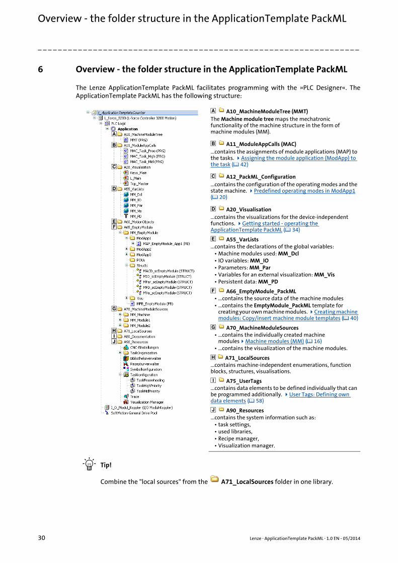
6 Overview - the folder structure in the ApplicationTemplate PackML
The Lenze ApplicationTemplate PackML facilitates programming with the »PLC Designer«. TheApplicationTemplate PackML has the following structure:
Tip!
Combine the "local sources" from the A71_LocalSources folder in one library.
A10_MachineModuleTree (MMT)The Machine module tree maps the mechatronic functionality of the machine structure in the form of machine modules (MM).
A11_ModuleAppCalls (MAC)...contains the assignments of module applications (MAP) to the tasks. Assigning the module application (ModApp) to the task ( 42)
A12_PackML_Configuration...contains the configuration of the operating modes and the state machine. Predefined operating modes in ModApp1 ( 20)
A20_Visualisation...contains the visualizations for the device-independent functions. Getting started - operating the ApplicationTemplate PackML ( 34)
A55_VarLists...contains the declarations of the global variables:
• Machine modules used: MM_Dcl• IO variables: MM_IO• Parameters: MM_Par• Variables for an external visualization: MM_Vis• Persistent data: MM_PD
A66_EmptyModule_PackML• ...contains the source data of the machine modules• ...contains the EmptyModule_PackML template for
creating your own machine modules. Creating machine modules: Copy/insert machine module templates ( 40)
A70_MachineModuleSources• ...contains the individually created machine
modulesMachine modules (MM) ( 16)• ...contains the visualization of the machine modules.
A71_LocalSources...contains machine-independent enumerations, function blocks, structures, visualisations.
A75_UserTags...contains data elements to be defined individually that can be programmed additionally. User Tags: Defining own data elements ( 58)
A90_Resources...contains the system information such as:
• task settings,• used libraries,• Recipe manager,• Visualization manager.
Lenze · ApplicationTemplate PackML · 1.0 EN - 05/2014 31
Opening the ApplicationTemplate PackML
_ _ _ _ _ _ _ _ _ _ _ _ _ _ _ _ _ _ _ _ _ _ _ _ _ _ _ _ _ _ _ _ _ _ _ _ _ _ _ _ _ _ _ _ _ _ _ _ _ _ _ _ _ _ _ _ _ _ _ _ _ _ _ _
7 Opening the ApplicationTemplate PackML
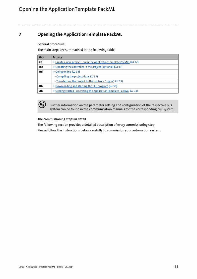
General procedure
The main steps are summarised in the following table:
The commissioning steps in detail
The following section provides a detailed description of every commissioning step.
Please follow the instructions below carefully to commission your automation system.
Step Activity
1st Create a new project - open the ApplicationTemplate PackML ( 32)
2nd Updating the controller in the project (optional) ( 33)
3rd Going online ( 33)
• Compiling the project data ( 33)
• Transferring the project to the control - "Log in" ( 33)
4th Downloading and starting the PLC program ( 33)
5th Getting started - operating the ApplicationTemplate PackML ( 34)
Further information on the parameter setting and configuration of the respective bus system can be found in the communication manuals for the corresponding bus system:

Opening the ApplicationTemplate PackMLCreate a new project - open the ApplicationTemplate PackML
32 Lenze · ApplicationTemplate PackML · 1.0 EN - 05/2014
_ _ _ _ _ _ _ _ _ _ _ _ _ _ _ _ _ _ _ _ _ _ _ _ _ _ _ _ _ _ _ _ _ _ _ _ _ _ _ _ _ _ _ _ _ _ _ _ _ _ _ _ _ _ _ _ _ _ _ _ _ _ _ _
7.1 Create a new project - open the ApplicationTemplate PackML
The ApplicationTemplate PackML is included as a project template (*.project, ) im »PLC Designer«from .3.8 onwards. In order to call the ApplicationTemplate PackML, a new project has to be created,taking the ApplicationTemplate PackML as template.
How to proceed:
1. Creating a new project:
• File New project• Select category Lenze Application Template PackML• Open template L_ApplicationTemplate_PackML
Which template do you want to use? Function
ApplicationTemplate PackML The Lenze application template L_ApplicationTemplatePackML includes a structure predefined by Lenze which serves to...
• ... standardise applications by means of a defined folder structure according to PackML standard.
• ... structure applications by means of machine modules.
Lenze · ApplicationTemplate PackML · 1.0 EN - 05/2014 33
Opening the ApplicationTemplate PackMLUpdating the controller in the project (optional)
_ _ _ _ _ _ _ _ _ _ _ _ _ _ _ _ _ _ _ _ _ _ _ _ _ _ _ _ _ _ _ _ _ _ _ _ _ _ _ _ _ _ _ _ _ _ _ _ _ _ _ _ _ _ _ _ _ _ _ _ _ _ _ _
7.2 Updating the controller in the project (optional)
Cases in which the project must be updated
The controller in the »PLC Designer« must be updated if ...
• ...the project contains firmware information that is older than the hardware to be used or
• ...a controller other than the integrated 3200 C controller is desired (example: p500).
If the controller is marked with the icon after the project is opened, the device information ofthe »PLC Designer« project have to be updated.
Determining the firmware of the controller
How to proceed:
• Use the »WebConfig« to check which firmware is used by the controller to select the appropriate device information in the »PLC Designer«.
7.3 Going online
In order to be able to establish an online connection to the controller, the communication settings(Set active path) must be commissioned before. Setting up communication to the Controller( 11)
7.3.1 Compiling the project data
To compile the project data, select the BuildBuild menu command or press the <F11> functionkey.
• If errors occur during the compilation, they are to be localised on the basis of the »PLC Designer« error messages and corrected correspondingly. Recompile the project data afterwards.
• If no errors occur during the compilation, the »PLC Designer« project must be saved:
File Save project
7.3.2 Transferring the project to the control - "Log in"
The desired project must be transferred to the PLC device by "Logging in" to the controller: Call menu
command Online Log in.
7.4 Downloading and starting the PLC program
• Load the PLC program to the controller: Call OnlineLoad menu command.
Note!
To "log in" the PLC program must be error-free. For this it must be possible to execute the BuildBuild (F11) menu command without an error message.
Opening the ApplicationTemplate PackMLGetting started - operating the ApplicationTemplate PackML
34 Lenze · ApplicationTemplate PackML · 1.0 EN - 05/2014
_ _ _ _ _ _ _ _ _ _ _ _ _ _ _ _ _ _ _ _ _ _ _ _ _ _ _ _ _ _ _ _ _ _ _ _ _ _ _ _ _ _ _ _ _ _ _ _ _ _ _ _ _ _ _ _ _ _ _ _ _ _ _ _
• Start the PLC program: Call OnlineStart menu command.
• As an alternative, you can execute the DebugStart menu command or press <F5>.
Tip!
In order to load a project automatically after a device is restarted, it can be defined as "boot project".
Setting up the project as boot application
How to install the project as boot project:
1. Select the OnlineGenerate boot project for L-force Controller menu command.
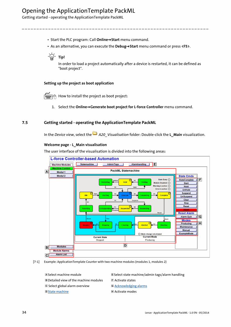
7.5 Getting started - operating the ApplicationTemplate PackML
In the Device view, select the A20_Visualisation folder: Double-click the L_Main visualization.
Welcome page - L_Main visualisation
The user interface of the visualisation is divided into the following areas:
[7-1] Example: ApplicationTemplate Counter with two machine modules (modules 1, modules 2)
Select machine module Select state machine/admin tags/alarm handling
Detailed view of the machine modules Activate states
Select global alarm overview Acknowledging alarms
State machine Activate modes

Lenze · ApplicationTemplate PackML · 1.0 EN - 05/2014 35
Opening the ApplicationTemplate PackMLVisualisation of the machine modules
_ _ _ _ _ _ _ _ _ _ _ _ _ _ _ _ _ _ _ _ _ _ _ _ _ _ _ _ _ _ _ _ _ _ _ _ _ _ _ _ _ _ _ _ _ _ _ _ _ _ _ _ _ _ _ _ _ _ _ _ _ _ _ _
7.6 Visualisation of the machine modules
• If, for instance, Machine Control has been selected, the fields Al[01...04] of L_EATP_Alarm_PackML serve to trigger alarms.
• Possible reactions (Reac.) are: Abort, Stop, Error, SystemFault, Warning, Information.
• The machine module transmits the reaction type to the higher-level machine module. The desired response to the alarm can be programmed individually, except for the commands Abort/Stop.
• If no error response has been programmed, the state machine remains in the current state.
• The Modules button calls the detailed view for the machine modules.
• Click the desired machine module to show the respective status and further details.
• All alarm messages are visible in the global alarm list which can be called via the Alarm List button. The global alarm list provides an overview of all alarms occurred.
• The Alarm Quit button has to be pressed to reset the error. The reason for the tripping has to be removed. Then, the corresponding alarm can be reset.

Working with the ApplicationTemplate PackML
36 Lenze · ApplicationTemplate PackML · 1.0 EN - 05/2014
_ _ _ _ _ _ _ _ _ _ _ _ _ _ _ _ _ _ _ _ _ _ _ _ _ _ _ _ _ _ _ _ _ _ _ _ _ _ _ _ _ _ _ _ _ _ _ _ _ _ _ _ _ _ _ _ _ _ _ _ _ _ _ _
8 Working with the ApplicationTemplate PackML
This chapter provides information on how to create machine modules in the ApplicationTemplatePackML using the machine module template EmptyModule_PackML. EmptyModule_PackML is atemplate for making the creation of your own machine modules easier.
Programming with the ApplicationTemplate PackML: What has to be done?
Step Activity Detailed information
1. Structuring the automation system• The overall functionality (machine
application) of the automation system is to be mapped modularly:One subfunction = one machine module
• In this project phase, programming is not yet required!
Assign the relative address to the machine modules. ( 27)
2. Starting the ApplicationTemplate PackML Opening the ApplicationTemplate PackML ( 31)
3. Updating the project (optional)• Adjust the device information version in the
»PLC Designer« project to the firmware version of the controller.
• Integrate another controller in the project if required. The controller included is the 3200 C.
Updating the controller in the project (optional) ( 33)
4. Mapping the actual machine structure in the »PLC Designer«
Mapping the actual machine structure: Add devices ( 37)
6. Creating/integrating individual machine modules
Creating machine modules: Copy/insert machine module templates ( 40)
7. Integrating devices Inserting an axis ( 48)
Integrating I/O modules of the I/O system 1000 with a machine module ( 50)
Integrating a module application ( 54)
8. Going online Going online ( 33)
9. Starting the PLC program Downloading and starting the PLC program ( 33)
Lenze · ApplicationTemplate PackML · 1.0 EN - 05/2014 37
Working with the ApplicationTemplate PackMLMapping the actual machine structure: Add devices
_ _ _ _ _ _ _ _ _ _ _ _ _ _ _ _ _ _ _ _ _ _ _ _ _ _ _ _ _ _ _ _ _ _ _ _ _ _ _ _ _ _ _ _ _ _ _ _ _ _ _ _ _ _ _ _ _ _ _ _ _ _ _ _
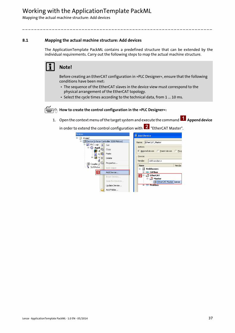
8.1 Mapping the actual machine structure: Add devices
The ApplicationTemplate PackML contains a predefined structure that can be extended by theindividual requirements. Carry out the following steps to map the actual machine structure.
How to create the control configuration in the »PLC Designer«:
1. Open the context menu of the target system and execute the command Append device
in order to extend the control configuration with "EtherCAT Master".
Note!
Before creating an EtherCAT configuration in »PLC Designer«, ensure that the following conditions have been met:• The sequence of the EtherCAT slaves in the device view must correspond to the
physical arrangement of the EtherCAT topology.• Select the cycle times according to the technical data, from 1 ... 10 ms.

Working with the ApplicationTemplate PackMLMapping the actual machine structure: Add devices
38 Lenze · ApplicationTemplate PackML · 1.0 EN - 05/2014
_ _ _ _ _ _ _ _ _ _ _ _ _ _ _ _ _ _ _ _ _ _ _ _ _ _ _ _ _ _ _ _ _ _ _ _ _ _ _ _ _ _ _ _ _ _ _ _ _ _ _ _ _ _ _ _ _ _ _ _ _ _ _ _
2. Add an EtherCAT slave below the EtherCAT Master: Right-click the EtherCAT Master
Add device:
Select the desired device from the selection list .
The »PLC Designer« provides a "fieldbus scan" during which the devices connected to the fieldbus are automatically detected.
Further information is provided in the "Controller-based Automation EtherCAT" section of the online help for the »PLC Designer« and in the Controller-based Automation EtherCAT communication manual (KHB).
Repeat the Add device until all slaves connected to the fieldbus are implemented in the device view.
Allocate unique designations to the slaves inserted(example: "L_94_HL_ActuatorSpeed").
The names can be selected freely and must …• only contain the characters "A ... Z", "a ... z", "0 ... 9", or "_";• not start with a digit.
You can enter a name by clicking the element.
Example:
Lenze · ApplicationTemplate PackML · 1.0 EN - 05/2014 39
Working with the ApplicationTemplate PackMLMapping the actual machine structure: Add devices
_ _ _ _ _ _ _ _ _ _ _ _ _ _ _ _ _ _ _ _ _ _ _ _ _ _ _ _ _ _ _ _ _ _ _ _ _ _ _ _ _ _ _ _ _ _ _ _ _ _ _ _ _ _ _ _ _ _ _ _ _ _ _ _
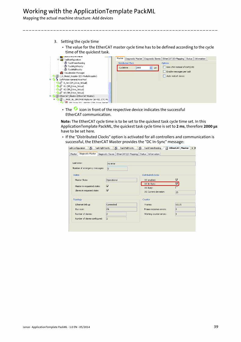
3. Setting the cycle time• The value for the EtherCAT master cycle time has to be defined according to the cycle
time of the quickest task.
• The icon in front of the respective device indicates the successfulEtherCAT communication.
Note: The EtherCAT cycle time is to be set to the quickest task cycle time set. In this ApplicationTemplate PackML, the quickest task cycle time is set to 2 ms, therefore 2000 μs have to be set here.• If the "Distributed Clocks" option is activated for all controllers and communication is
successful, the EtherCAT Master provides the "DC In-Sync" message:

Working with the ApplicationTemplate PackMLCreating machine modules: Copy/insert machine module templates
40 Lenze · ApplicationTemplate PackML · 1.0 EN - 05/2014
_ _ _ _ _ _ _ _ _ _ _ _ _ _ _ _ _ _ _ _ _ _ _ _ _ _ _ _ _ _ _ _ _ _ _ _ _ _ _ _ _ _ _ _ _ _ _ _ _ _ _ _ _ _ _ _ _ _ _ _ _ _ _ _
8.2 Creating machine modules: Copy/insert machine module templates
Tip!
If individual machine modules are created, the ApplicationTemplate PackML automaticallyassigns the corresponding machine module-internal names.
Creating machine modules: What has to be done?
How to proceed:
1. Copy the EmptyModule_PackML machine module template:
• Right-click the A66 EmptyModule_PackML\MM_EmptyModule_PackML folderCopy Empty Module.
2. Insert the previously copied machine module (MM_Empty Module_PackML) below the
A70_MachineModuleSources folder:
• Right-click the A70_MachineModuleSources Insert Empty Module
3. Enter the desired module name.
The module name can be selected freely and …• must not contain "MM_"• may only contain the characters "A ... Z", "a ... z", "0 ... 9"• must not contain any special characters.
4. Click Insert to insert the machine module.• The machine module has been inserted with the applicable names of the MAPs/MFB,
structures, and visualization.• The machine module is instanced with the previously assigned name.
5. The machine module inserted (MFB_*) is to be inserted in the MMT in the
A10_MachineModuleTree folder. Integrating machine modules in the MMT
6. The module application (MAP_*) in the A11_ModuleAppCalls folder is to be inserted in the desired module application call (MAC_Task_*). Assigning the module application (ModApp) to the task
The machine module template EmptyModule_PackML...
• ...has to be copied in the A66 EmptyModule_PackML
folder using the Copy Empty Module command and
• ...then using the Insert Empty Module command to
insert it into the A70_MachineModuleSources folder.

Lenze · ApplicationTemplate PackML · 1.0 EN - 05/2014 41
Working with the ApplicationTemplate PackMLIntegrating machine modules in the MMT
_ _ _ _ _ _ _ _ _ _ _ _ _ _ _ _ _ _ _ _ _ _ _ _ _ _ _ _ _ _ _ _ _ _ _ _ _ _ _ _ _ _ _ _ _ _ _ _ _ _ _ _ _ _ _ _ _ _ _ _ _ _ _ _
8.3 Integrating machine modules in the MMT
A machine module (created on the basis of the EmptyModule_PackML machine module template)has to be integrated into the MachineModuleTree (MMT) in order to integrate it functionally intothe ApplicationTemplate PackML.
[8-1] Example: MachineModuleTree in the ApplicationTemplate PackML
How to proceed:
1. Double-click the A10_MachineModuleTree folder in the device view.
• Double-click MMT (PRG).Note: The programming language of MMT (PRG) is CFC (Continuous Function Chart).
• In the Tools dialog window, click the Block button.• Create the new FB via drag-and-drop.
• Double-click the area of the FB, click the button.
Use the Input assistance from the Application element...• ...to assign the MFB_CrossCutter FB.• ...to assign the CrossCutter instance.
Note: Go to the Input assistant and select the Insert with namespace prefix when assigning the instance name.
2. Specify the relative address for the machine module.
• In the Tools dialog window, click the Input button.• Add the new input at MM_Address• Assign the relative address (example: "3").
Working with the ApplicationTemplate PackMLAssigning the module application (ModApp) to the task
42 Lenze · ApplicationTemplate PackML · 1.0 EN - 05/2014
_ _ _ _ _ _ _ _ _ _ _ _ _ _ _ _ _ _ _ _ _ _ _ _ _ _ _ _ _ _ _ _ _ _ _ _ _ _ _ _ _ _ _ _ _ _ _ _ _ _ _ _ _ _ _ _ _ _ _ _ _ _ _ _
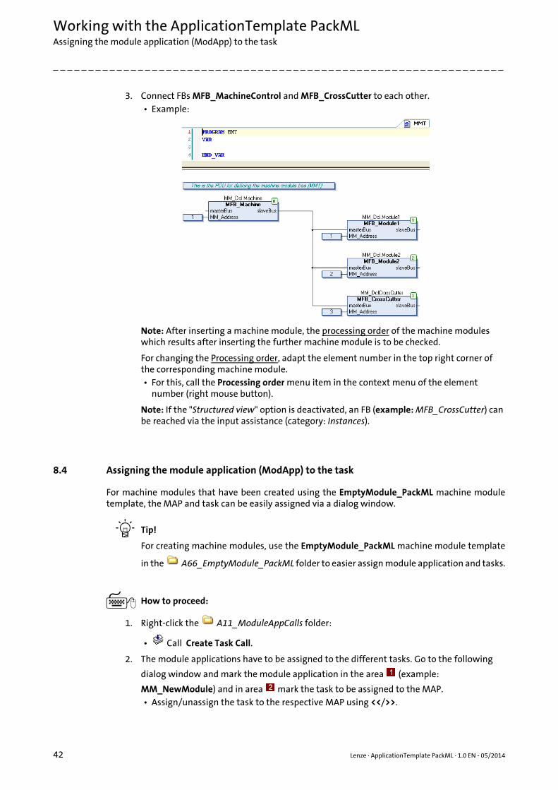
3. Connect FBs MFB_MachineControl and MFB_CrossCutter to each other.• Example:
Note: After inserting a machine module, the processing order of the machine modules which results after inserting the further machine module is to be checked.
For changing the Processing order, adapt the element number in the top right corner of the corresponding machine module.• For this, call the Processing order menu item in the context menu of the element
number (right mouse button).
Note: If the "Structured view" option is deactivated, an FB (example: MFB_CrossCutter) can be reached via the input assistance (category: Instances).
8.4 Assigning the module application (ModApp) to the task
For machine modules that have been created using the EmptyModule_PackML machine moduletemplate, the MAP and task can be easily assigned via a dialog window.
Tip!
For creating machine modules, use the EmptyModule_PackML machine module template
in the A66_EmptyModule_PackML folder to easier assign module application and tasks.
How to proceed:
1. Right-click the A11_ModuleAppCalls folder:
• Call Create Task Call.
2. The module applications have to be assigned to the different tasks. Go to the following
dialog window and mark the module application in the area (example:
MM_NewModule) and in area mark the task to be assigned to the MAP.• Assign/unassign the task to the respective MAP using <</>>.

Lenze · ApplicationTemplate PackML · 1.0 EN - 05/2014 43
Working with the ApplicationTemplate PackMLAssigning the module application (ModApp) to the task
_ _ _ _ _ _ _ _ _ _ _ _ _ _ _ _ _ _ _ _ _ _ _ _ _ _ _ _ _ _ _ _ _ _ _ _ _ _ _ _ _ _ _ _ _ _ _ _ _ _ _ _ _ _ _ _ _ _ _ _ _ _ _ _
[8-2] Example: ModuleApp1 is assigned to the task with the highest priority Task_High.
• Confirm assignment by clicking OK.
The functions of the machine module can be programmed in the "State" methods of the singleoperating modes.
States: States with predefined functions
[8-3] The states of the state machine contain a predefined programming
Each state of the state machine already contains a predefined programming.
• By double-clicking the prevailing state, the program code that contains the commented user functions becomes visible.
• The comments point out where further functions can be added.
Working with the ApplicationTemplate PackMLCreate MM Instance: Creating instances of a machine module
44 Lenze · ApplicationTemplate PackML · 1.0 EN - 05/2014
_ _ _ _ _ _ _ _ _ _ _ _ _ _ _ _ _ _ _ _ _ _ _ _ _ _ _ _ _ _ _ _ _ _ _ _ _ _ _ _ _ _ _ _ _ _ _ _ _ _ _ _ _ _ _ _ _ _ _ _ _ _ _ _
• The MAP block contains the S00_Cyclic action which is processed cyclically.
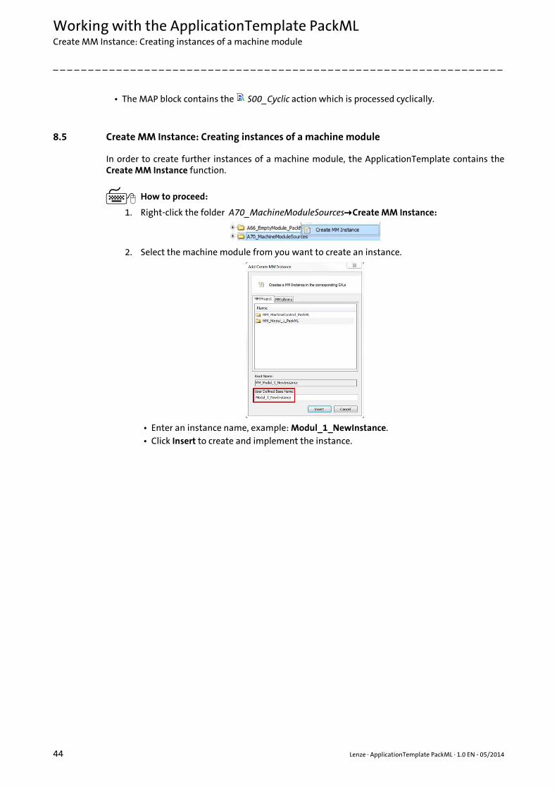
8.5 Create MM Instance: Creating instances of a machine module
In order to create further instances of a machine module, the ApplicationTemplate contains theCreate MM Instance function.
How to proceed:
1. Right-click the folder A70_MachineModuleSourcesCreate MM Instance:
2. Select the machine module from you want to create an instance.
• Enter an instance name, example: Modul_1_NewInstance.• Click Insert to create and implement the instance.

Lenze · ApplicationTemplate PackML · 1.0 EN - 05/2014 45
Working with the ApplicationTemplate PackMLDelete Machine Module: Remove instances of a machine module
_ _ _ _ _ _ _ _ _ _ _ _ _ _ _ _ _ _ _ _ _ _ _ _ _ _ _ _ _ _ _ _ _ _ _ _ _ _ _ _ _ _ _ _ _ _ _ _ _ _ _ _ _ _ _ _ _ _ _ _ _ _ _ _
8.6 Delete Machine Module: Remove instances of a machine module
In order to delete the instance of a machine module, the ApplicationTemplate contains the DeleteMachine Module References function.
• Executing the command causes all entries in the data containers and calls to be deleted.
Manual removal of the instances
The instances of a machine module have to be removed from the global variable lists in the
A55_VarLists folder.
How to proceed:
1. Double-click the A55_VarLists folder.
2. Double-click the global MM_Dcl variable list.
3. Right-click the instance to be deleted (example: NewModule):
Working with the ApplicationTemplate PackMLRemoving machine modules
46 Lenze · ApplicationTemplate PackML · 1.0 EN - 05/2014
_ _ _ _ _ _ _ _ _ _ _ _ _ _ _ _ _ _ _ _ _ _ _ _ _ _ _ _ _ _ _ _ _ _ _ _ _ _ _ _ _ _ _ _ _ _ _ _ _ _ _ _ _ _ _ _ _ _ _ _ _ _ _ _
8.7 Removing machine modules
In order to remove a machine module including all instances from the »PLC Designer« project,
execute the Delete command.
How to proceed:
Right-click the module name in the A70_MachineModuleSources folder and execute
the Delete command.
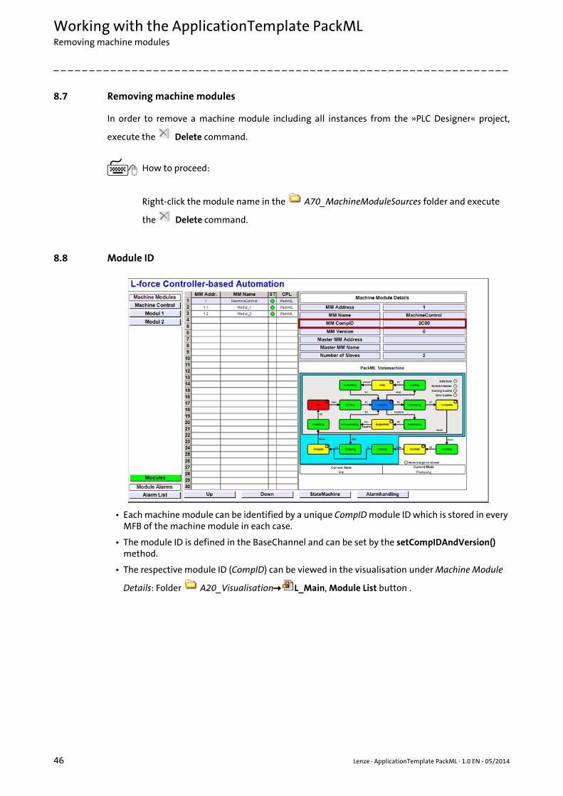
8.8 Module ID
• Each machine module can be identified by a unique CompID module ID which is stored in every MFB of the machine module in each case.
• The module ID is defined in the BaseChannel and can be set by the setCompIDAndVersion() method.
• The respective module ID (CompID) can be viewed in the visualisation under Machine Module
Details: Folder A20_Visualisation L_Main, Module List button .
Lenze · ApplicationTemplate PackML · 1.0 EN - 05/2014 47
Working with the ApplicationTemplate PackMLModule ID
_ _ _ _ _ _ _ _ _ _ _ _ _ _ _ _ _ _ _ _ _ _ _ _ _ _ _ _ _ _ _ _ _ _ _ _ _ _ _ _ _ _ _ _ _ _ _ _ _ _ _ _ _ _ _ _ _ _ _ _ _ _ _ _
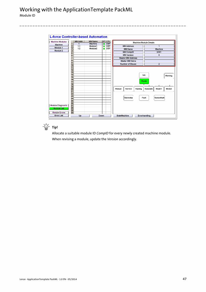
Tip!
Allocate a suitable module ID CompID for every newly created machine module.
When revising a module, update the Version accordingly.

Working with the ApplicationTemplate PackMLInserting an axis
48 Lenze · ApplicationTemplate PackML · 1.0 EN - 05/2014
_ _ _ _ _ _ _ _ _ _ _ _ _ _ _ _ _ _ _ _ _ _ _ _ _ _ _ _ _ _ _ _ _ _ _ _ _ _ _ _ _ _ _ _ _ _ _ _ _ _ _ _ _ _ _ _ _ _ _ _ _ _ _ _
8.9 Inserting an axis
In order to connect an axis to a machine module, the following has to be observed when creating amachine module.
• The following example shows how an axis is to be connected to the MM_Module2 machine module.
• The axis is to be connected to the task with the highest priority MAC_Task_High.
How to proceed:
1. Call the module application within which an axis is to be connected:
• Extend the module application by the declaration: AXIS: AXIS_REF_SM3
2. In the A11_ModuleAppCalls folder, update the task into which the module application
is integrated: MAC_Task_High• Delete the present module name (here: MAP2_Modul2_App1) in the FB of the module
application:
3. Assign the name of the module application (example: MAP_Module2_App1) to the FB:

Lenze · ApplicationTemplate PackML · 1.0 EN - 05/2014 49
Working with the ApplicationTemplate PackMLInserting an axis
_ _ _ _ _ _ _ _ _ _ _ _ _ _ _ _ _ _ _ _ _ _ _ _ _ _ _ _ _ _ _ _ _ _ _ _ _ _ _ _ _ _ _ _ _ _ _ _ _ _ _ _ _ _ _ _ _ _ _ _ _ _ _ _
4. Assign the name of the instance (example: MM_Dcl.Module2.App1) to the module application:
5. Assign the axis to the module application. The precondition for this is that the actual machine structure is mapped in the »PLC Designer« project. Mapping the actual machine structure: Add devices ( 37)(The dwTestCounter input does not receive a transfer variable.)
• Select the desired axis (example: SM_Drive_ETC_9400HL)• Click OK to insert the axis.• The axis is connected to the machine module:
Working with the ApplicationTemplate PackMLIntegrating I/O modules of the I/O system 1000 with a machine module
50 Lenze · ApplicationTemplate PackML · 1.0 EN - 05/2014
_ _ _ _ _ _ _ _ _ _ _ _ _ _ _ _ _ _ _ _ _ _ _ _ _ _ _ _ _ _ _ _ _ _ _ _ _ _ _ _ _ _ _ _ _ _ _ _ _ _ _ _ _ _ _ _ _ _ _ _ _ _ _ _
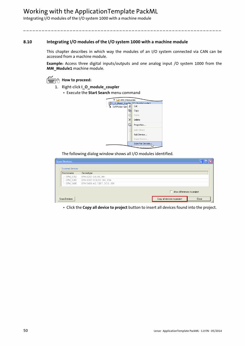
8.10 Integrating I/O modules of the I/O system 1000 with a machine module
This chapter describes in which way the modules of an I/O system connected via CAN can beaccessed from a machine module.
Example: Access three digital inputs/outputs and one analog input /O system 1000 from theMM_Module1 machine module.
How to proceed:
1. Right-click I_O_module_coupler• Execute the Start Search menu command
The following dialog window shows all I/O modules identified.
• Click the Copy all device to project button to insert all devices found into the project.

Lenze · ApplicationTemplate PackML · 1.0 EN - 05/2014 51
Working with the ApplicationTemplate PackMLIntegrating I/O modules of the I/O system 1000 with a machine module
_ _ _ _ _ _ _ _ _ _ _ _ _ _ _ _ _ _ _ _ _ _ _ _ _ _ _ _ _ _ _ _ _ _ _ _ _ _ _ _ _ _ _ _ _ _ _ _ _ _ _ _ _ _ _ _ _ _ _ _ _ _ _ _
2. The variable names that are used in the machine module and that are connected to the I/O system are summarised in the MM_IO structure.
3. Assign the variables to the physical I/O modules.
4. Activate the Always update variables option by ticking the checkbox ():

Working with the ApplicationTemplate PackMLCreating module applications
52 Lenze · ApplicationTemplate PackML · 1.0 EN - 05/2014
_ _ _ _ _ _ _ _ _ _ _ _ _ _ _ _ _ _ _ _ _ _ _ _ _ _ _ _ _ _ _ _ _ _ _ _ _ _ _ _ _ _ _ _ _ _ _ _ _ _ _ _ _ _ _ _ _ _ _ _ _ _ _ _
8.11 Creating module applications
This chapter describes how to create a module application.
Tip!
In the ApplicationTemplate PackML, all positions that are to be edited if a new moduleapplication is to be created are marked with theAT_ACTION_CREATE_NEW_MODULEAPPLICATION keyword.
The search function in the »PLC Designer« makes it easier to find the positions to be edited:• Execute the menu command EditFind&replaceFind• Enter the required keyword and search/continue to search in order to navigate to the
corresponding positions in the ApplicationTemplate PackML.
Example: Extend the MM_Module1 machine module by a module application.
How to create a module application:
1. Copy the MM_Module1\ModApp1 folder (right click: Copy) and insert it in the
MM_Module1 folder (right click: Paste).
Rename the following elements (by right click Properties):
• The folder name (previously: ModApp1): ModApp2
• Initial situation:• A machine module (example:
MM_Module1) is to be extended by a module application.
• Create the module application in the following folder of the machine module:
MM_Module1\ModApp1
Lenze · ApplicationTemplate PackML · 1.0 EN - 05/2014 53
Working with the ApplicationTemplate PackMLCreating module applications
_ _ _ _ _ _ _ _ _ _ _ _ _ _ _ _ _ _ _ _ _ _ _ _ _ _ _ _ _ _ _ _ _ _ _ _ _ _ _ _ _ _ _ _ _ _ _ _ _ _ _ _ _ _ _ _ _ _ _ _ _ _ _ _
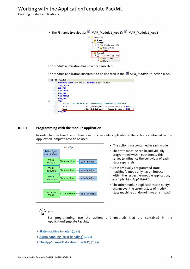
• The FB name (previously: MAP_Module1_App1): MAP_Module1_App2
The module application has now been inserted.
The module application inserted is to be declared in the MFB_Module1 function block:
8.11.1 Programming with the module application
In order to structure the subfunctions of a module applications, the actions contained in theApplicationTemplate have to be used.
Tip!
For programming, use the actions and methods that are contained in theApplicationTemplate PackML.
State machine in detail ( 64)
Alarm handling (error handling) ( 75)
The AppChannelData structure(ACD) ( 59)
• The actions are contained in each mode.
• The state machine can be individually programmed within each mode. This serves to influence the behaviour of each state separately.
• An individually programmed state machine/a mode only has an impact within the respective module application, example: ModApp1/MAP 1.
• The other module applications can query/changeover the current state of mode/state machine but do not have any impact.

Working with the ApplicationTemplate PackMLCreating module applications
54 Lenze · ApplicationTemplate PackML · 1.0 EN - 05/2014
_ _ _ _ _ _ _ _ _ _ _ _ _ _ _ _ _ _ _ _ _ _ _ _ _ _ _ _ _ _ _ _ _ _ _ _ _ _ _ _ _ _ _ _ _ _ _ _ _ _ _ _ _ _ _ _ _ _ _ _ _ _ _ _
8.11.2 Integrating a module application
This section describes the procedure for integrating a newly created module application into amachine module.
Tip!
In the ApplicationTemplate, all positions that are to be edited if a new module applicationis to be integrated are marked with the AT_ACTION_ADD_MODULEAPPLICATION keyword.
The search function in the »PLC Designer« makes it easier to find the positions to be edited:• Execute the menu command EditFind&replaceFind.• Enter the required keyword and search/continue to search in order to navigate to the
corresponding positions in the ApplicationTemplate PackML.
Example: Integration of the module application into the Task_Mid task.
How to integrate a module application:
Taking the MM_Module1 machine module as a basis, the example shows how the newly createdApp2 module application is to be integrated into the ApplicationTemplate PackML.
1. Call of the newly created module application in the corresponding task
( A11_ModuleAppCalls folder, MAC_Task_Mid block).• Highlight the MAP_Module block.
• Copy and Paste the block (right click: Copy/ Paste)
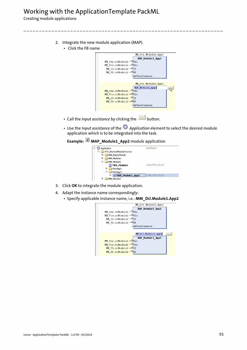
Lenze · ApplicationTemplate PackML · 1.0 EN - 05/2014 55
Working with the ApplicationTemplate PackMLCreating module applications
_ _ _ _ _ _ _ _ _ _ _ _ _ _ _ _ _ _ _ _ _ _ _ _ _ _ _ _ _ _ _ _ _ _ _ _ _ _ _ _ _ _ _ _ _ _ _ _ _ _ _ _ _ _ _ _ _ _ _ _ _ _ _ _
2. Integrate the new module application (MAP).• Click the FB name
• Call the Input assistance by clicking the button.
• Use the Input assistance of the Application element to select the desired module application which is to be integrated into the task.
Example: MAP_Module1_App2 module application
3. Click OK to integrate the module application.
4. Adapt the instance name correspondingly:• Specify applicable instance name, i.e.: MM_Dcl.Module1.App2
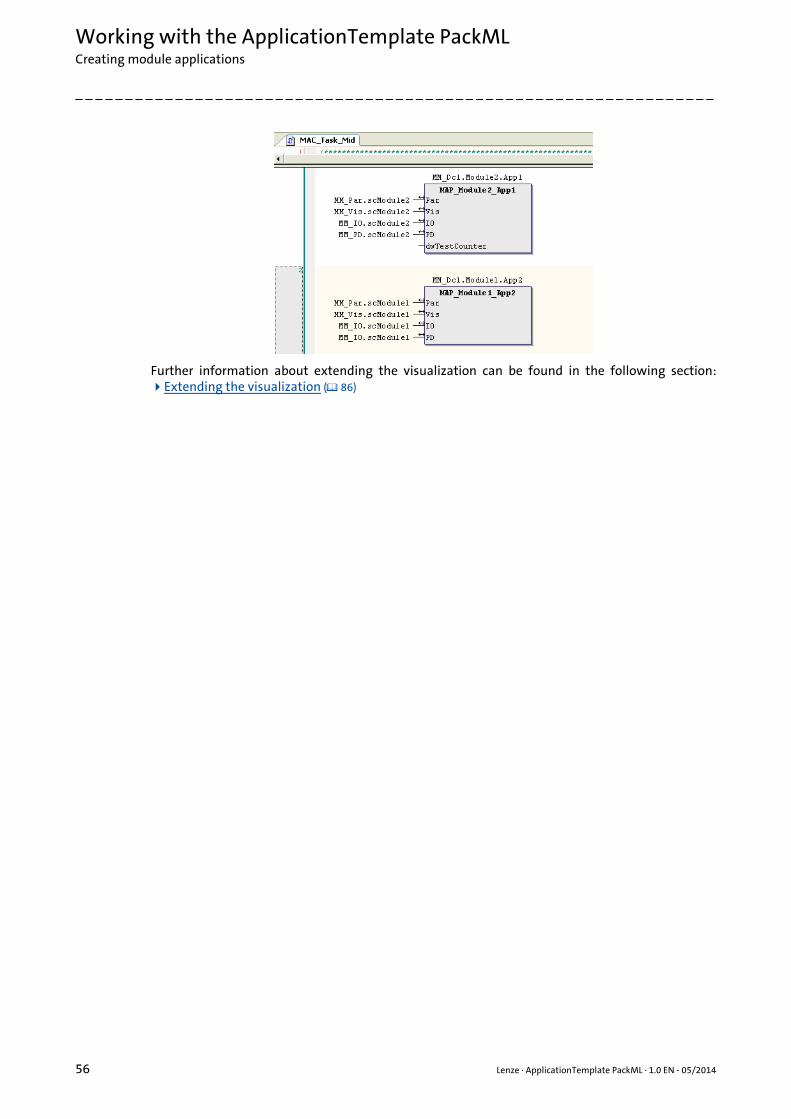
Working with the ApplicationTemplate PackMLCreating module applications
56 Lenze · ApplicationTemplate PackML · 1.0 EN - 05/2014
_ _ _ _ _ _ _ _ _ _ _ _ _ _ _ _ _ _ _ _ _ _ _ _ _ _ _ _ _ _ _ _ _ _ _ _ _ _ _ _ _ _ _ _ _ _ _ _ _ _ _ _ _ _ _ _ _ _ _ _ _ _ _ _
Further information about extending the visualization can be found in the following section:Extending the visualization ( 86)
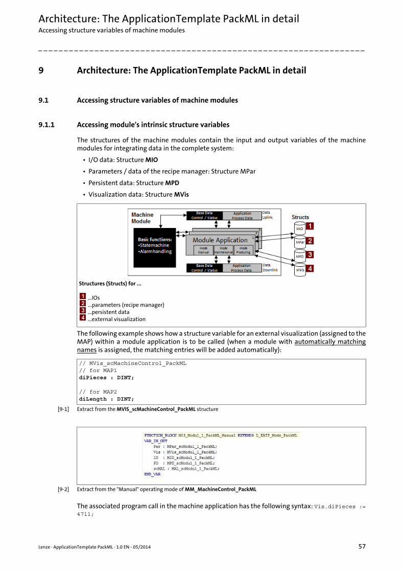
Lenze · ApplicationTemplate PackML · 1.0 EN - 05/2014 57
Architecture: The ApplicationTemplate PackML in detailAccessing structure variables of machine modules
_ _ _ _ _ _ _ _ _ _ _ _ _ _ _ _ _ _ _ _ _ _ _ _ _ _ _ _ _ _ _ _ _ _ _ _ _ _ _ _ _ _ _ _ _ _ _ _ _ _ _ _ _ _ _ _ _ _ _ _ _ _ _ _
9 Architecture: The ApplicationTemplate PackML in detail
9.1 Accessing structure variables of machine modules
9.1.1 Accessing module's intrinsic structure variables
The structures of the machine modules contain the input and output variables of the machinemodules for integrating data in the complete system:
• I/O data: Structure MIO
• Parameters / data of the recipe manager: Structure MPar
• Persistent data: Structure MPD
• Visualization data: Structure MVis
The following example shows how a structure variable for an external visualization (assigned to theMAP) within a module application is to be called (when a module with automatically matchingnames is assigned, the matching entries will be added automatically):
[9-1] Extract from the MVIS_scMachineControl_PackML structure
[9-2] Extract from the "Manual" operating mode of MM_MachineControl_PackML
The associated program call in the machine application has the following syntax: Vis.diPieces :=4711;
Structures (Structs) for ...
...IOs
...parameters (recipe manager)
...persistent data
...external visualization
// MVis_scMachineControl_PackML// for MAP1diPieces : DINT;
// for MAP2diLength : DINT;
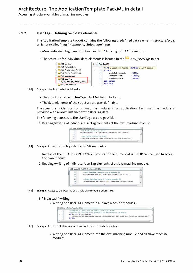
Architecture: The ApplicationTemplate PackML in detailAccessing structure variables of machine modules
58 Lenze · ApplicationTemplate PackML · 1.0 EN - 05/2014
_ _ _ _ _ _ _ _ _ _ _ _ _ _ _ _ _ _ _ _ _ _ _ _ _ _ _ _ _ _ _ _ _ _ _ _ _ _ _ _ _ _ _ _ _ _ _ _ _ _ _ _ _ _ _ _ _ _ _ _ _ _ _ _
9.1.2 User Tags: Defining own data elements
The ApplicationTemplate PackML contains the following predefined data elements structure/type,which are called "tags": command, status, admin tag.
• More individual tags can be defined in the UserTags_PackML structure.
• The structure for individual data elements is located in the A75_UserTags folder.
[9-3] Example: UserTag created individually
• The structure name L_UserTags_PackML has to be kept.
• The data elements of the structure are user-definable.
The structure is identical for all machine modules in an application. Each machine module isprovided with an own instance of the UserTag data.
The following accesses to the UserTag data are possible:
1. Reading/writing of individual UserTag elements of the own machine module.
[9-4] Example: Access to a UserTag in state action S04, own module.
Instead of the L_EATP_CONST.OWNID constant, the numerical value "0" can be used to access the own module.
2. Reading/writing of individual UserTag elements of a slave machine module.
[9-5] Example: Access to the UserTag of a single slave module, address 96.
3. "Broadcast" writing:• Writing of a UserTag element in all slave machine modules.
[9-6] Example: Access to all slave modules, without the own machine module.
• Writing of a UserTag element into the own machine module and all slave machine modules.
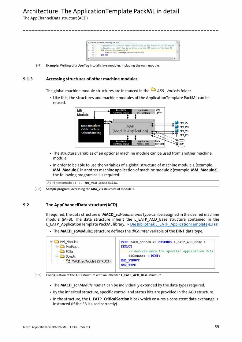
Lenze · ApplicationTemplate PackML · 1.0 EN - 05/2014 59
Architecture: The ApplicationTemplate PackML in detailThe AppChannelData structure(ACD)
_ _ _ _ _ _ _ _ _ _ _ _ _ _ _ _ _ _ _ _ _ _ _ _ _ _ _ _ _ _ _ _ _ _ _ _ _ _ _ _ _ _ _ _ _ _ _ _ _ _ _ _ _ _ _ _ _ _ _ _ _ _ _ _
[9-7] Example: Writing of a UserTag into all slave modules, including the own module.
9.1.3 Accessing structures of other machine modules
The global machine module structures are instanced in the A55_VarLists folder.
• Like this, the structures and machine modules of the ApplicationTemplate PackML can be reused.
• The structure variables of an optional machine module can be used from another machine module.
• In order to be able to use the variables of a global structure of machine module 1 (example: MM_Module1) in another machine application of machine module 2 (example: MM_Module2), the following program call is required:
[9-8] Sample program: Accessing the MM_Vis structure of module 1.
9.2 The AppChannelData structure(ACD)
If required, the data structure of MACD_scModulename type can be assigned in the desired machinemodule (MFB). The data structure inherit the L_EATP_ACD_Base structure contained in theL_EATP_ApplicationTemplate PackML library. Die Bibliothek L_EATP_ApplicationTemplate ( 89)
• The MACD_scModule1 structure defines the diCounter variable of the DINT data type.
[9-9] Configuration of the ACD structure with an inherited L_EATP_ACD_Base structure
• The MACD_sc<Module name> can be individually extended by the data types required.
• By the inherited structure, specific control and status bits are provided in the ACD structure.
• In the structure, the L_EATP_CriticalSection block which ensures a consistent data exchange is instanced (if the FB is used correctly).
diPiecesModul1 := MM_Vis.scModule1;

Architecture: The ApplicationTemplate PackML in detailThe AppChannelData structure(ACD)
60 Lenze · ApplicationTemplate PackML · 1.0 EN - 05/2014
_ _ _ _ _ _ _ _ _ _ _ _ _ _ _ _ _ _ _ _ _ _ _ _ _ _ _ _ _ _ _ _ _ _ _ _ _ _ _ _ _ _ _ _ _ _ _ _ _ _ _ _ _ _ _ _ _ _ _ _ _ _ _ _
More information about the L_EATP_ACD_Base structure: L_EATP_ACD_Base ( 106)
9.2.1 Declaring/recording the ACD structure in the MFB
In order to be able to use the ACD structure in the modes of an MFB and its master, the instance ofthe ACD structure has to be declared locally in the MFB.
[9-10] Declaration of the ACD structure in the MFB_Module1
The ACD structure is recorded in the program part of the MFB; by this, safety mechanisms areactivated.
• The instance name and size of the structure are to be transferred to the RegisterACD() method.
• The structure is to be newly recorded during every cycle. (A missing recording triggers an infrastructure error.)
[9-11] Recorded ACD structure in the MFB_Module1
9.2.2 Accessing the ACD structure of the master module - by means of the MFB module application
[9-12] Schematic diagram: Accessing the ACD structure from the module application (MAP) of a machine module (MM_Module)
In order to access the ACD structure from a mode of the MFB...
• ...a POINTER to the ACD structure and

Lenze · ApplicationTemplate PackML · 1.0 EN - 05/2014 61
Architecture: The ApplicationTemplate PackML in detailThe AppChannelData structure(ACD)
_ _ _ _ _ _ _ _ _ _ _ _ _ _ _ _ _ _ _ _ _ _ _ _ _ _ _ _ _ _ _ _ _ _ _ _ _ _ _ _ _ _ _ _ _ _ _ _ _ _ _ _ _ _ _ _ _ _ _ _ _ _ _ _
• ...a reference to the ACD structure have to be declared in the desired module application.
[9-13] Declaration of the POINTER and REFERENCE to the ACD structure in the MAP of the MM_Module1_PackML machine module
In the program part of the module application (MAP), access to the ACD structure by theAccessACD() method is to be ensured:
[9-14] Example: Program part of mode M03_Module1_PackML_Manual: Certify access to the ACD structure
This renders a read/write access by means of the reference and the Intellisense function to the datacontents of the ACD structure possible:
[9-15] Command for writing data to the ACD structure
9.2.3 Accessing the ACD structure of the slave modules - by means of the modes of the master
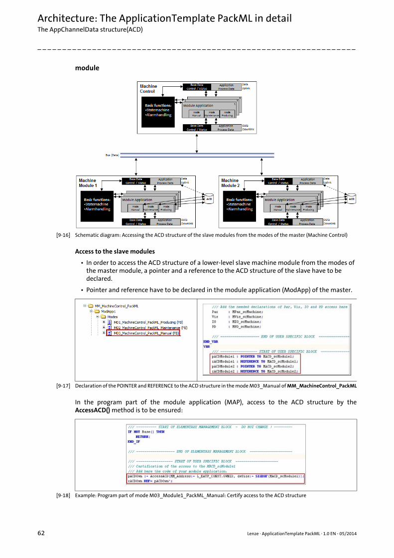
Architecture: The ApplicationTemplate PackML in detailThe AppChannelData structure(ACD)
62 Lenze · ApplicationTemplate PackML · 1.0 EN - 05/2014
_ _ _ _ _ _ _ _ _ _ _ _ _ _ _ _ _ _ _ _ _ _ _ _ _ _ _ _ _ _ _ _ _ _ _ _ _ _ _ _ _ _ _ _ _ _ _ _ _ _ _ _ _ _ _ _ _ _ _ _ _ _ _ _
module
[9-16] Schematic diagram: Accessing the ACD structure of the slave modules from the modes of the master (Machine Control)
Access to the slave modules
• In order to access the ACD structure of a lower-level slave machine module from the modes of the master module, a pointer and a reference to the ACD structure of the slave have to be declared.
• Pointer and reference have to be declared in the module application (ModApp) of the master.
[9-17] Declaration of the POINTER and REFERENCE to the ACD structure in the mode M03_Manual of MM_MachineControl_PackML
In the program part of the module application (MAP), access to the ACD structure by theAccessACD() method is to be ensured:
[9-18] Example: Program part of mode M03_Module1_PackML_Manual: Certify access to the ACD structure
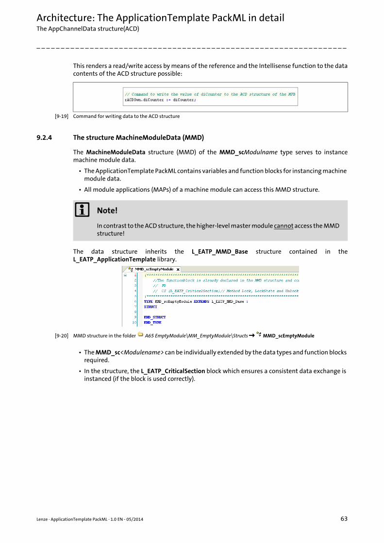
Lenze · ApplicationTemplate PackML · 1.0 EN - 05/2014 63
Architecture: The ApplicationTemplate PackML in detailThe AppChannelData structure(ACD)
_ _ _ _ _ _ _ _ _ _ _ _ _ _ _ _ _ _ _ _ _ _ _ _ _ _ _ _ _ _ _ _ _ _ _ _ _ _ _ _ _ _ _ _ _ _ _ _ _ _ _ _ _ _ _ _ _ _ _ _ _ _ _ _
This renders a read/write access by means of the reference and the Intellisense function to the datacontents of the ACD structure possible:
[9-19] Command for writing data to the ACD structure
9.2.4 The structure MachineModuleData (MMD)
The MachineModuleData structure (MMD) of the MMD_scModulname type serves to instancemachine module data.
• The ApplicationTemplate PackML contains variables and function blocks for instancing machine module data.
• All module applications (MAPs) of a machine module can access this MMD structure.
The data structure inherits the L_EATP_MMD_Base structure contained in theL_EATP_ApplicationTemplate library.
[9-20] MMD structure in the folder A65 EmptyModule\MM_EmptyModule\Structs MMD_scEmptyModule
• The MMD_sc<Modulename> can be individually extended by the data types and function blocks required.
• In the structure, the L_EATP_CriticalSection block which ensures a consistent data exchange is instanced (if the block is used correctly).
Note!
In contrast to the ACD structure, the higher-level master module cannot access the MMD structure!

Architecture: The ApplicationTemplate PackML in detailState machine in detail
64 Lenze · ApplicationTemplate PackML · 1.0 EN - 05/2014
_ _ _ _ _ _ _ _ _ _ _ _ _ _ _ _ _ _ _ _ _ _ _ _ _ _ _ _ _ _ _ _ _ _ _ _ _ _ _ _ _ _ _ _ _ _ _ _ _ _ _ _ _ _ _ _ _ _ _ _ _ _ _ _
Accessing the MMD structure - by means of the module application of the MFB
[9-21] Schematic diagram: Accessing the MMD structure from the module application (MAP) of a machine module (MM_Module)
[9-22] Commands for writing data to the MMD structure
9.3 State machine in detail
The top machine control module MM_MachineControl_PackML is the master module and...
• ...is located at the first/top position in the MachineModuleTree (MMT)
• ...controls the state machine of all lower-level slave machine modules.
The state transitions triggered by the master module have an impact on the lower-level slavemachine modules.
9.3.1 State transitions and conditions - overview
This section describes the single state transitions of the state machine of the ApplicationTemplatePackML.
• IntelliSense function: In each MAP, the "rMMD" is declared which enables the read/write access to the data contents of the MMD structure.

Lenze · ApplicationTemplate PackML · 1.0 EN - 05/2014 65
Architecture: The ApplicationTemplate PackML in detailState machine in detail
_ _ _ _ _ _ _ _ _ _ _ _ _ _ _ _ _ _ _ _ _ _ _ _ _ _ _ _ _ _ _ _ _ _ _ _ _ _ _ _ _ _ _ _ _ _ _ _ _ _ _ _ _ _ _ _ _ _ _ _ _ _ _ _
[9-23] Complete state diagram according to PackML standard
The condition for switching the state transitions is that the result of theCommand_StateBusy(xAllOrSlaves:=TRUE) method is FALSE, except for the transitions "Abort" and"Stop".
• The "Stop" transition enables a transition to the "stopping" state from all areas without Command_StateBusy (xAllOrSlaves:=TRUE) being =FALSE.
• The "Abort" transition enables a transition to the "Aborting" without Command_StateBusy (xAllOrSlaves:=TRUE) being = FALSE.
• All other state transitions can be found in the following section with the related Command_CtrlCmds _xxx. The state transitions in detail: Command_CtrlCmds() method ( 67)
9.3.2 Methods for changing over the state transitions
The following section provides an overview of all methods in the ApplicationTemplate PackML:An overview of the methods ( 91)
Changing over a single transition
[9-24] Example: Changes the transition "Start" from"Idle""Starting".
• Thus, the state machine then is in the active "Starting" state.
• The xCmdChangeRequest value of the method cause a switching of the transition by means of a positive edge.
• As long as one of the slave modules has the xBusy status, a changeover of the state machine is prevented.
Querying the state
[9-25] Example: Enquires the state of all lower-level slave modules and the own module.
Command_CtrlCmd(eCtrlCmd:=L_EATP_CtrlCmd_PackML.Start , xCmdChangeRequest:=TRUE)
Status_StateBusy(xAllOrSlaves:=TRUE)
Architecture: The ApplicationTemplate PackML in detailState machine in detail
66 Lenze · ApplicationTemplate PackML · 1.0 EN - 05/2014
_ _ _ _ _ _ _ _ _ _ _ _ _ _ _ _ _ _ _ _ _ _ _ _ _ _ _ _ _ _ _ _ _ _ _ _ _ _ _ _ _ _ _ _ _ _ _ _ _ _ _ _ _ _ _ _ _ _ _ _ _ _ _ _
• xAllOrSlaves:=TRUE causes to also enquires the own module
• xAllOrSlaves:=FALSE only enquires the lower-level slaves of the module.
Querying the current state
Status_UnitStateCurrent (MM_Address:= L_EATP_CONST.OWNID)
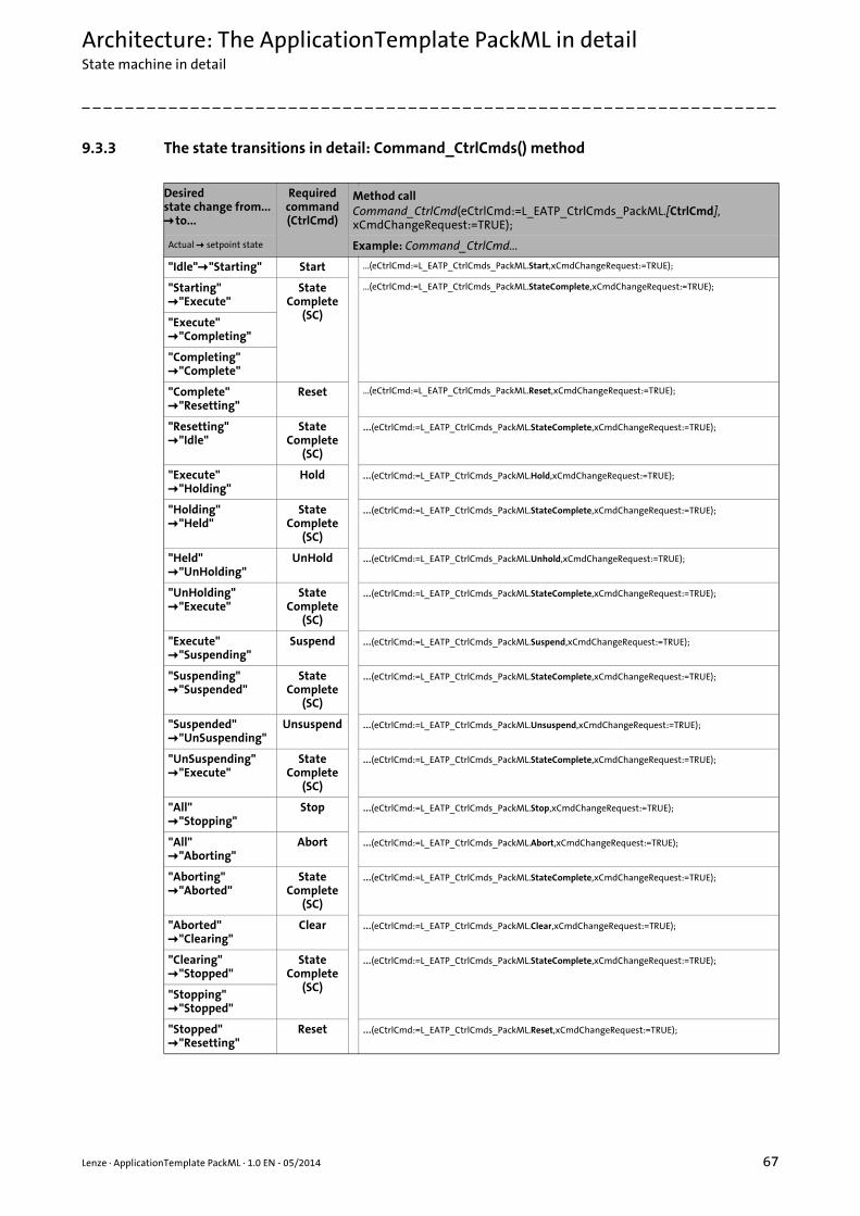
Lenze · ApplicationTemplate PackML · 1.0 EN - 05/2014 67
Architecture: The ApplicationTemplate PackML in detailState machine in detail
_ _ _ _ _ _ _ _ _ _ _ _ _ _ _ _ _ _ _ _ _ _ _ _ _ _ _ _ _ _ _ _ _ _ _ _ _ _ _ _ _ _ _ _ _ _ _ _ _ _ _ _ _ _ _ _ _ _ _ _ _ _ _ _
9.3.3 The state transitions in detail: Command_CtrlCmds() method
Desiredstate change from... to...
Required command(CtrlCmd)
Method callCommand_CtrlCmd(eCtrlCmd:=L_EATP_CtrlCmds_PackML.[CtrlCmd],xCmdChangeRequest:=TRUE);
Actual setpoint state Example: Command_CtrlCmd...
"Idle""Starting" Start ...(eCtrlCmd:=L_EATP_CtrlCmds_PackML.Start,xCmdChangeRequest:=TRUE);
"Starting""Execute"
StateComplete
(SC)
...(eCtrlCmd:=L_EATP_CtrlCmds_PackML.StateComplete,xCmdChangeRequest:=TRUE);
"Execute""Completing"
"Completing""Complete"
"Complete""Resetting"
Reset ...(eCtrlCmd:=L_EATP_CtrlCmds_PackML.Reset,xCmdChangeRequest:=TRUE);
"Resetting""Idle"
StateComplete
(SC)
...(eCtrlCmd:=L_EATP_CtrlCmds_PackML.StateComplete,xCmdChangeRequest:=TRUE);
"Execute""Holding"
Hold ...(eCtrlCmd:=L_EATP_CtrlCmds_PackML.Hold,xCmdChangeRequest:=TRUE);
"Holding""Held"
StateComplete
(SC)
...(eCtrlCmd:=L_EATP_CtrlCmds_PackML.StateComplete,xCmdChangeRequest:=TRUE);
"Held""UnHolding"
UnHold ...(eCtrlCmd:=L_EATP_CtrlCmds_PackML.Unhold,xCmdChangeRequest:=TRUE);
"UnHolding""Execute"
StateComplete
(SC)
...(eCtrlCmd:=L_EATP_CtrlCmds_PackML.StateComplete,xCmdChangeRequest:=TRUE);
"Execute""Suspending"
Suspend ...(eCtrlCmd:=L_EATP_CtrlCmds_PackML.Suspend,xCmdChangeRequest:=TRUE);
"Suspending""Suspended"
StateComplete
(SC)
...(eCtrlCmd:=L_EATP_CtrlCmds_PackML.StateComplete,xCmdChangeRequest:=TRUE);
"Suspended""UnSuspending"
Unsuspend ...(eCtrlCmd:=L_EATP_CtrlCmds_PackML.Unsuspend,xCmdChangeRequest:=TRUE);
"UnSuspending""Execute"
StateComplete
(SC)
...(eCtrlCmd:=L_EATP_CtrlCmds_PackML.StateComplete,xCmdChangeRequest:=TRUE);
"All""Stopping"
Stop ...(eCtrlCmd:=L_EATP_CtrlCmds_PackML.Stop,xCmdChangeRequest:=TRUE);
"All""Aborting"
Abort ...(eCtrlCmd:=L_EATP_CtrlCmds_PackML.Abort,xCmdChangeRequest:=TRUE);
"Aborting""Aborted"
StateComplete
(SC)
...(eCtrlCmd:=L_EATP_CtrlCmds_PackML.StateComplete,xCmdChangeRequest:=TRUE);
"Aborted""Clearing"
Clear ...(eCtrlCmd:=L_EATP_CtrlCmds_PackML.Clear,xCmdChangeRequest:=TRUE);
"Clearing""Stopped"
StateComplete
(SC)
...(eCtrlCmd:=L_EATP_CtrlCmds_PackML.StateComplete,xCmdChangeRequest:=TRUE);
"Stopping""Stopped"
"Stopped""Resetting"
Reset ...(eCtrlCmd:=L_EATP_CtrlCmds_PackML.Reset,xCmdChangeRequest:=TRUE);
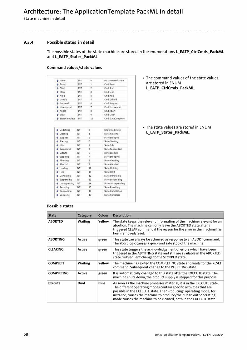
Architecture: The ApplicationTemplate PackML in detailState machine in detail
68 Lenze · ApplicationTemplate PackML · 1.0 EN - 05/2014
_ _ _ _ _ _ _ _ _ _ _ _ _ _ _ _ _ _ _ _ _ _ _ _ _ _ _ _ _ _ _ _ _ _ _ _ _ _ _ _ _ _ _ _ _ _ _ _ _ _ _ _ _ _ _ _ _ _ _ _ _ _ _ _
9.3.4 Possible states in detail
The possible states of the state machine are stored in the enumerations L_EATP_CtrlCmds_PackMLand L_EATP_States_PackML.
Command values/state values
Possible states
• The command values of the state values are stored in ENUM L_EATP_CtrlCmds_PackML.
• The state values are stored in ENUM L_EATP_States_PackML.
State Category Colour Description
ABORTED Waiting Yellow The state keeps the relevant information of the machine relevant for an abortion. The machine can only leave the ABORTED state after a triggered CLEAR command if the reason for the error in the machine has been removed/reset.
ABORTING Active green This state can always be achieved as response to an ABORT command. The abort logic causes a quick and safe stop of the machine.
CLEARING Active green This state triggers the acknowledgement of errors which have been triggered in the ABORTING state and still are available in the ABORTED state. Subsequent change to the STOPPED state.
COMPLETE Waiting Yellow The machine has exited the COMPLETING state and waits for the RESET command. Subsequent change to the RESETTING state.
COMPLETING Active green It is automatically changed to this state after the EXECUTE state. The machine shuts down, the product supply is stopped for this purpose.
Execute Dual Blue As soon as the machine processes material, it is in the EXECUTE state. The different operating modes contain specific activities that are possible in the EXECUTE state. The "Producing" operating mode, for instance, causes the machine to produce/the "Clean out" operating mode causes the machine to be cleaned, both in the EXECUTE state.

Lenze · ApplicationTemplate PackML · 1.0 EN - 05/2014 69
Architecture: The ApplicationTemplate PackML in detailState machine in detail
_ _ _ _ _ _ _ _ _ _ _ _ _ _ _ _ _ _ _ _ _ _ _ _ _ _ _ _ _ _ _ _ _ _ _ _ _ _ _ _ _ _ _ _ _ _ _ _ _ _ _ _ _ _ _ _ _ _ _ _ _ _ _ _
HELD Waiting Yellow This state is reached as described for the HOLDING state. In the HELD state, the machine is stopped either by a complete stop or by a continuous "dry running".
• As soon as the INTERNAL machine state changes/the operator triggers the UNHOLD command, the machine changes to the UNHOLDING state.
• Usually, the Performance Management/OEE system considers the HELD state (waiting for the entry of the operator) as "not available".
HOLDING Active green This state is reached if INTERNAL machine states causes the production of the machine to stop. This means that the machine leaves the EXECUTE state due to an INTERNAL trigger/state.
• Usually, the HOLDING state takes place in case of regularly occurring machine states that require an action of the operator in order that the machine is able to continue the production.
• The HOLDING state can be automatically or manually triggered/retracted again by the operator. The regular filling of material, for instance, needs an action of the operator, as the filling of adhesive dispensers or cardboard storages. This may be required if due to the mechanical construction of the machine a certain action is only possible when the machine is stopped.
• Filling up material is a regular working sequence in the production process. Thus, it is an integral part of the machine. (If it was an external part, this subfunction would bring the machine to a standstill by ABORTING/STOPPING). Usually the machine is stopped in a controlled manner in the HOLDING state and then changed to the HELD state.
• In order to restart the machine in a controlled manner after the HELD state, all relevant process setpoints/return states of the procedures have to be saved that are available at the time of the HOLD command in the machine control.
IDLE Waiting Yellow This state indicates that the RESETTING has been completed. The IDLE state keeps the current state of the machines that have been reached during RESETTING state and executes the requested operations.
RESETTING Active green This state is active after the RESET command has been triggered in the RESET/STOPPED state.
• Error and stop events are reset.• Usually, the RESETTING state safety appliances. The machine changes
to the IDLE state to wait for the START command. This ensures that the machine does not carry out any dangerous movements in this state.
STARTING Active green This state comprises the steps required for starting the machine and is caused by a START command. After a successful start: Change to the EXECUTE state.
STOPPED Waiting Yellow After the STOPPING state has been left, the machine is switched on and at standstill. The communication with other systems is fully functional. The RESET command triggers the change to the RESETTING state.
stopping Active green This state carries out steps that stop the machine in a controlled manner, see STOPPED state. The machine cannot be started again until a restart is executed.
SUSPENDED Waiting Yellow This state is reached as described for the SUSPENDING state. In this state, the machine stops either by a complete stop or by continuously moving without producing until the external state has normalised.
• Typically, the state changes from SUSPENDED to UNSUSPENDING without the operator having to trigger a command.
• Usually, the Performance Management/OEE system considers the SUSPENDED state (blockade/supply shortfall) as "available".
State Category Colour Description
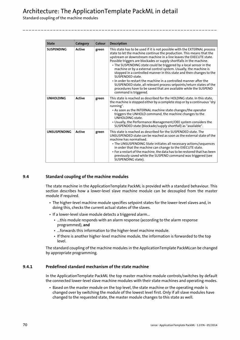
Architecture: The ApplicationTemplate PackML in detailStandard coupling of the machine modules
70 Lenze · ApplicationTemplate PackML · 1.0 EN - 05/2014
_ _ _ _ _ _ _ _ _ _ _ _ _ _ _ _ _ _ _ _ _ _ _ _ _ _ _ _ _ _ _ _ _ _ _ _ _ _ _ _ _ _ _ _ _ _ _ _ _ _ _ _ _ _ _ _ _ _ _ _ _ _ _ _
9.4 Standard coupling of the machine modules
The state machine in the ApplicationTemplate PackML is provided with a standard behaviour. Thissection describes how a lower-level slave machine module can be decoupled from the mastermodule if required.
• The higher-level machine module specifies setpoint states for the lower-level slaves and, in doing this, checks the current actual states of the slaves.
• If a lower-level slave module detects a triggered alarm...• ...this module responds with an alarm response (according to the alarm response
programmed), and• ...forwards this information to the higher-level machine module.• If there is another higher-level machine module, the information is forwarded to the top
level.
The standard coupling of the machine modules in the ApplicationTemplate PackMLcan be changedby appropriate programming.
9.4.1 Predefined standard mechanism of the state machine
In the ApplicationTemplate PackML the top master machine module controls/switches by defaultthe connected lower-level slave machine modules with their state machines and operating modes.
• Based on the master module on the top level, the state machine or the operating mode is changed over by switching the module of the lowest level first. Only if all slave modules have changed to the requested state, the master module changes to this state as well.
SUSPENDING Active green This state has to be used if it is not possible with the EXTERNAL process state to let the machine continue the production. This means that the upstream or downstream machine in a line leaves the EXECUTE state. Possible triggers are blockades or supply shortfalls in the machine.
• The SUSPENDING state could be triggered by a local sensor in the machine or by a external control system. Usually, the machine is stopped in a controlled manner in this state and then changes to the SUSPENDED state.
• In order to restart the machine in a controlled manner after the SUSPENDED state, all relevant process setpoints/return states of the procedures have to be saved that are available while the SUSPEND command is triggered.
UNHOLDING Active green This state is reached as described for the HOLDING state. In this state, the machine is stopped either by a complete stop or by a continuous "dry running".
• As soon as the INTERNAL machine state changes/the operator triggers the UNHOLD command, the machine changes to the UNHOLDING state.
• Usually, the Performance Management/OEE system considers the SUSPENDED state (blockade/supply shortfall) as "available".
UNSUSPENDING Active green This state is reached as described for the SUSPENDED state. The UNSUSPENDED state can be reached as soon as the external state of the machine has normalised.
• The UNSUSPENDING State initiates all necessary actions/sequences in order that the machine can change to the EXECUTE state.
• For a restart of the machine, the data has to be restored that has been previously saved while the SUSPEND command was triggered (see SUSPENDING state).
State Category Colour Description

Lenze · ApplicationTemplate PackML · 1.0 EN - 05/2014 71
Architecture: The ApplicationTemplate PackML in detailInfluencing state transitions
_ _ _ _ _ _ _ _ _ _ _ _ _ _ _ _ _ _ _ _ _ _ _ _ _ _ _ _ _ _ _ _ _ _ _ _ _ _ _ _ _ _ _ _ _ _ _ _ _ _ _ _ _ _ _ _ _ _ _ _ _ _ _ _
• The standard behaviour also includes the forwarding of all alarm reactions of the slave modules to the master.
The standard behaviour of the MMT can be changed by decoupling single modules or bydeactivating single machine modules via:
[9-26] Deactivating/decoupling a module, "MM_Address" refers to the address of the module, here the own module.
9.4.1.1 The Command_DisableModule method: Decoupling modules
The Command_DisableModule method enables the slave module to be decoupled by the master.
• This decouples the state machine and mode of the decoupled module from the higher-level master: The machine module keeps the current state and the operating mode and the operating mode. After the corresponding module is decoupled ("disabled"), the state machines of the master and the decoupled module can be operated independently of each other.
• From the time of decoupling, the decoupled module is the master for the slave modules that are subordinated to this module.
9.4.1.2 Renewed coupling of machine modules
In order to couple the module to the master again, the different states/operating modes of the statemachines of master and slave have to be adapted. In order to enquire the current state and theoperating mode of the master, the methods Status_MasterUnitModeCurrent andStatus_MasterUnitStateCurrent have to be used.
• The L_EATP_CtrlCmds_PackML command and the Command_UnitMode method adjust the state machine and the operating mode of the decoupled module with the master module.
• After the master and slave module are in the same state and operating mode, the module can be coupled using the Command_DisableModule method.
More information on the methods: An overview of the status methods: Status_xxx ( 94)
The Command_SendAlarmReactionIfDisabled method: Alarm reaction to the master
Decoupling a module with the Command_DisableModule method deactivates the standardforwarding of the alarm reaction to the master module.
• In order to transmit the reaction type of a deactivated module to the master, the Command_SendAlarmReactionIfDisabled method has to be used and the respective reaction type has to be set to "TRUE".
Example: Parameter "xSendFault:=TRUE" to only forward the reaction type Fault to the master.
More information on the methods: An overview of the command methods: Command_xxx ( 92)
9.5 Influencing state transitions
The xStateBusy variable can prevent a changeover of a state transition.
Command_DisableModule(MM_Address:= L_EATP_CONST.OWNID, xValue:=TRUE);
Command_SendAlarmReactionIfDisabled(MM_Address:=L_EATP_CONST.OWNID,xSendSystemFault :=FALSE,xSendAbort:=FALSE,xSendStop:=FALSE,xSendFault:=TRUE,xSendWarning:=FALSE);

Architecture: The ApplicationTemplate PackML in detailStater machine: Query examples
72 Lenze · ApplicationTemplate PackML · 1.0 EN - 05/2014
_ _ _ _ _ _ _ _ _ _ _ _ _ _ _ _ _ _ _ _ _ _ _ _ _ _ _ _ _ _ _ _ _ _ _ _ _ _ _ _ _ _ _ _ _ _ _ _ _ _ _ _ _ _ _ _ _ _ _ _ _ _ _ _
• As long as a state of a slave module has xStateBusy= TRUE , the changeover of the state machine is prevented. An exception is the triggering of the commands "Abort" or "Stop".
By default, the module is set to the respective state with the command in the first cycle of state .
If all tasks are done in this state, xStateBusy can be reset again to enable the changeover toanother state.
The following program line enquires the state:
"xAllOrSlaves:=TRUE" also enquires the own module, "xAllOrSlaves:=FALSE only the slaves of themodule.
9.6 Stater machine: Query examples
This section shows (by the use of program examples) how...
• ...to access the state machine.
• ...to query the states.
Command_StateBusy(xStateBusy:= TRUE)
Status_StateBusy(xAllOrSlaves:=TRUE)
Objective/call Example
Querying the current state
• IF condition• Subordinated module status
enquiry by method(example: Slave, address = 1)
IF Status_UnitStateCurrent (MM_Address:= 1)= L_EATP_States_PackML.Execute THEN// Do something if Statemachine is in state EXECUTEEND_IF
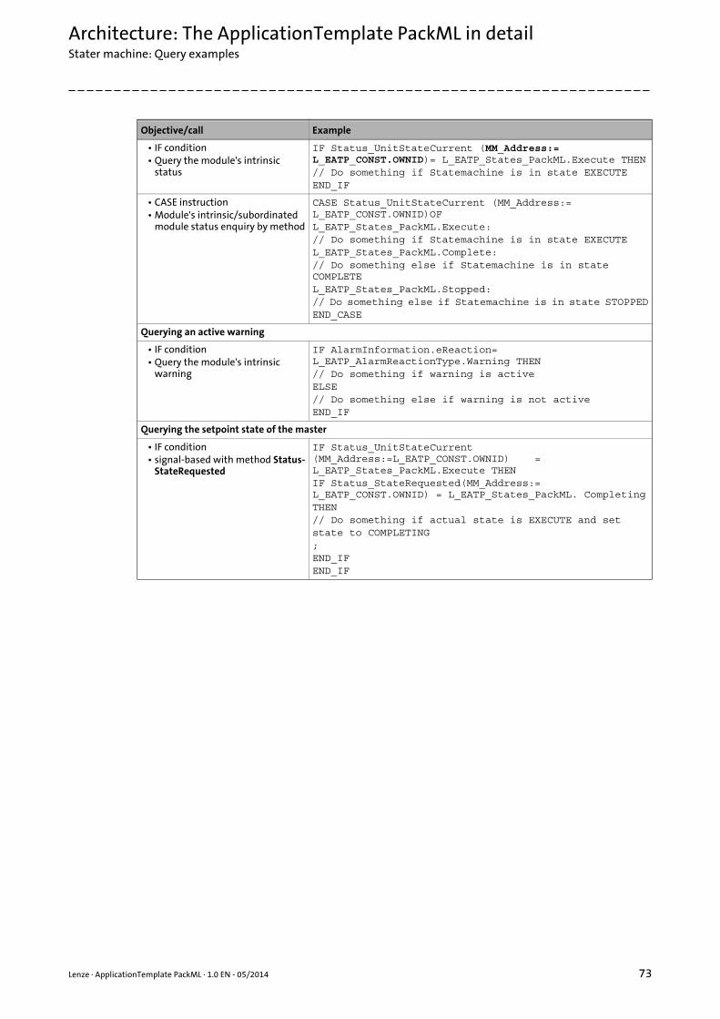
Lenze · ApplicationTemplate PackML · 1.0 EN - 05/2014 73
Architecture: The ApplicationTemplate PackML in detailStater machine: Query examples
_ _ _ _ _ _ _ _ _ _ _ _ _ _ _ _ _ _ _ _ _ _ _ _ _ _ _ _ _ _ _ _ _ _ _ _ _ _ _ _ _ _ _ _ _ _ _ _ _ _ _ _ _ _ _ _ _ _ _ _ _ _ _ _
• IF condition• Query the module's intrinsic
status
IF Status_UnitStateCurrent (MM_Address:= L_EATP_CONST.OWNID)= L_EATP_States_PackML.Execute THEN// Do something if Statemachine is in state EXECUTEEND_IF
• CASE instruction• Module's intrinsic/subordinated
module status enquiry by method
CASE Status_UnitStateCurrent (MM_Address:= L_EATP_CONST.OWNID)OF L_EATP_States_PackML.Execute:// Do something if Statemachine is in state EXECUTEL_EATP_States_PackML.Complete:// Do something else if Statemachine is in state COMPLETEL_EATP_States_PackML.Stopped:// Do something else if Statemachine is in state STOPPEDEND_CASE
Querying an active warning
• IF condition• Query the module's intrinsic
warning
IF AlarmInformation.eReaction= L_EATP_AlarmReactionType.Warning THEN// Do something if warning is activeELSE// Do something else if warning is not activeEND_IF
Querying the setpoint state of the master
• IF condition• signal-based with method Status-
StateRequested
IF Status_UnitStateCurrent (MM_Address:=L_EATP_CONST.OWNID) = L_EATP_States_PackML.Execute THENIF Status_StateRequested(MM_Address:= L_EATP_CONST.OWNID) = L_EATP_States_PackML. CompletingTHEN// Do something if actual state is EXECUTE and setstate to COMPLETING;END_IFEND_IF
Objective/call Example
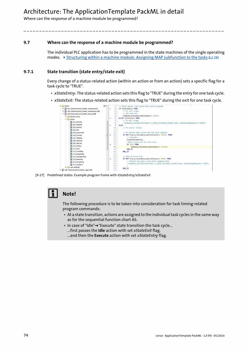
Architecture: The ApplicationTemplate PackML in detailWhere can the response of a machine module be programmed?
74 Lenze · ApplicationTemplate PackML · 1.0 EN - 05/2014
_ _ _ _ _ _ _ _ _ _ _ _ _ _ _ _ _ _ _ _ _ _ _ _ _ _ _ _ _ _ _ _ _ _ _ _ _ _ _ _ _ _ _ _ _ _ _ _ _ _ _ _ _ _ _ _ _ _ _ _ _ _ _ _
9.7 Where can the response of a machine module be programmed?
The individual PLC application has to be programmed in the state machines of the single operatingmodes. Structuring within a machine module: Assigning MAP subfunction to the tasks ( 28)
9.7.1 State transition (state entry/state exit)
Every change of a status-related action (within an action or from an action) sets a specific flag for atask cycle to "TRUE".
• xStateEntry: The status-related action sets this flag to "TRUE" during the entry for one task cycle.
• xStateExit: The status-related action sets this flag to "TRUE" during the exit for one task cycle.
[9-27] Predefined states: Example program frame with xStateEntry/xStateExit
Note!
The following procedure is to be taken into consideration for task timing-related program commands:• At a state transition, actions are assigned to the individual task cycles in the same way
as for the sequential function chart AS.• In case of "Idle""Execute" state transition the task cycle...
...first passes the Idle action with set xStateExit flag.
...and then the Execute action with set xStateEntry flag.
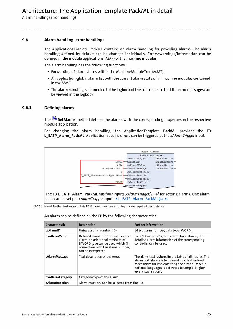
Lenze · ApplicationTemplate PackML · 1.0 EN - 05/2014 75
Architecture: The ApplicationTemplate PackML in detailAlarm handling (error handling)
_ _ _ _ _ _ _ _ _ _ _ _ _ _ _ _ _ _ _ _ _ _ _ _ _ _ _ _ _ _ _ _ _ _ _ _ _ _ _ _ _ _ _ _ _ _ _ _ _ _ _ _ _ _ _ _ _ _ _ _ _ _ _ _
9.8 Alarm handling (error handling)
The ApplicationTemplate PackML contains an alarm handling for providing alarms. The alarmhandling defined by default can be changed individually. Errors/warnings/information can bedefined in the module applications (MAP) of the machine modules.
The alarm handling has the following functions:
• Forwarding of alarm states within the MachineModuleTree (MMT).
• An application-global alarm list with the current alarm state of all machine modules contained in the MMT.
• The alarm handling is connected to the logbook of the controller, so that the error messages can be viewed in the logbook.
9.8.1 Defining alarms
The SetAlarms method defines the alarms with the corresponding properties in the respectivemodule application.
For changing the alarm handling, the ApplicationTemplate PackML provides the FBL_EATP_Alarm_PackML. Application-specific errors can be triggered at the xAlarmTrigger input.
[9-28] Insert further instances of this FB if more than four error inputs are required per instance.
An alarm can be defined on the FB by the following characteristics:
The FB L_EATP_Alarm_PackML has four inputs xAlarmTrigger[1...4] for setting alarms. One alarmeach can be set per xAlarmTrigger input. L_EATP_Alarm_PackML ( 98)
Characteristic Description Further information
wAlarmID Unique alarm number (ID). 16 bit alarm number, data type: WORD.
dwAlarmValue Detailed alarm information: For each alarm, an additional attribute of DWORD type can be used which (in connection with the alarm number) can be interpreted.
For a "Drive Error" group alarm, for instance, the detailed alarm information of the corresponding controller can be used.
sAlarmMessage Text description of the error. The alarm text is stored in the table of attributes. The alarm text always is to be used if no higher-level mechanism for implementing the error number in national languages is activated (example: Higher-level visualisation).
dwAlarmCategory Category/type of the alarm.
eAlarmReaction Alarm reaction: Can be selected from the list.

Architecture: The ApplicationTemplate PackML in detailAlarm handling (error handling)
76 Lenze · ApplicationTemplate PackML · 1.0 EN - 05/2014
_ _ _ _ _ _ _ _ _ _ _ _ _ _ _ _ _ _ _ _ _ _ _ _ _ _ _ _ _ _ _ _ _ _ _ _ _ _ _ _ _ _ _ _ _ _ _ _ _ _ _ _ _ _ _ _ _ _ _ _ _ _ _ _
9.8.2 Acknowledging alarms
Acknowledging alarms deletes all messages/causes defined as subject to acknowledgement fromthe Alarm List. The acknowledgement of alarms can be activated by means of the followingprocedures:
1. Permanent activation: Within the module application via the following program command:
2. Activation for one cycle: Via the Command_AlarmQuit method, rising edge FALSETRUE. The method sets the xQuitErrors input to TRUE for one cycle.
If multiple alarms occur, they cannot be acknowledged individually. Further information:L_EATP_ModuleErrorHandler_PackML ( 103)
9.8.3 Acknowledging alarms: Response in the machine module
The xErrorQuitActive output on the L_EATP_ModuleErrorHandler_PackML block can be used withina module application to acknowledge alarms on an integrated function block.
Defining alarms - standard procedure
dwAlarmPriority Assign priority for alarms of the same error reaction type.
xAlarmAckNeeded Acknowledgement behaviour: Information (yes/no) stating whether the alarm tripped is to be acknowledged.
The acknowledgement behaviour cannotbe changed for all alarm reaction types.
Characteristic Description Further information
ErrorHandler.xQuitErrors := TRUE; //error acknowledgement active as long as value = TRUE
• The SetAlarms is to be extended by one function block.
• The MAP_EmptyModul_App1 FB has to be extended by the corresponding declaration.

Lenze · ApplicationTemplate PackML · 1.0 EN - 05/2014 77
Architecture: The ApplicationTemplate PackML in detailAlarm handling (error handling)
_ _ _ _ _ _ _ _ _ _ _ _ _ _ _ _ _ _ _ _ _ _ _ _ _ _ _ _ _ _ _ _ _ _ _ _ _ _ _ _ _ _ _ _ _ _ _ _ _ _ _ _ _ _ _ _ _ _ _ _ _ _ _ _
• The xAlarmTrigger[1...4] method has to be connected to the module application.
• Assign the corresponding parameter to the respective alarm input:• Number,• text,• priority,• category,• Acknowledgement response
• More information: L_EATP_Alarm_PackML ( 98)
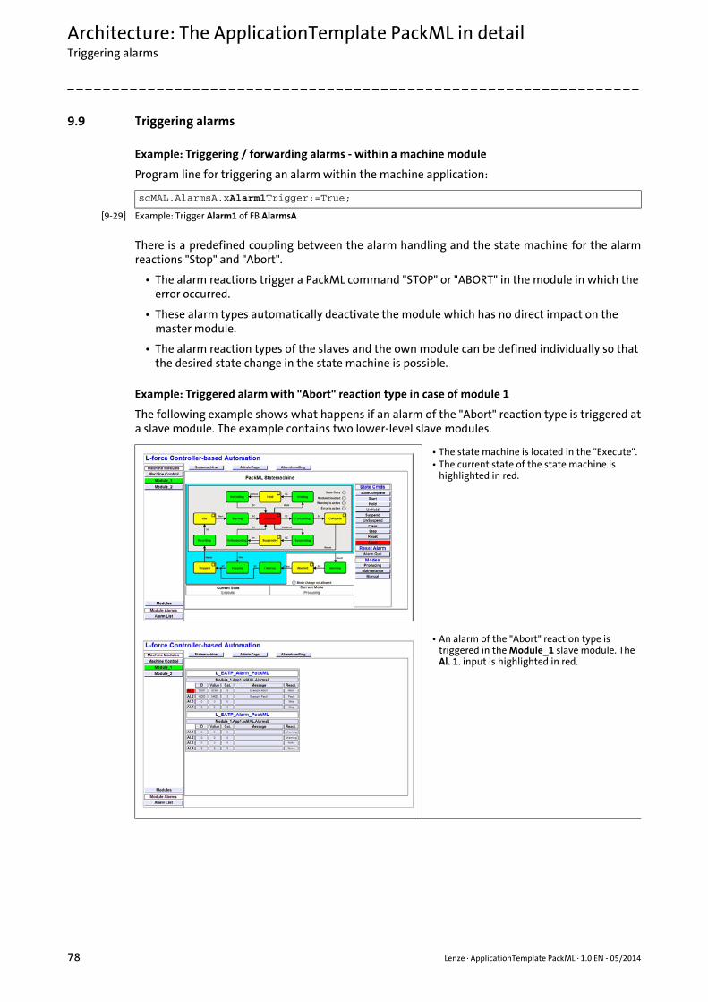
Architecture: The ApplicationTemplate PackML in detailTriggering alarms
78 Lenze · ApplicationTemplate PackML · 1.0 EN - 05/2014
_ _ _ _ _ _ _ _ _ _ _ _ _ _ _ _ _ _ _ _ _ _ _ _ _ _ _ _ _ _ _ _ _ _ _ _ _ _ _ _ _ _ _ _ _ _ _ _ _ _ _ _ _ _ _ _ _ _ _ _ _ _ _ _
9.9 Triggering alarms
Example: Triggering / forwarding alarms - within a machine module
Program line for triggering an alarm within the machine application:
[9-29] Example: Trigger Alarm1 of FB AlarmsA
There is a predefined coupling between the alarm handling and the state machine for the alarmreactions "Stop" and "Abort".
• The alarm reactions trigger a PackML command "STOP" or "ABORT" in the module in which the error occurred.
• These alarm types automatically deactivate the module which has no direct impact on the master module.
• The alarm reaction types of the slaves and the own module can be defined individually so that the desired state change in the state machine is possible.
Example: Triggered alarm with "Abort" reaction type in case of module 1
The following example shows what happens if an alarm of the "Abort" reaction type is triggered ata slave module. The example contains two lower-level slave modules.
scMAL.AlarmsA.xAlarm1Trigger:=True;
• The state machine is located in the "Execute".• The current state of the state machine is
highlighted in red.
• An alarm of the "Abort" reaction type is triggered in the Module_1 slave module. The Al. 1. input is highlighted in red.

Lenze · ApplicationTemplate PackML · 1.0 EN - 05/2014 79
Architecture: The ApplicationTemplate PackML in detailCentral management of alarms
_ _ _ _ _ _ _ _ _ _ _ _ _ _ _ _ _ _ _ _ _ _ _ _ _ _ _ _ _ _ _ _ _ _ _ _ _ _ _ _ _ _ _ _ _ _ _ _ _ _ _ _ _ _ _ _ _ _ _ _ _ _ _ _
In order to couple the Modul_1 slave module to the master again, first the reason for the alarm hasto be removed.
• By means of a procedure, both state machines of master and slave module have to be synchronised.
• The deactivated slave module has to be coupled again to the state machine of the master module using the Command_DisableModule method. Renewed coupling of machine modules ( 71)
9.10 Central management of alarms
The alarm handling transmits all alarms that occur in the machine modules to the global Alarm List.
• The state machine of the Modul_1 slave module is decoupled automatically from the master module. "Module Disabled" is highlighted in red.
• The state machine changes to the "ABORTING" state.
• The Machine Control master module remains unchanged in the "EXECUTE" state.
• The machine modules forward the messages to the Alarm List Handler.
• All current alarms are visible in the global Alarm List.
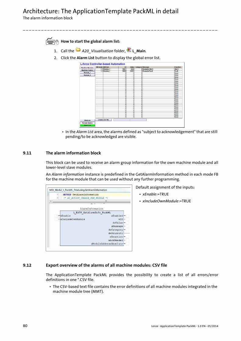
Architecture: The ApplicationTemplate PackML in detailThe alarm information block
80 Lenze · ApplicationTemplate PackML · 1.0 EN - 05/2014
_ _ _ _ _ _ _ _ _ _ _ _ _ _ _ _ _ _ _ _ _ _ _ _ _ _ _ _ _ _ _ _ _ _ _ _ _ _ _ _ _ _ _ _ _ _ _ _ _ _ _ _ _ _ _ _ _ _ _ _ _ _ _ _
How to start the global alarm list:
1. Call the A20_Visualisation folder, L_Main.
2. Click the Alarm List button to display the global error list.
• In the Alarm List area, the alarms defined as "subject to acknowledgement" that are still pending/to be acknowledged are visible.
9.11 The alarm information block
This block can be used to receive an alarm group information for the own machine module and alllower-level slave modules.
An Alarm information instance is predefined in the GetAlarmInformation method in each mode FBfor the machine module that can be used without any further programming.
9.12 Export overview of the alarms of all machine modules: CSV file
The ApplicationTemplate PackML provides the possibility to create a list of all errors/errordefinitions in one *.CSV file.
• The CSV-based text file contains the error definitions of all machine modules integrated in the machine module tree (MMT).
Default assignment of the inputs:
• xEnable:=TRUE
• xIncludeOwnModule:=TRUE
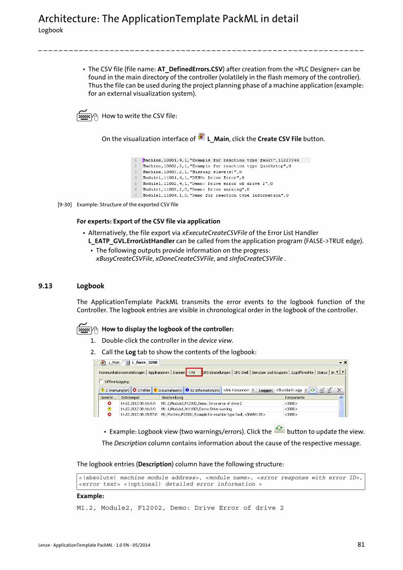
Lenze · ApplicationTemplate PackML · 1.0 EN - 05/2014 81
Architecture: The ApplicationTemplate PackML in detailLogbook
_ _ _ _ _ _ _ _ _ _ _ _ _ _ _ _ _ _ _ _ _ _ _ _ _ _ _ _ _ _ _ _ _ _ _ _ _ _ _ _ _ _ _ _ _ _ _ _ _ _ _ _ _ _ _ _ _ _ _ _ _ _ _ _
• The CSV file (file name: AT_DefinedErrors.CSV) after creation from the »PLC Designer« can be found in the main directory of the controller (volatilely in the flash memory of the controller). Thus the file can be used during the project planning phase of a machine application (example: for an external visualization system).
How to write the CSV file:
On the visualization interface of L_Main, click the Create CSV File button.
[9-30] Example: Structure of the exported CSV file
For experts: Export of the CSV file via application
• Alternatively, the file export via xExecuteCreateCSVFile of the Error List Handler L_EATP_GVL.ErrorListHandler can be called from the application program (FALSE->TRUE edge).• The following outputs provide information on the progress:
xBusyCreateCSVFile, xDoneCreateCSVFile, and sInfoCreateCSVFile .
9.13 Logbook
The ApplicationTemplate PackML transmits the error events to the logbook function of theController. The logbook entries are visible in chronological order in the logbook of the controller.
How to display the logbook of the controller:
1. Double-click the controller in the device view.
2. Call the Log tab to show the contents of the logbook:
• Example: Logbook view (two warnings/errors). Click the button to update the view.
The Description column contains information about the cause of the respective message.
The logbook entries (Description) column have the following structure:
Example:
M1.2, Module2, F12002, Demo: Drive Error of drive 2
<(absolute) machine module address>, <module name>, <error response with error ID>,<error text> <(optional) detailed error information >

Architecture: The ApplicationTemplate PackML in detailModule diagnostics
82 Lenze · ApplicationTemplate PackML · 1.0 EN - 05/2014
_ _ _ _ _ _ _ _ _ _ _ _ _ _ _ _ _ _ _ _ _ _ _ _ _ _ _ _ _ _ _ _ _ _ _ _ _ _ _ _ _ _ _ _ _ _ _ _ _ _ _ _ _ _ _ _ _ _ _ _ _ _ _ _
9.14 Module diagnostics
For diagnosing the modules, the ApplicationTemplate PackML provides a visualisation.
• The Modules button calls the detailed view for the machine modules.
• Click the desired machine module to show the respective status and further details.
• The visualization for module diagnostics is provided as a separate visualization L_EATP_VisModuleList (for instance for own visualization processes).
9.15 Multitasking
The ApplicationTemplate PackML is able to multitask. The following tasks are defined:
• In the A11_ModuleAppCalls folder, the respective module applications can be assigned to the corresponding task.• ModuleAppCalls (MAC) are the calls of a module application (MAP) by the associated
machine modules (MM) of the corresponding task.
Element Source
M1.2 Absolute ID of the machine module
Module2 Name of the machine module
F12002 Error ID, response type: error
Demo: Drive Error of drive 2 Error text
Task level Priority Type Cycle time(bold = default value)
Task_High High cyclic Short (1, 2, 4 ms)
Task_Mid Medium cyclic Medium (4, 6, 8, 16 ms)
Task_Free Low Unsolicited Unsolicited
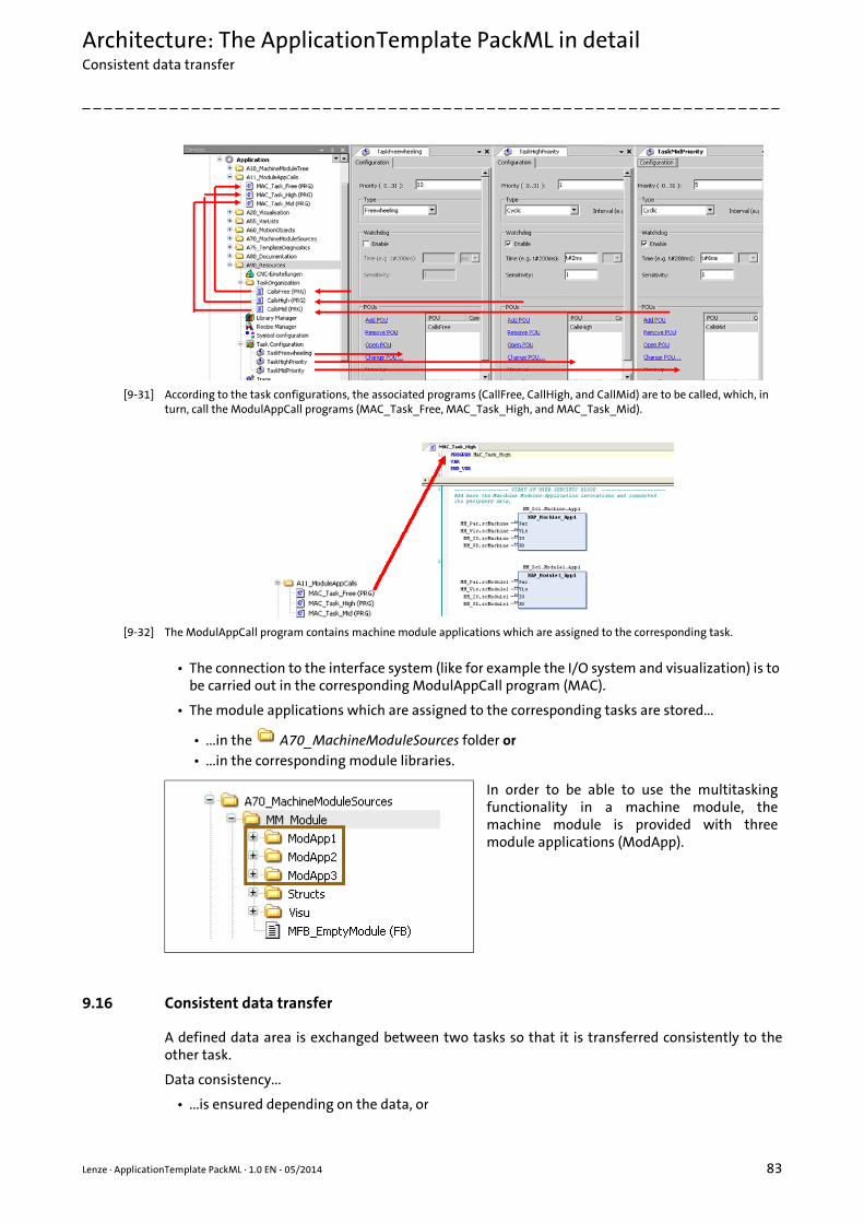
Lenze · ApplicationTemplate PackML · 1.0 EN - 05/2014 83
Architecture: The ApplicationTemplate PackML in detailConsistent data transfer
_ _ _ _ _ _ _ _ _ _ _ _ _ _ _ _ _ _ _ _ _ _ _ _ _ _ _ _ _ _ _ _ _ _ _ _ _ _ _ _ _ _ _ _ _ _ _ _ _ _ _ _ _ _ _ _ _ _ _ _ _ _ _ _
[9-31] According to the task configurations, the associated programs (CallFree, CallHigh, and CallMid) are to be called, which, in turn, call the ModulAppCall programs (MAC_Task_Free, MAC_Task_High, and MAC_Task_Mid).
[9-32] The ModulAppCall program contains machine module applications which are assigned to the corresponding task.
• The connection to the interface system (like for example the I/O system and visualization) is to be carried out in the corresponding ModulAppCall program (MAC).
• The module applications which are assigned to the corresponding tasks are stored...
• ...in the A70_MachineModuleSources folder or• ...in the corresponding module libraries.
9.16 Consistent data transfer
A defined data area is exchanged between two tasks so that it is transferred consistently to theother task.
Data consistency...
• ...is ensured depending on the data, or
In order to be able to use the multitaskingfunctionality in a machine module, themachine module is provided with threemodule applications (ModApp).

Architecture: The ApplicationTemplate PackML in detailConsistent data transfer
84 Lenze · ApplicationTemplate PackML · 1.0 EN - 05/2014
_ _ _ _ _ _ _ _ _ _ _ _ _ _ _ _ _ _ _ _ _ _ _ _ _ _ _ _ _ _ _ _ _ _ _ _ _ _ _ _ _ _ _ _ _ _ _ _ _ _ _ _ _ _ _ _ _ _ _ _ _ _ _ _
• ...to be ensured for specific application cases. Depending on the application case, proceed as follows:
Reserving/inhibiting data areas of the AppChannelData(ACD) structure
The ACD structure contains an L_EATP_CriticalSection block which, by means of the followingmethods, ensures the data consistency of real time-critical data.
• If several blocks are required, further instances of the block can be use in the ACD structure.
1. Before the data area to be transmitted can be accessed consistently, the Lock() method has to be called in a task. The Lock() method returns a BOOL value if...• ...another task has already called the method ("TRUE").• ...no task has called the method yet ("FALSE").
Application case Data element/data type Description
Data consistency within individual data elements
IntegerINT
DINT
Direct access is permissible.
Bit fieldsWORD
DWORD
Data consistency within one data element
Floating pointLREAL
When the controller is used, data consistency of an LREAL variable is ensured.
Data consistency for more than one data element
The data areas have to be...• ...inhibited for others tasks before
the first access, using the Lock() method.
• ...re-enabled after the last access, using the Unlock() method.
Method Function
Lock() Reserve data area of the ACD structure.
Unlock() Enable reserved data of the ACD structure.
LockState() Query locked status of a data area.
Note!
Avoiding performance loss
Avoid inhibiting real time-critical data of the ACD structure by several MAPs within the same machine module by the CriticalSection.• Reserve an individual area for every MAP for real time-critical data in the ACD
structure, in order to avoid that the module application (MAP) of a low-priority task (Task_Mid) slows down the MAP of a higher-priority task (Task_High).
Note!
A task may only use the data area (reading or writing) if the appChannelLock() method has returned the TRUE value.
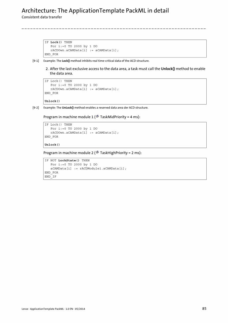
Lenze · ApplicationTemplate PackML · 1.0 EN - 05/2014 85
Architecture: The ApplicationTemplate PackML in detailConsistent data transfer
_ _ _ _ _ _ _ _ _ _ _ _ _ _ _ _ _ _ _ _ _ _ _ _ _ _ _ _ _ _ _ _ _ _ _ _ _ _ _ _ _ _ _ _ _ _ _ _ _ _ _ _ _ _ _ _ _ _ _ _ _ _ _ _
[9-1] Example: The Lock() method inhibits real time-critical data of the ACD structure.
2. After the last exclusive access to the data area, a task must call the Unlock() method to enable the data area.
[9-2] Example: The UnLock() method enables a reserved data area der ACD structure.
Program in machine module 1 ( TaskMidPriority = 4 ms):
Program in machine module 2 ( TaskHighPriority = 2 ms):
IF Lock() THEN For i:=0 TO 2000 by 1 DO rACDOwn.aCAMData[i] := aCAMData[i];END_FOR
IF Lock() THEN For i:=0 TO 2000 by 1 DO rACDOwn.aCAMData[i] := aCAMData[i];END_FOR
Unlock()
IF Lock() THEN For i:=0 TO 2000 by 1 DO rACDOwn.aCAMData[i] := aCAMData[i];END_FOR
Unlock()
IF NOT LockState() THEN For i:=0 TO 2000 by 1 DO aCAMData[i] := rACDModule1.aCAMData[i];END_FOREND_IF
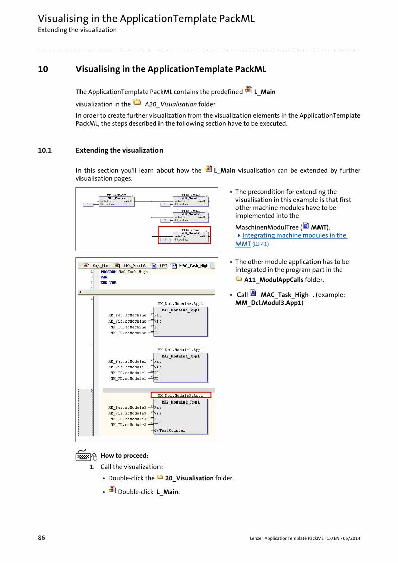
Visualising in the ApplicationTemplate PackMLExtending the visualization
86 Lenze · ApplicationTemplate PackML · 1.0 EN - 05/2014
_ _ _ _ _ _ _ _ _ _ _ _ _ _ _ _ _ _ _ _ _ _ _ _ _ _ _ _ _ _ _ _ _ _ _ _ _ _ _ _ _ _ _ _ _ _ _ _ _ _ _ _ _ _ _ _ _ _ _ _ _ _ _ _
10 Visualising in the ApplicationTemplate PackML
The ApplicationTemplate PackML contains the predefined L_Main
visualization in the A20_Visualisation folder
In order to create further visualization from the visualization elements in the ApplicationTemplatePackML, the steps described in the following section have to be executed.
10.1 Extending the visualization
In this section you'll learn about how the L_Main visualisation can be extended by furthervisualisation pages.
How to proceed:
1. Call the visualization:
• Double-click the 20_Visualisation folder.
• Double-click L_Main.
• The precondition for extending the visualisation in this example is that first other machine modules have to be implemented into the
MaschinenModulTree ( MMT). Integrating machine modules in the MMT ( 41)
• The other module application has to be integrated in the program part in the
A11_ModulAppCalls folder.
• Call MAC_Task_High . (example: MM_Dcl.Modul3.App1)
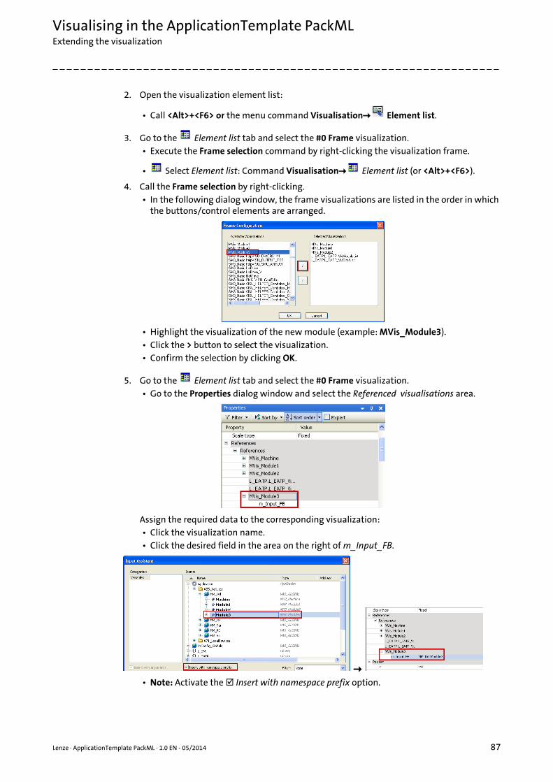
Lenze · ApplicationTemplate PackML · 1.0 EN - 05/2014 87
Visualising in the ApplicationTemplate PackMLExtending the visualization
_ _ _ _ _ _ _ _ _ _ _ _ _ _ _ _ _ _ _ _ _ _ _ _ _ _ _ _ _ _ _ _ _ _ _ _ _ _ _ _ _ _ _ _ _ _ _ _ _ _ _ _ _ _ _ _ _ _ _ _ _ _ _ _
2. Open the visualization element list:
• Call <Alt>+<F6> or the menu command Visualisation Element list.
3. Go to the Element list tab and select the #0 Frame visualization.• Execute the Frame selection command by right-clicking the visualization frame.
• Select Element list: Command Visualisation Element list (or <Alt>+<F6>).
4. Call the Frame selection by right-clicking.• In the following dialog window, the frame visualizations are listed in the order in which
the buttons/control elements are arranged.
• Highlight the visualization of the new module (example: MVis_Module3).• Click the > button to select the visualization.• Confirm the selection by clicking OK.
5. Go to the Element list tab and select the #0 Frame visualization.• Go to the Properties dialog window and select the Referenced visualisations area.
Assign the required data to the corresponding visualization:• Click the visualization name.• Click the desired field in the area on the right of m_Input_FB.
• Note: Activate the Insert with namespace prefix option.

Visualising in the ApplicationTemplate PackMLDefining the properties of buttons
88 Lenze · ApplicationTemplate PackML · 1.0 EN - 05/2014
_ _ _ _ _ _ _ _ _ _ _ _ _ _ _ _ _ _ _ _ _ _ _ _ _ _ _ _ _ _ _ _ _ _ _ _ _ _ _ _ _ _ _ _ _ _ _ _ _ _ _ _ _ _ _ _ _ _ _ _ _ _ _ _
Use the Input assistance from the Application element• ...select the desired function block that provides the data for the corresponding
visualization page.
10.2 Defining the properties of buttons
How to proceed:
1. Extend Vis_eFrame in the A71_LocalSources\Structs ENUM folder:
Add the name of the visualization manually, example: MVis_Module3
Note: The arrangement of entries in the ENUM Vis_eFrame has to correspond to the
selected order of #0 Frame of the L_Main visualization.
2. Go to A20_Visualisation\SubVisu folder and select the Keys_Main visualization.
3. Create a new button.• Highlight the Module 2 button:
• Right-click Copy
• Right-click Insert• Place the button on the desired position.• Rename button (example: Module 3):
4. Go to the Properties dialog of the Module 3 button and select the Color variables\Toggle color variable.
5. Adapt the value of the button copied before to the new name (example: Module3)

Lenze · ApplicationTemplate PackML · 1.0 EN - 05/2014 89
Visualising in the ApplicationTemplate PackMLAdding a visualization: Standard procedure
_ _ _ _ _ _ _ _ _ _ _ _ _ _ _ _ _ _ _ _ _ _ _ _ _ _ _ _ _ _ _ _ _ _ _ _ _ _ _ _ _ _ _ _ _ _ _ _ _ _ _ _ _ _ _ _ _ _ _ _ _ _ _ _
• Go to Toggle color and enter the line MVis.scVisuIntern.diFrame=Vis_eFrame.MVis_Module3.
6. Go to OnMouseUp and change the ST code to MVis.scVisuIntern.diFrame:=Vis_eFrame.MVis_Module3:
10.3 Adding a visualization: Standard procedure
• The visualization must be added in the
A20 Visualisation folder:
Right-click the A20 Visualisation folder and execute the following command:
Add object Visualization
• Allocate the desired name of the visualization.Click Open.
• The visualization has been added in the
A20 Visualisation folder.
• Create a Frame in the visualization: Create a frame from the Tools dialog box via drag&drop.

Visualising in the ApplicationTemplate PackMLAdding a visualization: Standard procedure
90 Lenze · ApplicationTemplate PackML · 1.0 EN - 05/2014
_ _ _ _ _ _ _ _ _ _ _ _ _ _ _ _ _ _ _ _ _ _ _ _ _ _ _ _ _ _ _ _ _ _ _ _ _ _ _ _ _ _ _ _ _ _ _ _ _ _ _ _ _ _ _ _ _ _ _ _ _ _ _ _
P
• Adapt the frame size.
• Execute the Frame selection command by right-clicking into the frame.• Accept the desired visualization to
the selection under Available visualisations by clicking the > button.
• Click OK to accept the visualization to the frame.
• Example : In order to accept the global error list, select the L_EATP.L_EATP_VisErrorList entry.
• Adapt/position the size of the visualization.
• For the error list (Error List), no further assignments are required.Result: The visualization is now serviceable
• Example: In order to insert a window for activating errors for a specific machine module, select the L_EATP.L_EATP_VisErrorSet visualization.
Example: Assigning the visualization for the ErrorsA block of the App1 module application of Module1.
• Assign the L_EATP.L_EATP_VisErrorSet visualization to the data source:• Assign the corresponding data
source in the Properties dialog window.
• Tip: The predefined visualization elements of the ApplicationTemplate PackML do not require any manual data assignments.• Therefore (after the compilation
process), logging in/ going online is possible without any extra effort involved.
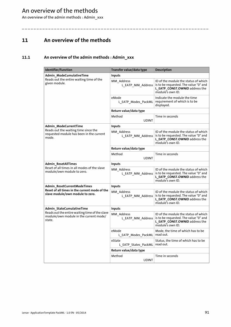
Lenze · ApplicationTemplate PackML · 1.0 EN - 05/2014 91
An overview of the methodsAn overview of the admin methods : Admin_xxx
_ _ _ _ _ _ _ _ _ _ _ _ _ _ _ _ _ _ _ _ _ _ _ _ _ _ _ _ _ _ _ _ _ _ _ _ _ _ _ _ _ _ _ _ _ _ _ _ _ _ _ _ _ _ _ _ _ _ _ _ _ _ _ _
11 An overview of the methods
11.1 An overview of the admin methods : Admin_xxx
Identifier/function Transfer value/data type Description
Admin_ModeCumulativeTimeReads out the entire waiting time of the given module.
Inputs
MM_AddressL_EATP_MM_Address
ID of the module the status of which is to be requested. The value "0" and L_EATP_CONST.OWNID address the module's own ID.
eModeL_EATP_Modes_PackML
Indicate the module the time requirement of which is to be displayed.
Return value/data type
MethodUDINT
Time in seconds
Admin_ModeCurrentTimeReads out the waiting time since the requested module has been in the current mode.
Inputs
MM_AddressL_EATP_MM_Address
ID of the module the status of which is to be requested. The value "0" and L_EATP_CONST.OWNID address the module's own ID.
Return value/data type
MethodUDINT
Time in seconds
Admin_ResetAllTimesReset of all times in all modes of the slave module/own module to zero.
Inputs
MM_AddressL_EATP_MM_Address
ID of the module the status of which is to be requested. The value "0" and L_EATP_CONST.OWNID address the module's own ID.
Admin_ResetCurrentModeTimesReset of all times in the current mode of the slave module/own module to zero.
Inputs
MM_AddressL_EATP_MM_Address
ID of the module the status of which is to be requested. The value "0" and L_EATP_CONST.OWNID address the module's own ID.
Admin_StateCumulativeTime Reads out the entire waiting time of the slave module/own module in the current mode/state.
Inputs
MM_AddressL_EATP_MM_Address
ID of the module the status of which is to be requested. The value "0" and L_EATP_CONST.OWNID address the module's own ID.
eModeL_EATP_Modes_PackML
Mode, the time of which has to be read out.
eStateL_EATP_States_PackML
Status, the time of which has to be read out.
Return value/data type
MethodUDINT
Time in seconds
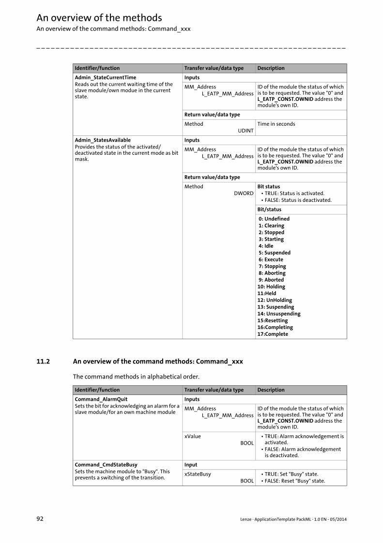
An overview of the methodsAn overview of the command methods: Command_xxx
92 Lenze · ApplicationTemplate PackML · 1.0 EN - 05/2014
_ _ _ _ _ _ _ _ _ _ _ _ _ _ _ _ _ _ _ _ _ _ _ _ _ _ _ _ _ _ _ _ _ _ _ _ _ _ _ _ _ _ _ _ _ _ _ _ _ _ _ _ _ _ _ _ _ _ _ _ _ _ _ _
11.2 An overview of the command methods: Command_xxx
The command methods in alphabetical order.
Admin_StateCurrentTimeReads out the current waiting time of the slave module/own modue in the current state.
Inputs
MM_AddressL_EATP_MM_Address
ID of the module the status of which is to be requested. The value "0" and L_EATP_CONST.OWNID address the module's own ID.
Return value/data type
MethodUDINT
Time in seconds
Admin_StatesAvailableProvides the status of the activated/deactivated state in the current mode as bit mask.
Inputs
MM_AddressL_EATP_MM_Address
ID of the module the status of which is to be requested. The value "0" and L_EATP_CONST.OWNID address the module's own ID.
Return value/data type
MethodDWORD
Bit status• TRUE: Status is activated.• FALSE: Status is deactivated.
Bit/status
0: Undefined 1: Clearing 2: Stopped 3: Starting 4: Idle 5: Suspended 6: Execute 7: Stopping 8: Aborting 9: Aborted10: Holding11:Held12: UnHolding13: Suspending14: Unsuspending15:Resetting16:Completing17:Complete
Identifier/function Transfer value/data type Description
Identifier/function Transfer value/data type Description
Command_AlarmQuitSets the bit for acknowledging an alarm for a slave module/for an own machine module
Inputs
MM_AddressL_EATP_MM_Address
ID of the module the status of which is to be requested. The value "0" and L_EATP_CONST.OWNID address the module's own ID.
xValueBOOL
• TRUE: Alarm acknowledgement is activated.
• FALSE: Alarm acknowledgement is deactivated.
Command_CmdStateBusySets the machine module to "Busy". This prevents a switching of the transition.
Input
xStateBusyBOOL
• TRUE: Set "Busy" state.• FALSE: Reset "Busy" state.
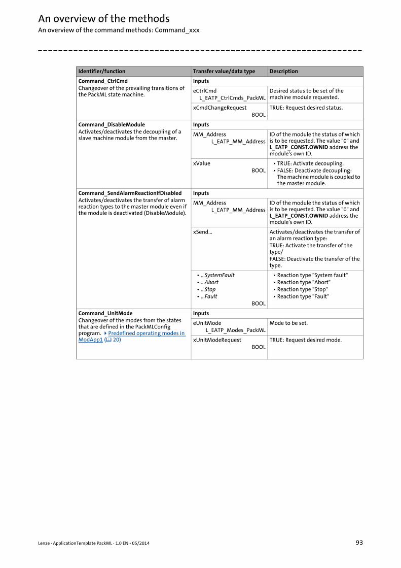
Lenze · ApplicationTemplate PackML · 1.0 EN - 05/2014 93
An overview of the methodsAn overview of the command methods: Command_xxx
_ _ _ _ _ _ _ _ _ _ _ _ _ _ _ _ _ _ _ _ _ _ _ _ _ _ _ _ _ _ _ _ _ _ _ _ _ _ _ _ _ _ _ _ _ _ _ _ _ _ _ _ _ _ _ _ _ _ _ _ _ _ _ _
Command_CtrlCmdChangeover of the prevailing transitions of the PackML state machine.
Inputs
eCtrlCmdL_EATP_CtrlCmds_PackML
Desired status to be set of the machine module requested.
xCmdChangeRequestBOOL
TRUE: Request desired status.
Command_DisableModuleActivates/deactivates the decoupling of a slave machine module from the master.
Inputs
MM_AddressL_EATP_MM_Address
ID of the module the status of which is to be requested. The value "0" and L_EATP_CONST.OWNID address the module's own ID.
xValueBOOL
• TRUE: Activate decoupling.• FALSE: Deactivate decoupling:
The machine module is coupled to the master module.
Command_SendAlarmReactionIfDisabledActivates/deactivates the transfer of alarm reaction types to the master module even if the module is deactivated (DisableModule).
Inputs
MM_AddressL_EATP_MM_Address
ID of the module the status of which is to be requested. The value "0" and L_EATP_CONST.OWNID address the module's own ID.
xSend... Activates/deactivates the transfer of an alarm reaction type:TRUE: Activate the transfer of the type/ FALSE: Deactivate the transfer of the type.
• ...SystemFault• ...Abort• ...Stop• ...Fault
BOOL
• Reaction type "System fault"• Reaction type "Abort"• Reaction type "Stop"• Reaction type "Fault"
Command_UnitModeChangeover of the modes from the states that are defined in the PackMLConfig program. Predefined operating modes in ModApp1 ( 20)
Inputs
eUnitModeL_EATP_Modes_PackML
Mode to be set.
xUnitModeRequestBOOL
TRUE: Request desired mode.
Identifier/function Transfer value/data type Description

An overview of the methodsAn overview of the status methods: Status_xxx
94 Lenze · ApplicationTemplate PackML · 1.0 EN - 05/2014
_ _ _ _ _ _ _ _ _ _ _ _ _ _ _ _ _ _ _ _ _ _ _ _ _ _ _ _ _ _ _ _ _ _ _ _ _ _ _ _ _ _ _ _ _ _ _ _ _ _ _ _ _ _ _ _ _ _ _ _ _ _ _ _
11.3 An overview of the status methods: Status_xxx
Identifier/function Transfer value/data type Description
Status_DisabledModuleChecks if the slave module/the own module has been decoupled ("disabled") from the master.
Inputs
MM_AddressL_EATP_MM_Address
ID of the module the status of which is to be requested. The value "0" and L_EATP_CONST.OWNID address the module's own ID.
xValueBOOL
• TRUE: Decoupling is activated.• FALSE: Decoupling is deactivated/
The machine module is coupled to the master module.
Return value/data type
MethodBOOL
• TRUE: Machine module is decoupled (status: "disabled").
• FALSE: Machine module is coupled to the master (status: "enabled").
Request master module
Status_MasterUnitModeCurrentReturns the current mode of the master module.
Return value/data type
MethodL_EATP_Modes_PackML
-
Status_MasterUnitStateCurrentReturns the current status of the master module.
Return value/data type
MethodL_EATP_States_PackML
-
Request states
Status_StateBusyChecks if the modules are in "Busy" status. If so, the changeover of the state machine is prevented.
Inputs
xAllOrSlavesBOOL
• TRUE: Request all modules.• FALSE: Only request the slave
modules.
Return value/data type
MethodBOOL
• TRUE: One of the modules is in the "Busy" status.
• FALSE: No module has the "Busy" status.
Status_StateChangeInProcess Checks if the requested module has currently carried out a state change.
Inputs
MM_AddressL_EATP_MM_Address
ID of the module the state of which is to be requested. The value "0" and L_EATP_CONST.OWNID address the module's own ID.
Return value/data type
MethodBOOL
• TRUE: State change is active.• FALSE: No state change.
Status_StateRequestedChecks if a state has been required in the requested module.
Inputs
MM_AddressL_EATP_MM_Address
ID of the module the state of which is to be requested. The value "0" and L_EATP_CONST.OWNID address the module's own ID.
Return value/data type
MethodBOOL
• TRUE: Status request is active.• FALSE: Currently no status request
at the module.
eStateRequestedL_EATP_States_PackML
Requested state of the module.
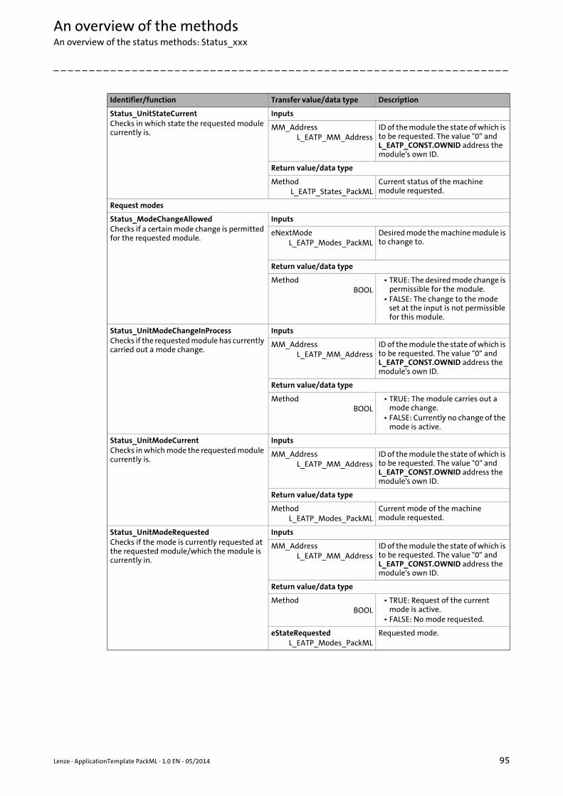
Lenze · ApplicationTemplate PackML · 1.0 EN - 05/2014 95
An overview of the methodsAn overview of the status methods: Status_xxx
_ _ _ _ _ _ _ _ _ _ _ _ _ _ _ _ _ _ _ _ _ _ _ _ _ _ _ _ _ _ _ _ _ _ _ _ _ _ _ _ _ _ _ _ _ _ _ _ _ _ _ _ _ _ _ _ _ _ _ _ _ _ _ _
Status_UnitStateCurrentChecks in which state the requested module currently is.
Inputs
MM_AddressL_EATP_MM_Address
ID of the module the state of which is to be requested. The value "0" and L_EATP_CONST.OWNID address the module's own ID.
Return value/data type
MethodL_EATP_States_PackML
Current status of the machine module requested.
Request modes
Status_ModeChangeAllowedChecks if a certain mode change is permitted for the requested module.
Inputs
eNextModeL_EATP_Modes_PackML
Desired mode the machine module is to change to.
Return value/data type
MethodBOOL
• TRUE: The desired mode change is permissible for the module.
• FALSE: The change to the mode set at the input is not permissible for this module.
Status_UnitModeChangeInProcessChecks if the requested module has currently carried out a mode change.
Inputs
MM_AddressL_EATP_MM_Address
ID of the module the state of which is to be requested. The value "0" and L_EATP_CONST.OWNID address the module's own ID.
Return value/data type
MethodBOOL
• TRUE: The module carries out a mode change.
• FALSE: Currently no change of the mode is active.
Status_UnitModeCurrentChecks in which mode the requested module currently is.
Inputs
MM_AddressL_EATP_MM_Address
ID of the module the state of which is to be requested. The value "0" and L_EATP_CONST.OWNID address the module's own ID.
Return value/data type
MethodL_EATP_Modes_PackML
Current mode of the machine module requested.
Status_UnitModeRequestedChecks if the mode is currently requested at the requested module/which the module is currently in.
Inputs
MM_AddressL_EATP_MM_Address
ID of the module the state of which is to be requested. The value "0" and L_EATP_CONST.OWNID address the module's own ID.
Return value/data type
MethodBOOL
• TRUE: Request of the current mode is active.
• FALSE: No mode requested.
eStateRequestedL_EATP_Modes_PackML
Requested mode.
Identifier/function Transfer value/data type Description

Index
96 Lenze · ApplicationTemplate PackML · 1.0 EN - 05/2014
_ _ _ _ _ _ _ _ _ _ _ _ _ _ _ _ _ _ _ _ _ _ _ _ _ _ _ _ _ _ _ _ _ _ _ _ _ _ _ _ _ _ _ _ _ _ _ _ _ _ _ _ _ _ _ _ _ _ _ _ _ _ _ _
AA75 UserTags 58
Accessing structure variables of machine modules 57
Accessing structures of other machine modules 59
Accessing the module's intrinsic structure variables 57
ACD structure 59, 63
Acknowledging alarms 76
Acknowledging errors - response in the machine module 76
Adding further devices - EtherCAT bus system 37
Addressing the machine modules 17
Alarm information 80
appChannelLock 84
appChannelUnlock 84
Application notes (representation) 8
AT_ACTION_ADD_MODULE 41
AT_ACTION_ADD_MODULEAPPLICATION 54
AT_ACTION_CREATE_NEW_MODULE 40
AT_ACTION_CREATE_NEW_MODULEAPPLICATION 52
BBaseChannel 18
CChanging over transitions, methods 65
Command methods 92
Command_AlarmQuit 92
Command_CmdStateBusy 91
Communication between the machine modules 18
Compiling the project data 33
Consistent data transfer 83
Conventions used 7
Creating a machine module 40
Creating a project - standard procedure 25
Creating an additional operating mode 21
Creating module applications 52
DDefining alarms - standard procedure 76
Document history 6
Downloading and starting the PLC program 33
EElements of the ApplicationTemplate 15
E-mail to Lenze 98
Error handling 24, 75, 79Defining errors 75Triggering errors 78
Error ListExport CSV file 80
Error response types 75
Establishing communication with the controller 11
Extending the visualization 86
FFeedback to Lenze 98
GGetting started - operating the ApplicationTemplate 34
IInfluencing state transitions 71
Inserting an axis 48
Integrating a created machine module 41
Integrating a module application 54
Integrating I/O modules 50
LLogbook 81
Logging in 33
MMAC_Task_Free 82
MAC_Task_High 82
MAC_Task_Mid 82
Machine module 16
Machine module (MM) 16
Machine module tree 15, 16
MachineModuleTree 15
MAP 17
Method overview - ApplicationTemplate 91
MM 16
MM_Dcl 30
MM_EmptyModule_PackML 40
MM_IO 30
MM_Par 30
MM_PD 30
MM_Vis 30
MMD structure 63
MMT 15
Modes 18
Modularising the automation system 27
Module address, absolute 17
Module address, relative 17
Module application 17
Module diagnostics 82
Module ID 46
ModuleAppCalls 17, 28, 30, 82
Multitasking 82
NNotes used 8
PProgramming with the module application 53
Index

Lenze · ApplicationTemplate PackML · 1.0 EN - 05/2014 97
Index
_ _ _ _ _ _ _ _ _ _ _ _ _ _ _ _ _ _ _ _ _ _ _ _ _ _ _ _ _ _ _ _ _ _ _ _ _ _ _ _ _ _ _ _ _ _ _ _ _ _ _ _ _ _ _ _ _ _ _ _ _ _ _ _
QQuery example
Querying the state machine (IF condition) 73Querying the TARGET status of the state machine of the higher-level master 73
Query examplesState machine 72
RRenaming a module 41
Renewed coupling of machine modules 71
SSafety 10
Safety instructions (representation) 8
Screenshots 5
Standard response 70
Starting the ApplicationTemplate 31
State entry 74
State exit 74
State machine 23, 64
State machine - program examples 72
State transitions and conditions - overview 23
State transitions in detail 67
States 68
Status methods 94
Structure of a machine module 16
Structuring within a machine module 28
TTarget group 5
Target of the ApplicationTemplate 13
Transferring the functionality of the machine structure to machine modules 27
Transferring the project to the control system (logging in) 33
UUserTags 58
VValidity of the documentation 6
VisualisationDefining buttons 88
Visualisation of the machine modules 35
WWorking with the ApplicationTemplate 36
98 L
Your opinion is important to us
These instructions were created to the best of our knowledgeand belief to give you the best possible support for handlingour product.
If you have suggestions for improvement, please e-mail us to:
Thank you for your support.
Your Lenze documentation team

© 05/2014
Lenze Automation GmbHHans-Lenze-Str. 1D-31855 AerzenGermany
Service Lenze Service GmbHBreslauer Straße 3D-32699 ExtertalGermany
+49 (0)5154 – 82 -0 00 80 00/24 4 68 77 (24 h helpline)
+49 (0)5154 – 82 - 2800 +49 (0)51 54/82-11 12
[email protected] [email protected]
www.Lenze.com
SHPPLCDSD-NG 13464162 EN 1.0 TD11
10 9 8 7 6 5 4 3 2 1