plb0h4545xo series 800ma magic blue led die - … series 800ma magic blue led die ... amb = +25oc,...
TRANSCRIPT

PLB0H4545xO Series 800mA Magic Blue LED Die Advanced Product Information
Description Plessey MAGIC PLB0H4545xO blue LED die are designed for a wide range of high power, 24V
applications such as spot lights, high bay lighting and track lighting. The light is emitted from the top
surface only and is close to a Lambertian distribution. The die is suitable for assembling as a single
device, or in strings or arrays for specific applications. The LEDs are supplied on a blue tape in single
radiant flux and wavelength bins, to provide close uniformity.
Features
Blue LED die
24V operating voltage
Single surface top-emitting
Wide wavelength range
GaN-on-Si die technology
Applications
Spot lighting
Architectural lighting
High bay lighting
Track lighting
General lighting
Variant Colour Wavelength (nm)
Min. Max.
PLB0H4545MO Blue, phosphor 450 460
PLB0H4545PO Blue, visible 460 470
PLB0H4545TO Blue, visible 470 480
Page 2 of 7 Document number 294322 V2
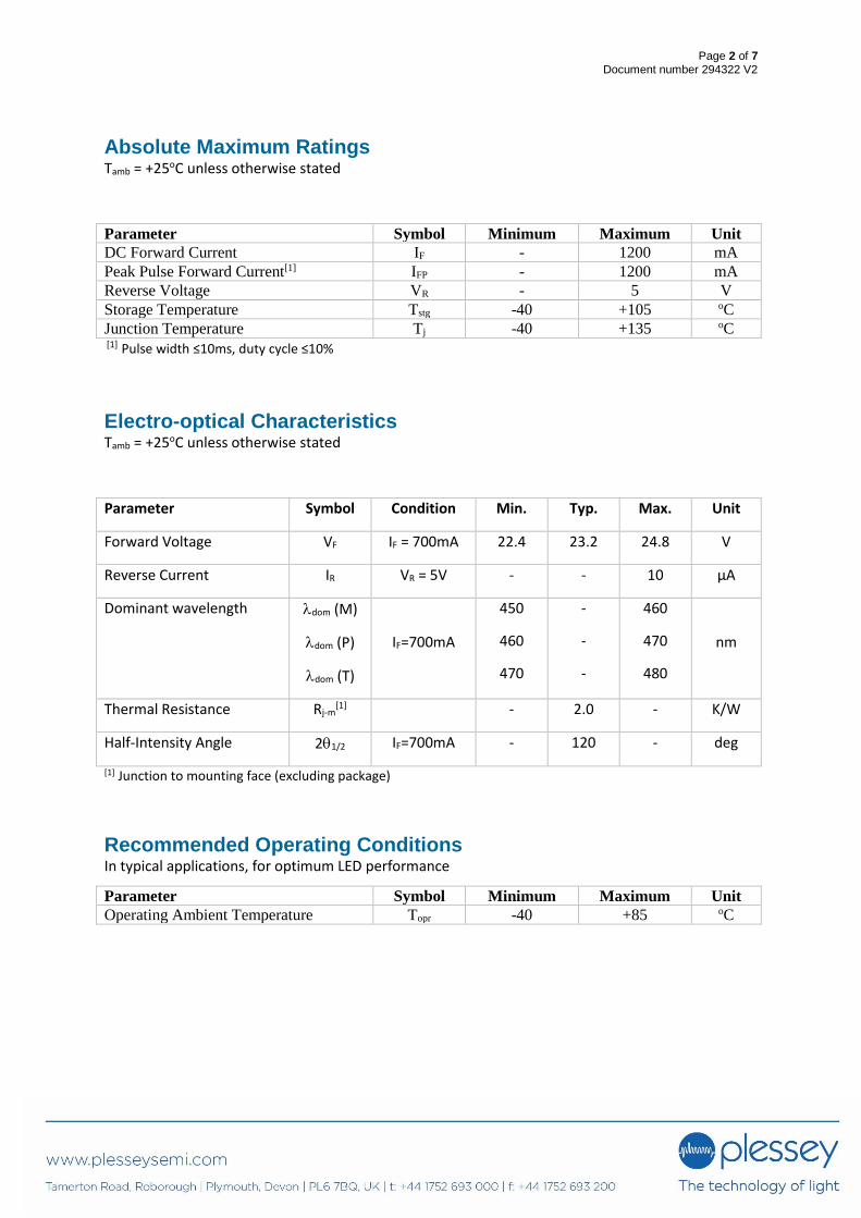
Absolute Maximum Ratings Tamb = +25oC unless otherwise stated
Parameter Symbol Minimum Maximum Unit
DC Forward Current IF - 1200 mA
Peak Pulse Forward Current[1] IFP - 1200 mA
Reverse Voltage VR - 5 V
Storage Temperature Tstg -40 +105 oC
Junction Temperature Tj -40 +135 oC [1] Pulse width ≤10ms, duty cycle ≤10%
Electro-optical Characteristics Tamb = +25oC unless otherwise stated
Parameter Symbol Condition Min. Typ. Max. Unit
Forward Voltage VF IF = 700mA 22.4 23.2 24.8 V
Reverse Current IR VR = 5V - - 10 µA
Dominant wavelength dom (M)
dom (P)
dom (T)
IF=700mA
450
460
470
-
-
-
460
470
480
nm
Thermal Resistance Rj-m[1] - 2.0 - K/W
Half-Intensity Angle 21/2 IF=700mA - 120 - deg
[1] Junction to mounting face (excluding package)
Recommended Operating Conditions In typical applications, for optimum LED performance
Parameter Symbol Minimum Maximum Unit
Operating Ambient Temperature Topr -40 +85 oC

Page 3 of 7 Document number 294322 V2
Radiant Flux Groups IF = 700mA, Tamb = +25oC, unless otherwise stated
Variant Group
Radiant Power (mW)
Min. Max.
PLB0H4545MO
&
PLB0H4545PO
&
PLB0H4545TO
8M 5,800 6,210
9M 6,210 6,650
1N 6,650 7,120
2N 7,120 7,620
3N 7,620 8,160
4N 8,160 8,740
[1] Tolerance ±11% and measured in air
Dominant Wavelength Groups IF = 700mA, Tamb = +25oC, unless otherwise stated
Group λd [1](nm) Group λd [1](nm)
Min. Max. Min. Max.
M1 450 452.5 P3 465 467.5
M2 452.5 455 P4 467.5 470
M3 455 457.5 T1 470 472.5
M4 457.5 460 T2 472.5 475
P1 460 462.5 T3 475 477.5
P2 462.5 465 T4 477.5 480
[1] Tolerance ±1nm
Forward Voltage Bin Groups
IF = 700mA, Tamb = +25oC, unless otherwise stated
Group VF [1] (V)
Min. Max. V1 22.4 23.2
V2 23.2 24.0
V3 24.0 24.8 [1] Tolerance ±0.10V

Page 4 of 7 Document number 294322 V2
Mechanical Specifications
Parameter Dimensions (µm) Tolerance (µm)
Die size 4500 x 4500 ±10
Die thickness 150 ±10
Al bond pad size 100 x 100 ±10
Al bond pad thickness 2 ±0.2
Ag back metal thickness 0.4 ±0.05
Top view Side view
(Actual colour of bond pad is aluminum-grey)
Anode pads
Cathode pads
All pads should be bonded out
Aluminium anode and
cathode pads
2um thick
Silver back metal
0.4um thick
Page 5 of 7 Document number 294322 V2
Handling Instructions Plessey LEDs are not designed to operate with reverse bias.
Precautions are required to prevent reverse bias in applications and during handling.
Page 6 of 7 Document number 294322 V2
Legal Notice
Product information provided by Plessey Semiconductors Limited (“Plessey”) in this document is believed to be
correct and accurate. Plessey reserves the right to change/correct the specifications and other data or
information relating to products without notice but Plessey accepts no liability for errors that may appear in
this document, howsoever occurring, or liability arising from the use or application of any information or data
provided herein. Neither the supply of such information, nor the purchase or use of products conveys any
licence or permission under patent, copyright, trademark or other intellectual property right of Plessey or third
parties.
Products sold by Plessey are subject to its standard Terms and Conditions of Sale that are available on request.
No warranty is given that products do not infringe the intellectual property rights of third parties, and
furthermore, the use of products in certain ways or in combination with Plessey, or non-Plessey furnished
equipments/components may infringe intellectual property rights of Plessey.
The purpose of this document is to provide information only and it may not be used, applied or reproduced (in
whole or in part) for any purpose nor be taken as a representation relating to the products in question. No
warranty or guarantee express or implied is made concerning the capability, performance or suitability of any
product, and information concerning possible applications or methods of use is provided for guidance only and
not as a recommendation. The user is solely responsible for determining the performance and suitability of the
product in any application and checking that any specification or data it seeks to rely on has not been
superseded.
Products are intended for normal commercial applications. For applications requiring unusual environmental
requirements, extended temperature range, or high reliability capability (e.g. military, or medical applications),
special processing/testing/conditions of sale may be available on application to Plessey.
Contact Customer Enquiries/Sales +44 1752 693000 | [email protected] www.plesseysemi.com Plessey Semiconductors Ltd | Plymouth Tamerton Road, Roborough Plymouth, Devon PL6 7BQ United Kingdom P: +44 1752 693000 F: +44 1752 693700

Page 7 of 7 Document number 294322 V2