platinum curve stairlift installation manualschodolez.info/pinum/installation pinum.pdf · giving...
TRANSCRIPT
1
Platinum Curve Stairlift
Installation Manual
THIS GUIDE IS COMPANY CONFIDENTIAL.
PLEASE RETAIN THIS GUIDE. THIS GUIDE IS NOT TO BE LEFT WITH THE CUSTOMER.
Exclusively Curved

2
Contents Page
Stairlift Discription ……………………………………………………………………… Controls ……………………………………………………………………………….………………………………………………………………..
Swivel Seat ……………………………………………………………….……………………………………………………………………..
Charging Points ………………………..…………………………………………………………………………………………………………….
Remote Controls ………………..…………………………………………………………………………………………………………………….
Kitting List …………………………………………....................................................................
Required Installation Equipment …………………………....................................................
Installing the Stairlift ………………………………………..................................................... Installation Drawing ………………………………………………………….........................................................................................
Assembling the Rail …………………………………………………....................................................................................................
Fixing the Rail Assembly in Place ………………………………………………………………………………………………………………..
Fitting the Carriage to the Rail ……………………………………………………………….. Fitting the Batterys …………………………………………………………………………………………………………........................
Fitting the Combined End Stops/Charging Ramps …………………………………………………………………………………………..
Charge Circuit ……………………………………………………………………………………………………………………………………...
Intemediate Charge Point …………………………………...........................................................................................................
Fitting the Chair to Carriage ………………………………………………………………………………………………………………..
Chair and Carriage Electrical Connections ……………………………………………………………………………………………………..
Chair ergonomic Alteration …………………………………………….…………………………………………………………………………….
Test Running Stairlift Unladen and Unprogrammed …………..….…………………………...
Programming The Carriage……….……………………………………………………………….. Installing Remote Controls ……………………………………………...........................................................................................................
Test Running the Stairlift Fully Laden and Programmed .……………………………………
Final Checks ……………………………………………….…………………………………… Contract/Installation drawing ……………………………………………….........................................................................................
Electrical, Battery and Operational Tests ……………………………………………………………………………………………………..
Certificate for Test and Examination After Installation …………………………………………………………………………………………..
Instructing the User ……………………………………………………………………………..
Paperwork …………………………………………………………………………………………... Test Certificate ……………………………………………………………………………………………………………………………………...
User Guide ……………………………………………………………………………………………………………………………………...
Offset Footrest Option ……………………………………………………………………………...
Connection Diagram ……………………………………………………………………………..
Technical Information …………………………………………………………………………….. Weight limits ……………………………………………………………………………………………………………………………………...
Operating Periods ………………………………………………………………………………………………………….......................................
Handwinding the Stairlift …………………………………………………………………………………………………………………………..
Diagnostic codes ……………………………………………………………………………………. Mains Power, Battery Power and Power Cuts ……………………………………………………………………………………………………..
Servicing …………………………………………………………………………………………..
4 5
6
7
7
8
9
11 11
12
14
15 16
18
19
20
21
22
23
25
25 28
31
32 32
32
32
34
35 35
35
36
37
38 38
38
38
39 41
42
3
About this Manual
Description of this manual
This manual is intended to show you how to install a Platinum Curve stairlift.
This manual contains detailed instructions about:
Intended Audience and their Required Knowledge
Typical Kitting List of Parts in a Platinum Curve stairlift
Required Installation Equipment you will need to install a stairlift
Health and Safety Guidance
Installing the Stairlift
Testing the Stairlift
Troubleshooting
Technical Information and System Status Codes
Instructing the User how to Use the Product
Paperwork
Quick Reference Guide
You should also have a User Guide to refer to – you must give this to the resident when the installation is completed.
Intended Audience
This manual has been written to be used by specialist trained stairlift installers.
The information in this guide assumes that you have already completed specialist training on how to install a Platinum Curve stairlift and you have perfomed an installation before, either at a customers dwelling or as part of a training course.
This manual is not intended as a training guide.
This manual is not intended to show an unskilled person how to install a stairlift.
Required Knowledge
This manual assumes that you have the following knowledge:
Basic Mechanical Skills - so you understand what the components of the stairlift do and how they fit and work together
Basic Wiring Skills - so you understand how the stairlift is connected to the mains power supply; and what the electrical components of the stairlift do and how they fit and work together
Health and Safety Awareness - so you are fully aware of and responsible for the health and safety of yourself and the people around you

4
About the Stairlift
No Meaning No Meaning
1 Arm rests (fold up and down) 9 Battery Isolator Switch
2 Lap Belt 10 Seat (folds up and down)
3 Seat Swivel Lever 11 Keyswitch
4 Powered footrest control (if option fitted) 12 Direction Control
5 Emergency Hand-wind Mechanism 13 Mains Power Switch
6 Diagnostic Display 14 Charging Point
7 Safety Limit Covers 15 Remote Control
8 Footrest (folds up and down)
These numbers are used this Installation Manual and the User Guide.
1
11
10
9
2
3
4
7
5
6
12
8

5
Controls
Mains Power Switch
The stairlift should be plugged in at the nearest mains socket. This could be at the top or bottom of the stairs.
The lift needs to be plugged in and switched on at all times. When the power is on, a green indicator light will be shown on the power supply, mounted nearby.
Battery Isolator Switch
The Battery Isolator Switch (9) is used to switch the stairlift on or off.
This should be left switched on at all times
Diagnostic Display
The diagnostic display (6) displays the current status. If any faults develop with the operation of the lift they will be displayed here. For a list of codes please see System Status Codes section in this manual.
Key Switch
The Key Switch (11) is used to lock the stairlift.
The Key Switch is located on the underside of the armrest which contains the direction control.
Direction Control
The Direction control (12) is red and located on the end of one of the armrests.
To move the chair, push and hold the joystick in the direction you want to move.
There is a short delay before the stairlift will start or change direction.
Footrest
The footrest (8) folds up and down manually.
Powered footrest option.
There is an option of an automatic powered footrest. If this option is fitted the powered footrest can be operated by using the powered footrest control (4). This is located on the underside of the opposite armrest containing the direction control

6
Swivel Seat
For safety, the seat (10) is locked into one of two positions. In the normal travel position, the seat will be locked into position with your back parallel to the track. This is so you do not catch your feet on the steps during travel. The lift will not travel unless the the seat is locked into this position.
The seat can be swivelled approx. 85 degrees to allow easy access when the lift is at the top of the stairs. To rotate the seat, lift one of the Seat Swivel Levers (3), and swivel towards the landing until the seat comes to a stop then release the lever to lock the seat in place. Make sure the seat is locked before you try to sit down or get up from it.
To return the seat to the normal travel position, lift one of the seat swivel levers (3) and swivel away from the landing until the seat comes to a stop then release the lever to lock the seat in place.
The seat only swivels at the top of the stairs.
If you try to swivel the seat whilst the lift is moving, the chair will stop.
Powered Swivel Option.
There is an option of an automatic powered swivel. If this option is fitted, when reaching the top of the stairs, keep the direction control pressed upwards. After a short pause, the carriage will swivel towards the landing. To return the carriage to the normal travel position, press the direction control downwards and the chair will swivel back into the normal travelling position before moving down the stairs.

7
Safety Interlocks
The footrest and the motor unit are fitted with Safety Interlocks (7). These are pressure pads which will stop the lift if they come into contact with any obstructions.
If the lift stops because it has encountered an obstruction, a fault code will be displayed on the diagnostic display. Wait two or three seconds, then reverse away from the blockage.
Lap Belt
The Lap Belt (2) holds you safely on the seat as you climb or decend the stairs. Like a car seat belt, this extends from the holder to clip into a socket. The lap belt must be used every time the stairlift is used. Do not undo the lap belt until the chair reaches the end of the track.
Charging Points
These are located at the top and bottom of the track. The lift MUST be parked on a charging point when not in use. The stairlift will sound an audible beep if it is not parked on a charging point.
Remote Controls
The Remote Controls (15) work in the same way as the arm controls. The standard lift is supplied with 2 remote controls. These remote controls have 3 buttons. Up, Down and, if an intermediate charge point is required, park.

8
Typical Kitting List
A typical installation will use the following numbers of these parts:
Leg bases (number specified on the Installation Drawing)
Track sections (number specified on the installation drawing)
45mm long spirol pins for legs (two per leg)
40mm spirol pins for track joints (2 per Joint)
6.3mm by 30mm screws (4 per leg, plus brown Rawlplugs if a concrete/marble/stone staircase)
M6 by 40mm rack jointing bolts and M6 nuts (1 set per joint)
2 x End Stop/Charging Assemblies
6 x M5 x 10 buttonhead cap screws
2 x Red spade crimp connectors
2 x Red ring crimp connectors
White 2-core 0.5 sq mm cable (track length + 4 metres)
2 x cable grommets
4 x Track End Bungs
Leg Top bungs (1 per leg)
1 x PSU and plug
2 x Remote Controls, labels and holsters (unless more requested)
Red Rawlplugs (3 per wall control, 2 per charger)
8 x 1 Pozidrive wood screws (3 per wall control, 2 per charger)
2 x 9v PP3 batteries
2 x 12v 8.5 aH chair batteries
8 x 100 x 2.5 natural tie wraps
2 x self-adhesive cable clips
Installation Drawing
Chair top (check controls are on correct side)
Carriage
Silicone or synthetic PTFE Lubricant for the racking
1 x Manual Winding Handle (to be left with the user)
1 x User Guide (to be left with the user)

9
Required Installation Equipment
To perform a typical installation you will need to use the following types of equipment:
Safety Goggles and Rigger Gloves
Spirit level, plus 5 metre tape measure
Drillbits:
6mm, 5.9mm, 5mm & 4.2mm HSS Drill Bits. 5mm Tap
8mm masonary drill bits (for drilling into brick, stone, concrete, etc)
No 3 Screwdriver bit and extension bar for drill to use on footplate screws
Combination Spanners / Sockets
One set of Combination Spanners, from M6 to M24 in size
Socket set, 2.5 mm to 20mm - ideally with ratchet drive
7mm Socket Wrench (with short /stubby arm for use in confined spaces)
Torque Wrench, 17mm socket & 4mm allen key bit
One set of metric Allen Keys
Screwdrivers:
One set of Crosshead screwdrivers (either Philips or PoziDrive),
Stubby Philips screwdriver
One set of flat bladed screwdrivers, in various sizes
Terminal screwdriver
Anti-static wrist strap
Electric drill (varispeed with hammer/non-hammer action) (either 240V mains-powered or 24V cordless)
Wire strippers
Dowel or metal rod to push cable through the track sections
Electrical or Combination pliers and Electrical side cutters
Heavy-duty extension lead
20oz claw or ball-pein hammer
5mm x150mm pin punch with pointed tip
Long-nose pliers
Angle-finder
Digital multi-meter/clamp meter (must be capable of measuring DC currents of up to 30A for at least 5 seconds)
Section of racking or rack clamp to use for clamping track sections together
Several sets of curved jaw vise-grips (with suitably padded jaws)

10
Health & Safety Guidance
Electrical Safety
Installation of the stairlift is mainly a manual process. Although you do need to plug the stairlift into a mains power supply socket, this socket MUST already have been installed by a qualified electrician.
All work on the 240Volt system must be done by a qualified electrician.
Safe Working Practices
When installing the stairlift, follow safe working practices in these areas:
Working at heights or on the stairs
Working with power tools or equipment which generate noise
Be aware of the risks of equipment falling from a height. For example, tools falling through open-treaded staircases or through banister rails, or equipment falling or sliding down stairs.
Giving Guidance to the Home Owner
Important – Intruder Alarms Intruder alarms often have sensor pads at the top or bottom of staircases or on one or more steps. There may also be alarm wires hidden under a carpet or tucked under a skirting board.Check whether any such sensors or cables need to be moved before drilling into a staircase or floor.
Provide guidance to the home owner about what safety risks they and any other people might be exposed to during the installation. For example
Movement of equipment and tools posing a risk to the buildings or things in it (such as pictures, paintings or ornaments)
Cables and other equipment posing a trip hazard - especially on or near stairs
Live electrical equipment (such as electric drills) posing a hazard (for example, if used inappropriately by children)
Potentially sharp equipment (such as saws, drills bits, knives or chisels)
Potential noise due to the use of power tools
Potential creation of airborne dust
Remember to let the resident know you will take them through how to use the stairlift, so they can let some-one else know what time a demonstration might take place.
Preparing the Workplace
Before you start the installation, make sure of a Safe Working Environment, with enough space to assemble the stairlift assembly and for you to work around it.
Make sure any loose or fragile property (such as pictures or ornaments) is located in a safe place away from the working area.
Insect the area for potentioal obstructions such as central heating pipes, hidden cables, underfloor heating,etc.

11
Installing the Stairlift
Understanding the Installation Drawing
The installation of a stairlift is specific to each site. Details of components and installation requirements are listed on the Installation Drawing and Kitting Checklist which are contained within the Kit box.This includes detailed measurements of how components should be arranged and precisely where and at what height they should be fitted. Example of an installation drawing is shown below:
No Description Information
1 Elevation Shows rail start and finish points and rail clearance over bottom and top noses.
2 3D Rendering Shows number of rail sections and which risers leg bases are on.
3 Options information Information on fitted options such as powered footrests etc.
4 Contract information Customer name, order reference, drawing number etc
5 Plan Drawing Shows rail to wall distances and which risers leg bases are on.
6 Leg Height Table Shows leg sizes and total leg height from step (approx.)
No. Leg Height off the Floor Foot Post
1 295.77 35 291
2 578.27 200 550
3 764.30 350 650
4 961.16 500 800
5 804.43 350 650
1
2
Total Length 2350mm Power Swivel Yes Power Footrest - Intermediate Charge Points - Extra Remote Controls -
3
4 5 6

12
Laying out the Components
Each complete stairlift consists of the carriage box, the chair box, the kit box and several rail sections. A Kitting List is included in the kit box detailing all of the parts you have received.
Remove any protective packaging from the components.
It is usually best to start at the bottom of the stairs, and work your way upstairs.
Layout the equipment in the order in which it will be installed, making sure you have all the necessary components. This will include major items, as well as fastenings (such as spirol pins, nuts/bolts) and tools (mole grips and clamps).
Tip. Paint can build up in the pre drilled and tapped holes in the racking on the top
and the bottom rail assembly sections. You will use these holes later on in the installation to connct the 0v side of the charge circuit. Clean these holes with a 5mm tap to ensure an easy fit when rail is set close to wall.
Assembling the rail
The leg bases provide stability to the stairlift and maintain it at the correct height about the ground. Place the correct leg bases onto the correct steps using the information contained in the table on the installation drawing.
Lower the rail support legs of the first (lowermost) rail assembly into the leg bases which will hold it in place. If there is the space it may be easier to place all rail assembly pieces into the relevant leg bases but do not join yet.
If possible, thread the charge current cable through the bottom rail tube of each section now. If not possible you will have to thread the dc cable through each section as you go along. If intermediate charge points are required holes will be drilled into the underside of the bottom rail to enable the charge current cable to exit and enter the rail at these points.
Clamp the rail support legs of the first rail assembly at the correct height on the leg bases (as needed) using vice grips with suitable padding. The legs should be clamped to ensure that the rail stands level vertically. The leg height shown on the Installation Drawing is only an approximate guideline.

13
Set the height of the next rail section approximately with vice grips. Slide the higher rail assembly downwards into the lower rail assembly taking care not to trap charge current cable. Again, clamp the legs to ensure that the rail stands level vertically. Check first section for level
Use a set of clamps with a rack alignment block to set the pitch of the rack joint. This to ensure that the carriage has a smooth transition from one section to another whilst running.
Once held in place with the clamp, fit and tighten the M6 x 40mm bolts with M6 nuts..
Taking care not to trap the DC cable, hammer the 40mm spirol pins through the pre drilled holes in the rail joints. Ensure there are two spirol pins on each joint on each rail. Ensure that each pin is flush with front of rail. Ensure that any swarf is removed from back of rail.
Tip. Paint can build up in the pre drilled holes. Use a 5.9mm dril to ensure that the
holes are clear before hammering the pins through. Also, use a 5mm pin punch with a pointed tip when hammering the pins through the rail. This will enable you to control direction of the pin accurately and will ensure you do not mark paint on track when hammering flush. If you look through the holes in the bottom rail tube you can see if the dc charge cable is obstructing. As the spirol pins are hollow, you can look through as they are hammered into place to ensure they do not cause an obstruction.
Repeat above steps until all the rail assembly pieces are together and the whole track is level.
Thread the dc power cable through the hole near the end of the track in both top and bottom sections of rail and secure using the screw-in cable grommets supplied.

14
Moving the Rail into the correct Position
The Rail Assemblies are now assembled, but still need to be aligned accurately on the stairs. Refer to the Installation Drawing for details of the distances that the rail should be set over the first and last noses (steps) and the clearances that should be set between the rail and any walls, newell posts or other obstructions.
Fastening the Rail Assembly in place
The Rail Assemblies now need to be fastened in place using the supplied 6.3 x 30mm wood screws. 4 per base.
Tip. If the rail is being fixed to bare wood, concrete, stone or marble, it is recommended
that the carriage and chair are loaded at this point to check all clearences. The easiest way to do this is to drill and fit one fixing pin in each leg that is clamped with the vice grips as described later in this section. Once these legs are pinned the vice clamps can be removed and the carriage loaded as described in the next section. Do not ride the lift at this point.
When the lift is in the correct position, ensure that the rail assemblies are correctly fastened in place as described below before testing lift under load.
Starting with the second leg, make sure the leg base is resting flat on the step/landing. If the step is not level it may be necessary to pack the leg base to ensure it stays level as it is screwed down.
Insert the first screw and tighten. The next screw inserted should be diagonally opposite. Insert the remaining screws.Use a spirit level to check that the legs remain vertical as they compress any carpet/underlay.
Using a 5.9mm HSS bit, drill through the pilot hole in the leg base and continue all the way through, taking care not to drill into anything behind the leg, or mark the base with the drill chuck.
Hammer the 45mm spirol pins through the drilled holes in the rail joint. Make sure there are two spirol pins on baseplate. Again, use a 5mm pin punch with a pointed tip when hammering the pins through the leg. This will enable you to control direction of the pin accurately and will ensure you do not mark paint on track when hammering flush.
Repeat this process for each leg, with two pins on each leg. Ensure that each pin is flush with front of baseplate. Ensure that any swarf is removed from back of baseplate.
If any wall brackets are specified on the drawing these can be fitted now or after the carriage has been loaded.
If specified, the wall brackets must be fitted before the stairlift is handed over to the user.
The rail is now ready for the carriage to be loaded.

15
Fitting the Carriage to the Rails
CAUTION: The weight of the Carriage is 34 kg when the batteries and all the components are installed.
Open the carriage box and remove the skate retention packing cardboard. Ensure that the top skate loom is free and will not catch the top skate assembly as it moves while travelling on the track. Pay close attention to the area where the top skate assembly comes into contact with the physical limits on the casting.
Tip. After opening the box, make sure that the cardboard that forms the handles is
pushed back through the sides of the box. The carriage can then be lifted easily out using the integral box tray.
The carriage can then be loaded on to the rail in one of 2 ways:
1. Insert the loading bar through the top skate rollers, ensuring that the male joint is pointing in the right direction.
Lift the carriage, using one hand on either side of the skate assembly to stop the carriage moving on the loading bar. Alternatively, suitable clamps or tie-wraps can be used to secure the carriage.
Slot the male joint into the top rail tube, letting the carriage hang vertically, and, removing any clamps/tie-wraps used, slide the carriage down the loading bar and engage the pinion and main load roller on the bottom skate assembly correctly.
2. Slot the male joint of the loading bar into the top rail tube.
Lift the carriage and thread the top skate rollers onto the loading bar. Holding the carriage vertical, slide it down the loading bar and engage the pinion and main load roller on the bottom skate assembly correctly.

16
A second, shorter, loading bar can be used in the bottom rail tube if you find it easier to fit this way. Lift the carriage and thread the top skate rollers onto the top loading bar. Holding the carriage vertical, slide it down the loading bar.
Ensure the main load roller is correctly positon and locate the bottom skate onto the shorter, bottom rail loading bar. As the carriage comes to rest the pinion should be correctly aligned for loading.
Before the carriage can be moved down the rail the two 12v, 8.5aH batteries must be fitted. The electromagnetic brake on the motor will not release until the batteries have been fitted. Do not try and force the carriage onto the rail without fitting the batteries as this could damage the brake.
Fitting the Batteries
CAUTION: When new, the 12V 35W 8.5Ah batteries will be pre-charged. These carry electrical charge, which provides a risk of electrical shock or fire if the battery terminals are shorted out. Although they are sealed batteries, they do contain battery acid, so damaged or leaking batteries pose a risk of burns.
Fold down the footrest and ensure the battery isolator switch (10) is turned off.
Remove the two 7mm nuts and plastic washers located at the bottom of each carriage side cover. These covers can then be removed taking care not to damage the locating lugs at the top. Disconnect the infra-red receiver cable from each side cover.
Remove the four pozi-drive screws found on the front of the carriage and allow the plastic carriage front cover to lean forward. This cover can be removed completely, if necessary, by un-plugging the 3 way cable to the Diagnostic Display PCB. If the powered swivel option is fitted there will also be another 3 way cable fitted. These cables can be replaced in either position.
In the battery compartment you will find the fused link, the rubber battery retention strap, a flat rubber divider and a stepped rubber divider.

17
Place the stepped rubber divider on the bottom of the battery compartment.
Place the first battery vertically in the compartment with the terminals at the top, facing towards you.
Place the flat rubber divider on to of the battery and then place the second battery on top of the first vertically in the compartment with the terminals at the bottom, facing towards you.
Connect the black lead to the –ve (black) terminal of the top battery and connect the red lead to the +ve (red) terminal of the bottom battery. Connect the fused link between the remaining –ve (black) and +ve (red) terminals as shown in the picture.
Once the batteries are fitted and connected the plastic front, and battery side carriage cover can be replaced.
Leave the PCB side cover off until later in the installation process.
As the batteries will enable the correct operation of the electro magnetic brake, the carriage can be hand-wound completely onto the track using the instructions printed on the plastic cover adjacent to the Hand Winding Socket (5).

18
Fitting the Combined End Stops/Charging Ramps
The combined end stops/charging ramp units are used, as the name suggests, to stop the carriage at the end of the rails and to recharge the batteries while the lift is not being used. They should be fitted at both the bottom and the top of the rail. The carriage batteries are charged when the brass plunger on the back of the bottom skate of the carriage comes into contact with the charge ramp.
The units can be used to set how high or low the start and finish point of the carriage will be on the completed stairlift.
Each unit consists of three methods of stopping the carriage. The usual method of stopping the carriage being the spring loaded plunger mounted on the end stop. This plunger connects with the sprung metal end stop plate on the bottom skate of the carriage. If this method fails for any reason, the shape of the charge ramp is such that if the carriage travels past it’s usual stopping point, the brass plunger on the carriage will be depressed too far and “over-run”. This will break the final limit circuit, bringing the carriage to a halt. In the unlikely event of both of the above methods failing, there is a physical buffer that covers the teeth on the racking, forcing the carriage to stop when the pinion comes into contact with it.
CAUTION:
The fixing of the end stop and the distance between the stop and the charge ramp is crucial to the safe and reliable operation of the stairlift.
To fit the combined end stops/charging unit, place the carriage in the correct position to allow the customer to easy access. Place the end stop unit on the bottom rail with the spring loaded plunger touching the metal end stop plate on the carriage and, holding the end stop unit in position move the carriage away along the track.
Drill and tap two holes in the lower rail using a 4.2mm drill bit and 5mm tap. Attach end stop with the M5 x 10 button head cap screws supplied.
When the carriage comes to rest against the end stop, the charge plunger on the carriage should make a good contact with the charge ramp on the endstop unit.
The plunger should travel between a third and half way up the first face of the charge ramp. Too little and a good electrical contact will not be made and the batteries will not charge reliably. Too far and the final limit circuit will be broken and the lift will not move.
This contact position can be set by moving the postion of the charge ramp along its mounting on the end stop assembly. When adjusting, ensure the charge current is not connected.

19
Connecting the Charge Circuit
A DC charger is used to supply power for the charging circuit. This power supply should be mounted using the bracket supplied near a convenient mains outlet socket. All cables must be securely clipped or trunked to the vicinity of either the top or bottom of the stairlift rail, in accordance with current regulations.
The DC output from the charger consists of 2 cores, plain black indicates 0v, black with a white dash indicates +v.
Take the 2 core cable that you installed in through the bottom rail of the track earlier. Strip back the outer insulator and approx 10mm of the inner blue insulator.
Join the blue core and the plain black 0v charger core together with the red crimp on eyelet connector supplied and fix this to the racking using the supplied M5 x 10 buttonhead cap screw.
Join the brown core and the +v black with whie dash charger core together with the supplied red crimp on spade connector and attach to the lug on the back of the charge ramp.
At the other end of the rail, take the 2 core cable that you installed in through the bottom rail of the track earlier. Strip back the outer insulator and attach the inner blue core to the rack using the red crimp on eyelet connector supplied and fix this to the racking using the supplied M5 x 10 buttonhead cap screws.
Attach the brown core to the lug on the back of the charge ramp with the supplied red crimp on spade connector.
Clip all wires neatly to the end stop assembly using the supplied tie wraps to ensure that they do not foul the carriage as it is moving.
Plug in and turn on the Power supply and test that each charge ramp is supplying approx 24v.
Intermediate Charge point
An intermediate charge point is available as an option. It can be used in 2 different ways.
1. As an auxillery charge point so that the carriage can be stored away from the bottom of the track if this causes an obstruction. The carriage will travel upwards to the next available charge point when the red park button is pressed on the remote control.

20
2. As a safe position for the customer to get on or off the lift on intervening floors. In addition to using the red park button on the remote control, by selecting the correct option from the menu system, the lift will also stop at the parking point from the joystick control, enabling the customer to either get off the lift, or, by pressing the control again continue to the next charging point.
If an intermediate charge point is required, this should be clamped to the racking in the correct position. The 2 core cable that you installed earlier will need terminating.
Strip back the insulator from both cables, connect both brown cores together using one of the crimp on spade connectors supplied.
At the other end of the rail, take the 2 core cable that you installed in through the bottom rail of the track earlier. Strip back the outer insulator and attach the inner blue core to the rack using the red crimp on eyelet connector supplied and fix this to the racking using the supplied M5 x 10 buttonhead cap screws.
Connect this to the lug on the back of the charge ramp.
Connect both blue cores together using one of the crimp on eyelet connectors supplied and attach to the racking using one of the M5 x 10 buttonhead cap screws supplied.
The charge point can be adusted to enable the charge pin on the carriage to make a good contact but not activate the final limit switch when passing.
Clip all wires neatly to the end stop assembly using the supplied tie wraps to ensure that they do not foul the carriage as it is moving.
Plug in and turn on the Power supply and test that each charge ramp is supplying approx. +27 VDC.

21
Fitting the Chair to the Carriage
Remove the chair from the packaging. The key for the keyswitch (11) is attached to one of the chair arms. Remove, insert into keyswitch and turn clockwise thru 90°.
In the packaging there will also be a plastic cover and 4 plastic pop rivets. Place these to one side for use later.
Remove the four 5mm allen key bolts, pictured right, from the carriage chassis. Leave the circular spacing plate in place. The spacing plate must be in place as the chair will catch on the top skate when swivelled otherwise.
Ensure that the holes in the spacing plate line up with the holes in the chassis underneath.
Place the chair onto the chassis in the correct position, ensuring the looms are passed through the centre of the swivel mechanism and not trapped.
Attach the chair to the carriage using the 4 x 5mm allen key bolts. Tighten to a torque of 20 Nm.
Swivel the chair, making sure it locks securely at either end of its travel and the swivel interlock switch activates and releases correctly.
22
Chair and carriage electrical connections
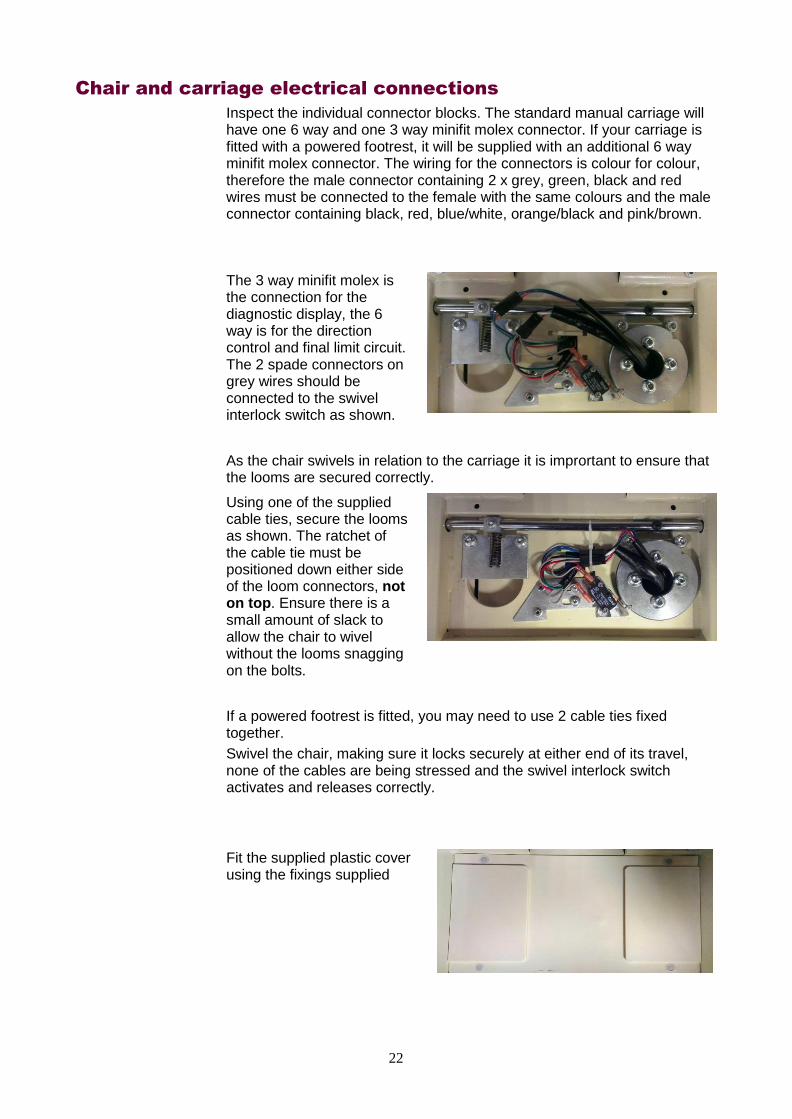
Inspect the individual connector blocks. The standard manual carriage will have one 6 way and one 3 way minifit molex connector. If your carriage is fitted with a powered footrest, it will be supplied with an additional 6 way minifit molex connector. The wiring for the connectors is colour for colour, therefore the male connector containing 2 x grey, green, black and red wires must be connected to the female with the same colours and the male connector containing black, red, blue/white, orange/black and pink/brown.
The 3 way minifit molex is the connection for the diagnostic display, the 6 way is for the direction control and final limit circuit. The 2 spade connectors on grey wires should be connected to the swivel interlock switch as shown.
As the chair swivels in relation to the carriage it is imprortant to ensure that the looms are secured correctly.
Using one of the supplied cable ties, secure the looms as shown. The ratchet of the cable tie must be positioned down either side of the loom connectors, not on top. Ensure there is a small amount of slack to allow the chair to wivel without the looms snagging on the bolts.
If a powered footrest is fitted, you may need to use 2 cable ties fixed together.
Swivel the chair, making sure it locks securely at either end of its travel, none of the cables are being stressed and the swivel interlock switch activates and releases correctly.
Fit the supplied plastic cover using the fixings supplied

23
Chair Ergonomic Alteration.
The chair can be individually tailored to better fit the customer or installation area. The arm rests can be widened or made shorter, and the seat pad can be moved forward.
The arm rests can be made shorter and/or further apart by removing the 4 x allen bolts, repositioning the arms and replacing the bolts.
Position 1. Fully extended, fully forward. This will give maximum seat width with maximum length of useable armrest.
Postion 2. Fully extended, fully back. This will give maximum width of seat with minimum useable armrest. (For use
when swivel radius width at top of stairs is reduced.)
Position 3.Mid extended, fully forward.
Position 4. Mid extended, fully back.
Postion 5. Minimum extended, fully forward. This is how the chairs are supplied as standard/
Position 6. Minimum Extended, fully back. (For use when swivel radius width at top
of stairs is reduced.)

24
When using positions 2, 4 & 6, the arm rest angle will need altering. Remove 4 x pozi screws in bottom of armrest cover. Remove armrest top.
Remove Bolt.
And Replace here.
The Seat pad can be moved forwards. Undo the zips on the seat pad. Remove the 4 allen bolts shown on the right, reposition seat pad. Replace bolts.
25
Test Running the Stairlift, Unladen and Unprogrammed.
Important: If there any issues with the stairlift, the system may display System Status Codes. Refer to the System Status Codes section for more details of what these codes mean.
To test run the stairlift (unladen):
Make sure the area covered by the movement of the stairlift is free of obstructions.
Fold down the footrest and swivel the seat into correct travel position. Leave the armrests in the upright position. Do not allow any weight to rest on the carriage as yet.
Run the unladen stairlift to the very bottom of the track. While the stairlift is travelling check:
1. Footrest to riser, especially on fanning staircases
2. Armrest and seat back, especially on staircases with low bulkheads.
3. Seat back to wall/newel, especially on internal staircases
4. Back of armrest mounting to wall, especially on external bends
At the bottom check that the stairlift is charging correctly and the footrest is at the correct height to allow the user to easily access the stairlift.
Run the stairlift to the top of the track while checking all above points.
At the top check that the stairlift is charging correctly and the footrest is at the correct height to allow the user to easily access the stairlift. Also check the swivel radius to ensure that the downside armrest does not come into contact with the opposite side of the staircase.
Programming the Carriage
The lift must now be programmed for the rail. All programmable features are accessed and set throught the menu system of the control system. The speed, lift type, hand,swivel type and language settings now need to be set. The menu also contains settings for intermediate charge point behaviour and audiable travel warnings.
The lift can travel at one of two speeds, Half speed and Full speed. Half speed must be used at either end of the stairlift travel to ensure that the stairlift comes to a safe and gentle stop. This will also ensure that the stairlift does not “over-run”. Half speed must also be used on a small radius “internal bends”. This is for the users comfort as travel around these bends at full speed can feel as though you are being pushed forward, out of the seat. It will also ensure that the carriage does not cause excessive wear on the rail racking.
The lift uses an encoder to create a map of the rail and the program defines what speed the lift will travel at different points on the rail. The lift uses the bottom skate, metal paddle activation to signify it’s datum “0” point, therefore the lift must always be programmed from bottom to top.
The half-speed and full-speed sections can only be programmed when the lift has been installed and the batteries at least partially charged. The charge circuit also needs to be connected
The lift will run at half-speed when it is in learning mode.
If you need to re-start the learning process, power the lift off, power it back on again and run the lift to the bottom stop.

26
To Program the lift:
If the PCB side plastic cover is not already removed, undo the two 7mm nuts and plastic washers located at the bottom of the cover. The cover can then be removed taking care not to damage the locating lugs at the top.
Bring the lift to the bottom stop/charge point, and ensure the lift is correctly on charge. The diagnostic display should read “Platinum”. .
There are 2 red momentary buttons located on the PCB. The button on the right, Menu Switch, cycles through the various memory options, the button on the left, adjust Switch, changes the chosen option.
The first operation is to set the hand of the lift. This is defined by the side of the staircase that the rail is fitted to when viewed from the bottom.
Press the menu button twice until either “Left Hand” or “Right Hand” is displayed. Press the adust button to change the selection.
If the powered swivel option is fitted, the next menu option sets the swivel type. Cycle through the menu until either “Manual” or “Powered Swivel” is displayed using the menu button, and adjust selection using adjust button.
The language of the diagnostic display is defaulted to English but can be set to Dutch, French, Italian, Spanish, Portuguese or German from within the menu. If an intermediate charge point is fitted, and is to be used as an entry/exit point for the user, cycle throught the menu and adjust “Landing Pass” to “Landing Stop”. If an unladen travel audiable warning is required, cycle throught the menu and adjust “Quiet Travel” to “Travel Alarm”. There is a setting in the menu to set the position of the diagnostic display. Arm, for a display in the armrest, Display for the display in the front panel of the carriage and Either for, you guessed it, either. The PCB can also be set to run the forthcoming Platinum Straight lift using the setting Curved or Straight. (Straight setting must not be used on a curved lift as it increases the speed and disables the speed programming procedure).

27
The diagnostic display will time out after approx. 8 seconds back to it’s normal state, displaying “Platinum”. Press and hold the menu button for 4 seconds until the display changes to “Program 0000”. You will notice a small S in the bottom right hand corner of the display. This indicates that the first section to be programmed is a slow, half speed section. The 0000 indicates that you are at the bottom of the track. Move the lift upwards approx. 250mm and stop. The number displayed will increase.
Press the adjust button once, and the S will be replace with an F. This indicates that the next section to be programmed is a fast, full speed section.
If there are any tight radius, internal bends, the lift needs to travel at half speed around these. Use the adjust button to switch between Full and Slow speed for every internal bend.
If the rail configuration includes a parking wrap at the bottom, it is usually better to keep the lift at half speed from the bottom of the track until after the internal bend.
If an intermediate parking point is going to be used for the customer to get on/off the lift on intervening floors, the lift should be slowed to half speed 250mm before the charge point and can be returned to full speed 250mm after.
Continue until the lift comes to the end of the rail, ensuring that you program the lift to slow at least 250mm before it comes to rest against the top stop.
The lift will recognise that it has reached the top and exit programming mode. The display will revert to “Platinum” and the carriage will travel according to the program
28
Installing the Remote Controls
There are 2 types of remote control:
1. Infra-Red. These controls have 3 buttons, Up, Down and a Red park button. The park button is only used in conjunction with the optional intermediate charge point. This is the Standard control supplied with most stairlifts.
2. Radio. These controls have 2 buttons, Up and down only. This is the control supplied if the radio option is ordered. If park function is required with RF controls, Landing Stop must be selected in the menu system.
To install the remote controls: Infra-Red
The infra-red receivers are mounted in the arm of the chair.
Fit the batteries into the remote controls, then use each of them to call and send the stairlift to and from the other end of the track and then back again.
Locate suitable locations for the control holsters to be mounted, confirm these postions are suitable for the customer, and screw into position.
The controls are sent pre-programmed to the PCB. However, if there are several stairlifts installed in close proximity or there are other infra-red/radio sources in the area creating interference, the Infra-Red signals for each of the stairlifts can be changed so that they do not interfere with each other.
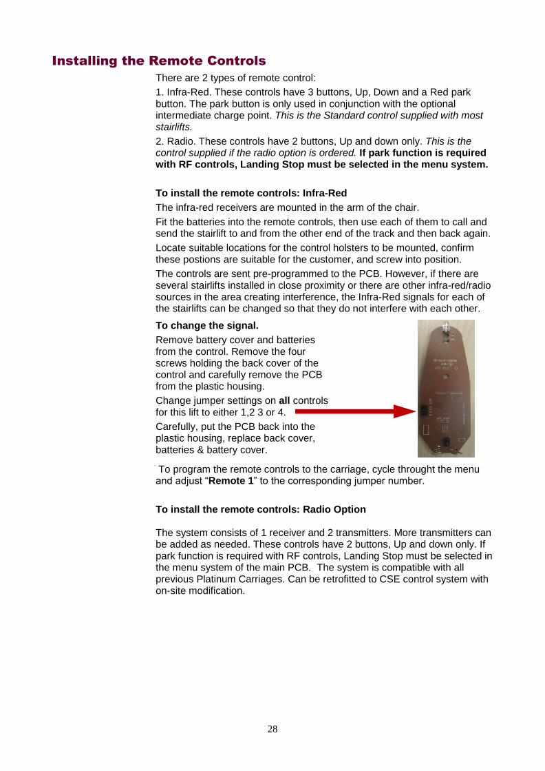
To change the signal.
Remove battery cover and batteries from the control. Remove the four screws holding the back cover of the control and carefully remove the PCB from the plastic housing.
Change jumper settings on all controls for this lift to either 1,2 3 or 4.
Carefully, put the PCB back into the plastic housing, replace back cover, batteries & battery cover.
To program the remote controls to the carriage, cycle throught the menu and adjust “Remote 1” to the corresponding jumper number.
To install the remote controls: Radio Option
The system consists of 1 receiver and 2 transmitters. More transmitters can be added as needed. These controls have 2 buttons, Up and down only. If park function is required with RF controls, Landing Stop must be selected in the menu system of the main PCB. The system is compatible with all previous Platinum Carriages. Can be retrofitted to CSE control system with on-site modification.

29
To install with Benchmark Control System 1. Turn off main battery isolator switch 2. Remove side cover over main PCB 3. Connect RF receiver as follows:- Red +24v Out Black 0v/Ground Brown Call Down White Common
Blue Call Up
The radio option requires a small PCB, set in a black plastic housing, to be mounted to the stairlift, on the inside of the large plastic side cover over the main PCB. This should then be connected to the main PCB, black to 0v, red to +24v and the three direction control wires, Blue to Call up, Brown to Call down and White to Feed should be connected to the corresponding spade connectors on the main PCB below the large green limit connectors, as detailed in the picture above and the connection diagram later in this manual.
Fit the batteries into the remote controls, then use each of them to call and send the stairlift to and from the other end of the track and then back again.
Locate suitable locations for the control holsters to be mounted, confirm these postions are suitable for the customer, and screw into position.
The controls are sent pre-programmed to the PCB. However, if there are several stairlifts installed in close proximity or there are radio sources in the area creating interference, the Infra-Red signals for each of the stairlifts can be changed so that they do not interfere with each other.
The controls are sent pre-programmed to the PCB. To program further transmitters to the receiver follow the steps below.
To change the signal.
Remove battery cover and batteries from the control. Remove the four screws holding the back cover of the control.
Remove the four small screws holding the cover for the receiver (black plastic enclosure) Carefully remove the cover feeding the wires through the holes as you go.
Change dip switch settings on receiver and all controls for this lift.
Carefully, replace all covers and batteries.

30
The RF control system can also be fitted to the old CSE control system with slight modification. 1.Turn off main battery isolator switch 2.Remove side cover over main PCB 3.Cut off the female spade connectors from the Blue, White & Brown wires, bare 3-5mm of center conductor. 4.Insert wires from RF Receiver into large green 8 way connector for main PCB with existing wires in place as follows:- Red +24v / VBatt Black 0v / Gnd Brown Call Down/With Green wire pin 1, conn 20 White Common/With Black wire pin 2, conn 20
Blue Call Up/with Red wire pin 3, conn 20

31
Test Running the Stairlift, fully laden and programmed
Important:
The lift must be tested up to it’s full laden capacity before handover to the customer.
Test running the stairlift fully laden ensures the lift is working correctly, and that it clears any obstacles.
It also begins the bedding in process. Please ensure that the racking is lubricated with a suitable silicone or synthetic PTFE based grease at this point. We recommend that you lubricate three teeth every 300mm on the rack.
Do not over lubricate the rack as this may cause problems with the over speed assembly due to lubricant/debris build up in the bottom skate of the carriage.
To test run the stairlift (fully laden):
Move the stairlift to the bottom of the track, fold down the armrests and footrest, Load the chair to capacity. Using one of the remote controls, send the stairlift to the top of the rail
If the powered swivel option is fitted, keep direction control activated to ensure chair automatically swivels to safe entry/exit position. Press remote control in opposite direction to ensure chair swivels back to correct travel position.
To test manual swivel, depress swivel levers, and ensure chair will swivel into correct entry/exit position. Press direction control in downwards direction to ensure swivel interlock switch is working, and stairlift will not decend in this position. Depress swivel levers and ensure chair swivels back to correct travel position.
Use remote control to send stairlift down the stairs, stop part way along the rail and then reverse direction to bring stairlift back to the top, ensuring the stairlift slows and stops correctly.
Use the remote control to travel down the stairs. Ensure the stairlift slows and stops correctly.
Ensure the stairlift starts, stops, proceeds along the straight sections and corners smoothly at the correct speed. If the entire journey takes place at half-speed the stairlift is still in learning mode.
Make sure the stairlift comes to a stop quickly, if you do any of the following actions:
Let go of the direction control
Encounter an obstruction with the footrest.
Encounter an obstruction with the safety pads on the carriage.
Move the seat swivel lever.
Run the stairlift from one end of the track to the other; then return it to its original position. For both trips make sure it runs freely and smoothly, and proceeds clear of stair treads and any other fixed obstructions.
At one end of the track, stop the chairlift at one end of the track, undo the seatbelt and make sure the plug part of the lock retracts into its housing.
Lift up the seat, footrest and arm rests and make sure they all stay upright.
Run the stairlift to the middle of the track, then stop it. Use the hand-winding procedure to make sure the chair can be hand-

32
wound both up and down the track (refer to the instructions printed adjacent to the hand-winding mechanism).
Final Checks
Once the lift has been installed, a series of tests must be performed ensure that the installation has been completed correctly and that the system works correctly and safely.
Contract/Installation Drawing
Check that the installed system has been installed in accordance with:
The instructions on the contract
The Installation Drawing
Electrical, Battery and Operational Tests
Detailed measurements and tests must be carried out before handover to the customer. An example of these tests are detailed on the “Platinum Stairlifts Certificate for Test & Examination After Installation” form on the next page. This is the document that our installers complete and it ensures that all electrical and safety systems are working correctly and that the stairlift operates in a safe manner.
It is recommended that your company use a certificate such as this when installing our prouct.
Clean Work Area
Before demonstrating to the user, please ensure that work area is left clean and tidy. As drilling has taken place in this area it is recommended that the area is checked for swarf and thoroughly vacuumed.
Please remove any packaging not required by the user from site and, if possible, recycle.

33
Certificate for Test & Examination After Installation
Platinum Stairlifts Unit 10, Crosshills Business Park Crosshills, Keighley, BD20 7BW Tel:- 01535 631177 Fax:- 01535 631188
………Kg

34
Instructing the User
Before using the stairlift for the first time the customer must be instructed in the safe use of all aspects of the stairlift. The User guide is a good starting point for this instruction.
Once the training is complete, the User Guide must be retained by the user of the stairlift.
You now need to instruct the user (and any carers, helpers or other family members), how to use the lift. The demonstration should include:
Introduction to the Stairlift.
Installer Demonstration of the Stairlift.
Resident Use of the Stairlift.
Introduction to the Stairlift
Show the user the installed stairlift and point out all of the key features, including:
Footrest, arm rests and fold-down seat.
Seat Belt (lap belt) and locking mechanism.
Safety Pads and need to keep free from obstructions.
Direction Controls – armrest and remote control.
Power-on switch and key-switches.
Emergency hand-wind mechanism.
Installer Demonstration of the Stairlift
The installer should then use the stairlift themselves to demonstrate the following:
How to fasten and unfasten the lap-belt, and stress how important it is to use this at ALL times.
How to use the Remote Control to move the stairlift up and down the stairs.
How to fold up and fold down the footrest, seat and arm rests, and why you need to do this.
How to use the swivel seat, how to sit on the seat safely at the top and the bottom of the stairs.
How to get up from the seat safely.
How to use the direction controls to go up and down; how to stop, start and change direction.
How to move items on the chair (items such as laundry, toiletries, etc must be boxed and held on the seat with the seatbelt).
How to lock the stairlift so it can not be used as a plaything – for example if children are visiting.
How to Open the Remote Control to replace the batteries (every six months).

35
Resident use of the stairlift
The installer should then guide the resident to use the stairlift so they are completely familiar with the stairlift and its safe operation, including:
Using the remote control to send or bring the stairlift.
Safely using the swivel seat to get on the stairlift at the bottom of the stairs, fastening the seat belt, going to the top, unfastening the seat belt, and safely using the swivel seat to get off the stairlift at the top of the stairs. And this equivalent procedure for going to the bottom of the stairs.
How to start, stop, reverse and chairlift using the direction controls.
How to move items on the chair (must be boxed and held on with the seatbelt).
How to lock the stairlift.
Make sure the resident and any-one else asks any questions they want to.
Ensure the customer understands what the Diagnostic display codes mean.
Ensure the customer understands what to do in the event of a breakdown.
Ensure the customer is aware of your companys service procedure.
Ensure the customer has the correct contact telephone numbers in the event of a breakdown or to request Service calls.
Paperwork
Signing the Test Certificate
If a test certificate has been used to provide a checklist of important tests and checks that need to be made by you, it should now be shown to the customer. This will demonstrate that all the tests have been done correctly, and that the installer has completed the installation to a satisfactory standard.
It also provides a proof that the customer is happy with the installation and the instruction given, and they have formally accepted it as an installed and working system in their premises.
When the installation and instruction is complete, both parties should sign and date the Certified section of the test certificate.
User Guide
Hand a copy of the Platinum Curve User Guide to the customer, requesting that they keep it to hand for easy reference by themselves, any family members, carers or other helpers.
An Installation & Service Record sheet is contained in the User Guide and should be signed and dated upon completion of installation.

36
Offset Footrest Option

37
Connection Diagram

38
Technical Information
Weight Limits
The stairlift has been designed to carry one person only, in a seated position. The standard stairlift has a maximum weight limit of 120kg (19 stone) and the heavy duty stairlift has a maximum weight limit of 160kg (25 stone).
Operating Periods/Excessive Use
The stairlift has been designed to run for four minutes with a break of at least six minutes afterwards. If you use the stairlift too often without taking a break, the motor will not cool down between journeys and may become damaged.
Replacement Batteries
We recommend that the batteries in each remote control are renewed at least every six months. This is the resposibilty of the user,
Maintenance
To maintain safe and reliable operation, the standard stairlift needs a annual safety inspection and service. The heavy duty stairlift requires a service every 6 months.
CAUTION: Modifications which have not been expressly approved by the manufacturer may void the warranty and may cause damage. Your stairlift should be inspected and maintained by a Platinum approved service engineer.
Hand Winding the Stairlift
If necessary, for example to release the safety gear after the OSG has activated or to return the carriage from an over-run position, the stairlift can be manually hand-wound using the supplied winding handle.
If the OSG has been activated, the carriage should only be hand-wound in the upwards direction.
The batteries must be connected to release the brake before winding.
To hand-wind the stairlift:
Switch the On/Off switch (11) to the ‘0’ (Off) position.
Fully insert the winding handle into the Emergency Hand Wind Mechanism Socket (5) and push in until it clicks, releasing the brake.
Keeping the handle fully inserted, carefully rotate it as needed. If you rotate the handle clockwise, this will move the chair to the right. If you rotate the handle anti-clockwise, this will move the chair to the left.
Never use the stairlift when the winding handle is in the socket.
Upholstery
Carelessness with matches, cigarettes and so on can cause a fire. The upholstery material used on your stairlift has been tested for compliance with BS5852.

39
Diagnostic Codes
These codes are displayed on the Diagnostic display panel on the carriage:
Code Meaning
No Display
No power
1. Check the battery isolator switch is in the “I” position
2. Check batterys are correctly connected and in good order
Platinum OK
The stairlift is on charge and everything is OK, lift should operate normally.
Safety Circuit Final Limit Fault/Safety Circuit short to 0v
1. Check keyswitch is on connected and working
2. Check seat swivel switch is connected and working
3. Check if the stairlift has over-run and switch is connected and working
4. Check if OSG and Safety gear has actioned and switch is connected and working
Low Battery Batteries Need Charging
Stairlift batteries are down to 21V.
1. Check transformer is plugged in to mains socket and turned on.
2. Check charging point voltage is present unloaded and loaded.
3. Check charge voltage is present on white charge connector on main PCB.
Off Charge Lift is off Charge
Stairlift batteries are not charging (the stairlift may still work). To charge them:
1. Move the stairlift to a charging point
2. Check transformer is plugged in to mains socket and turned on.
3. Check charging point voltage is present unloaded and loaded.
4. Check charge voltage is present on white charge connector on main PCB.
End Stop End Stop Activated (bottom skate metal cover left and right)
Ensure that both track and staircase are clear of obstructions.
Safety Edge Lift stopped by safety edge in direction of travel (footplate, top skate, side cover)
Ensure that both track and staircase are clear of obstructions.
Move Right Lift travel direction
Right.
Move Left Lift travel direction
Left.

40
Code Meaning
Seat Swivel Seat in Swivelled position (Powered Swivel Only)
Lift cannot move until powered swivel seat is returned to travel position.
1. Check Powered swivel option is selected in menu.
2. Check lift is set as correct hand in menu.
3. Check lift is at top of track and bottom skate end stop is activated.
4. Check transformer is plugged in to mains socket and turned on.
5. Check charging point voltage is present unloaded and loaded.
6. Check charge voltage is present on white charge connector on main PCB.
Lost Position Lift has lost datum position
Move lift to bottom of track to reset datum position.
1. Check lift is set as correct hand in menu
2. Check encoder is connected correctly.
Thermal Cut Out Motor and motor drive are running too hot, overloaded lift or excessive use.
Switch lift off and allow motor to cool.
Call Conflict More than one conflicting call received.
Direction toggle or wall control direction button stuck on.
Release Joystick Conflicting call received.
User needs to release joystick and re-input call.
Brake Fault Motor brake inoperable.
Reset lift. Check brake connection on main PCB and reset lift.
Relay Fault Power relay did not close
Check battery charge level. Reset lift.Tap Relay. If problem persists, renew PCB.
There are also 3 thermal fuses on the the PCB. If any of these fuses are activated, a red LED located nearby will light.This generally indicates a wiring fault on one of the circuits connected to the PCB in the surrouding area to that LED.

41
Engineers Menu
Further diagnostics and settings are available by cycling through the menu system.
Code Meaning
Position 12345 Lifts current position on rail. Bottom end stop is 00000. Press and hold menu button to reprogram.
Remote 1/2/3/4 Shows current Remote channel selection. Press adjust button to change.
Right/Left Hand Shows current installation hand selected. Press adjust button to change.
Quiet Travel / Travel Alarm
Shows current travel alarm selection. Press adjust button to change.
Landing Stop / Pass
Shows current landing selection. Press adjust button to change.
Powered / Manual Swivel
Shows current swivel selection. Press adjust button to change.
Edge 123 Number of sensitive edge trips since last engineer reset. Press adjust button to reset to 0.
Low Batt 123 Number of low battery events since last engineer reset. Press adjust button to reset to 0.
Trips 12345 Number of trips (up or down) done by control system. Not resettable.
Safety 123 Number of safety circuit trips since last engineer reset. Press adjust button to reset to 0.
Brake 123 Number of brake faults since last engineer reset. Press adjust button to reset to 0.
Relay 123 Number of relay faults since last engineer reset. Press adjust button to reset to 0.
LostP Number of times position has been lost since last engineer reset. Press adjust button to reset to 0.
Battery Bar (bar display 1-8)
A bar display of battery voltage. Approx. 21V (all off) to 27V (all on).
Low Battery Battery below 21V
Mains Power, Battery Power and Power Cuts
The DC charger supplies power to a set of large internal batteries. These batteries then power the motor which lifts the chair up and down the stairs.
If the mains power fails, you can continue to use the stairlift for a short while as the batteries store enough power to allow you up and down the stairs a few times.

42
Servicing
The Standard 120 Kg (19 stone) stairlift requires a service every 12 months.
The Heavy Duty 160Kg (25 stone) stairlift reqires a service evey 6 months.
Items listed below should be checked and renewed if necessary.
If pinion and/or main load roller need replacing, you will require an 3 legged bearing puller to remove pinion and cam.
When reassembling, ensure pinion and cam keys are inserted and aligned correctly. The pinion/cam must be wound or pressed back into place.
Hammering will break motor/gearbox oil seals and void warrenty.
When replacing the circular, free spinning pinion guard, the bolt must be re-fit using using loctite type 272.
Services should only be carried out by a competent stairlift engineer.
Service Carriage
Remove carriage from rail. Turn off.
1. Top Skate. Remove all skate covers.
Check rollers for wear/damage. To renew rollers, remove 17mm bolts discard old rollers, lubricate bolt shafts lightly, and fit new rollers. The bolts must be replaced using loctite type 272 (or local equivelant) and tightened to 40NM.
Check all rollers rotate freely.
Check all yokes rotate freely.
Check skate swing arm rotates freely and there is no excessive front to back play.
Check all wires and connectors for damage & and operation of all switches.
Remove any debris and clean all surfaces.
Replace all covers ensuring spacers, springs and nuts are all present and correct. Check operation of safety edges.
2. Bottom Skate. Remove all skate covers.
Check rollers for wear/damage. If replacing, lubricate roller shafts lightly.
Check pinion for wear/damage.
Check pinion guard rotates freely.
Check all rollers rotate freely. If necessary lubricate roller shafts lightly.
Check bottom skate revolves freely to limit of wiring loom on drive shaft. (If action feels notchy this could be an indicator of bearing damage.
Check bottom skate moves freely along drive shaft. Lubricate if necessary.
Check all wires and connectors for damage & and operation of all switches.
Check operation of OSG and safety gear. Pay close attention to condition of large main load roller.
Check operation of charge pin and final limit switch.
Remove any debris including excessive, built up grease and clean all surfaces.

43
Replace plastic covers ensuring they fit together correctly. Replace metal covers ensuring the springs are in place and safety edges operate correctly.
Re-load carriage on to rail. Re-fit end stop.
3. Carriage Body. Remove side covers.
Check all wiring and connectors to PCB.
Check all wiring and connectors to batterys.
Check battery condition. Replace if necessary.
Check battery retaining strap.
Check break release and hand-wind mechanism operates correctly.
Check wiring, connectors and switches on side cover safety edges.
Remove any debris and clean all surfaces.
Ensure footrest operates correctly.
Ensure footplate safety edges operate correctly.
Ensure footrest carpet is fixed correctly.
If powered footrest option is fitted, check all wiring, connectors and mechanical linkages. Ensure the area is free of debris. If necessary lubricate. Check operation.
Replace side covers ensuring they fit correctly and safety edges operate correctly.
Ensure Diagnostic Display shows correct codes.
4. Chair. Remove center seat pad.
Check all wiring and connectors.
Ensure the 4 x M8 x 10 Hex bolts are tightened to a torque of 20 Nm..
Ensure manual swivel mechanism is free of debris and operates correctly.
Ensure swivel interlock switch operates correctly.
If powered swivel option is fitted, remove plastic covers, check all wiring and connectors, ensure the area is free of debris. Check operation and replace plastic covers.
Check arm rests operate correctly.
Check seat belt operates correctly.
Check all controls operate correctly.
Repace seat pad.

44
Service Rail
Clean excessive grease off racking and inspect for damage/wear. If necessary re-apply lubrication. We recommend that you lubricate three teeth every 300mm on the rack.
Inspect rack jointing bolts and replace/re-fit if necessary.
Clean rail tubes and inspect for damage/wear.
Check combined end stops/charging ramps are fixed firmly and in the correct position.
Inspect all sprung roll pins on rail joints and legs and replace/re-fit if necessary.
Inspect all leg screws and replace/re-fit if necessary.
If wall brackets are fitted, inspect screws and bolts and replace/re-fit if necessary.
Check charge circuit is operating correctly.
Check carriage stops in the correct position at the top and bottom.

45
Notes:

46
Notes:

47
Notes:

48
Unit 10, The Crossings, Crosshills Business Park, Keighley BD20 7BW Telephone 01535 - 631 177 Fax 01535 - 631 188
Email [email protected]